


Find Quality Products Online at: sales@GlobalTestSupply.com
www.GlobalTestSupply.com

USER MANUAL OPTIMA 7
Legal notices / Intellectual property rights comments
Original user manual
© 2021 by MRU
No part of this manual my be published in any form (print, fotocopy,
electronic media or any other publication form) without a written
approval by the publisher.
All user trade marks and name mark descriptions, even those which are
not marked as such, are properties of the respective owners.
Edition: 2021-04-19,V3.10.EN
2 / 76
Find Quality Products Online at: sales@GlobalTestSupply.com
www.GlobalTestSupply.com

Find Quality Products Online at: sales@GlobalTestSupply.com
www.GlobalTestSupply.com

Find Quality Products Online at: sales@GlobalTestSupply.com
www.GlobalTestSupply.com

Find Quality Products Online at: sales@GlobalTestSupply.com
www.GlobalTestSupply.com

Find Quality Products Online at: sales@GlobalTestSupply.com
www.GlobalTestSupply.com

Find Quality Products Online at: sales@GlobalTestSupply.com
www.GlobalTestSupply.com

USER MANUAL OPTIMA 7
NOTE
The battery life is at least 500 charge-discharge cycles.
With increasing number of charging cycles the battery capacity (indicated in operating hours) is reduced.
1.5. User guideline for rechargeable batteries
The rechargeable batterie is installed inside the analyser and is not accessible to the end customer. However, the following instructions must generally be observed when handling lithium-ion rechargeable batteries.
This rechargeable battery can only be used in this analyser.
Do not throw the rechargeable battery into a fire, charge it at high
temperatures and store it in a hot environment.
Do not deform, short-circuit or modify the rechargeable battery.
The rechargeable battery must not be used in or under water.
Do not expose the rechargeable battery to strong mechanical forces
and do not throw it.
Do not cut or squeeze the connecting cables of the rechargeable
battery.
Do not connect the (+) contact to the (-) contact or metal.
Non-observance of the above guidelines can cause heat, fire and explosions
Find Quality Products Online at: sales@GlobalTestSupply.com
www.GlobalTestSupply.com
8 / 76

Find Quality Products Online at: sales@GlobalTestSupply.com
www.GlobalTestSupply.com

Find Quality Products Online at: sales@GlobalTestSupply.com
www.GlobalTestSupply.com

Find Quality Products Online at: sales@GlobalTestSupply.com
www.GlobalTestSupply.com

Find Quality Products Online at: sales@GlobalTestSupply.com
www.GlobalTestSupply.com

USER MANUAL OPTIMA 7
3.2. The Analyser
The compact analyser is made from a fibre re-enforced plastic material
with all measurement related connections at the bottom of the analyser.
Position Description
1 Display
2 Key pad
3 Temperature connector T2
4 Temperature connector T1
5 Pressure connector P1
6 Pressure connector P2
7 Gas outlet
8 IR-Interface
9 USB-port and charging port
10 SD-card reader
11 Fixing magnets
12 Analyzer feet
13 Handle strip
14 Gas outlet
15 Pressure connector P3
16 Connector AUX
ATTENTION
Gas outlet:
During measurement the gas outlet must not be covered
Find Quality Products Online at: sales@GlobalTestSupply.com
13 / 76
www.GlobalTestSupply.com

Find Quality Products Online at: sales@GlobalTestSupply.com
www.GlobalTestSupply.com

USER MANUAL OPTIMA 7
(fixed)
probe pipe
and 2,7 m sam-
3.4. Extraction probes
The analyser is available with either a probe with fixed probe tube or with exchangeable probe tubes. A complete list of available probe options can be
found in our effective price list.
Here 2 variants are shown as examples:
Probe ST
With 180 mm probe pipe
Probe SF
With 300 mm exchangeable
1 Probe tube
2 Probe cone (high grade steel)
3 Triple hose (NBR or Viton)
4 Connector for sample gas measurement
5 Connector for draft measurement
6 Connector for temperature measurement
Find Quality Products Online at: sales@GlobalTestSupply.com
15 / 76
www.GlobalTestSupply.com

Find Quality Products Online at: sales@GlobalTestSupply.com
www.GlobalTestSupply.com

Find Quality Products Online at: sales@GlobalTestSupply.com
www.GlobalTestSupply.com

Find Quality Products Online at: sales@GlobalTestSupply.com
www.GlobalTestSupply.com

USER MANUAL OPTIMA 7
5 First usage
After the analyser has been inspected and is ready for start-up it can be
switched on and personalized settings can be entered. These settings can
be changed at any time.
5.1. Preparatory steps
Unpack the analyser.
Read the User Manual completely.
The analyser leaves the factory assembled and ready for use.
Nevertheless, check the device for completeness and integrity.
Charge the battery of the analyser for about 8 hours.
Check date and time. Modify if needed.
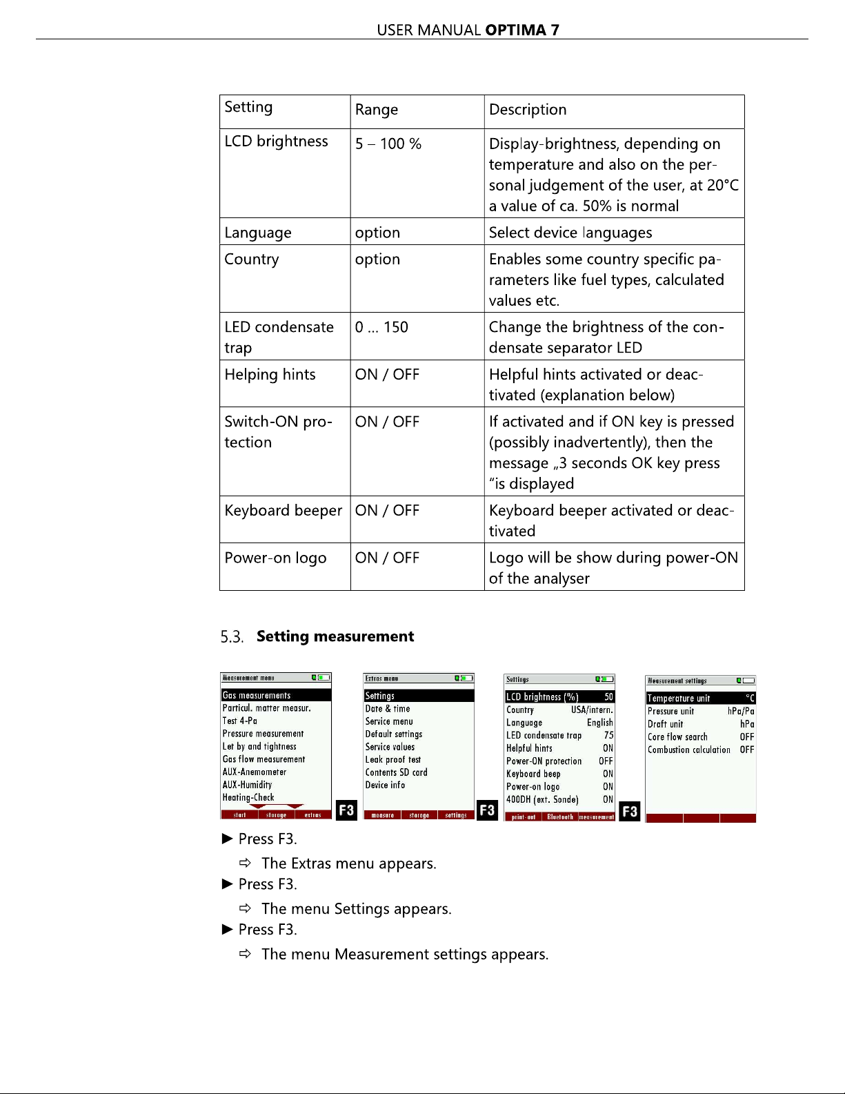
5.2. Analyzer settings
nstrument specific pa-
rameters.
-
. By selecting a line, the parameter value can be
changed by the arrow keys.
Find Quality Products Online at: sales@GlobalTestSupply.com
19 / 76
www.GlobalTestSupply.com
Find Quality Products Online at: sales@GlobalTestSupply.com
www.GlobalTestSupply.com

USER MANUAL OPTIMA 7
In the "Measurement settings" menu you can make for example the following adjustments:
Temperature Unit °C, °F
Pressure Unit Pa, hPa/Pa, hPa,
kPa/Pa, kPa,
mbar, mmH2O,
cmH2O, inH2O,
mmHg, inHg, PSI,
Draft Unit
Core flow search ON / OFF Core flow search before start of each
Combustion calculation
Pa, hPa/Pa, hPa,
kPa/Pa, kPa,
mbar, mmH2O,
cmH2O, inH2O,
mmHg, inHg, PSI,
ON / OFF
Change the unit for temperature in all
screens
Change the unit for pressure in all
screens. The meaning of hPa/Pa and
kPa/Pa is that the instrument performs
a dynamic change of unit depending
on the absolute value of pressure.
Change the unit for pressure in all
screens. The meaning of hPa/Pa and
kPa/Pa is that the instrument performs
a dynamic change of unit depending
on the absolute value of pressure.
flue gas measurement: activated or deactivated
If the combustion calculation is
switched off following items will be
changed:
- no fuel types, respectively always
"Sample Gas"
- no measuring values losses, ETA,
ETAcond, Dev. point
- no measuring value CO2, except it
will be measured
- no measuring values CO/NO/,,,. in
[mg/kWh]/[mg/MJ]
- no fuel type will be shown on the
menu bar and print-out
Find Quality Products Online at: sales@GlobalTestSupply.com
21 / 76
www.GlobalTestSupply.com

Find Quality Products Online at: sales@GlobalTestSupply.com
www.GlobalTestSupply.com

Find Quality Products Online at: sales@GlobalTestSupply.com
www.GlobalTestSupply.com

Find Quality Products Online at: sales@GlobalTestSupply.com
www.GlobalTestSupply.com

Find Quality Products Online at: sales@GlobalTestSupply.com
www.GlobalTestSupply.com

USER MANUAL OPTIMA 7
Adding fuels to fuel type selection
Select Gas measurements.
Press OK.
The menu Selection meas. program appears.
Press OK
The menu Fuel type selection appears.
Press F2.
The menu Fuel type list appears.
Select the fuel which should be added to the menu Fuel type selection.
Press F1.
The selected fuel is marked with a check mark
Select other fuels if necessary.
Press OK.
The selected fuels are displayed in the menu Fuel type selection.
Setting O2reference
Go to the menu Fuel type selection
See also Chapter Adding fuels to fuel type selection, Page 26
Select the desired fuel.
Press F3.
The menu fuel type appears.
Set the desired O2 reference.
Press OK.
The set O2 reference is saved.
Find Quality Products Online at: sales@GlobalTestSupply.com
www.GlobalTestSupply.com
26 / 76

Find Quality Products Online at: sales@GlobalTestSupply.com
www.GlobalTestSupply.com

Find Quality Products Online at: sales@GlobalTestSupply.com
www.GlobalTestSupply.com

Find Quality Products Online at: sales@GlobalTestSupply.com
www.GlobalTestSupply.com

Find Quality Products Online at: sales@GlobalTestSupply.com
www.GlobalTestSupply.com

Find Quality Products Online at: sales@GlobalTestSupply.com
www.GlobalTestSupply.com

Find Quality Products Online at: sales@GlobalTestSupply.com
www.GlobalTestSupply.com

Find Quality Products Online at: sales@GlobalTestSupply.com
www.GlobalTestSupply.com
Find Quality Products Online at: sales@GlobalTestSupply.com
www.GlobalTestSupply.com

USER MANUAL OPTIMA 7
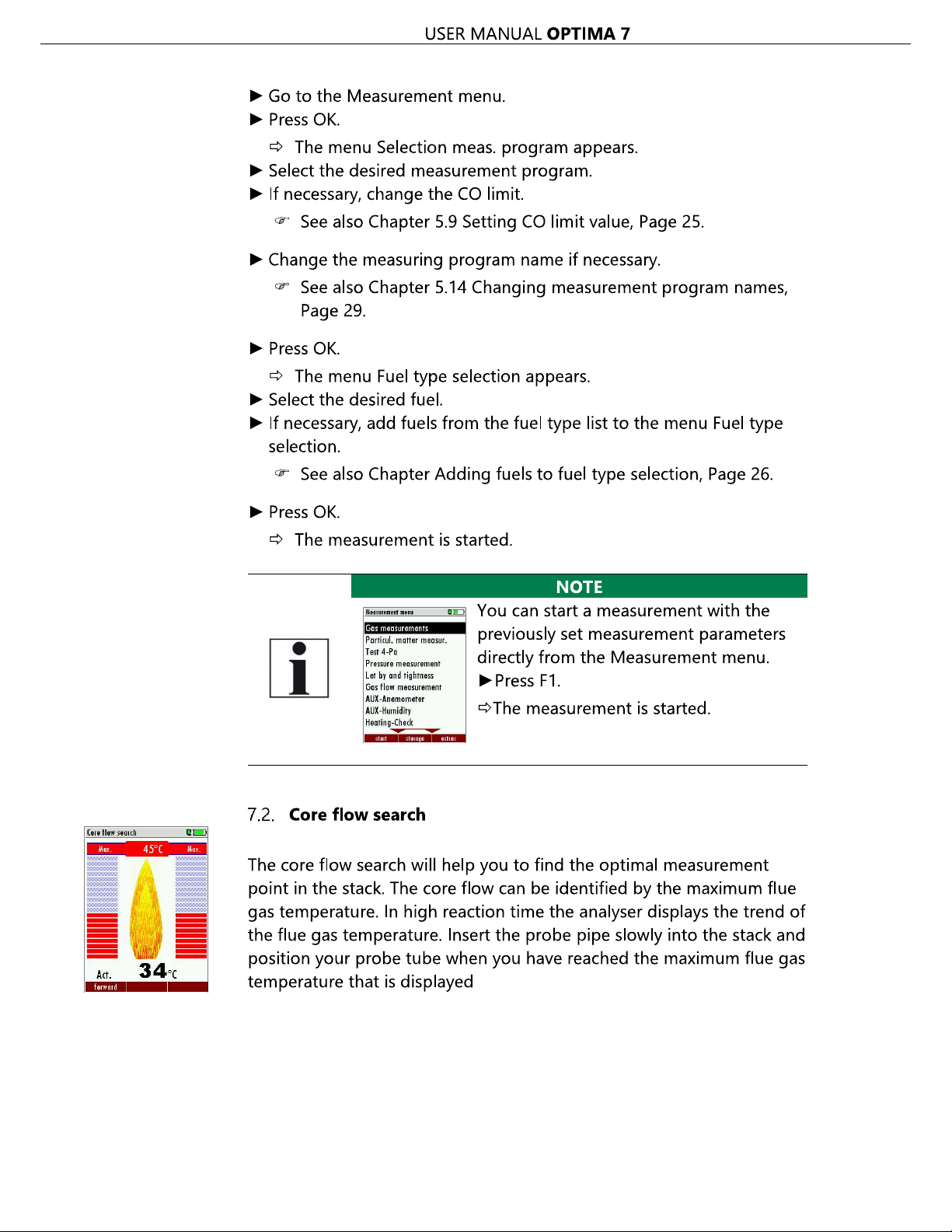
Before using the core flow search it must be switched-on:
Positioning the probe in the core flow:
Insert the probe pipe slowly into the stack and position your probe pipe
when you have reached the maximum flue gas temperature that is displayed (see temperature maximum value on the display in this case
45°C).
Maximum temperature has been reached when the arrows (left picture)
disappear, max. (Right picture) appears in place of the arrow, and the
beeper signal stops. Moving away from the max. Temperature will result
in the bars moving away from the max. Temperature (1 bar is equivalent
to 1°C). Once the right core flow has been achieved, the probe is fixed
with the probe cone screw.
7.3. Measured value display
After the core flow search you will see the measurement values on the
display.
Measurement values can be organized on three pages, each page displaying 6 measurement values.
The order of the display is operator settable.
There are direct measured values available such as Oxygen and Temperature as well as calculated values such as dew point, efficiency and CO2.
You will also find the same measurement value in different calculated
values such as CO in ppm or CO in mg/kWh.
Values that cannot be displayed are indicated with dashes. Possible reasons for value not being displayed are:
Electro chemical sensor was detected as defective during zeroing.
External temperature sensors are not connected.
The measurement value T- G
Find Quality Products Online at: sales@GlobalTestSupply.com
35 / 76
www.GlobalTestSupply.com

USER MANUAL OPTIMA 7
There are three measurement windows available, with the arrow keys
left and right moving between them.
Zoom function, each with two values, is activated by moving the arrow
keys up and down. Moving arrow keys left and right pages between the
two zoom windows.
7.4. Non-continuous draft measurement
The analyser provides for a non-continuous draft measurement. The
draft measurement is disabled when a maximum time after zeroing has
elapsed or a significant change in temperature has been detected by
the instrument. The maximum time is configured to 10 minutes.
If t --.-
To indicate that the draft measurement is not continuously available it is
displayed in colour red.
.
The frozen data is displayed in green.
The unfreeze the measurement one has to exit the menu and enter
again
All other measurements are processed continuously independent of the
draft measurement status.
Find Quality Products Online at: sales@GlobalTestSupply.com
www.GlobalTestSupply.com
36 / 76

Find Quality Products Online at: sales@GlobalTestSupply.com
www.GlobalTestSupply.com

Find Quality Products Online at: sales@GlobalTestSupply.com
www.GlobalTestSupply.com

USER MANUAL OPTIMA 7
Select Start zeroing.
Press OK.
A message appears.
The zeroing is performed.
After zeroing, you can start the CO Ambient test.
Select CO ambient
The menu CO (zero) appears. The current CO value (zeroing) as a
check is indicated. (This value must be approx. 0 ppm!)
Go to the measuring point.
Press F3.
The menu CO (peak) appears.
The CO Ambient test is performed.
The current CO (ambient) and CO (peak) values will be indicated.
Press F3.
The measurement is finished.
The CO (zero) value, CO (ambient) value and the CO (peak) value
are displayed.
Press the printer key to print out the measurement results.
Press the ESC key to return to the Measurement menu.
Find Quality Products Online at: sales@GlobalTestSupply.com
39 / 76
www.GlobalTestSupply.com

Find Quality Products Online at: sales@GlobalTestSupply.com
www.GlobalTestSupply.com

Find Quality Products Online at: sales@GlobalTestSupply.com
www.GlobalTestSupply.com

Find Quality Products Online at: sales@GlobalTestSupply.com
www.GlobalTestSupply.com

Find Quality Products Online at: sales@GlobalTestSupply.com
www.GlobalTestSupply.com

Find Quality Products Online at: sales@GlobalTestSupply.com
www.GlobalTestSupply.com

USER MANUAL OPTIMA 7
7.16.Differential temperature measurement (optional)
In the differential temperature measurement menu two temperatures
can be measured simultaneously by using the T1 and T2 connectors.
Both measured temperatures and the difference between the temperatures will be displayed.
Go to the Measurement menu.
Select Diff. Temp. Measurement.
Press OK.
The menu Diff. Temp. Measurement appears.
The temperatures T1, T2 and the difference are displayed.
NOTE
The accuracy of the difference temperature measurement is guaranteed only on use of the MRU temperature
sensors.
Find Quality Products Online at: sales@GlobalTestSupply.com
45 / 76
www.GlobalTestSupply.com

Find Quality Products Online at: sales@GlobalTestSupply.com
www.GlobalTestSupply.com

Find Quality Products Online at: sales@GlobalTestSupply.com
www.GlobalTestSupply.com

USER MANUAL OPTIMA 7
View sites
Go to the Storage menu.
Select Sites administration.
Press OK.
The menu Sites administration appears.
Each stored site is displayed on a page with the coloured site
number and eight additional free text lines.
If necessary, scroll through the sites until you have found the desired
site.
NOTE
You also have the possibility to search for sites by setting a search mask.
See also chapter Searching site, Page 48.
Searching site
You have the possibility to enter certain parameters in order to search
for particular sites. In the following example we will search for the site
that is assigned to John Example.
Go to the menu Sites administration.
Press the Menu Key.
A selection list appears.
Select Search a site.
Press OK.
The menu Search a site appears.
You can choose to filter by Site number, by content in Line 2 or
for the rest of the other text lines.
Find Quality Products Online at: sales@GlobalTestSupply.com
www.GlobalTestSupply.com
48 / 76

USER MANUAL OPTIMA 7
Select a line in which you want to search for content.
In this example, the search is performed in line 2.
Press F3.
A window appears.
Enter the desired search term.
In this example the search term is John Example.
Press OK.
The menu Search a site appears.
The search term appears in the selected line.
Press F2.
The site that is assigned to John Example is displayed. If several sites
were found, the total number is displayed in the header and you can
scroll through these found sites.
Changing sites
Go to the Storage menu.
Select Sites administration.
Press F2.
The menu Sites administration appears.
Select the site that you want to change.
Press F2.
A bar appears.
Select the free text lines that you want to change.
Press F1.
A window appears.
Enter the desired changes.
If necessary, select further free text lines and change the corresponding free text lines.
Press F3.
The changes are stored.
Find Quality Products Online at: sales@GlobalTestSupply.com
49 / 76
www.GlobalTestSupply.com

USER MANUAL OPTIMA 7
Deleting sites
You can delete sites individually or delete all sites simultaneously.
Deleting sites individually
Go to the Storage menu.
Select Sites administration.
Press F2.
The menu Sites administration appears.
Select the site you want to delete.
Press F3.
A message appears.
Select continue to delete the site
Select abort to retain the site.
Press OK.
Depending on the selection, the site is deleted or retained
Deleting all sites.
Go to the Storage menu.
Select Delete all sites.
Press OK.
A message appears.
Select continue to delete all sites.
Select abort to retain all sites.
Press OK.
Depending on the selection, the site is deleted or retained
Find Quality Products Online at: sales@GlobalTestSupply.com
www.GlobalTestSupply.com
50 / 76

Find Quality Products Online at: sales@GlobalTestSupply.com
www.GlobalTestSupply.com

USER MANUAL OPTIMA 7
ill get a
With this function you can Import Sites which have been created on a
computer or another Analyzer.
German for
sites). The file has no column heading that means that the first line already has user data. Each line has a minimum of 9 columns (with 8
semi-colons) and the first field in the line will be the site number. All
data will be imported as long a site number is available. Per field a maximum of 24 characters will be imported, too long words will be cut off.
Example file with 8 valid sites (4 with 9 lines and 4 with less lines):
A1-Z1;A1-Z2;A1-Z3;A1-Z4;A1-Z5;A1-Z6;A1-Z7;A1-Z8;A1-Z9
A2-Z1;A2-Z2;A2-Z3;A2-Z4;A2-Z5;A2-Z6;A2-Z7;A2-Z8;A2-Z9
A3-Z1;A3-Z2;A3-Z3;A3-Z4;A3-Z5;A3-Z6;A3-Z7;A3-Z8;A3-Z9
A4-Z1;A4-Z2;A4-Z3;A4-Z4;A4-Z5;A4-Z6;A4-Z7;A4-Z8;A4-Z9
A5-Z1;A5-Z2;A5-Z3;A5-Z4;;;;;
A6-Z1;A6-Z2;;A6-Z4;;;;;
A7-Z1;;;A7-Z4;;;;;
A8-Z1;;;;;;;;
Example file with 2 invalid sites (1 with not enough fields and 1 with
missing site number):
A1-Z1;A1-Z2
;A1-Z2;A1-Z3;A1-Z4;A1-Z5;A1-Z6;A1-Z7;A1-Z8;A1-Z9
NOTE
While importing data from the SD Card to the analyser
there is no check for double site numbers (Line 1), neither inside of the file that is imported nor between the
file and the sites already inside the analyser. The analyser
can easily handle double site numbers but you could
face problems with double site numbers when exporting
them again to a computer program (see also Export of
Measurements).
However, the analyser marks the files that have been imported successfully. If you try to import a file with the
same analyser that is already in the analyser you w
red information screen.
Find Quality Products Online at: sales@GlobalTestSupply.com
www.GlobalTestSupply.com
52 / 76
USER MANUAL OPTIMA 7
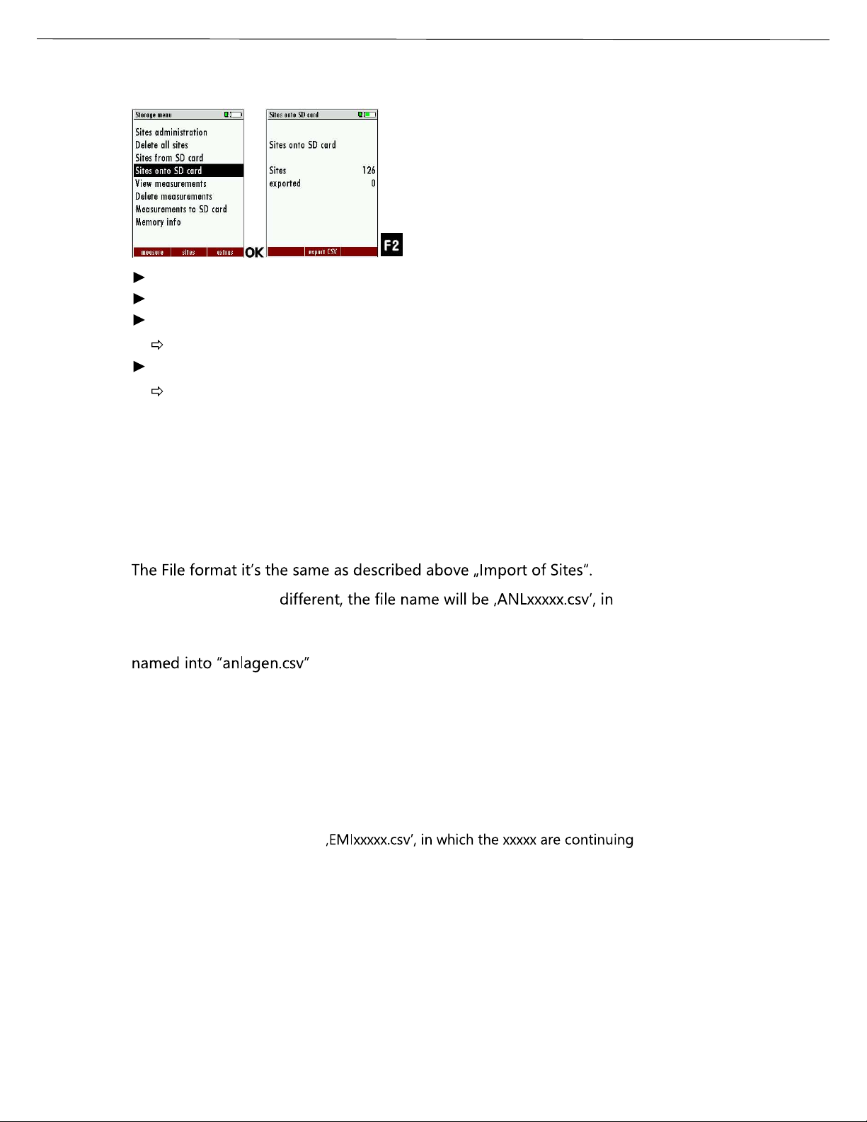
Exporting sites
Go to the Storage menu.
Select Sites onto SD card.
Press OK
The menu Sites onto SD card appears.
Press F2.
The sites are exported.
This function can be used for an analyser back up or if you wish to supply the analyser information to a computer program or another analyser. This is very handy if you have made some modifications inside the
analyser (site) for example if you have modified the phone number of a
customer and this modification needs to be updated in the computer
software, or if a second analyser needs to have the same site information.
Only the file name is
which the xxxxx are continuing 5-digit numbers with leading zeros. If
the file must be imported into another analyser, the file must first be re-
.
Exporting combustion measurements
This function is used to export the measurements from the analyser to a computer program.
This function is not suitable for back up or for the transfer to another analyser
because the exported file cannot be imported again!
The created file has the name
5-digit numbers with leading zeros.
The created file has a column header with the following information: Site number, Date/Time, Measuring program name, Fuel type, CO2max, O2reference,
and all measured values that the analyser can measure as well as the soot
numbers, Derivate and T-Boiler.
Find Quality Products Online at: sales@GlobalTestSupply.com
53 / 76
www.GlobalTestSupply.com

Find Quality Products Online at: sales@GlobalTestSupply.com
www.GlobalTestSupply.com

USER MANUAL OPTIMA 7
You have the possibility to display only those data that are assigned to a
single site:
played.
or while you select with the menu key the function "search a site"
and execute, as described in the chapter site administration.
Deleting measurements
You are able to
delete single measurements, while they are displayed press the key
F3 = "delete" .
or delete all measurements of a measuring type
Go to the Storage menu.
Select Delete measurements.
The menu Delete measurements appears.
Select which measurement type you want to delete.
Press F2.
A message appears.
Select continue to delete all measurements.
Select abort to retain all measurements.
Press OK.
Depending on the selection, the measurement data are deleted or
retained.
Find Quality Products Online at: sales@GlobalTestSupply.com
55 / 76
www.GlobalTestSupply.com

USER MANUAL OPTIMA 7
Transferring measurements to SD-Card (Option)
The analyser offers the possibility to export all stored measurements to
a SD card.
Go to the Storage menu
Select Measurements to SD card.
Press OK.
Select the desired measurement type.
Press F2.
The selected measurement type is transferred to the SD card
SD card is reported by the instrument. Make sure that the SD card is not
write protected.
The data are stored as a csv-file (e.g., EMI01032.csv) on the SD card. The
filename exists of a sequential number which fixes the device.
This file is editable on your Notebook/PC with a program like e.g. Microsoft® EXCEL or OpenOffice® Calc.
With possible problems with the using of your computer programs
please read your software documentations or ask your software dealer.
Find Quality Products Online at: sales@GlobalTestSupply.com
www.GlobalTestSupply.com
56 / 76

USER MANUAL OPTIMA 7
9 Extras / Adjustment
The analyser is delivered in a standard software configuration which
should cover most needs. However, there are many ways to tailor the
settings to your individual needs if required. The possibilities are highly
flexible and individual adaptable.
Use the variable possibilities to adapt your analyser to your own needs
and customize the measurement menu, the measurement window, the
printer output and many other features. Usually this is something you
will do once you receive the analyser, once you have adapted your analyser
you can whenever you need and want to do so.
After you have made any changes in the configuration, you should
switch off the analyser to save all the changes that have been made.
Next time that you start up the analyser, all changes will have been
made
9.1. Service calibration menu
The Maintenance adjustment menu is secured with a Pin Code to protect it against unauthorized users.
again.
Please contact MRU GmbH if you need the Pin Code for your analyser.
Press the Enter key if you should have landed in this menu by accident
Go to the Extras menu.
Select Service menu.
Press OK.
A window for entering the PIN-code appears.
Enter the PIN-code
If you enter the PIN-code correctly, you will have access to the
service menu.
If the PIN-code is entered incorrectly, you will be returned to the
Extras menu.
Find Quality Products Online at: sales@GlobalTestSupply.com
57 / 76
www.GlobalTestSupply.com

Find Quality Products Online at: sales@GlobalTestSupply.com
www.GlobalTestSupply.com

Find Quality Products Online at: sales@GlobalTestSupply.com
www.GlobalTestSupply.com

USER MANUAL OPTIMA 7
NOTE
With dirt and soot particles on the probe tube the test cap
will not seal properly.
The probe tip must be cleaned before you start this test!
Go to the Extras menu.
Select Leak proof test.
Press OK.
The menu Leak proof test appears.
Ensure that the leak test cap is plugged in.
Pressure is established.
A 10-second test is running.
A message appears whether the leak proof test was passed or not.
Remove the proof test cap.
If of the leak proof test is not passed the probe must be checked including
the hosing as well as the condensate separator.
If no undensity is ascertained in these external parts the OPTIMA 7
Combustion Analyzer has to be checked in a service department
(worldwide service departments see www.mru.eu)
Find Quality Products Online at: sales@GlobalTestSupply.com
www.GlobalTestSupply.com
60 / 76

Find Quality Products Online at: sales@GlobalTestSupply.com
www.GlobalTestSupply.com

Find Quality Products Online at: sales@GlobalTestSupply.com
www.GlobalTestSupply.com

Find Quality Products Online at: sales@GlobalTestSupply.com
www.GlobalTestSupply.com

USER MANUAL OPTIMA 7
(requires recovery time of double the exposure time for CO2> 20 Vol%)
Electrochemical Sensor Measuring range extension up
to 25 % (Option #62414)
Measuring Range 0 - 25 Vol.%
Resolution 0,1 %
Abs. Accuracy. ± 0,2 Vol.%
Response Time T90 < 20s
Electrochemical Sensor CO
H2compensated
Nom. Measuring Range 0 - 10000 ppm
Overload Range < 20000 ppm
Resolution 1 ppm
Accuracy abs. / reading ± 10 ppm
5% (0 4000 ppm)
10% (> 4000 ppm)
Response Time T90 < 40s
Option CO low
Measuring Range 500 ppm
Resolution 0,1 ppm
Accuracy ± 2ppm / 5%
Electrochemical Sensor CO high (Option #63057)
Nom. Measuring Range 0 - 4000 ppm
Overload Range < 20000 ppm
Resolution 1 ppm
Accuracy abs. / reading ± 100 ppm /
5% (0 - 4000 ppm)
10 % (> 4000 ppm
Response Time T90 < 40s
Electrochemical Sensor CO very high (Option #63134)
Nom. Measuring Range 0 - 40.000 ppm / (0 - 4%)
Overload Range < 100.000 ppm / (<10%)
Resolution 0. 10000 : 1 ppm
>= 1% : 10 ppm / (0,001%)
Accuracy abs. / reading ± 200 ppm /
5% (0 - 40.000 ppm /
(0-..%))
10% (>100.000ppm /
(<10%))
Response Time T90 < 40s
Find Quality Products Online at: sales@GlobalTestSupply.com
www.GlobalTestSupply.com
64 / 76

USER MANUAL OPTIMA 7
Electrochemical Sensor NO (Option #63058)
Nom. Measuring Range 0 - 1000 ppm
Overload Range < 5000 ppm
Resolution 1 ppm
Accuracy abs./reading ± 5ppm
5% (0 - 1000 ppm)
10% (> 1000 ppm)
Response Time T90 < 30s
Option No low
Measuring Range 0 - 300 ppm
Resolution 0,1 ppm
Accuracy 2 ppm / 5%
Electrochemical Sensor NO
2
Nom. Measuring Range 0 - 200 ppm
Overload Range < 1000 ppm
Resolution 1 ppm
Accuracy abs./reading ± 5ppm / 5% (0 - 200 ppm)
10% (> 200 ppm)
Response Time T90 < 40s
Option NO2low
Measuring Range 0 - 300 ppm
Resolution 0,1 ppm
Accuracy 4 ppm / 5%
Electrochemical Sensor SO
2
Nom. Measuring Range 0 - 2000 ppm
Overload Range < 5000 ppm
Resolution 1 ppm
Accuracy abs./reading ± 10 ppm /
5% (0 - 2000 ppm)
10% (> 2000 ppm)
Response Time T90 < 40s
Option SO2low
Measuring Range 0 - 300 ppm
Resolution 0,1 ppm
Accuracy 4 ppm / 5%
Find Quality Products Online at: sales@GlobalTestSupply.com
65 / 76
www.GlobalTestSupply.com

USER MANUAL OPTIMA 7
Electrochemical Sensor
H2S
placed on additional position
(depending on configuration)
Nom. Measuring Range 0 - 500 ppm
Overload Range < 2000 ppm
Resolution 1 ppm
Accuracy abs./reading ± 5 ppm /
5% (0.- 500 ppm)
10% (> 500 ppm)
Response Time T90 < 40s
Electrochemical Sensor
H2S
placed on additional position
(depending on configuration)
Nom. Measuring Range 0 - 2000 ppm
Overload Range < 5000 ppm
Resolution 1 ppm
Accuracy abs./reading ± 10 ppm / 10%
Response Time T90 < 40s
Non-dispersive Infrared Measurement
CO
2
(NDIR)
Nom. Measuring Range 0 - 40 Vol.%
Resolution 0,01 Vol.%
Accuracy abs./reading ± 0,3 Vol.% / 3%
Response Time T90 < 35 s
Non-dispersive Infrared Measurement
CH
4
(NDIR)
Nom. Measuring Range 100 - 40000 ppm
Resolution 10 ppm
Accuracy abs./reading ± 400 ppm / 5%
Response Time T90 < 35 s
Temperature measurement T1, T2
Number of thermocouple type K input 2
Measuring Range -40 °C - 1200 °C
Accuracy ±2°C/ 0,5%
Flue gas temperature (using MRU probe) T
Measuring Range with high grade steel
A
0 - 800°C
probe pipe
Measuring range with Inconel probe pipe 0 - 1100°C
Accuracy abs. / reading ±2°C/ 0,5%
Find Quality Products Online at: sales@GlobalTestSupply.com
www.GlobalTestSupply.com
66 / 76

Find Quality Products Online at: sales@GlobalTestSupply.com
www.GlobalTestSupply.com

USER MANUAL OPTIMA 7
Measured values Unit
O
2
CO [ppm]
CO [%]
NO [ppm]
NO2 [ppm]
SO2 [ppm]
Temp. Ambient air (Thermo-Element) [°C] [°F]
Temp. Flue gas (Thermo-Element) [°C] [°F]
CO [ppm]
Draft [hPa]
[%]
Available conversions of CO CO
[ ppm ] related to. on 0% rest O2(undiluted) X
[ ppm ] related to. on fuel type dependent O2refer-
X
ence value
[ mg/m3] X
[mg/kWh] X
[mg/MJ] X
[ mg/m3] on fuel type dependent O2reference value X
Continuously calculated values Unit
CO
2
[%]
Efficiency ETA [%]
Efficiency condensed [%]
Losses [%]
Losses condensed [%]
Lambda -
Dew point [°C] [°F]
CO/CO2 ratio [%]
Losses and efficiency are calculated by means of net calorific value.
These values are than referenced for the gross calorific value for condensing boilers only. (Efficiency > 100)
The calculations of efficiency and exhaust losses are performed using
la.
For further information please contact MRU GmbH. ( )
Find Quality Products Online at: sales@GlobalTestSupply.com
www.GlobalTestSupply.com
68 / 76

Find Quality Products Online at: sales@GlobalTestSupply.com
www.GlobalTestSupply.com

Find Quality Products Online at: sales@GlobalTestSupply.com
www.GlobalTestSupply.com

USER MANUAL OPTIMA 7
will be displayed for some seconds.
Now the request "Firmware found Install firmware?" appears.
NOTE
During the firmware update the red LED behind the condensate separator (water trap) lights up constantly.
The file is now checked, for a few seconds a corresponding message appears
Then the display becomes dark for about 25 seconds
Then the analyser will reboot with the new firmware
Switch off the device again after the successful update.
The next time the analyser is switched on, all new functions will be
available.
How do I identify if the update was successful?
Go to the Extras menu.
Select Device info.
The menu Device info appears.
In the first line the new firmware version must be displayed. In this
example the new firmware version 1.74.00 appears.
What can I do if the old firmware version is still displayed?
Repeat the update process.
In case of error
What to do if there were problems with the update?
In case of an error, the red LED of the condensate separator flashes.
The inserted SD card was not identified then.
(Check that the SD card is correctly inserted and perform a reset by
pressing the ESC and ON keys simultaneously).
Find Quality Products Online at: sales@GlobalTestSupply.com
71 / 76
www.GlobalTestSupply.com

Find Quality Products Online at: sales@GlobalTestSupply.com
www.GlobalTestSupply.com

USER MANUAL OPTIMA 7
not react after
tive, balancing
Remove probe from
device
probe / tube /
line, formation
of condensate
No measurement
possible
Measurement
without exact
temperature values.
Wrong measuring
values
Temperature indication:
- - - , - °C
Measuring range exceeded:
Value O2too high
Values CO and CO
2
to low
Device cannot
be switched
on or does
being
switched on.
Battery discharge
Thermoelement defec-
network interrupted or not
connected.
Connection
probe
not correct.
Leakage at
condensate
separator,
pump does
not suck correctly
Connect the device
to the line power in
order to charge the
battery.
Call our after-sales
service.
the gas duct and
condensate from
the probe tube.
Effect tightness
test!
By visual control of
probes, tubes condensate separator,
leaking parts could
be found.
Wrong measuring
values
Gas temperature is
too hot or alternates
Probe is not
plugged in
correctly, defective cable
in the probe
at the probe
tip.
Check probe plug
respectively probe
line regarding damages (loose connection), remove condensate from the
probe tip.
Find Quality Products Online at: sales@GlobalTestSupply.com
73 / 76
www.GlobalTestSupply.com

Find Quality Products Online at: sales@GlobalTestSupply.com
www.GlobalTestSupply.com

USER MANUAL OPTIMA 7
12 Declaration of conformity
Find Quality Products Online at: sales@GlobalTestSupply.com
75 / 76
www.GlobalTestSupply.com

USER MANUAL OPTIMA 7
Find Quality Products Online at: sales@GlobalTestSupply.com
www.GlobalTestSupply.com
76 / 76
 Loading...