

SWG100BIO Ex. User Manual
MRU GmbH, D-74172 Neckarsulm
1 / 108
SWG100 BIOGAS User Manual
MRU GmbH, D-74172 Neckarsulm
2 / 108

SWG100BIO Ex. User Manual
MRU GmbH, D-74172 Neckarsulm
3 / 108
Content
1. General Information .......................................................................................................... 6
1.1. Weather and environmental conditions ...................................................................... 6
1.2. Installation instructions ............................................................................................... 6
1.3. General important instructions for the plant operator ................................................. 6
2.1. Important information about the user’s operation manual .......................................... 7
11.1. General warning ......................................................................................................... 7
11.2. Safety Information ...................................................................................................... 7
11.3. Packing ...................................................................................................................... 9
11.4. Return of hazardous waste ........................................................................................ 9
11.5. Return of analyzer ...................................................................................................... 9
11.6. MRU guarantee conditions....................................................................................... 10
12. Analyzer Description ...................................................................................................... 11
12.1. Intended use ............................................................................................................ 11
12.2. Principle of operation ............................................................................................... 12
12.3. Marking and range of application ............................................................................. 13
12.4. Possible applications and analyzer options ............................................................. 13
12.5. Features ................................................................................................................... 13
13. Overview of the SWG-100BIO Ex ................................................................................... 14
13.1. Scope of supply and delivery ................................................................................... 14
13.2. Material required for the installation (not scope of supply) ....................................... 14
13.3. Dimensions and views of the analyser ..................................................................... 15
13.4. Position of the gas in and outlets ............................................................................. 16
13.5. Operating unit: Display and keypad ......................................................................... 17
14.1. Measurement menu ................................................................................................. 19
15. Explosion protection systems of SWG100BIO-EX....................................................... 20
15.1. Electrical components .............................................................................................. 20
15.2. IP 65 cabinet ............................................................................................................ 20
15.3. CH
4
measurement of inside cabinet ......................................................................... 21
15.4. Remote Power Supply Box ...................................................................................... 24
16. Sample Gas measurement ............................................................................................. 27
16.1. Cycle configuration .................................................................................................. 27
16.2. H2Slow sensor protection (optional) ........................................................................ 32
17. Analyzer mounting and installation .............................................................................. 34
17.1. Content of your order ............................................................................................... 34
17.2. Installation rules to guarantee explosion protection ................................................. 34
17.3. Prerequisites for installation ..................................................................................... 34
17.4. Steps for the mechanical mounting and installation ................................................. 35
17.5. Mounting the analyser on a wall or steel rack .......................................................... 36
17.6. Correct tubing of the SWG100BIO-Ex ..................................................................... 37
18.1. Flow restrictor orifice (#65114) ................................................................................. 38
18.2. Installation of the power supply ................................................................................ 40
18.3. Installation of the external switch-off circuit .............................................................. 41
18.4. Connection of the I/O module .................................................................................. 43
19. Power up and commissioning the analyser ................................................................. 45
19.1. Power up the analyser ............................................................................................. 46
19.2. Check country and language ................................................................................... 47
19.3. Check date and time of the instrument .................................................................... 47

SWG100 BIOGAS User Manual
MRU GmbH, D-74172 Neckarsulm
4 / 108
19.4. Configure sampling points ....................................................................................... 47
19.5. Configuration of the alarm relays ............................................................................. 48
19.6. Configuration of the Modbus .................................................................................... 50
19.7. Configuration of the external control (Option: IO module) ........................................ 52
19.8. Configuration of the analog outputs at the I/O module ............................................. 56
19.9. Configure alarm output of I/O module ...................................................................... 57
19.10. Configure the AUX-input on software-side: ......................................................... 59
20. Operating the analyser ................................................................................................... 60
20.1. Administrator PIN code ............................................................................................ 60
20.2. Power-On of analyser .............................................................................................. 60
20.3. Self-Test .................................................................................................................. 60
20.4. Main menu measurement ........................................................................................ 61
20.5. Data Storage ............................................................................................................ 63
20.6. Power-Down of analyzer .......................................................................................... 64
20.7. Backup/restore all individual user-settings ............................................................... 65
20.8. Default configuration ................................................................................................ 65
20.9. Update the firmware ................................................................................................. 67
21. Service and maintenance ............................................................................................... 70
21.1. Preparing and information about the maintenance .................................................. 70
21.2. Regular maintenance works by the operator ........................................................... 70
21.3. Position and overview of the service-parts............................................................... 71
21.4. Cleaning the surface of SWG100BIO-Ex. ................................................................ 77
21.5. Maintenance of the switch-off relay (K2) and the solenoid valve for CH4 supervision
77
22. Exchange of electrochemical sensors.......................................................................... 79
22.1. Analyzer calibration .................................................................................................. 86
23.1. Troubleshooting ....................................................................................................... 90
24. Technical specification .................................................................................................. 91
25. Declaration of conformity .............................................................................................. 95
26. APPENDIX ....................................................................................................................... 99
27. General information ........................................................................................................ 99
27.1. Special informationen about the Modbus Slave function ......................................... 99
27.2. Special informationen about the Profibus Slave function ....................................... 100
28. Defined registers to be read by the master ................................................................ 101
28.1. Analyser Status (address 0 and some mirror addresses) ...................................... 104
28.2. Analyser System Alarm (address 2 and some mirror addresses) .......................... 105
28.3. Spare parts list ....................................................................................................... 106

SWG100BIO Ex. User Manual
MRU GmbH, D-74172 Neckarsulm
5 / 108
Inspect Shipment for Damage
Carefully inspect the entire shipment for damage in the presence of the shipper’s agent,
removing packaging material if necessary. Note any damage to packaging and/or goods on
Packing List and have it signed by the shipper’s agent prior to accepting the shipment. Submit
damage claim to MRU immediately.
NOTE: Damage claims not received by MRU within 3 days of receipt of shipment will not be
accepted.
The products described in this manual are subject to continuous development and improvement
and it is therefore acknowledged that this manual may contain errors or omissions. MRU
encourages customer feedback and welcomes any comments or suggestions relating to the
product or documentation.
Please forward all comments or suggestions to the Customer Feedback Department at the
following address:
MRU GmbH
Fuchshalde 8 + 12
74172 Neckarsulm / Obereisesheim
GERMANY
Fon (+49) 71 32 99 62 0 (Reception)
Fon (+49) 71 32 99 62 61 (Service)
Fax (+49) 71 32 99 62 20
Email: info@mru.de
Homepage: www.mru.eu
This manual is intended solely as a guide to the use of the product.
MRU shall not be liable for any loss or damage whatsoever arising from content errors or
misinterpretation of information’s from this manual or any mis-use resulting from the use of this
manual.
FOR MORE INFORMATIONS ABOUT COMPANY MRU PLEASE VISIT OUR WEBSITE
www.mru.eu

SWG100 BIOGAS User Manual
MRU GmbH, D-74172 Neckarsulm
6 / 108
1. General Information
1.1. Weather and environmental conditions
The SWG100BIOGAS analyser is designed for operating ambient temperatures of +5°C to
+45°C (without cabinet heater) resp. -20°C to +45°C (with cabinet heater).
The SWG100BIO-Ex. is for designed for use in hazardous Zone 2, see the conformity marking
in the corresponding section.
In case of outdoor mounting it is important that the analyser is protected against rain and sun.
For extreme environmental conditions like high humidity, salty sea air, etc. further protective
measures are necessary. These should be clarified with the manufacturer (MRU).
Any additional protective measures for outdoor mounting have to be provided by the plant
operator. The manufacturer (MRU) is supporting the plant operator in choosing appropriate
protective measures.
1.2. Installation instructions
Installation instructions, which are described in chapter 17 of the operation manual, have to be
strictly carried out.
WARNING
Please check correct installation before powering up the analyzer!
Please operate the analyzer only in upright position!
1.3. General important instructions for the pla nt operator
To guarantee continuous operation of the SWG100 BIOGAS analyser, the functions, processes
and operation of the analyser have to be monitored regularly by the plant operator – especially
in case of any initial installation. Thus, it will be possible to take suitable measures to improve
the availability and life time of the analyser.
As the plant operator gains more experience concerning the maintenance requirements of the
analyser, the monitoring frequency may be reduced to more extended periods of time.
It is important that the filter-units, listed in chapter 10 of the operation manual, are checked
regularly and, if necessary, service parts are changed.
2.
ATTENTION
In case of not intended use the guarantee will void. Regular controls,
inspections and the exchange from polluted and exhausted filters by
the operator are also an important part of the determination “not
determined use”. See chapter 9 regular maintenance work.
SWG100BIO Ex. User Manual
MRU GmbH, D-74172 Neckarsulm
7 / 108
2.1. Important information about the user’ s oper ation manual
The users/operation manual is an important part of this delivery. It will explain how to use this
analyzer properly and sets forth safety and environmentally friendly procedures.
It is the responsibility of all users to read and familiarize themselves with this manual, paying
particular attention to the safety instructions.
The most important safety details are clearly marked with an attention sign.
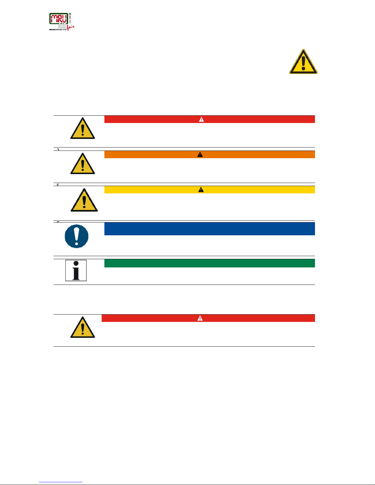
Safety declarations
In this document the safety hints will be declared as follow:
DANGER
Identifies an immediate, impending hazard that, if ignored, will
result in severe bodily injuries or death.
WARNING
Identifies an immediate, impending hazard that, if ignored, may
result in severe bodily injuries, material damage or death.
CAUTION
Identifies a possibly dangerous situation that, if ignored, may result
in minor injuries.
9.
ATTENTION
Identifies a possibly harmful situation that, if ignored, may result in
damages to the device or its surroundings.
11.
NOTE
Identifies user tips and other especially important information.
11.1. General warning
DANGER
Any maintenance action must be done only, when the atmosphere is
verified to be not explosive.
11.2. Safety Information
The following safety procedures must be followed at all times. They are significant and essential
part of this manual. Failure to follow safety procedures can result in the loss of your warranty
claims.
Biogas or other similar gases (landfill gas, bio-methane, coal seam gas etc) is containing
flammable gas component CH4 and toxic gas component as well (H2S and CO2).
Analyzers is continuously sampling a certain volume (approx 50l/h) of the sample gas, and is
venting it to ambient air.
For this reason, there are two aspects which must be considered:
1) toxicity danger of sample gas
SWG100 BIOGAS User Manual
MRU GmbH, D-74172 Neckarsulm
8 / 108
2) flammable (explosion) danger of sample gas
1) Inhaling toxic gases is harmful to health and can even cause death in some cases.
• It is the responsibility of analyzer user to ensure that person is skilled and trained
in safety aspects of gases being analyzed and procedures to follow while using this
instrument.
• Local regulations for possible exposition to toxic gases have to be known and obeyed
by the user of the analyzer
• Using a personal gas detector inside the biogas plant is highly recommended since
H2S in higher (very dangerous) concentration cannot be detected by human nose.
Only small concentrations around few ppm can be detected by human nose
• CO2 gas is heavier than air and therefore operator shall avoid working at underground
or confined spaces. Beside of that CO2 is also odorless!
• It is not allowed using the biogas analyzer in confined space or rooms
without forced ventilation.
• Sample gas exiting the analyzer will flow in the ambient air and only outdoor use
or forced ventilation rooms are suitable for using the biogas analyzer
2) Regarding flammable gases (e.g. CH4 methane) and hazardous area of operating the
instruments, user must also be able to recognize the area classification and be aware of using
the instrument there. This area classification is country specific, please observe and notice it.
• Stationary analyzers are allowed to be mounted in hazardous area zone 2 only if they
have the certificate of compliance. These instruments shall never be located in
confined places or rooms without forced ventilation.
Only trained personnel should carry out installation of stationary instrument and/or
maintenance, service and repair. Opening the stationary analyzer cabinet can expose
personnel to injuries and shocks from mains voltage!
SWG100BIO Ex. User Manual
MRU GmbH, D-74172 Neckarsulm
9 / 108
Safety regulations
The analyzer may only be used as indicated in this manual. Our analyzers are checked
according to the following regulations:
VDE 0411 (EN61010) and DIN VDE 0701 before they leave the MRU GmbH factory.
MRU technical products are designed and manufactured according to DIN 31000/ VDE 1000
and UVV = VBG 4 of the professional guilds for fine mechanics and electrical engineering.
MRU GmbH assures that the analyzer complies to the essential requirements of the legal
regulations of the member states of the electro-magnetic compatibility (89/336/EWG) and to the
low-voltage regulations (3/23/EWG).
Specific safety regulations
No part of the analyzer, or any other metal parts & accessories shall be used as electric
conductors.
The analyzer shall not be used in or under water.
The analyzer shall not be placed near or directly exposed to open fire or heat.
The analyzer shall avoid dropping.
CAUTION
Moisture or condensate, being pumped out of the condensate outlet
port can be slightly acidic.
In case of skin contact IMMEDIATELY: clean affected parts of the body.
Avoid getting liquid in eyes.
Please carefully clean all parts that come into contact with the
condensate.
11.3. Packing
Packing regulation of 12.07.1991
If your local waste facility does not accept MRU packing materials for disposal, you may return it
to MRU or our local sales representative. Packing materials returned to MRU must be returned
prepaid.
11.4. Return of hazardous waste
Waste Disposal/Returns/Warranty MRU GmbH is required to accept the return of hazardous waste such as electro-chemical
sensors that cannot be disposed of locally. Hazardous waste must be returned to MRU prepaid.
11.5. Return of analyzer
MRU GmbH is required to accept the return, for proper disposal, of all analyzers delivered after
13th of August 2005. Analyzers must be returned to MRU prepaid.

SWG100 BIOGAS User Manual
MRU GmbH, D-74172 Neckarsulm
10 / 108
11.6. MRU guarantee conditions
MRU granted of the analyzer SWG100 BIOGAS a guarantee of 12 month.
1. 6 month on MRU spare parts.
2. The term of the guarantee conditions starts as of the invoice date.
3. Excluded from the guarantee conditions are damages, which occurred by:
• Improper use.
• Improper application.
• Improper mounting.
• Deliberate or negligent destructions.
• External influence for example fall, hits, solvents, acids, gases, by normal wear or
transport damages. This applies also for defects, which are caused from high pollution
and/or moisture (condensate) in the gas route or on the sensors.
4. As well excluded from the guarantee conditions are typical consumable- and spare parts.
5. The guarantee condition denatured immediately, if no original consumable parts are installed.
The guarantee is only for original MRU consumable parts and sensors.
6. With the replacement of the type plate or the serial- number of the devices all guarantee
conditions will be invalid.
7. The service of a guarantee conditions will not enlarge the guarantee time. Demands because
of consequential damages are excluded.
8. The transport costs for round trip takes the consignor or the warrantee.
9. MRU reserves the right, to determine individual conditions or exceptions. These will be
separated informed.

SWG100BIO Ex. User Manual
MRU GmbH, D-74172 Neckarsulm
11 / 108
12. Analyzer Description
12.1. I nte nded use
The instrument is intended for analyzing the composition of biogases / biomethane / landfill
gases and determine the concentration of several components like CH4, CO2, O2 and H2S.
The instrument may optionally be equipped to monitor several sites in time sharing technique
(cyclical one by one sampling).
In particular, the instrument is not foreseen to serve as a gas detector or as a safety device.
In case of not intended use the guarantee will void. Regular controls, inspections and the
exchange from polluted and exhausted filters by the operator are also an important part of the
determinations “not determined use”- see chapter 9 regular maintenance work.
The SWG-100BIO Ex. is an extractive measuring system. It has maximal 4 sample gas inlets, to
measure the gas concentration from 4 different sample points, one by one. It has an internal
gas pump to suck the sample gas from the sampling points. After the measurement, the sample
gas is vented through the sample gas outlet (Vent).
All sample points are equipped with a flow restrictor orifice, which allows also sampling the gas
from the higher-pressure gas pipe of the engine, while limiting the maximum amount of gas in
case of internal cabinet piping leakage.
SWG100 BIOGAS User Manual
MRU GmbH, D-74172 Neckarsulm
12 / 108
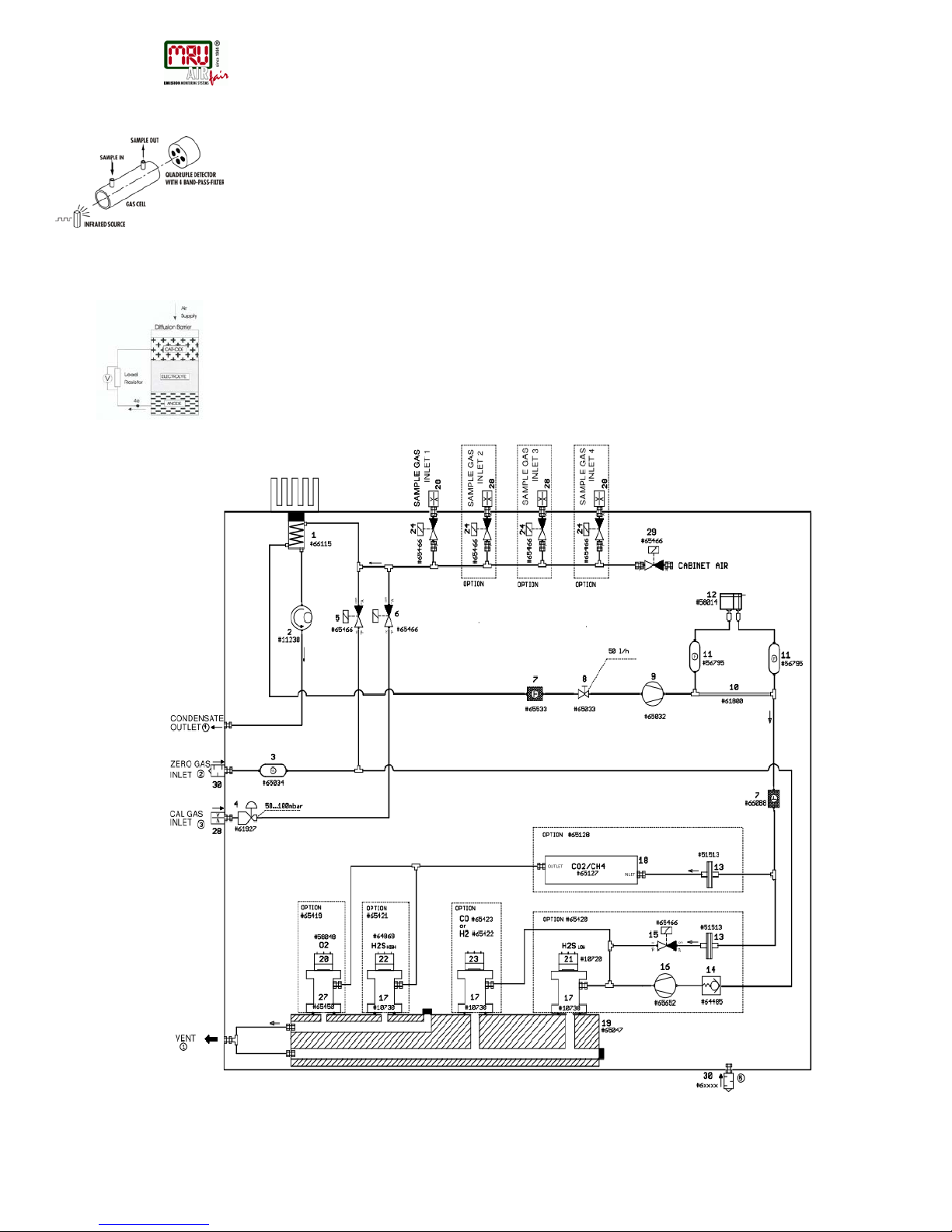
12.2. P r inciple of operation
• Sample gas from one or more sampling points is fed into the analyzer by dedicated
ports. Internally mounted electric valves select one point at a time to feed sample gas
to the analysis unit.
• The instrument is equipped with a non-dispersive infrared (NDIR) bench for analysis of
CO2 and CH4. Two separate infrared detectors for each CO2 and CH4 are included,
each operating with a different optical path length and stabilized by referring to a
reference detector. The IR source is a highly efficient and stable IR emitter, pulsed at a
frequency of several Hertz. By design NDIR technique offers good stability and
selectivity together with long life time of sensor (only limited by corrosion or dust, which
can be prevented or removed by regular servicing the instrument).
• The instrument is optionally equipped with a number of electro-chemical sensors ECS
in order to detect gas components like oxygen O2 or H2S. Those sensors offer a
reliable and effective way to detect the target gases. They are typically of limited life
time (several years) but may be easily replaced once the end-of-life is reached.
• In regular time intervals (user settable), the instrument automatically switches to purge
the sensors with fresh (ambient) air for re-adjust the zero point.

SWG100BIO Ex. User Manual
MRU GmbH, D-74172 Neckarsulm
13 / 108
12.3. Ma r king and range of application
The SWG100BIO-EX was designed for use in hazardous area with potentially explosive
atmosphere and was certificated by ATEX directive:
EX-Protection: [EX] II 3G Ex nA nC IIC T3 Gc
Certification no.: EPS 16 ATEX 1xxx X
The SWG100BIO-EX is operating in a temperature range of -20°C … +45°C with intern cabinet
heater.
The specifications of the analyzer are:
Main power supply: 230 VAC / 50 Hz
Power consumption: 36 VA
Protection class: IP65
Fuses: 230 VAC/ 50Hz / 6 A
Data output interface: 4…20 mA / analog outputs
RS485 Modbus RTU
12.4. Possible applications and analyzer options
The bi ogas analyzer SWG100 is the industrial measuring solution to be used at all hazardous
zone 2 areas of::
• biogas (anaerobic digestion) plants
• cogeneration heat and power engines (CHP)
• municipal or industrial waste water treatment sites
• coal seam gas sites (coal bed methane)
• food and animal waste processing plants
• biomethane (gas to grid) plants
• landfill sites
12.5. Features
This analyzer can be equipped with additional options and/or additional accessories to full fill
multiple other measuring tasks such as
• H2S
low measurement with protected EC cell using cutoff solenoid valve and air
purge pump
• H2S
high measurement with EC cell
• H2 measurement with EC cell
• CO measurement with EC cell
• Multiple sampling point switchover from 2x up to maximum 4x sites
• Module with 4 channel analog outputs/inputs 4-20mA, with 2x “fail safe” alarm
relays
• Converter module of RS485 into Profibus
• Cabinet heater for freeze protection
Ask our sales representatives for available options and accessories or check out our MRU
website.

SWG100 BIOGAS User Manual
MRU GmbH, D-74172 Neckarsulm
14 / 108
13. Overview of the SWG-100BIO Ex
13.1. S cope of supply and delivery
The delivery contains the follow components:
• SWG-100BIO Ex analyser, with a stainless steel case.
• A stainless-steel thread filter for the zero gas inlet, with a G1/8 inch male thread.
• Flow restrictor orifices for the sample gas inlets, with a G1/8 inch female thre ad. The
number of flow restrictors is depended from the number of gas sample inlets.
• A fitting for the gas outlet (vent), with a G1/4 inch male thread.
• Mounting material.
• Optional: Flame arresters for the sample gas inlets, with a G1/4 inch male thread.
13.2. Material required for the installation (not scope of supply)
Material for tubing or hosing the sample gas inlets and outlet.
• For the sample gas inlets: Flexible PTFE tube or stainless steel tubing with a
diameter of 4/6 mm. It could be necessary to install a heated sample line on the tubes,
to protect the sample gas from freezing.
• For the sample gas outlet (Vent): Flexible PTFE tube with a diameter of 8/10 mm. It
could be necessary to install a heated sample line on the flexible tube, to protect the
vent gas pipe for freezing.
• For the condensate outlet: Flexible tube with a diameter of 4/6 mm. It could be
necessary to heat the condensate tube to prevent that the condensate for freezing.
Power supply lines and signal lines
• Cable for power supply: Cable type: H 07 RN-F 5 G 0,75 mm²
• Signal lines for 4…20 mA analog outputs.
• Signal lines for Modbus RTU digital transfer.
SWG100BIO Ex. User Manual
MRU GmbH, D-74172 Neckarsulm
15 / 108
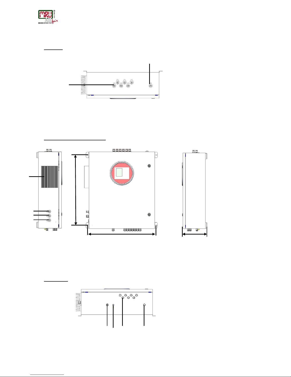
13.3. Dimensions and views of the analyser
Top view:
Front view / left view / right view
Bottom view
642 mm
630 mm
223 mm
1 2 1 2 3 4 1
2 3 4
Reference:
1. Sample gas inlets G1/8 inch female thread.
2. Sample gas outlet G1/4 inch female thread
Reference:
1. Heat sink of gas cooler unit
2. Calibration gas inlet G1/8 inch female thread
3. Zero gas inlet G1/8 inch female thread
4. Condensate outlet G1/8 inch female thread
Reference:
1. Cable gland M16 for power supply
2. PE bolt for earthing cable
3. Cable gland M16 for I/O modules
4. Breather drain
SWG100 BIOGAS User Manual
MRU GmbH, D-74172 Neckarsulm
16 / 108
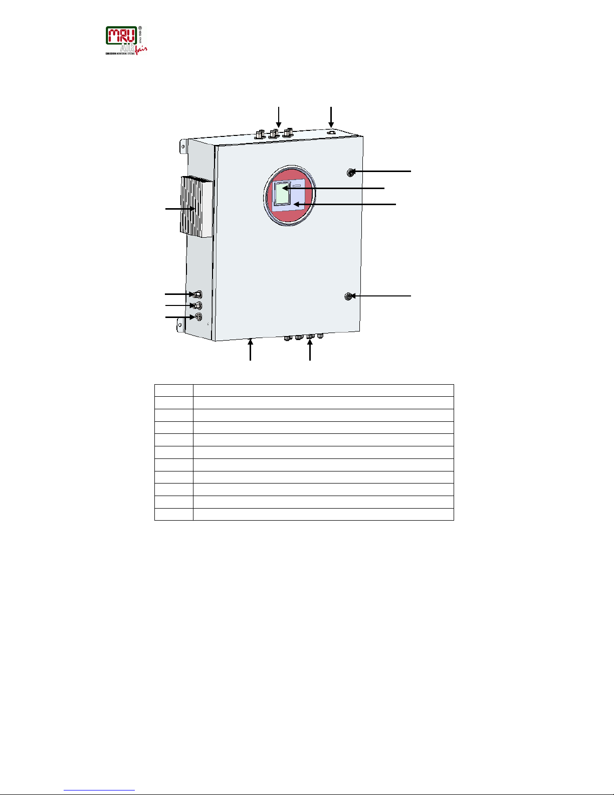
13.4. P osition of the gas in and outlets
1
Display (color, with backlight)
2
Keypad
3
Sample biogas inlet ports (1 to max 4 ), female G1/8” threads
4
Cabinet lock
5
Inlet cable glands M16 for I/O modules
6
Inlet cable gland M16 for mains power supply
7
Heat sink for gas cooler unit
8
Condensate outlet port, female G1/8” thread
9
Zero gas inlet port, female G1/8” thread
10
Calibration gas inlet port, female G1/8” thread
11
Vent outlet port, female G1/4” thread
1
2
3
4
4 5 6
7
11
8 9 10
SWG100BIO Ex. User Manual
MRU GmbH, D-74172 Neckarsulm
17 / 108
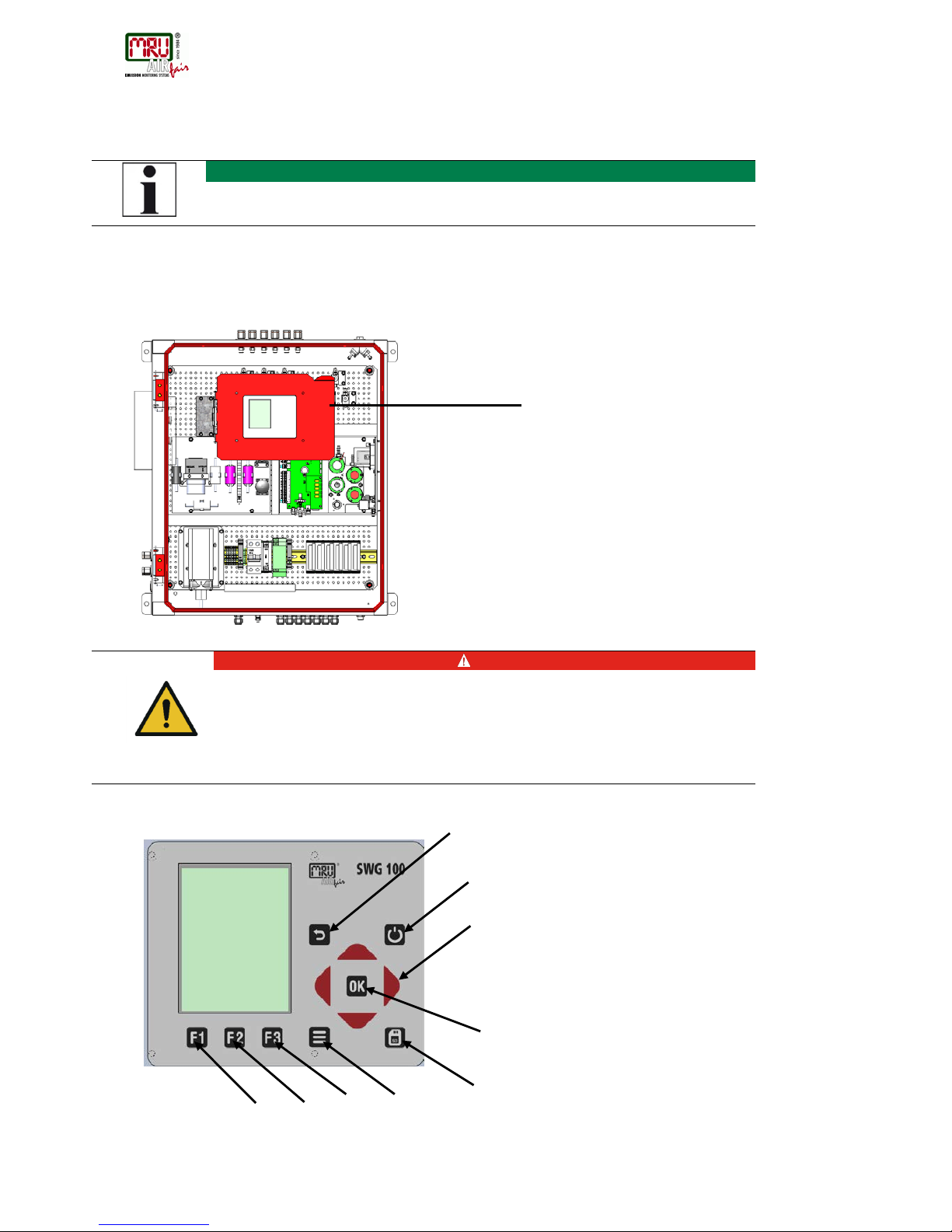
13.5. Operating unit: Display and keypad
14.
NOTE
Operation of the keypad is intrinsically safe.
All commissioning can be carried out with the control-unit.
The operating-unit can only be operated when the cabinet door is open.
DANGER
Explosion hazard
In case of system alarm, after analyser has auto-shut-
off itself, the
cabinet might contain an explosive atmosphere. Any ignition source
must be avoided when opening the door.
Keypad for operation of control unit.
1 2 3 4 5
6 7 8
9
Control unit
SWG100 BIOGAS User Manual
MRU GmbH, D-74172 Neckarsulm
18 / 108
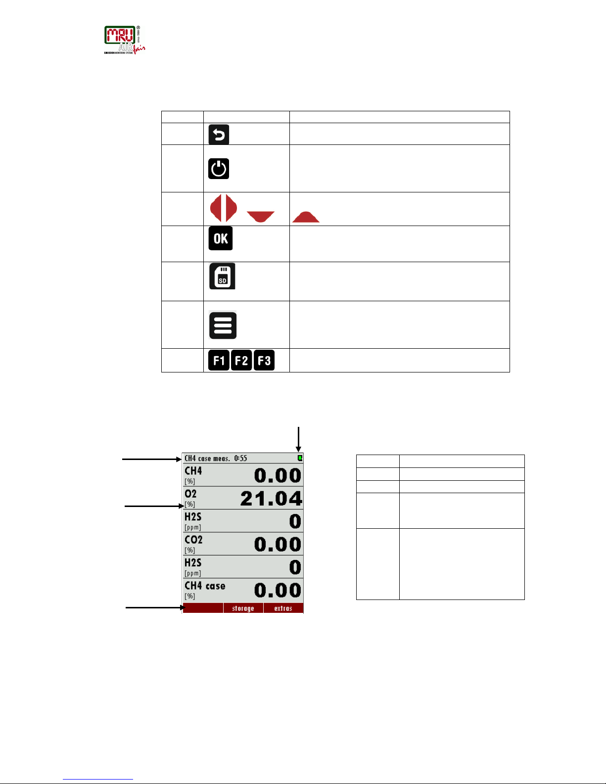
All information required to operate the analyser is displayed as shown below.
Number
Symbol
Description
1
ESC : abort or return to the menu above
2
Prepare Power-Down: Press this key before you
disconnect mains. The analyser will store changed user
settings and other operational data and will purge the
sensors 3 , , ,
Arrow keys: context dependent functions, e.g. scroll in
between lines, change values, change view.
4
OK : confirmation key, select a marked menu point.
5
Screen shot : press this key in order to store a screen
shot of the current display contents onto the SD card.
6
Menu key: Will show all available functions in the
window that is currently in use – also those which have
an individual key on the key pad like the printer and the
three function keys.
7-9
Function Keys : Activates the functions seen on the
display (2 function key bar)
All information required to operate the analyser is displayed as shown below.
Number
Function
1
Menu bar
2
Function key bar
3
Display panel
- Menu
- Measurement value,
4
SD-Card in the slot
- Indication green readand write access
- Indication yellow only read
access (SD-Card write
protected)
1 2 3
4
SWG100BIO Ex. User Manual
MRU GmbH, D-74172 Neckarsulm
19 / 108
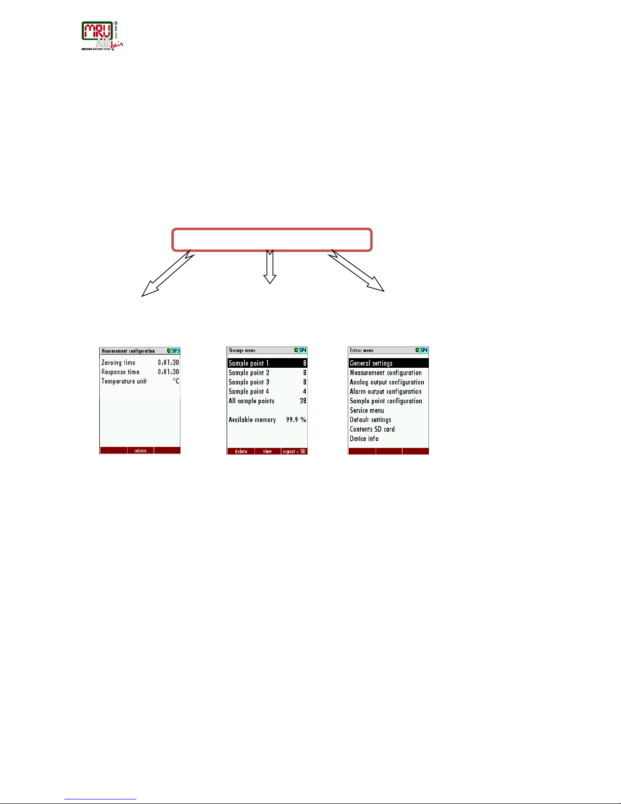
14.1. Measurement menu
The measurement menu is the main root of the menus. Here you can see the current
measurement values, the current sampling point number and the status of the zeroing process
while it's active. Via pressing the function keys F1-F2-F3 you can reach other menus:
- F1: Menu Sample Point Switching
- F2: Menu Storage
- F3: Menu Extras
Menu Memory all tasks for the management of the data memory available.
Menu Extras all the other available tasks – for management and customizing your
analyzer.
Please read chapter 5 for
details.
Please read chapter 5 for
details.
Please read chapter 5 & 6
for details.
No matter which menu is currently active you will return to the measurement menu by pressing
the ESC key several times.
SWG 100 BIOGAS
SWG100 BIOGAS User Manual
MRU GmbH, D-74172 Neckarsulm
20 / 108
15. Explosion protection systems of SWG100BIO-EX
The explosion protection of SWG100 Bio-EX is based on the nA and nC type of protection as
indicated in the ATEX declaration. Following aspects have to be followed.
Any action not in line with the guidelines below may violate the explosion protection of the
SWG100 BIO-Ex and may results in danger and explosion hazard
WARNING
The following chapter explains with which protection systems
the SWG100BIO-
Ex. is equipped. If one of the explained
protection systems is triggered, the user must do the following
actions to prevent an ignition inside the analyser cabinet.
• Only staffs with a “hot permit” are allowed to restart the
analyser in service.
• The staff must have a certified flammable gas detector to
monitor the ambient atmosphere.
• The cabinet door shall not be opened by force in order to
prevent ignition sparks.
•
The entire cabinet must be checked for absence of
flammable gas with a certified combustible gas detector.
• It is not allowed to restart the analyser in service, until the
cause of system alarm is remedied.
•
Exchange disconnected flexible tubes. Never use
exhausted tubes again.
15.1. Electrical components
All components in the SWG100 BIO-EX are selected and qualified to meet the requirements of
the given type of protection (nA or nC). Make sure that any change to the instrument during it’s
life time are in line with the requirements of this type of protection. No change to the wiring or
change of components are allowed without prior information about the impact on the type of
protection of these changes. Always ask feedback of MRU for the intended changes.
15.2. IP 65 cabinet
The SWG100BIO-Ex. has an IP 65 cabinet. The cabinet prevents explosive gases and dust to
penetrate inside. Prevention from dust is a basic requirement to the type of protection.
Therefore, it is required to always operate the instrument with the door being closed. Perform a
visual inspection in regular time intervals to verify the housing and the seals of the door and
window are not damaged.

SWG100BIO Ex. User Manual
MRU GmbH, D-74172 Neckarsulm
21 / 108
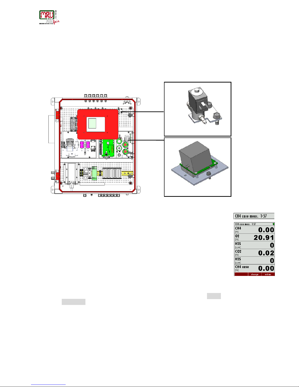
15.3. CH4 measurement of inside cabinet
While the components internal to the instrument are verified to meet the type of protection, it is
nevertheless required to monitor the cabinet to prevent explosive atmosphere being present.
Therefore SWG100 BIO-EX implements a regular monitoring of the CH4 content inside the
cabinet with the help of the CH4-NDIR bench used for biogas measurement.
In case an explosive atmosphere is detected inside the cabinet, the SWG100BIO-EX outputs an
alarm signal to the remote power supply box, which interrupts the power supply of the full
instrument.

SWG100BIO Ex. User Manual
MRU GmbH, D-74172 Neckarsulm
23 / 108
Desciption of the CH4 cabinet monitoring
The main parts of the system are following:
• The CH4/CO2 NDIR- bench.
• A solenoid valve, which feeds the atmosphere inside the case to t he CH4/CO2 NDIR
bench.
The figure below shows the position of the two components.
• The CH4 cabinet measurement is inforced after each air purging phase / zero point.
This phase takes 2 minutes and is called 'CH4 case measurement'. During this phase
the menu indication bar will indicate 'CH4 case meas.' and a count-down starts.
• During this phase, all solenoid valves are closed and the solenoid valve, which feeds
the gas from inside the cabinet, will open. The first 90 seconds of the CH4 monitoring
is used to feed the inside cabinet atmosphere to the NDIR bench. Only in the last 30
seconds the CH4/CO2 NDIR- bench detects the CH4 concentration. During this
time the measured CH4 values will be shown also as life values.
• The CH4 concentration is displayed as CH4 % concentration as well as CH4
concentration in % LEL in the measurement menu (see screenshots below).
• If the CH4 concentration rises over an user defined value, an alarm will be triggered for
2 minutes. After the 2 minutes the analyser will power down to prevent an explosion.
• The CH4 alarm threshold can be set in the general menu (find on the path: EXTRAS /
GENERAL MENU).
• If the user must perform maintenance works on the analyser and the alarm appears, it
is possible to delay the power down for 1 hour to max 2 hours. The alarm menu can be
closed with the key F1 or ESC. The alarm is still active, the user will see a flashing red
'OFF' on the menu indication bar.
Solenoid valve for CH4 monitoring
CH4 / CO2 NDIR-bench
Menu screen in the „CH4
case meas.” mode

SWG100 BIOGAS User Manual
MRU GmbH, D-74172 Neckarsulm
24 / 108
•
Self test of the CH4/CO2 NDIR- bench
The CH4/CO2 NDIR-bench being a part of the SWG100BIO-EX protection system, is requir ed
to be monitoring itself. In case the bench is supposed to be not working correctly, the alarm
output is activated as well, which will lead to a power down of the instrument.
This self test is performed regularly and intrinsically by the biogas sample gas measurement
itself. The analyser detects the CH4 concentration on all installed sample gas inlets. If the CH4
concentrations of all inlets are below 5 Vol.%, the alarm is triggered. The user has the
possibility to manually delay the power-down in 1 hour intervals (max. 24 hours), in case the
missing CH4 is known to be due to the sample gas composition. Do not delay the alarm if there
is any doubt on the NDIR bench’s performance. The alarm is still active, the user will see a
flashing red 'OFF' on the menu indication bar.
In case the user needs to pause the self test supervision for a limited time interval, this can be
done for a couple of hours (min.2:00:00 max.24:00:00) in order to prevent a switch-off alarm. To
pause the function, select to the path: EXTRAS / CH4 SENSOR S UPERVISION. The following menu will
appear. With F3 the supervision function can be switched off and on. In the screen a countdown
appears. This countdown shows when the paused CH4 sensor supervision will restart. With the
right/ left arrow keys the countdown can be set up until 24 hours.
After power-on the CH4 sensor supervision will start as soon as all sample gas inlets have been
measured once and not earlier than 1 hour operation.
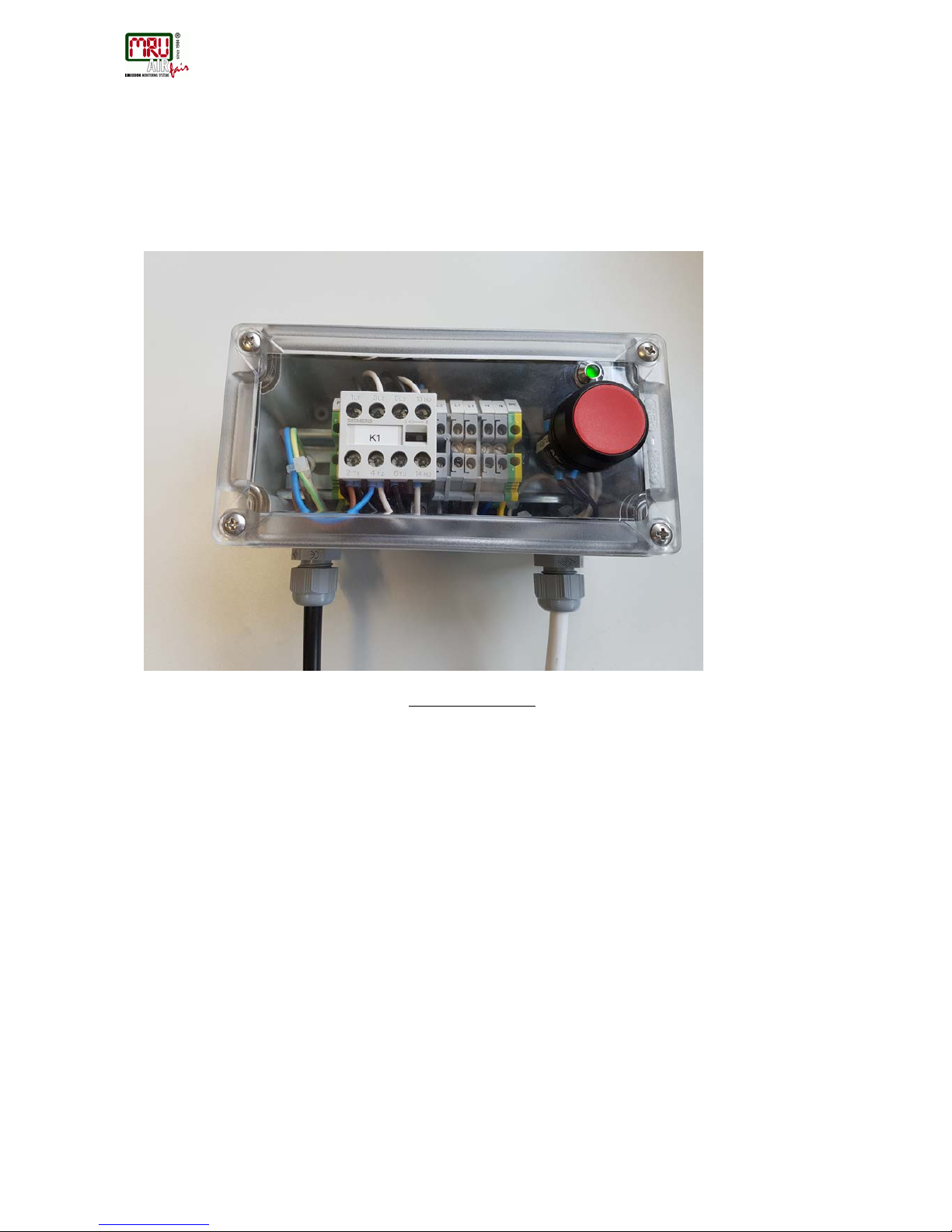
15.4. Remote Power Supply Box
When the SWG100BIO-EX outputs an alarm (due to internal CH4 detected or due to failed self
test) it is required to switch off the instrument completely by means of an external power supply
box, which shall be located in safe area, in the power supply distribution cabinet.
Screen after a delay was added
Right / left arrow keys
to set the
countdown up or down.
General menu: Menu-
point to set the LEL Level
Switch off alarm. The user has 2 minutes
before the SWG100BIO-Ex power down.
SWG100BIO Ex. User Manual
MRU GmbH, D-74172 Neckarsulm
25 / 108
The Remote Power Supply Box as optionally supplied by MRU, has a switch-off contactor (K1),
with 3 m ake contacts (normally open). The power contactor K1 is activated after the analyser is
powered on by pushing the power-on button until the green LED is light-on. In case of an
SWG100BIO-EX alarm, the power contactor K1 is deenergized. The circuit diagram shows the
correct wiring of the power co ntact or inst a lled in the remote power supply box.
For more information see chapter 20.3
The circuit diagram of above pictured device must be implemented by user as part of the safety
concept.
User can either use the remote power supply box as offered by MRU, or install inside the power
distribution cabinet a similar circuit (see diagram in chapter 20.3) using a power contactor and
push-start button.

SWG100BIO Ex. User Manual
MRU GmbH, D-74172 Neckarsulm
27 / 108
16. Sample Gas measurement
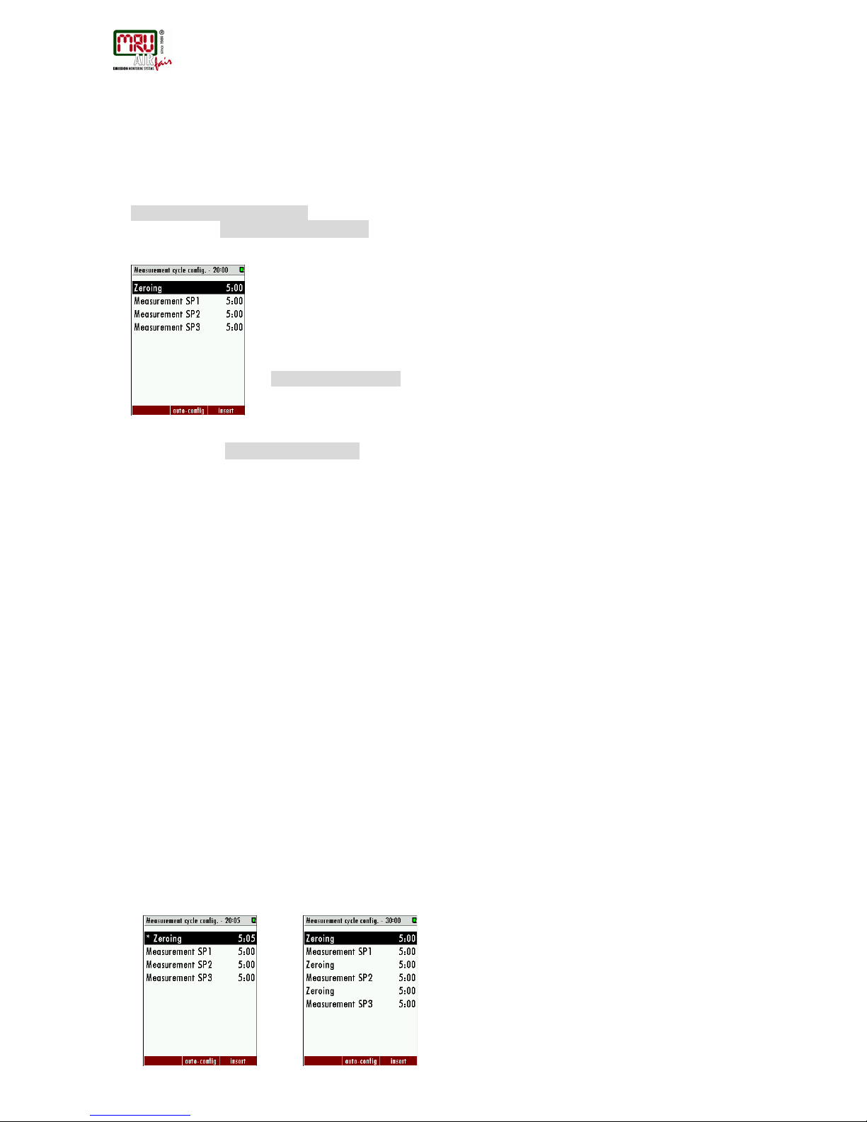
16.1. Cycle configuration
Path and default setting
EXTRA/ MEASUREMENT CYCLE CONFIG.
When the menu “MEASUREMENT CYCLE CONFIG.” is selected the user definable setting for the measurement cycle will
appear (see screenshot below).
General information
The menu point “CYCLE CONFIGURATION” allows the user to configure an individual measurement cycle. Every
installed sample point can be configured. For the configuration the user has the following phases, which can be
selected:
• Zeroing.
• Purging.
• Stand-by.
• Measurement SPx (SPx stands for Sample point 1, 2…).
The configuration is performed with the three function keys F1, F2 and F3.
• F1: Delete a phase.
• F2: Make an Auto-config.
• F3: Insert a new phase.
• OK: View/change phase details
• Left/right: Change the phase type.
Auto configuration
With F2 the “Auto-config.” can be selected. The user can select one of two default cycle configurations.
• One zeroing / cycle.
• One zeroing / sample point.
The first program is for applications where the different measurement points have almost the same gas
concentrations. The zeroing is not necessary at every change of the measur eme nt SPX.
The second program is for applications where the different measurement points have different gas
concentrations. A zeroing is recommended after every measurement point change.
The screenshots below show the “One zeroing / cycle” and “One zeroing / sample point” in comparison.
Screenshot shows default setting, when
the „MEASUREMENT CYCLE CONFIG.” will be
started the first time.
The two auto-configurations, which can be selected.
SWG100 BIOGAS User Manual
MRU GmbH, D-74172 Neckarsulm
Depending on the analyser type, the first or the first and second phase cannot be deleted, deactivated or moved
to another position.
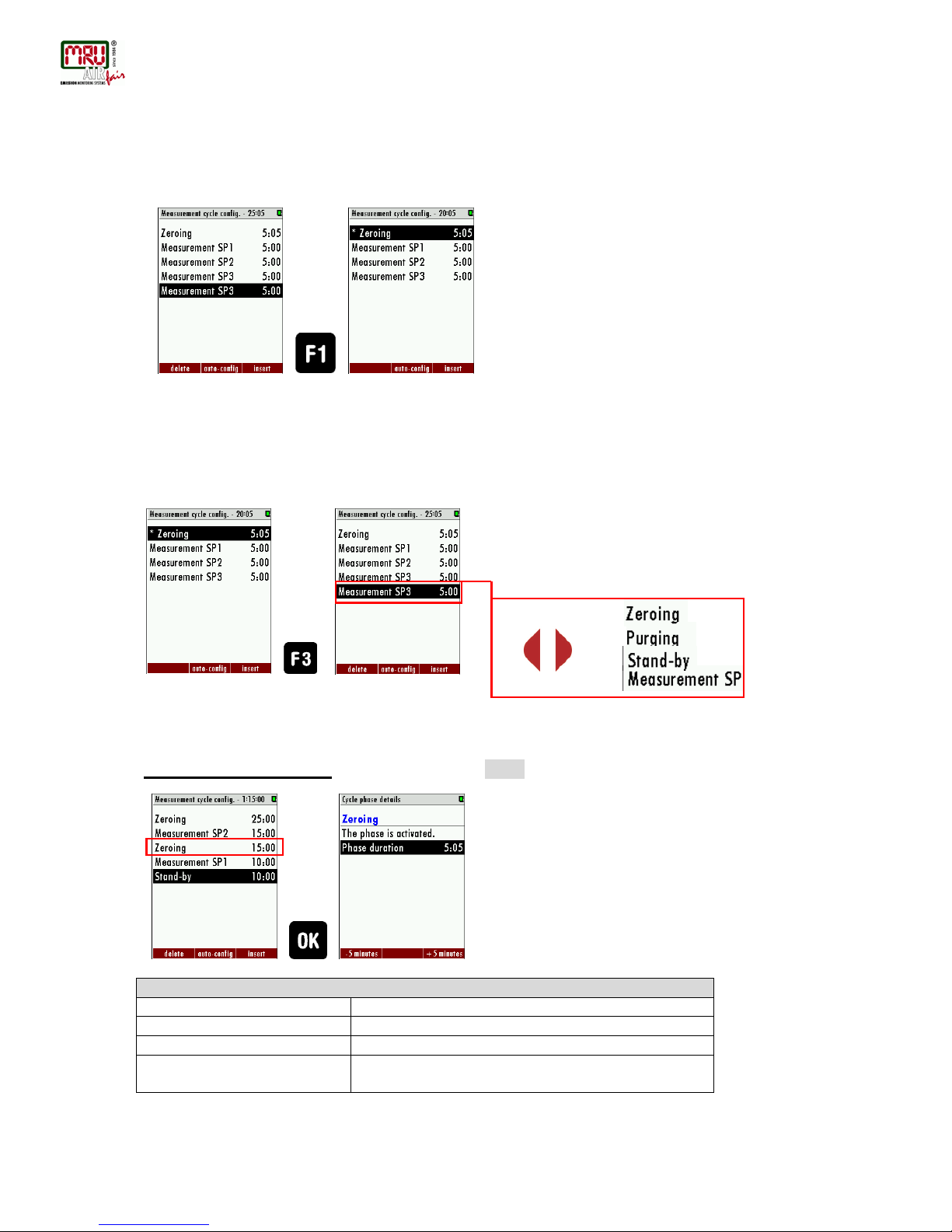
Delete a phase
With F1 a phase can be deleted. To do this, select the phase, which should be deleted and press F1.
Insert a phase
With F3 a new phase is inserted in the measurement cycle. With the right/left arrow keys the different phase
types can be selected.
In the title-bar the entire cycle time is shown. It is called “Measurement cycle config.”
With OK the “Cycle phase details” can be shown and changed.
Configuration of the phase details
In this chapter the different cycle phase details will be explained.
Zeroing (Cycle phase details): In the cycle phase detail “ZEROING” the zeroing time can be configured.
ZEROING
Measuring site valves
Valves closed
Zeroing valve
Valve open
Duration
2min to 1 h
Recommendation
5min., in general not to be changed by user as depending
only on analyzer internal setup
+
=
Screenshot shows how a
phase can be deleted. In
this example the last phase
“Measurement SP3” is
deleted.
SWG100BIO Ex. User Manual
MRU GmbH, D-74172 Neckarsulm
29 / 108
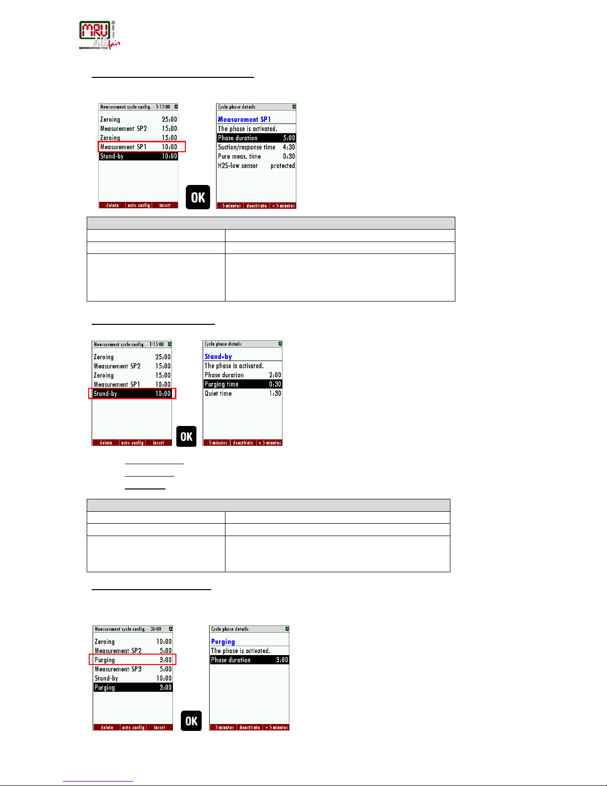
Measurement SPX (Cycle phase details): In the cycle phase details of “Sample point X” the measurement time
and the suction delay can be configured. Each sample point can be configured individually. In the cycle phase
details the following times can be set:
MEASUREMENT SPx
Measuring site valves
Valve of selected site is open, others closed
Zeroing valve
Valve closed
Duration
Phase duration: 2 min. to 24 h
Suction/response time: 30 sec. to 1h
Pure measurement: calculated
H2S-low: Activated/protect (Optional)
Stand-by (cycle phase details): In the cycle phase details “Stand-by” the sleep mode time can be configured. In
the cycle phase details the following times can be set:
• Phase duration: Entire Stand-by time (Purging time + Quiet time = Phase time).
• Purging time: The time, to purge the analyser with ambient air, through the zero gas inlet.
• Quiet time: The time, where the analyser is in the pure stand-by mode.
STAND-BY
Measuring site valves
Valves closed
Zeroing valve
Valve closed
Duration
Phase duration: 2 min to 24h
Purging time: 30 sec. to 1h
Quiet time: calculated
• Purging (cycle phase details): The purging is a separate configuration point to purge the analyser with ambient
air through the zero gas inlet. It can be helpful, if the analyser must switch between a sample point with different
sample gas concentrations.
SWG100 BIOGAS User Manual
MRU GmbH, D-74172 Neckarsulm
PURGING
Measuring site valves
Valves closed
Zeroing valve
Valve open
Duration
30 sec. to 1 h
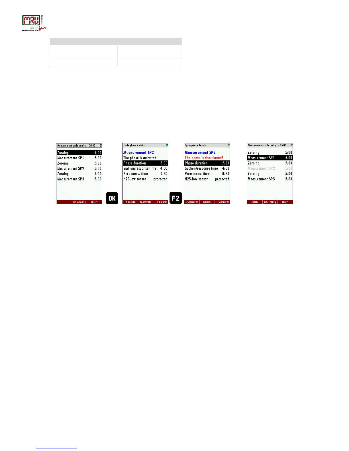
Activated/deactivated a phase
The user has the opportunity to deactivate a phase in the measurement configuration cycle. This could be
necessary for example if a sample point is temporarily not in use. The activation and deactivation of a phase can
be done in the cycle phase details of the concerning phase.
Example for the deactivation of a phase
In this example the “Measurement SP2” will be deactivated. The deactivated phase is grey out.
=

SWG100BIO Ex. User Manual
MRU GmbH, D-74172 Neckarsulm
31 / 108
Or
F1/F3
Or
F1/F3
Or
F1/F3
Example for a measurement cycle configuration
In this chapter an individual measurement cycle should be created with the features described
at the chapters below.
The measurement cycle should have the following sequence:
Following points must be done to configure the individual measurement cycle:
1. Open the measurement cycle config. menu: Path: EXTRA/ MEASUREMENT CYCLE CONFIG.
2. The default measurement cycle will appear. Open the cycle phase detail of the first
zeroing and adjust the phase duration at 25 min.
3. Leave the cycle phase detail and select the second point. Switch with the left/right
arrow keys until the measurement SP2 is selected.
4. Open with the OK key the cycle phase detail of the measurement SP2. Adjust the
duration-phase at 15 min. and the suction/response time until the pure meas. time has
the value of 3 min. Use for this operation the arrow keys.

SWG100 BIOGAS User Manual
MRU GmbH, D-74172 Neckarsulm
32 / 108
Or
F1/F3
Or
F1/F3
Or
F1/F3
Or
F1/F3
5. Leave the cycle phase detail and select the next phase. Select with the left/right
arrow keys the phase “zeroing” and go in the cycle phase detail. Adjust the phase-
duration at 15 min. and leave the cycle phase detail.
6. Switch to the next point and select with the left/right arrow key the measurement
SP1. Go in the cycle phase detail of the measurement SP1. Here adjust the durationphase 10 min. and the pure measurement time: 5 min.
7. At last push F3 key for insert a new phase and select with the left/right arrow key the
“Stand-by” phase. Go into the cycle phase detail and adjust the Purging time at 3 min.
and the Quiet-time at 10 min.
Leave the menu and safe the adjustments. The individual configuration is done.
16.2. H2Slow sensor protection (optional)
The instrument may be optionally equipped with a H2S
low
sensor. As this sensor typically shows
limited life time when experiencing high H2S concentrations, some precautions are taken to
protect the sensor:
• The instrument is equipped with a cut-off solenoid valve and air purge pump to protect
the H
2Slow
sensor, without impacting the results of all other sensors.
• The purge unit is always activated after 3-10 minutes of active sensor measuring time.

SWG100BIO Ex. User Manual
MRU GmbH, D-74172 Neckarsulm
33 / 108
• The measuring time of the H2S
low
sensor may be limited to less than 10 minutes by
user setting
• The H
2Slow
sensor may optionally not be included in all measuring cycles of sampling
points. Instead the user may configure that the H
2Slow
sensor is active only added at
some of the measurement cycles.

SWG100 BIOGAS User Manual
MRU GmbH, D-74172 Neckarsulm
34 / 108
17. Analyzer mounting and installation
17.1. Content of y our or der
Your analyzer is delivered in a carton box and is protected with special edged protectors.
Please do preserve the packing of your analyzer, for possible back shipment.
17.2. I nstallation rules to guarantee explosion protection
The SWG100BIO-Ex. has an ATEX Class 2 certification. To guarantee, that the analyser can be
operated safely in this area, please follow the rules during the mounting and the operation of
the analyser.
17.3. Prerequisites for installation
DANGER
Explosion hazard
Before start the mounting and installation work, detect the atmosphere
with a certificate gas detector.
CAUTION
Only educated staff should mounting the analyzer on the stack.
NOTE
Important
The mounting should be done in pairs.
A measurement point must conform some criterions:
• The measurement place must be safeguarding and easily accessible.
• The measurement place must have enough space for installation and
maintenance works.
• The place should be protected for direct sunlight, rain and squalls.
• The area around the analyzer must have enough space.

SWG100BIO Ex. User Manual
MRU GmbH, D-74172 Neckarsulm
35 / 108
17.4. S teps for the mechanical mounting and installation
The graphic below shows the single steps, which must be done to mount the SWG100BIO Ex.
analyser correctly into the application
Mounting the analyser on a wall or a steel rack
Installation of the power supply
Installation of the sample gas tubing
Installation of the Modbus RTU (optional)
Installation of the I/O modules
Installation of the external switch-off circuit

SWG100 BIOGAS User Manual
MRU GmbH, D-74172 Neckarsulm
36 / 108
17.5. Mounting the analyser on a wall or steel rack
The analyzer can be mounted indoor or outdoor. The device is designed for the mounting on
wall or on steel rack. The follow sketch shows the dimensions, which the analyzer needs for the
correct mounting.
DANGER
Explosion hazard
Before start the mounting and installation work, make sure to have a
“hot permit” and monitor at all time the ambient atmosphere with a
certified flammable gas detector.
CAUTION
Only operate the analyzer in an upright position. Only power the
device up after it is correctly mounted.
General installation rules
• Mount the device on a solid wall or steel rack.
• Be sure, that the air circulation is not obstructed.
• Let enough room for the tubing or piping.
For outdoor installation
Ensure that the analyzer is mounted on a rain and sun protected place (weather shade).
4x M8 bolts
(by user)
642 mm
630 mm
D:4x 10,20 mm

SWG100BIO Ex. User Manual
MRU GmbH, D-74172 Neckarsulm
37 / 108
For indoor installation:
Ensure that the analyzer is installed on a dry and clean place. Be sure that the room is
permanently vented with fresh air (forced ventilation).
Connect the VENT gas-outlet of the device to ambient by using adequate tube with min Ø8mm
ID.
17.6. Corr ect tubing of the SWG100BIO-Ex
The analyzer uses two different fitting diameters. The position and the diameters of the different
connectors will be shown in the sketch below:
DANGER
Explosion hazard
Before start the mounting and installation work, make sure to have a
“hot permit” and monitor at all time the ambient atmosphere with a
certified flammable gas detector.
CAUTION
Do not cover the breather drain!
18.
NOTE
All connectors of the analyzer use female threads.The analyzer may be
connected by tubing or piping.
Distance, which should be fulfilled
Min. 40 cm
Min. 30 cm
Min. 50 cm
Do not cover the
breather drain.

SWG100 BIOGAS User Manual
MRU GmbH, D-74172 Neckarsulm
38 / 108
Top-side
On the top of the analyzer are the sample gas-inlets. Sample gas inlet 1 is the default gas inlet
port. The analyzer may be equipped with up to 3 additional sample gas inlet ports from different
sampling sites. The following sketch shows the position of the different sample gas inlets.
18.1. Flow restrictor orifice (#65114)
To measure any biogas applications, the analyzer can be equipped with a flow restrictor orifice
(see picture).
Picture: Flow restrictor orifice with intern filter.
Information
The copper seal of the nozzle is intended only for single use.
Connection the flow restrictor orifice with the gas inlets
Fitting type: G 1/8 inner ISO parallel thread for tubing with 6/4 mm flexible tube.
Information
Use PTFE strips to tighten the fitting inside the thread!
The flow restrictor orifices are installed on the sample gas inlets and on the calibration gas inlet.
G1/8“ out ISO parallel thread
G1/8“ ISO parallel thread
Sinter filter
O-ring
Nozzle
Male connector G1/8“

SWG100BIO Ex. User Manual
MRU GmbH, D-74172 Neckarsulm
39 / 108
Left-side
CAUTION
Be sure, that the heat sink has enough distance to the next wall.
CAUTION
Be sure that the Zero gas inlet feeds fresh, clean air.
Heat sink:
Do not cover the heat
sink from the gas
cooling- unit.
1
2
3
1
Calibration gas inlet
Fitting: 1/8 in. ISO parallel thread.
Zero gas inlet:
Fitting: 1/8 in. ISO parallel thread.
Condensate outlet (Option:
65408)
Fitting: 1/8 in. ISO parallel thread.
Reference:
1. Fitting for PTFE tubing 4/6 mm G1/8” thread
2. Flow restrictor orifice G1/8” thread.
3. Zero gas filter G1/8” thread

SWG100 BIOGAS User Manual
MRU GmbH, D-74172 Neckarsulm
40 / 108
18.2. I nstallation of the power supply
DANGER
Explosion hazard
Before start the mounting and installation work, make sure to have a
“hot permit” and monitor at all time the ambient atmosphere with a
certified flammable gas detector.
DANGER
Electric shock.
Electricity may cause death. Only educated staff should be allowed for
mounting and installation job.
100-230 Vac/ 47-60 Hz/ 300W
Fuse 4A slow (by user)
N
L
PE
Pre-fuse
N
L
PE
Cable gland (M16):
For cables with Ø 3,5-10 mm.
Remote power supply circuit
to guarantee power down the analyser in
case of hazard. (See chapter
20.3)
K2 switch off relay
G5
G5
2
~
~

SWG100BIO Ex. User Manual
MRU GmbH, D-74172 Neckarsulm
41 / 108
18.3. Installation of the external switch-off circuit
The remote power supply box itself is not explosion protected at all. Therefore it must be
installed in safe area.
WARNING
Safety installation
The external electric contactor K1 is a part of the safety installation. It is
required to be installed by user when power supplying the analyser.
The circuit diagram below shows the correct wiring of the remote
power supply box.

SWG100 BIOGAS User Manual
MRU GmbH, D-74172 Neckarsulm
42 / 108

SWG100BIO Ex. User Manual
MRU GmbH, D-74172 Neckarsulm
43 / 108
18.4. Conne ction of the I/O module
DANGER
Explosion hazard
Before start the mounting and installation work, make sure to have a
“hot permit” and monitor at all time the ambient atmosphere with a
certified flammable gas detector.
DANGER
Electric shock.
Electricity may cause death. Only educated staff should be allowed for
mounting and installation job.
NOTE: analog output current 4-20mA load resistor is max. 500Ohm
analog output does not require power supply since it is sourcing the current
alarm relays Out1 and Out2 contacts are “fail safe” type:
open contact in case of alarm or power failure
closed contact for normal operation
Cable glands (M16):
For cables with
Ø 3,5-10 mm.
Signal cable
for I/O modul
RS-485
Out 1
Out 2
Out 3
Out 4
Out 1
Out 2
20mA Alarm
+ + +
-
- - -
4
3
2 1 4 3 2
1
+
+
-
+
In +/- 30V
12V
0V
PT1000
TH-
TH+
Temperature input
In 20mA

SWG100 BIOGAS User Manual
MRU GmbH, D-74172 Neckarsulm
44 / 108
Plug connector definition:
WARNING
Electric voltage
Power the system down and protect for reconnecting, before start maintenance
work.
Slit screws
Stripping length: 7 mm
Tightening torque min.-max.: 0,5-0,6 Nm
Conductor cross sections, which can be used:
Type of electric line
Conductor cross section min.-max.
Solid
0,2-2,5 mm² (30-12 AWG)
Stranded
0,2-2,5 mm² (30-12 AWG)
Solid with ferrule (with/ or without plastic)
0,25-2,5 mm²
Information for cables, which go through the cable gland M16:
It is recommended to use only electric lines with ferrules.

SWG100BIO Ex. User Manual
MRU GmbH, D-74172 Neckarsulm
45 / 108
19. Power up and commissioning the analyser
After installation of the analyzer few steps should be processed in order to operate the
instrument properly.
The graphic below shows the few steps, which should be done, to power up the analyser
correctly.
START
Supervise the atmosphere with an external certified combustion gas
detector.
Open the case door of the analyser
Power up the circuit breakers
Press the power switch from the remote power supply box.
The analyser will start.
Make the analyser commissioning on the operation unit.
- Language
- Date and time of the instrument
- Configure sample points
- Configure analog in and outputs of the I/O modules
- Configure the alarm relays
- Configure the Modbus RTU.
CLOSE and LOCK the cabinet door of analyser
END OF PROCESS

SWG100 BIOGAS User Manual
MRU GmbH, D-74172 Neckarsulm
46 / 108
19.1. Power up the analyser
1. Open the case door of the analyser.
2. Power up the circuit breaker. See figure below.
3. Press the power switch of the remote power supply box. Wait until the system is ready
for operation. The green LED on the remote power supply box will glow .
4. The analyser will start and firmware will boot. Wait until the first Self-Test is completed.
Power up the circuit breaker.
Q1
Q1
L
N
Press for 3 sec.

SWG100BIO Ex. User Manual
MRU GmbH, D-74172 Neckarsulm
47 / 108
19.2. Check country and language
Important note:
In case the analyzer shows a language, you don't understand, you ma y swap the language to
English by pressing the menu key and selecting the function 'Set English language'.
Use the menu EXTRAS – GENERAL SETTINGS.
The analyzer will automatically set some country-typical things like the language, the date
format, the temperature unit, the daylight-saving time function and the CSV-export settin gs .
19.3. Che ck date and time of the instrument
The analyzer stores automatically measurement values including timestamps. Therefore, the
instruments' system clock should be set correctly.
Use the menu EXTRAS – GENERAL SETTINGS – DATE & TIME.
In case the date & time is not correct, press the key F2=modify, change date & time and then
press the key F2=store.
Note:
According to the selected country (see previous chapter) the analyzer automatically switch the
daylight-saving time in spring and autumn. This function is active for most European countries.
Whenever the daylight-saving time is currently active, then you'll see a '*' in the time line of the
menu, thus 'Time *' instead of 'Time'.
19.4. Configure sampling points
The analyzer measures at least one sample point. Optional it can measure up to 10 sample
points automatically or manually. Remote sample switching is also possible by using 4 relays
contacts connected to the 1-st I/O module
Use the F1 key in the main measurement menu SAMPLE POINT CONFIGURATION
Set suction delay and measuring time for each sample point according to your needs.
Note:
You may use the function 'auto-config', which will install typical settings. Then check the
settings and modify them if needed.

SWG100 BIOGAS User Manual
MRU GmbH, D-74172 Neckarsulm
19.5. Configuration of the alarm relays
On the main PCB there is one “system alarm” relay with “fail safe” NC contact. The following errors will turn the
relay from NC to NO.
1. Main board is offline (internal RS485 bus communication failure)
2. Main board is in the “bootloader” phase
3. Gas leakage inside analyzer cabinet (CH4 > 20% to 50% LEL)
4. Condensate alarm (contacts resistance < 35kΩ)
5. Low fan rotation (speed rotation < 900U/min)
6. Sample flow alarm (sample flow < 20 l/hr)
7. Gas cooler high alarm (temperature > +10°C)
8. Gas cooler low alarm (temperature < +2°C)
9. Cabinet high temperature (> +55°C)
10. Cabinet low temperature (< +5°C)
Errors 1 to 5 alarm will force a measurement stop (all analog outputs are on hold or at 2mA, depending on
configuration).
Errors 5 to 10 will be displayed as warning message only; analog outputs of active sampling point are live, all
others are on hold.
ATTENTION
Analyzer system alarm relay is a potential-free contact, which max. 24VDC/VAC and
a current of 1A (max.)
Connection of the alarm relay: Potential-free
Max. 24VDC/VAC, 1 A (max.)

SWG100BIO Ex. User Manual
MRU GmbH, D-74172 Neckarsulm
49 / 108
Plug connector definition for the system alarm relay
Slit screws
Stripping length: 7 mm
Tightening torque min.-max.: 0,5-0,6 Nm
Conductor cross sections, which can be used:
Type of electric line
Conductor cross section min.-max.
Solid
0,2-2,5 mm² (30-12 AWG)
Stranded
0,2-2,5 mm² (30-12 AWG)
Solid with ferrule (with/ or without plastic)
0,25-2,5 mm²
Information for cables, which go through the cable gland M16:
It is recommended to use only electric lines with ferrules.
Following analyzer errors will produce a system alarm (open contact of System Alarm relay)

SWG100 BIOGAS User Manual
MRU GmbH, D-74172 Neckarsulm
19.6. Configuration of the Modbus
The Mobdbus connector can be found on the PCB-mainboard (see sketch below).
NOTE: for specification of Modbus (RTU) data transfer over RS485, please observe appendix.
User RS-485 (Modbus RTU)
Plug connector definition for the system alarm relay
Slit screws
Stripping length: 7 mm
Tightening torque min.-max.: 0,5-0,6 Nm
Conductor cross sections, which can be used:
Type of electric line
Conductor cross section min.-max.
Solid
0,2-2,5 mm² (30-12 AWG)
Stranded
0,2-2,5 mm² (30-12 AWG)
Solid with ferrule (with/ or without plastic)
0,25-2,5 mm²
Information for cables, which go through the cable gland M16:
It is recommended to use only electric lines with ferrules.
Configuration at the analyzer
1. Open the path EXTRAS/ GENERAL SETTINGS.
2. Press F3 “Modbus”.
3. The Modbus store settings will be open. The user can commission the slaves settings.
A B GND

SWG100BIO Ex. User Manual
MRU GmbH, D-74172 Neckarsulm
51 / 108

SWG100 BIOGAS User Manual
MRU GmbH, D-74172 Neckarsulm
19.7. Configuration of the external control (Option: IO module)
This feature requires an I/O module (optional) and the function must be activated.
This feature can be used for the external control of the analyzer. With the help of the external control follow
operations can be done:
• Externally controlled sampling point selection,
• Stand-by.
The commands will be given by a 4-bit binary number, which will be built through four external signals. The pins
for the signal are shown in the sketch below. It exists two different types to set the four pins:
• Potential free relay contacts.
• 4-20 mA signal inputs.
• Through one 4...20mA input.
The settings-menu can be found at the path: EXTRAS/GENERAL SETTINGS-> EXTERNAL CONTROL.
The user can set three different types for the external control. The types can be found at the sketch below.
Connection of the external control via relay contact
This feature can be used for externally controlled sampling point selection, zeroing and stand-by, using external
potential free relay contacts, see also diagram in $4.4
The relay contacts build a 4-bit binary number: RC4 - RC3 - RC2 - RC1 open=0, closed=1.
Let us tell this number 'status number'.
- - -
-
RC4
RC3
RC2
RC1

SWG100BIO Ex. User Manual
MRU GmbH, D-74172 Neckarsulm
53 / 108
Connection of the external control via 4-20 mA input signals
The signal inputs built a 4-bit binary number: I4 – I3 – I2 – I1: 0-11 mA=open=0; 11/12-20 mA=closed=1.
Connection of the external control via one 4-20 mA input signal
The user has the opportunity to control the analyzer with only the firs t 4-20mA input (see sketch below). The
different commands will be given by the changing of the current signal. The offset-signal is 4 mA. Every 1 mA
step describes a condition of for the external control. Overall the analyzer can take 16 different statuses. The first
status is by 5 mA (4 mA+1 mA) the second is by 6 mA (4 mA + 2 mA) and so on until the 20 mA signal is
reached.
The connection of the one 4-20 mA signal is a two-wire connection.
- - -
-
I4 + I3
I2
I1
+ + +
-
+
I1

SWG100 BIOGAS User Manual
MRU GmbH, D-74172 Neckarsulm
Configuration at the analyzer
1. Open the path: EXTRAS/GENERAL SETTIN GS.
2. Switch the menu-point “External control” from “OFF” to “Relais”/“4x mA” or “ 1 x mA” (dependent from
the connected signal input.). When the external control is activated an arrow symbol will appear at the
title line.
3. If a valid input state (>0) is present, an arrow in the title line will appear. The analyzer is now slave and
will perform the measurement until it gets another command from the master unit. Some external control
settings can be configured. This can be found at the path: EXTRA/GENERAL SETTINGS then F2= ext.crtl.
The user has the opportunity to set the zeroing time, suction/response time and stand-by purge time.
Case 1: Stand-by
The Stand-by modus will be activated if the input state is higher than the number of sample points (example: 4
sample points and input state 5…15). The Stand-by modus has the following pass:
- Purging with zero gas (for the configured duration)
- Standby until the input state is below or equal the number of sample points (e.g. 4 sample points and input state
1.4)
Case 2: External control of a sample point
-Zeroing: First the zeroing will be done. The duration of the zeropoint can be set at the menu ext. crtl. (see point
“configurated at the analyzer” in the same chapter).
-Gas sampling: The gas sampling is for purging the entire system and give the analyzer enough time for
response. (Response time). To set the suction/ response time, see point “configurated at the analyzer” in the
same chapter.
-Measurement: The measurement will be started after the response/ suction time is finished. It will be only abort,
if the user changes the status of the external signal sources. The chart below shows the possible statues, which
can be set at the analyzer:

SWG100BIO Ex. User Manual
MRU GmbH, D-74172 Neckarsulm
55 / 108
Status of external signal source Status number Description
RC4/I4 RC3/I3 RC2/I2 RC1/I1 I [mA] - -
0 0 0 0 4 0 Automatic sampling point switching
0 0 0 1 5 1 Analyzer is sampling the point SP1 (*1, *2)
0 0 1 0 6 2 Analyzer is sampling the point SP2 (*1, *2)
0 0 1 1 7 3 Analyzer is sampling the point SP3 (*1, *2)
0 1 0 0 8 4 Analyzer is sampling the point SP3 (*1, *2)
0 1 0 1 9 5 Analyzer is sampling the point SP4 (*1, *2)
0 1 1 0 10 6 Analyzer is sampling the point SP5 (*1, *2)
0 1 1 1 11 7 Analyzer is sampling the point SP6 (*1, *2)
1 0 0 0 12 8 Analyzer is sampling the point SP7 (*1, *2)
1 0 0 1 13 9 Analyzer is sampling the point SP8 (*1, *2)
1 0 1 0 14
10
Analyzer is sampling the point SP9 (*1, *2)
1 0 1 1 15
11
Analyzer is sampling the point SP10 (*1, *2)
1 1 0 0 16
12
Analyzer is “stand-by” (*3)
1 1 0 1 17
13
Analyzer is “stand-by” (*3)
1 1 1 0 18
14
Analyzer is “stand-by” (*3)
1 1 1 1 19
15
Analyzer is “stand-by” (*3)
(*1): Whenever the selected sample point will be changed, then the analyzer will start a zeroing before measuring
the new sample point.
(*2): Not only status numbers 4 to 15, but all status numbers larger than the number of installed sample points will
start the “stand-by” (example: when you have 4 sample points, then status numbers 5 to 15 will trigger “standby”).
(*3): When the status number changes to a “stand-by“ number, then the analyzer will purge the sensors, then it
will close all solenoid valves and switch off the gas pump. When the status number changes back to a value less
or equal to the number of installed sample points, then a “set to zero” cycle will start and afterwards the selected
sample point will be measured.
Note: The “stand-by” status can easily be used to initiate just a zeroing without any “stand-by” and without
changing the sample point.
Example : - status number=1 (for any time period, recommended max. 1 hour)
- status number=15 (for a few seconds, recommended min. 10 seconds)
- status number=1 (for any time period, recommended max. 1 hour)
After installation and power-up of the analyzer few steps should be processed in order to operate the instrument
properly.

SWG100 BIOGAS User Manual
MRU GmbH, D-74172 Neckarsulm
19.8. Configuration of the analog outputs at the I/O module
Each I/O module provides 4 channel analog 4-20mA outputs, which are able to provide the measuring values via
8 wire cable to a remote PLC or DCS.
1. Use the menu EXTRAS – ANALOG OUTPUT CONFIGURATION.
2. At the menu the user can:
a. Select the sample point.
b. The measurement item.
c. The measurement unit.
d. The equivalent concentration for 4 mA and for 20 mA.
Assign measuring value and the min and max value to each analog output channel.
Note:
You may use the function 'auto-config', which will install typical settings. Then check the settings and modify them
if needed.

SWG100BIO Ex. User Manual
MRU GmbH, D-74172 Neckarsulm
57 / 108
19.9. Configure alarm output of I/O module
Each I/O module provides 2 alarm relay contacts (see previous page) normally open contacts (fail safe type)
which will send alarm status via 4 wire cable to a remote PLC or DCS.
Use the menu EXTRAS – ALARM OUTPUT CONFIGURATION.
The screenshot below, shows how the menu looks like:
Assign sampling point, measuring value, threshold value and the alarm direction (LO alarm, when below
threshold or HIGH alarm when above threshold).
ATTENTION
You may use the fuction ‘auto-config’, which will install typical settings. Then check the
settings and modify them if needed.

SWG100 BIOGAS User Manual
MRU GmbH, D-74172 Neckarsulm
Test the alarm outputs of the IO module
Use the menu EXTRAS/ ALARM OUTPUT CONFIGURATION
Open the submenu TEST (F2).
The following screenshot will appear. With F2 all alarm outputs in the entire analyzer can be activated.
With the help of a multimeter, it is possible to test the different alarm outlets. The sketch below shows how to
measure the alarm outputs.
#
Calm
Alarm
1
NC
NO
ATTENTION
With the test modus for the alarm outputs of the IO module, the alarm relays at the IO
modules and the relay at the PCB mainboard can be activated.

SWG100BIO Ex. User Manual
MRU GmbH, D-74172 Neckarsulm
59 / 108
19.10. Configure the AUX-input on software -side:
1. Open the menu point AUX input configuration which can be found under the path: EXTRAS/
AUX INPUT CONFIGURATION.
2. All possible inputs are listed in the following screen. Every IO module is able to load four
signals.
3. To configure an AUX input on the software side, select an AUX-input with the arrow keys
and confirm it with OK.
4. The screen AUX INPUT DETAILS appears. In this menu the AUX-input can be given a name
(Meas. item) and a unit (under Meas. unit) which can be selected with the arrow keys. The
measurement item can be named by the user. To set the measurement unit rotates with
the left/ right arrow keys.
5. Important for the AUX-inputs is the measurement range. The range is set with the two
points “Minimum 4 mA” and “Maximum 20 mA”.
6. Before the menu is left, a request to safe the configuration will appear.

SWG100 BIOGAS User Manual
MRU GmbH, D-74172 Neckarsulm
60 / 108
20. Operating the analyser
20.1. Administrator PIN code
All functions and menus which may disturb the analyser’s normal measurement can be
protected against unauthorized access by activating the administrator PIN code request.
We highly recommend activating this function, when unauthorized persons could access the
analyzer.
The PIN code is: F1 - F1 - F3 - F2 - Up - Down
The PIN code request can be activated and deactivated in the menu Extras/General settings:
The deactivation of the PIN code request requires at least one time PIN code input.
Once the user has input the correct administrator PIN code the analyser will stay in
administrator mode (password free) for 10min after last time key acting. Each key acting will
trigger another 10min password free operation.
20.2. Power-On of analyser
When the analyser is connected with mains (Power-On) it will start the system boot process
which usually takes very few seconds. Then the display will show the self-test menu.
20.3. Self-Test
The first menu to be displayed after Power-On is the self-test menu. The analyser won't leave
this menu before all sub-systems will be connected and the gas cooler (option) has reached the
target operation temperature.
During the self-test phase
• the gas pump is switched off
• all analog outputs will deliver 2mA
• all alarm outputs will have alarm status (open contacts)
Usually the self-test will be left automatically as soon as all conditions for measurement are
satisfied. Then the first zeroing will be started.
If one of the internal RS485 bus participants are issuing alarm (faulty) status, the user can still
leave the self-test manually by pressing F2='forward' (PIN code requested), even if not all subsystems or the gas cooler are ready.
NOTE: this is for service purpose only!

SWG100BIO Ex. User Manual
MRU GmbH, D-74172 Neckarsulm
61 / 108
20.4. Ma i n m enu measurement
This menu is the root of all menus and will be shown automatically as soon as the self-test is
finished. The title bar you can see on the left the current measurement cycle status and how
long it lasts and the actual sampling point number. In the middle section of the actual
measurement values are displayed.
Representation during the status "measurement"
The title bar you can see on the left "measurement" and the remaining measurement duration,
and the right light blue highlighted sampling point number SPx (x = 1 to 4) that is being
measured. In the middle section of the menu, the current (live) values are displayed.
Representation outside the status of "measurement"
The title bar you can see on the left "air purging" or "gas sampling SPx" and the remaining
duration of the current status. On the top right you can see the yellow highlighted sampling
point number SPx previously measured or that you have selected for display and their
measuring values are hold until it is measured again. In the middle section of the menu hold
measured values of these measurement sites are displayed.
Change the Display Zoom / Standard
Two display modes are available:
• standard view mode with 6 values per page, up to 4 pages (indicating up to 24 values)
• zoom view mode with 2 values per page, up to 6 pages (indicating up to 12 values)
The indication mode can be swapped with the menu key and the selection of zoom view or
standard view.
For devices with just one measuring point the switching is additional possible with the arrow
keys up / down.
Change the displayed page
Use the arrow keys left / right can be changed in both display modes the page. The new page
number is displayed in the title bar for a moment just after the successful change.
Change sampling point displayed
For analyzers with several measuring points can used the arrow keys up / down the displayed
(not measured) measuring point can be changed. In this way you can get an overview very
quickly over the last measured values for all points. In the background, the analyzer uses the
measurement cycle continues uninterrupted. However, once a measurement phase is
completed, the display automatically switches to the actual m easure ment locat ion.

SWG100 BIOGAS User Manual
MRU GmbH, D-74172 Neckarsulm
62 / 108
Manual zeroing and selection of measurement points
For analyzers with just one measuring point, the status of "measuring" by pressing the F1 key =
"zero" will be canceled and the next manual zeroing be initiated.
For analyzers with several sampling points can by pressing the F1 key = "number" manually the
next sampling point can be selected. This is then measured as soon as possible.
Configuration of the measurement window (display content)
The measuring values selection and arrangement is user free configurable in both display
modes.
Press the content menu key and select the function 'Define measuring window'. A cursor
(inverted line) will appear. The cursor can be moved with the arrow keys up and down. The
arrow keys left and right will change the measuring value in the selected line. When the cursor
is moved over the top or under the bottom line, then the next definable page will show up.
As soon as you have finished the configuration, press the ESC key (or press again the menu
key and select the function 'Save measuring window'). You will be asked, whether the changed
settings shall be stored or discarded. Select 'keep them' in order to store your changes.

SWG100BIO Ex. User Manual
MRU GmbH, D-74172 Neckarsulm
63 / 108
20.5. Data Storage
The analyser makes use of an internal flash memory to store measurement values
automatically.
Data storage strategy is as follows:
• The analyser may store up to 20,000 measurement points (including all relevant data).
• At the end of each measurement cycle (per sampling point) the current values will be
stored.
• The memory is used as a ring buffer. As soon as the memory is completely occupied,
the latest measurements will replace the oldest measurements.
Specifically:
If the used memory is 99%, then the oldest 20% of the measurements will automatically be
exported to SD card in CSV format and then deleted from the memory. In case the SD card
export doesn't succeed (SD Card missing or read-only), then only the oldest 4% of the
measurements will be deleted. The file names reflect the date of the most recent measurement
contained in the export file, e.g. "20141031.csv".
Example:
An analyser with 2 sample points and a total configured cycle time of 32 minutes saves 2 * 24 *
60/32 = 90 measurements per day (45 of each sample point). So the ring buffer will provide
measurements of the last 20000/90 = 222 days (more than 7 months).
Data Storage Menu
The data storage menu can be reached by pressing F2='storage' in the measurement menu:
The menu provides an overview of stored measurements of each sample point and of the
memory usage.
View stored measurements in text mode
This function can be reached from the Data Storage Menu by selecting one or all sample points
and by pressing F1='view text':
When entering the menu the latest stored measurement will be displayed. With the keys
F1='previous' and F3='next' the measurements can be browsed (F3 will lead to the oldest
measurement when the latest was displayed before - wrap-around).
You may delete a single measurement here, usually you won't need this function. The arrow
keys have the same function than in the measurement menu.
View stored measurements in graphic mode
This function can be reached from the Data Storage Menu by selecting one
sample point (not all) and by pressing F3='view graph':
Two curves for one pair of data are shown at the same time in one diagram.
The used scales are determined automatically and can't be changed by the
user.
The offered pairs of data are determined by the setting of the zoom values in
the measurement menu. The displayed pair of data can be changed by
pressing the arrow keys up or down.
When entering the menu the measurements of the last 24 hours will be
displayed. This interval can be changed by pressing the keys F1=more or F3='less'.

SWG100 BIOGAS User Manual
MRU GmbH, D-74172 Neckarsulm
64 / 108
Export of measurements to SD card
This function is used to export the measurements from the analyzer to a PC. The used format is
CSV (comma-separated values). Many computer programs are able to read this format, e.g.
spread sheet calculation programs.
The CSV format is not exactly the same in all countries. The analyser selects a fitting format
variation according to the selected country. Nevertheless, the CSV output can be changed
individually by the function 'CSV settings', which can be found using the content menu key in
the Data Storage Menu.
This function is only available, when a SD card is inserted and is not write protected. The export
can be started in the Data Storage Menu by selecting one or all sample points and by pressing
F2='export >> SD'.
The created files have names like 'BIOxxxxx.csv’, in which the xxxxx are continuing 5 digit
numbers with leading zeros.
The 1st line of the created file is a column header with the following information: Sample point
number, Date, Time and all measurements. The following lines contain the data.
20.6. Power-Down of analyzer
Before the analyzer is disconnected from mains, it should be prepared for the Power-Down,
because
• operational data should be stored
• eventually changed user settings should be stored
• the sensors should be purged with fresh air
Press the OFF key in any menu in order to prepare the analyser for the Power-Down. The
analyser will store operational data and user settings and will offer to start a sensor purge cycle:
Start the purge cycle with the F2 key (PIN code requested). The analyser will purge the sensors
with fresh air and will indicate a count-down. Then the analyser will be ready for power-down.
Now it's not possible anymore to continue directly the ordinary measurement process. Only
power-down by disconnecting mains or a software restart by pressing F2='Reset FW' is offered.
Note:
You also may enter this menu by pressing the OFF key and leave it by pressing the ESC key
(without starting the purge cycle) , when you just want to store operational data and user
settings.

SWG100BIO Ex. User Manual
MRU GmbH, D-74172 Neckarsulm
65 / 108
20.7. Backup/restore all individual user-settings
It's a quite amount of work to configure the analyzer, especially when the analyzer provides
several sample points and several IO-modules and when the analog ouputs are used.
Therefore, we recommend to backup all your found settings on the SD card.
In order to backup the settings, do the following:
• use the menu EXTRAS.
• insert an SD card (without write-protection)
• press the menu key and select the function 'Export user settings'
The analyzer will write the backup file 'settings.usr' to the SD card.
In order to restore the settings, do the following:
• use the menu EXTRAS.
• insert an SD card containing the backup file 'settings.usr'
• press the menu key and select the function 'Import user settings'
The analyzer will replace the current settings by the settings from the backup file.
20.8. De fault configuration
Use the menu MEASUREMENT -> EXTRAS –> DEFAUL T SETTINGS for the default configuration:
DEFAULT CONFIGURATION
Parameter
Analog output 4-
20mA
Alarm output relay contact
4mA
20mA
open
CH4 [ % ] 0 100
less than
50
O2 [ % ] 0 25
more than
1
H2S [ ppm ]
0
1000
more than
300
CO2 [ % ] 0 100
more than
50
H2 [ ppm ] 0 500
more than
500 0
500
more than
500
CH4 ambient [ % ]
0 5 more than
1
CH4 ambient [ %LEL ]
0
100
more than
20
Temperature sensor [ °C ]
0
50
more than
50
Fan rotation [ rpm ]
0
2000
less than
1200
Pump rotation [ rpm ]
0
5000
less than
1500
Sample flow [ l/hr ]
0
60
less than
30
Temperature cooler [°C ]
0
20
more than
10
Net calorific value [MJ/kg ]
0
40
less than
30
Gross calorific value [ MJ/kg ]
0
40
less than
30
Net calorific value [MJ/m3 ]
0
40
less than
30
Gross calorific value [ MJ/m3 ]
0
40
less than
30


SWG100BIO Ex. User Manual
MRU GmbH, D-74172 Neckarsulm
67 / 108
20.9. Update the firmware
DANGER
Explosion hazard
Before update the firmware, make sure to have a “hot permit” and monitor at
all time the ambient atmosphere with a certified flammable gas detector.
The analyzer and different installed options can be updated, if it is necessary. Following options
can be updated:
• The firmware from the analyzer.
• The firmware from the pcb- mainboard.
• The firmware from the NDIR-bench.
• The firmware from the installed I/O modules.
General steps for the firmware-update
1. Copy the actual firmware for the analyzer or the firmware from the option on a SD-
card. Be sure, that the firmware is in the mean root of the SD-card. All firmware
updates have the ending “fwb”.
2. Put the SD-card on the card slot on the operation unit. The card slot can be found
inside the door (see sketch below).
3. If the SD-card is recognized, the analyzer will make a noise.
4. Open the path: EXTRA/DEVICE INFO. Dependent from the firmware update it can be
necessary to open the different submenus.
BEEP!!

SWG100 BIOGAS User Manual
MRU GmbH, D-74172 Neckarsulm
68 / 108
Or
F1/F3
Or
F1/F3
Or
F1/F3
Or
F1/F3
Update the analyzer (Firmware-Updates with filename “1106.fwb”)
1. Open the path: EXTRA/DEVICE INFO
2. Press F2 = details to open the details for the main device menu.
3. Press F2 = FW update. The analyzer will start the update from the SD-card.
Update the pcb-mainboard (Firmware-Update with filename “1106mb.fwb”)
1. Open the path: EXTRA/DEVICE INFO
2. Press F3 = sub.syst. to open the menu “SUB SYSTEMS INFO”.
3. Press F2 = details, to open the details from the mainboard. Be sure, that the device is
“Mainboard” to update the pcb-mainboard.
4. The Update will start from the SD-card, if a firmware with the filename “1106mb.fwb” is
at the SD-card.
Update the NDIR-bench (Firmware-Update with filename “1106ndir.fwb”)
1. Open the path: EXTRA/DEVICE INFO
Or F3
Or F3

SWG100BIO Ex. User Manual
MRU GmbH, D-74172 Neckarsulm
69 / 108
2. Press F3 = sub.syst. to open the menu “SUB SYSTEMS INFO”.
3. Press F2 = details, to open the details from the NDIR bench. Be sure, that the device
is “NDIR bench” to update the NDIR-bench.
4. The Update will start from the SD-card, if a firmware with the filename “1106ndir.fwb” is
at the SD-card.
Update the IO modules (Firmware-Update with filename “1106iom.fwb”)
1. Open the path: EXTRA/DEVICE INFO
2. Press F3 = sub.syst. to open the menu “SUB SYSTEMS INFO”.
3. Press F2 = details, to open the details from the I/O module. Be sure, that the device is
“Mainboard” to update the I/O module.
4. The Update will start from the SD-card, if a firmware with the filename “1106iom.fwb” is
at the SD-card.
Or F3

SWG100 BIOGAS User Manual
MRU GmbH, D-74172 Neckarsulm
70 / 108
21. Service and maintenance
DANGER
Explosion hazard
Before start the maintenance make sure to have a “hot permit” and monitor at
all time the ambient atmosphere with a certified flammable gas detector.
CAUTION
The maintenance part is important to guarantee, that the analyser works
correctly and the entire system is safely.
For a reliable function and high measurement quality it is necessary to inspect and service the
analyzer regularly.
Besides the regular routine control by the operator (see chapter 8.1.) the producer recommends
a regular half year maintenance, which must carried by a qualified spe cia l ist.
21.1. P r eparing and information about the maintenance
It is important to power off the mains supply before the maintenance can be started. Even if the
main fuse is powered off, dangerous voltage is present.
It can be required to cut off the electric supply and safe this from an accidental switch-on.
By maintenance works on the gas analyzer dangerous and toxic gases may leak. The gas
supply must be cut-off.
It is important to comply with the national directives, which are the country specific.
21.2. Re gular maintenance works by the operator
All inspections- and maintenance works are dependent from individual operating conditions,
and site. The specified intervals below are only benchmarks.
Review
Recommended
intervals
Actions
Moisture in the analyzer.
Weekly
Remove the moisture. Call vendor
specialist.
Dirt and depositions in analyzer.
Weekly
Remove the dirt, prevent further
penetration of dirt.
Inform vendor.
Dirt and moisture in the filter- unit
Weekly
Exchange the filter-unit.
Testing the gas pipes of leakage with
“sniffer”.
Weekly
Tighten or exchange the gas pipe if it
is necessary
Inspecting the conditions of the gas filters
Every month
Exchange if is necessary
Cleaning the surface and window of the
analyzer, to prevent a electrostatic
loading of the cabinet.
Weekly.
Clean the surface and the window with
an antistatic cloth.
Check the switch-off relay and the cabinet
ambient solenoid valve.
Every month
See chapter 9.2.
Look if all flexible tubes are tight.
Exchange flexible tubes, which are
Weekly
Exchange the tubes to new one.

SWG100BIO Ex. User Manual
MRU GmbH, D-74172 Neckarsulm
71 / 108
exhausted or not tight enough
In the follow chapters, there will be introduced some service parts, which are important for the
reliable operation. These parts are independent from the regular checks and must be replaced
in a regular interval of minimum 6 month.
21.3. Position and overview of the service-parts
1 2 3 4 5

SWG100 BIOGAS User Manual
MRU GmbH, D-74172 Neckarsulm
72 / 108
Content of the service-set (offer-number: 66174)
Single components can be offered under their article number directly.
#
Image
name
Interval
Quantity
Offer-number
1
Acid-gas filter
New state: purple beads
Used: white beads
Life time: 2-6 month, dependend from
gas concentration.
Visual inspection is necessary.
2 pieces
56795
2
Dust- and particle
filter
New state: white
Used: dark/black
Life time: 6 month, dependend from the
dust- and dirt concentration.
Visual inspection is necessary.
1 piece
65533
3
Dust- and particle
filter (fine filter)
New state: white
Used: dark/black
Life time: 12 month, dependend from
the dust- and dirt concentration.
Visual inspection is necessary.
1 piece
66088
4
PTFE-filer
New state: white
Must be changed, if the PTFE filter is
blocked.
The analyzer shows the warning “Gas
flow is too low”.
2 pieces
51513
5
Sinterfilter
New state: sintered surface
Must be changed, if the PTFE filter is
blocked.
The analyzer shows the warning “Gas
flow is too low”.
2 pieces
65988

SWG100BIO Ex. User Manual
MRU GmbH, D-74172 Neckarsulm
73 / 108
Position 1: Acid-gas filter (#56795)
Required materials 2x Acid gas filter (#56795), contained in the service- set.
Required tools: Needle-nose pliers.
Exchange interval: Exchange necessary, if filter turns from purple to white.
Steps:
1. Remove exhausted acid gas filter from the
clips.
2. Pull the viton tubes from the exhausted acid
gas filter. If it is necessary, use needle- nose
pliers.
3.
Plug the viton tubes on the new acid gas
filters. Be sure, that the tubing is correct. (The
single tubes are signed with “+” and “-
“, see
sketch on the right side.)
Steps:
Pull the viton-tubes from the filter unit. If it is necessary, pliers can be used to solve the tubes
from the filter unit.
Remove the exhausted filter unit from the clip.
Plug the viton tubes on the filter unit. Push the filter unit on the clip.
- Socket
+ Socket
Remove the
exhausted filter
unit.
Install a new filter
unit.

SWG100 BIOGAS User Manual
MRU GmbH, D-74172 Neckarsulm
74 / 108
Position 2 and 3: Dust- and particle filter (#65533 and #66088)
Required materials: Dust- and particle filter (#65533 and #66088) contained in the service set.
Required tools: needle-nose pliers.
Exchange interval: Exchange necessary, if the filter gets dark or black.
Steps:
Pull the viton-tubes from the filter unit with the hand. If it is necessary, pliers can be used to
solve the tubes from the filter unit.
Remove the exhausted filter unit from the clip.
Plug the viton tubes on the filter unit. Push the filter unit on the clip.
Remove the
exhausted filter
unit.
Install a new filter
unit.

SWG100BIO Ex. User Manual
MRU GmbH, D-74172 Neckarsulm
75 / 108
Position 4: PTFE Filter (#51513)
Required materials: PTFE filter (#51513) contained in the service set.
Required tools: needle-nose pliers.
Exchange interval: Exchange necessary, if gas flow is too low.
Steps:
Pull the exhausted filter-unit from the viton tube and
exchange it with a new one. If it necessary, the tube
can be solved from the tube with a needle-nose
pliers.
Position 5: Sinter filters (#65988)
Required materials: Sinter filters (65988), contained in the service-set.
Required tools: Spanner (range:17)
Exchange interval: Every 2 month, dependent from the dust- and pollution load.
Steps:
1. Remove the gas tube. Be sure, that no
process gas emits in the environment.
The upper part from the nozzle can be
removed with a spanner (range 17).
2. Inside of the nozzle is a sinter filter tablet
with an o-
ring. Remove the exhausted
sinter filter tablet and the o-
ring and
exchange both parts to a new one. The
compensation parts can be found in the
service-set.
3. The gas tube can now connect with the
nozzle again.
O-ring (#64798)
Sinterfilter
(#65988)
Copper seal
(#61947)


SWG100BIO Ex. User Manual
MRU GmbH, D-74172 Neckarsulm
77 / 108
21.4. Cleaning the surface of SWG100BIO-Ex.
DANGER
Explosion hazard
For cleaning the cabinet uses a wet and antistatic cloth to prevent
electrostatic charge.
The SWG100BIO-Ex is designed for explosive atmosphere class 2. If the cabinet and the
window must be cleaned, it is necessary to use a wet and antistatic cloth to prevent an
electrostatic charge of the cabinet.
Use an antistatic cloth to clean the surface.
21.5. Maintenance of the switch-off relay (K2) and the solenoid valve for CH4
supervision
The relay (K2) and the solenoid valve, which feeds the cabinet air in the NDIR-bench, are safety
parts. The two components can be checked in the Self-Test menu. The menu can be found on
the path: Extras / Adjustment menu / Hardware state & tests.
Check the following points:
• S. valve CH4 case from OFF to ON. The solenoid CH4 valve will make a noise.
• Safety switch-off from ON to OFF. The analyser will power down.


SWG100BIO Ex. User Manual
MRU GmbH, D-74172 Neckarsulm
79 / 108
22. Exchange of electrochemical sensor s
The position of the electrochemical sensor in the SWG-100 BIOGAS is shown in the sketch
below.
Depending form the design of the electrochemical sensors design, there are different ways to
exchange the sensor.
The chart below shows the article numbers where the replace can be offered.
Article number
Position number
Sensor
Range
Model
65824
1
O2-Sensor
0-25 Vol.%
A
65825
2
H2S-Sensor
low 200ppm
0-200ppm
B
66060
2
H2S-Sensor
low 2.000ppm
0-2.000ppm
C
65826
3
H2S -Sensor
high10000ppm
0-10.000ppm
C
65828
3
CO-Sensor
0-4000ppm
B
65827
4
H2-Sensor
low
0-1.000ppm
B
It is important to consider, that only sensors can be replaced! The costumer has the opportunity
to upgrade a new sensor type, it is necessary.
1 2 3 4 model A
model B
model C


SWG100BIO Ex. User Manual
MRU GmbH, D-74172 Neckarsulm
81 / 108
Exchange the sensors of the model A
Required sensor: O2-Sensor (65824 position 1)
CAUTION
Do not disposal the sensor in the domestic waste! Exhausted chemical
sensors are special waste!
To exchange the sensor, following steps must be done:
• Remove the sensor from the main pcb (see sketch above).
• Unscrew the sensor, by hand from the sensor manifold.
• Screw the new sensor hand tight in the sensor- manifold. Plug the sensor cable on the
main pcb.
New sensor
Unplug the sensor connection cable here


SWG100BIO Ex. User Manual
MRU GmbH, D-74172 Neckarsulm
83 / 108
Exchange the sensors of the model B
Affected sensors: H2S low Sensor (65825 position 2)
H2 low sensor (65827 position 4).
Caution
Do not disposal the sensor in the domestic waste! Exhausted chemical sensors
are special waste!
To exchange the sensors, following steps must be done:
• Remove all 3 plastic nuts from the sensor.
• Remove the round circuit board from the sensor. It is not necessary to unplug the circuit
board from the main board.
• Pull off the “old” sensor from the sensor manifold.
• Put the “new” sensor in the same position like the old one.
• Push the round circuit board on the pins of the sensor. Be sure, that the pins of the circuit
board has same designation with the pins from the sensor (for example: A-A, C-C...)
• Mount the three fixing nuts hand-tight on the sensor.
Remove
Remove
New sensor
Circuit board


SWG100BIO Ex. User Manual
MRU GmbH, D-74172 Neckarsulm
85 / 108
Exchange the sensors from the model C
Affected sensors: H2S high sensor (65826 position 2)
H2S sensor (66060 position 4).
CAUTION
Do not disposal the sensor in the domestic waste! Exhausted chemical
sensors are special waste!
To exchange the sensors, following steps must be done:
• Remove the cable form the sensor.
• Remove the old sensor.
• Mount the new sensor hand-tight to the sensor module.
• Plug the cable to its previous position.

SWG100 BIOGAS User Manual
MRU GmbH, D-74172 Neckarsulm
86 / 108
22.1. Analyzer calibration
Once in a while it is necessary to recalibrate the analyzer. The exact interval time depends on
the biogas condition (gas concentration, total measuring time) and shall be determined by the
user. MRU recommends at least half yearly calibration.
Calibration is carried out by connecting certified gas cylinder to the analyzer. As those cylinders,
typically are under high pressure (150 to 200 bar) and they contain toxic and/or flammable
gases, make sure that only qualified personal is involved in this calibration procedure. Every
gas cylinder must be equipped with a proper pressure reducing manifold with flow regulating
needle valve.
Applying calibration gas
Depending on the options installed there are two ways of connecting calibration gas:
• Analyzer without calibration gas inlet port:
after zeroing the instrument with clean, free of pollutants ambient air, connect the calibration
gas to the zero gas inlet port. Make sure that between the calibration gas cylinder pressure
reducing manifold and the SWG100 zero gas inlet port, a flow regulating needle valve and a
bypass to ambient air is installed, see sketch at left.
After the calibration procedure, the gas cylinder shall be removed; zero gas inlet port is used
for regular zeroing of the analyzer.
• Analyzer with calibration gas inlet port:
the analyzer equipped with separate calibration inlet port, is internally equipped with a
pressure reducing device which will limit the calibration gas pressure to 50mbar. Therefore
the gas cylinder including a pressure reducing manifold (100 mbar … 1 bar) may be
permanently connected to this calibration inlet port to perform automatic calibration (user
free settable interval time).
Performing the calibration
• Perform always first a zeroing of the analyzer. Be sure, that the ambient air is clean and free
of pollutants.
During calibration gas supply, please make sure that at all time there is a 5 to 10 l/hr surplus
(bypass) of gas flowing through the flow-meter.
Total consumption of calibration gas is then:
60 l/hr (analyzer) + 10 l/hr (bypass) = 70 l/hr
Generally the calibration time per each gas cylinder is not more than 5 minutes.
• Use the menu EXTRAS CALIBRATION to set the span factor accordingly to align the analyzer’s
measurement to the values of the calibration gas.
Flow meter to
ambient.
SWG

SWG100BIO Ex. User Manual
MRU GmbH, D-74172 Neckarsulm
87 / 108
Mounting and installation of the gas cylinders for the auto calibration function
The auto calibration function allows the calibration of the analyzer. To use the auto calibration
function, it is necessary to install the calibration gas bottles on the analyzer.
DANGER
Only educated staff is allowed to install the gas cylinders! Gas cylinders
stand under extreme pressure and may cause material and personal
damage!
CAUTION
All gas cylinders must be equipped with a pressure reducer! The
pressure must be set to 500 mbar!
The sketch above shows the necessary installations for the auto calibration. The mixed gas
bottle is installed on the left side of the analyzer. Before the gas bottle can be installed the gas
nozzle must be mounted on the calibration gas inlet. The gas nozzle reduces the incoming gas
flow in the analyzer.
(1) Primary pressure: 500mbar
(1)
Cal inlet port (scope of supply)

SWG100 BIOGAS User Manual
MRU GmbH, D-74172 Neckarsulm
88 / 108
Software side: Adjustment for the option auto-calibration:
1. Open the menu “Setup auto-calibration”. It from: “EXTRAS/ ADJUSTMENT MENU/ SETU P-
AUTO.-CALIBRA TION”.
2. Select menu point “test gas composition” to set the gas composition from the
calibration gas cylinder. With the arrow keys “up/ down” an empty area can be chosen.
With the arrow keys “left/ right” the different gas compositions can be set.
3. With OK the user is able to set the gas concentrations for the different gas
compositions. First select the gas component, than press OK. A blue screen will show
up appeared. With the arrow keys the gas concentration can be set.
4. After the gas composition is set, the interval for the calibration can be set, too.
Arrow keys left/ right: With these keys the gas
composition can be set.
Arrow keys up/ down: Single positions for
the different gas compositions can be
selected.
+

SWG100BIO Ex. User Manual
MRU GmbH, D-74172 Neckarsulm
89 / 108
23.
NOTE
All gas concentrations are in percent! The factor from percent to ppm is:
1% = 10.000 ppm!
5. The user has the following options:
- leave the menu: The set gas concentrations are stored and the auto calibration will start
after the interval is reached.
- Start the auto- calibration immediately: Press F2 (start now).
6. During the auto calibration the stored gas concentrations are compared with the
measure gas concentrations. If the gas concentrations are not differing too much, the
measured values will be shown “green” on the display.
7. The new gas factors will be stored, after successful calibration.

SWG100 BIOGAS User Manual
MRU GmbH, D-74172 Neckarsulm
90 / 108
23.1. Troubleshooting
Error Possible causes Solutions
Display does not work.
- System is not power-up.
- connect main power
supply.
- power up automatic fuse.
- contact customer support.
Analyzer powers down by
itself.
- The fan is defect.
-
Filter mat from the fan is
clogged.
- The protect
switch has been
triggered.
- exchange the fan.
- exchange the filter mat.
- Internal
short circuit.
Cont
act an electrician to
determine cause of defect.
Gas cooler unit does not
work.
- The device is not ready, after a
new start of the analyzer.
- The ambient temperature is too
hot.
- The gas cooler unit is defect.
- wait until the gas cooler-
unit is ready.
- be sure, that ambient
temperature is within
operating range.
-
Contact the customer
support.

SWG100BIO Ex. User Manual
MRU GmbH, D-74172 Neckarsulm
91 / 108
24. Technical specification
Allgemein
General
Deutsch
Angabe
English
Betriebstemperatur (ohne
Frostschutzheizung)
+5°C ... +45 °C / 41 °F ...
113 °F
Operating temperature
(without heating)
Betriebstemperatur (mit
optionaler
Frostschutzheizung)
-20 °C ... +45°C / 14 °F ...
113 °F
Operating temperature (with internal
heating, option)
Rel. Luftfeuchtigkeit bei
Betrieb, nicht-kondensierend
95%
Rel. Humidity, non-condensing
Lagertemperatur
-20°C ... +50°C / -4°F ...
122°F
Storage Temperature
Schutzart
IP65
Protection Class
Aufstellbedingungen
geschützt vor direkter
Sonneneinstrahlung und
Regen
Installation Requirements
do not expose to direct
sun light or rain
Akku intern, Pufferzeit für
Sensor Bias
NiMH, 3 Monate / 3
months
Internal Battery Pack, buffer time for
sensor bias
Stromversorgung
(mit Frostschutzheizung)
100 - 240 V, 236 W
Power supply
(with cabinet heater)
Gewicht
25 kg / 55 lbs
Weight
Maße
600x700x210 mm
Size
23.6x 27.6 x8.3 in
Gehäusematerial
Stainless steel
Cabinet material
max. Unterdruckbereich der
Gaspumpe
300 hPa
Max suction of gas pump
typischer Gasdurchfluss
50 l/h
Typical gas flow
Schnittstellen
Interfaces
Deutsch
Angabe
English
Benutzerschittstelle
Angabe
User Interface
Anzeigetyp
3,5TFT
Display type
Anzahl gleichzeitig
angezeigter Messwerte
6
Number of simultaneously displayed
values
Tastatur mit Anzahl Tasten
12
Keyboard with qty of keys

SWG100 BIOGAS User Manual
MRU GmbH, D-74172 Neckarsulm
92 / 108
Elektrische Aus-/Eingänge
Electrical I/O
Serielle Schnittstelle
RS485
Serial interface
Protokoll
Modbus RTU
Protocol
Typ Analogausgang
4 ... 20 mA
Type of analog output
Anzahl Ausgangskanäle pro
I/O-Modul (optional)
4
Number of output channels per I/
modul (optional)
Typ Analogeingang
4 ... 20 mA
Typ of analog input
Anzahl Eingangskanäle pro
I/O - Modul (optional)
4
Number of input channels per I/
modul (optional)
Anzahl Alarmausgänge pro
I/O - Modul (über Relais)
2
Number of alarm ouput signal via
relays
maximal mögliche Anzahl
I/O - Module
4
Max number of I/O modules to be
equipped
Systemalarm-Ausgang
Relaiskontakt
system alarm output
relay contact
Gas Ein- und Ausgänge
Gas input and ouput
Anzahl parallel zu
überwachender Messstellen
1
Number of simultaneously monitored
sampling points
Anzahl Messgaseingänge
(serielle Umschaltung)
4
Number of sampling points (serial
sampling point switching)
Gehäuseverschraubung
Messgaseingang
G1/8“
Screw joint sampling point
Gasausgang
G1/8“
gas output
Frischluft (für
Nullpunktnahme)
G1/8“
Fresh air (for zeroing)
Kalibriergas
optional, G1/8“
Calibration gas
Messwerte
Meas. values
Deutsch
Angaben zur
Messgenauigkeit
English
Elektrochemischer Sensor
O2 Long Life
Electrochemical Sensor
Messbereich
0 .. 21 %
Measuring Range
Auflösung
0,01 %
Resolution
Genauigkeit abs.
± 0,2 Vol%
Abs. Accuracy
Ansprechzeit T90
< 20s
Response Time T90
Jahre erwartete
Lebensdauer an Luft
2
Years expected lifetime (@air)

SWG100BIO Ex. User Manual
MRU GmbH, D-74172 Neckarsulm
93 / 108
Elektrochemischer Sensor
H2S low200
Electrochemical Sensor
Messbereich
0-200 ppm
Measuring Range
Auflösung
1 ppm
Resolution
Überlastbereich
< 1000 ppm
Overload Range
Genauigkeit abs.
±5 ppm /
5% (0 … 200 ppm)
10% (> 200 ppm)
Abs. Accuracy
Ansprechzeit T90
< 40s
Response Time T90
Jahre erwartete
Lebensdauer an Luft
2
Years expected lifetime (@air)
Elektrochemischer Sensor
H2S high10.000
Electrochemical Sensor
Messbereich
0-10000 ppm
Measuring Range
Auflösung
1 ppm
Resolution
Überlastbereich
< 50000 ppm
Overload Range
Genauigkeit abs.
± 50 ppm /
5% (0 … 10000 ppm)
10% (> 10000 ppm)
Abs. Accuracy
Ansprechzeit T90
< 90s
Response Time T90
Jahre erwartete
Lebensdauer an Luft
2
Years expected lifetime (@air)
(Depending on chosen sensor)
(abhängig von gewähltem
Sensor)
Elektrochemischer Sensor
H2S low2000
Electrochemical Sensor
Messbereich
0-2000 ppm
Measuring Range
Auflösung
1 ppm
Resolution
Überlastbereich
< 5000 ppm
Overload Range
Genauigkeit abs.
< 5% (0…500 ppm)
<15% (501…2500 ppm)
Abs. Accuracy
Ansprechzeit T90
< 35s
Response Time T90
Jahre erwartete
Lebensdauer an Luft
Years expected lifetime (@air)
(Depending on chosen sensor)
(abhängig von gewähltem
Sensor)
Elektrochemischer Sensor
CO
Electrochemical Sensor
Messbereich
0-4000 ppm
Measuring Range
Auflösung
1 ppm
Resolution
Überlastbereich
< 10000 ppm
Overload Range
Genauigkeit abs. Abs. Accuracy
Ansprechzeit T90
< 40s
Response Time T90
Jahre erwartete
Lebensdauer an Luft
3
Years expected lifetime (@air)
(Depending on chosen sensor)
(abhängig von gewähltem
Sensor)
Elektrochemischer Sensor
H2
Electrochemical Sensor
Nominaler Messbereich
0-1000 ppm
Nom. Measuring Range

SWG100 BIOGAS User Manual
MRU GmbH, D-74172 Neckarsulm
94 / 108
Überlastbereich
< 2000 ppm
Overload Range
Auflösung
1 ppm
Resolution
Genauigkeit absolut / vom
Messwert
5% (0 … 1000 ppm)
10% (> 1000 ppm)
Accuracy abs. / reading
Ansprechzeit T90
< 50s
Response Time T90
Nicht-dispersive
Infrarotmessung (NDIR)
CH4
Non-dispersive Infrared
Measurement (NDIR)
Nominaler Messbereich
0 .. 100 Vol%
Nom. Measuring Range
Auflösung
0,1 Vol%
Resolution
Genauigkeit abs. /vom
Messwert
± 0,3 Vol% /
Accuracy abs./reading
3%
Ansprechzeit T90
< 35 s
Response Time T90
Berechnete
Werte
Calculated values
Deutsch
Angabe
English
CO2
Messbereich
(brennstoffabhängig)
0 - CO2max
Measuring range (fuel type
dependant)

SWG100BIO Ex. User Manual
MRU GmbH, D-74172 Neckarsulm
95 / 108
25. Declaration of conformit y


SWG100BIO Ex. User Manual
MRU GmbH, D-74172 Neckarsulm
97 / 108


SWG100BIO Ex. User Manual
MRU GmbH, D-74172 Neckarsulm
99 / 108
26. APPENDIX
27. General information
The Modbus/Profibus Slave function requires the analyser firmware version V1.11.00 dated
12.07.2016 or later.
Multi byte values are transmitted in Motorola® byte order (Big-Endian). Only the CRC16 at the
end of each frame is transmitted in Intel® byte order (Little-Endian).
In case you need Little-Endian byte order in the master's system:
- 16bit values (occurs only in the frame): swap bytes 0<=>1
- 32bit values (occurs only in the data): swap bytes 0<=>3 and swap bytes 1<=>2
All addresses written in this document are decimal (not hexa-decimal)
All readable data are 32bit values, therefore the analyser only accepts even addresses
end even number of registers to be read.
Data types (used in table below):
U32 32 bit unsigned integer value (0…4.294.967.295)
FL 32 bit floating point value (reads -1E38, when not available)
Some values are optional (e.g. gas-cooler).
27.1. Special informationen about the Modbus Slave function
• The analysers are able to work as modbus slave using the RS232 or RS485 port (possibly
with external RS232/RS485 adapter)
• supports RS485 interface with 2/4 wires (half/full duplex)
• supports only the binary Modbus protocol (RTU)
• supports modbus command Read Holding Register (command no 3)
• supports modbus command Read Input Register (command no 4)
• the slave modbus address is user definable from 1 to 238
• communication parameter are user definable as follows:
- 9600 baud or 19200 baud (recommended)
- odd, even or none parity
- 1 or 2 stop bits
• The maximal number of 32bit-values to be read with one single read command is
63
(126 modbus registers)

SWG100 BIOGAS User Manual
MRU GmbH, D-74172 Neckarsulm
100 / 108
27.2. Special informationen about the Profibus Slave function
• The Profibus Slave function requires a modbus/profibus-converter "Seneca HD67561",
which is configured and installed in the analyser.
• Usually MRU sets the Profibus ID to 84.
 Loading...