

Page 1

9452EN-PR
MGA
prime
USER MANUAL
Page 2

MRU
2 / 44
MGA
prime
Version 1
Legal notices / Intellectual property rights comments
Original user manual
© 2018 by MRU
No part of this manual my be published in any form (print, photocopy, electronic media or
any other publication form) without a written approval by the publisher.
All user trade marks and name mark descriptions, even those which are not marked as such,
are properties of the respective owners.
Edition: 2018-05-04, V01
Page 3

MRU
3 / 44
MGA
prime
Version 1
Content
1 Introduction ................................................................................................................................. 5
1.1 Intended use .......................................................................................................................................5
1.2 About us ............................................................................................................................................... 6
2 Information for product and safety ......................................................................................... 7
2.1 Safety manual ....................................................................................................................................7
2.2 Safety precautions ............................................................................................................................ 7
3 Description ................................................................................................................................... 8
3.1 Task ........................................................................................................................................................8
3.2 Gas ow diagram .............................................................................................................................. 8
3.3 The measuring instrument ............................................................................................................ 9
3.4 Connectors ....................................................................................................................................... 10
3.5 Probes ................................................................................................................................................ 10
3.6 Gas sampling probe “TR” ............................................................................................................. 11
3.7 Gas conditioning ............................................................................................................................ 11
3.8 IR measurement ............................................................................................................................. 12
4 Operation .................................................................................................................................... 13
4.1 Commissioning ............................................................................................................................... 13
4.2 Switch on .......................................................................................................................................... 13
4.3 Switch o / Reset ........................................................................................................................... 13
4.3.1 Switch o ................................................................................................................................. 13
4.3.2 Reset .......................................................................................................................................... 13
4.4 Operating panel ............................................................................................................................. 14
5 Settings ....................................................................................................................................... 15
5.1 Analyzer settings ............................................................................................................................ 15
5.2 Setting time and date .................................................................................................................. 16
5.3 Conguration of measurement program ............................................................................. 16
5.4 Gas ow measurement ................................................................................................................ 18
6 Measurement ............................................................................................................................. 19
6.1 Preparation of each measurement .......................................................................................... 19
6.1.1 Power supply .......................................................................................................................... 19
6.1.2 Charging state of the battery ........................................................................................... 19
6.1.3 Connections to the instrument ....................................................................................... 19
6.1.4 Operating temperature ...................................................................................................... 20
6.1.5 Filter ........................................................................................................................................... 20
6.1.6 Switch-on, warm-up phase, zero point ......................................................................... 20
6.1.7 Instrument leak test ............................................................................................................. 21
6.2 How to take a Measurement...................................................................................................... 21
6.2.1 Fuel type selection and O2 reference ............................................................................. 21
6.2.2 Store the measurement results ....................................................................................... 22
7 Maintenance and cleaning ...................................................................................................... 23
7.1 Cleaning and maintenance ........................................................................................................ 23
Page 4

MRU
4 / 44
MGA
prime
Version 1
8 Data memory.............................................................................................................................. 24
8.1 Organization of the Data memory .......................................................................................... 24
8.2 Information about the data memory ..................................................................................... 24
8.3 Site administration ........................................................................................................................ 24
8.4 Data transfer via USB (CSV export) .......................................................................................... 26
8.5 Export of measurements ............................................................................................................. 26
9 Extras ........................................................................................................................................... 27
9.1 Access key ......................................................................................................................................... 27
9.2 Internal Log Settings .................................................................................................................... 27
9.3 Service values .................................................................................................................................. 28
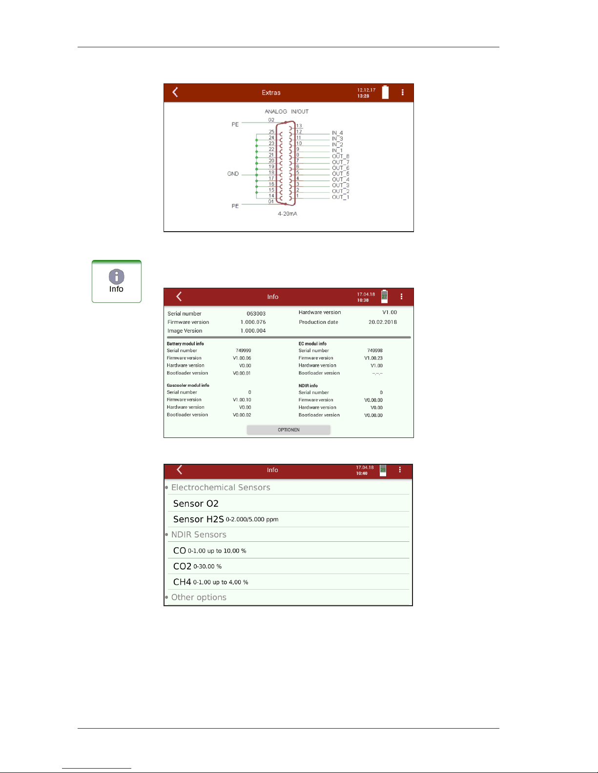
9.4 Analog output setup (4 – 20 mA) ............................................................................................. 28
9.4.1 Setting of lower limit (4 mA): ............................................................................................ 29
9.4.2 Setting of upper limit (20 mA): ........................................................................................ 29
9.4.3 Setting analog outputs during zeroing ........................................................................ 29
9.4.4 Pin assignment of the 4-20 mA interface ..................................................................... 30
9.5 Info ...................................................................................................................................................... 30
9.6 Options .............................................................................................................................................. 30
10 Information on the instrument components ....................................................................... 31
10.1 Firmware update ............................................................................................................................ 31
11 Specications ............................................................................................................................. 32
11.1 NDIR measured values ................................................................................................................. 32
11.2 Technical data ................................................................................................................................. 32
11.4 Gas sampling and conditioning ............................................................................................... 33
11.4.1 Electrochemical-, temperature- and pressure sensors ........................................... 33
11.5 Calculated values ........................................................................................................................... 34
11.5.1 Data communication........................................................................................................... 34
11.5.2 Analysis and calculations ................................................................................................... 34
11.6 Fuel types .......................................................................................................................................... 35
12 Appendix ..................................................................................................................................... 36
12.1 Error diagnosis regarding the measuring instrument ...................................................... 36
12.2 Insert a static IP-address .............................................................................................................. 37
12.2.1 Settings for the software MRU4win ............................................................................... 39
12.3 Spare parts ....................................................................................................................................... 41
13 Declaration of conformity ........................................................................................................ 42
Page 5

MRU
5 / 44
MGA
prime
Version 1
Introduction
1 Introduction
y This manual enables you to understand and safely operate this MRU
Analyzer MGAprime.
y Please read this manual with great vigilant and get familiar with the
product before using it.
y This analyzer may only be operated by competent personnel and for its
intended use.
y Please pay special attention to all safety directions and warnings to
prevent personal injuries and damaging of the product.
y We can’t be held responsible for any injuries and/or damages that oc-
cur by not following the instructions in this manual.
y Always keep the manual near you when working with the analyzer, to
be able to read instructions as needed.
Please ensure to hand over all documents to when handing the analyzer over to others.
1.1 Intended use
The Analyzer MGAprime is designed for the gas analysis of ue gases,
as they are emitted from gas/oil burners, engines, or heating and power
appliances.
The instrument is intended to support the user in control and indicative
measurements in an ecient, accurate and reliable way
The analyzer is specically not intended as a safety device or personal
protective equipment; it should not be used as a warning device to warn
people against the presence of harmful gases.
The instrument was manufactured according relevant normatives and
regulations. It has to used within it’s intended use.
The Instrument must not be modied from the design or safety engineering.
Modications of any kind by the user will render the declaration of
conformity.
Syntax
Please note that this manual makes use of the scientic notation of gases
(NO2), while the instrument itself and it’s screen shots display the gases in
upper case letter only, i.e. (NO2).
This instrument meets the requirements of the valid
European and national regulations.
You can ind the declaration of conformity in the appendix.
Page 6
MRU
6 / 44
MGA
prime
Version 1
Introduction
1.2 About us
The Analyzer is produced by the MRU GmbH in Neckarsulm, Germany
(founded in 1984), a medium sized company that specializes in developing, producing and marketing high quality emission monitoring analyzers. MRU GmbH produces a wide range of instruments, from standard
analyzers up to tailor made industrial analyzers.
Plant 1: Sales, Service, R&D
Plant 2: Production
MRU GmbH
Fuchshalde 8 + 12
74172 Neckarsulm - Obereisesheim
GERMANY
Fon +49 71 32 99 62 0 (Zentrale)
Fon +49 71 32 99 62 61 (Kundendienst)
Fax +49 71 32 99 62 20
Email: [email protected]
Internet: www.mru.eu
Page 7
MRU
7 / 44
MGA
prime
Version 1
Information for product and safety
2 Information for product and safety
2.1 Safety manual
All general information and safety precautions of MRU products are listed
in the supplied separate safety manual.
Therefore this manual must be read and observed before the rst use of
the instrument.
Instrument-specic safety and warning requirements in this manual are
prexed before dangerous actions.
2.2 Safety precautions
The used category’s of safety precautions are here explained once more.
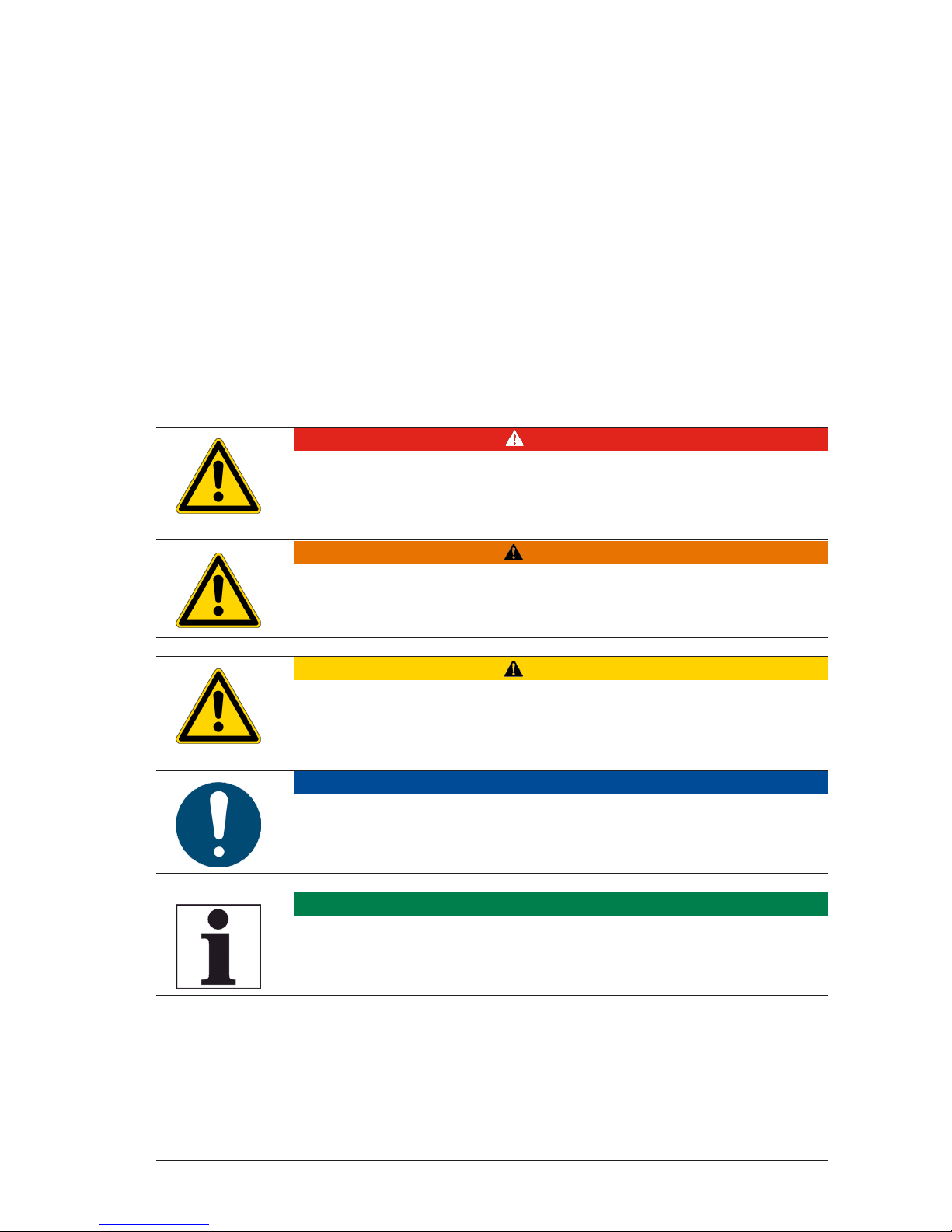
Identies an immediate, impending hazard that, if ignored, will result in
severe bodily injuries or death.
DANGER
Identies an immediate, impending hazard that, if ignored, may result in
severe bodily injuries, material damage or death.
WARNING
Identies a possibly dangerous situation that, if ignored, may result in
minor injuries.
CAUTION
ATTENTION
Identies a possibly harmful situation that, if ignored, may result in damages to the device or its surroundings.
NOTE
Identies user tips and other especially important information.
Page 8

MRU
8 / 44
MGA
prime
Version 1
Description
3 Description
3.1 Task
The instrument is designed for the gas analysis of ue gases, as they are
emitted from gas/oil burners, engines, or heating and power appliances.
The instrument is intended to support the user in control and indicative
measurements in an ecient, accurate and reliable way
The instrument provides a full set of all equipment and sensors required
for a emission control measurement:
y heated probe incl heated lter
y heated sample line
y gas conditioning unit including lters and gas cooler
y gas pump and ow control
y gas sensors
Available accessories include sensors for temperature or ow measurement.
The user interface allows for a modern and intuitive way to operate the
instrument. Running a commercial LINUX operating system, it allows as
well for lot of options for data transfer and storage.
For an overview on all available options please refer to the company’s
home page or sales representatives.
3.2 Gas ow diagram
The analyzer draws a sample of the ue gases from the duct using a builtin gas pump through the probe is cleaned and dried using a gas cooler
and built-in lter and analyses the extracted gas with electrochemical
and NDIR sensors.
Draft and temperature are measured at the tip of the sampling probe.
A
B
C
D
E
F
2 3 5 2 6 7
11 9 24810
1
Page 9
MRU
9 / 44
MGA
prime
Version 1
Description
A Fresh air inlet B Sample gas inlet
C Condensate outlet D Di. Pressure connector
E Vent collection box F Vent outlet
1 Sample gas lter (PTFE) 2 Dust lter
3 Auto-zero solenoid valve 4 Sample gas pump
5 Double stage gas cooler 6 Sample ow sensor
7
Oxygen sensor
O2-ECS or O2 paramagnetic
8 Vent pump
9 Infrared (NDIR) bank 10 Acrodisc PTFE lter
11 Di. pressure sensor
3.3 The measuring instrument
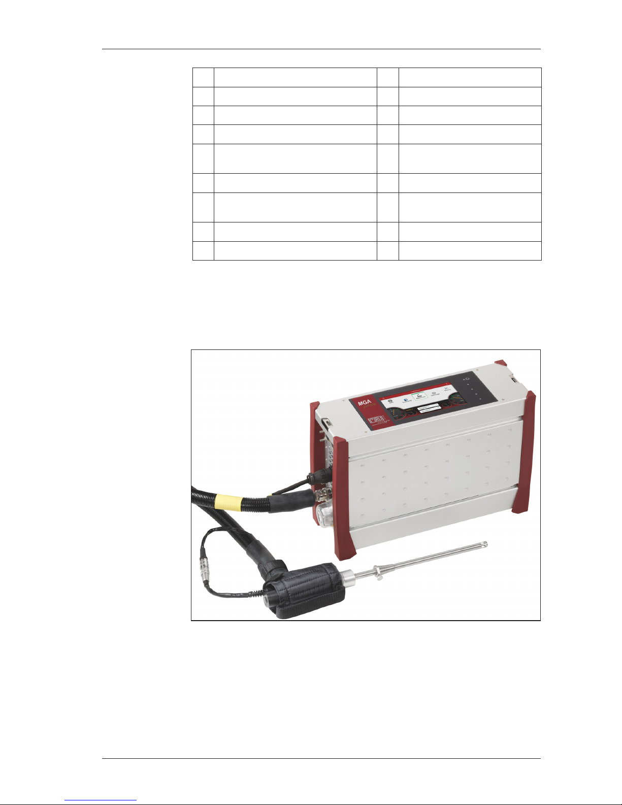
The measuring instrument consists of a compact and robust metal housing with shock-absorbing rubber corners. All electrical and pneumatic
connections are located on the both front sides of the instrument. It is
operated exclusively via the touch-sensitive touch screen.
Page 10
MRU
10 / 44
MGA
prime
Version 1
Description
3.4 Connectors
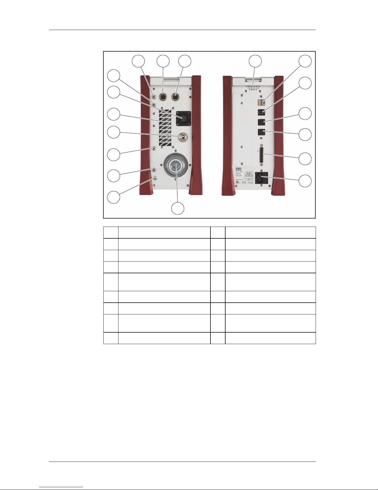
1 Loudspeaker 2 Ethernet (LAN)
3 USB socket 4 Second USB socket (Option)
5 RS485 (Option) 6 Analog outputs 4 ... 20 mA
7 Mains power supply 8 Sample gas lter
9
Condensate outlet port
Hose connection DN 4/6
10
Sample gas outlet port (VENT)
Hose connection DN 4/6
11 Fresh air inlet port 12 Sample gas inlet port
13 Outlet fan of gas cooler 14 Outlet fan of gas cooler
15 Pressure-/di. pressure 16
Pressure-/di. pressure
(Absolute pressure)
17 Combustion air temperature 18 AUX socket
3.5 Probes
The Analyzer is available with dierent probes, both with xed and exchangeable probe tubes.
y for high and less dust content
y for fuel temperatures up to 800 °C (stainless-steel probe tube),
y for fuel temperatures up to 1.200 °C (Inconel steel probe tube),
y for fuel temperatures up to 1.700 °C (ceramic probe tube)
y with and without heated pre-lter
y with and without heated gas sampling line
y probe tubes in dierent lengths, from 300mm to 2000mm
A complete list of available probes can be found in the current price list
of this analyzer.
16 1 2
4
5
6
8
9
10
11
12
13
15
14
7
17 18
3
Page 11

MRU
11 / 44
MGA
prime
Version 1
Description
3.6 Gas sampling probe “TR”
Heated probe with heated and exchangeable glass lter. The probe
tube includes a gas temperature sensor and is available in dierent
tube lenghts.
1 Probe handle 2 Probe tube
3 Fast locking coupling 4 Probe cone
5 Cable plug (14-pin) 6 Heated hose line
7 Cable coupler (5-pin) 8 Fast locking coupling
9 Filter lock
3.7 Gas conditioning
The sucked sample gas is dried and ltered before it is fed to the sensors.
A double stage sample gas cooler with Peltier element is used for drying. The condensate liquid appearing in the gas cooler is pumped to the
condensate outlet by means of a peristaltic pump. The condensate forms
drops at the outlet of the instrument.
Optionally, connect a hose (DN 4/6) to the condensate drain.
The VENT output delivers the sample gas after the analysis stage. If
For subsequent ltering, a round lter is used on the front of the measuring instrument.
1
5
6
7
8
9
2 3 4
Page 12

MRU
12 / 44
MGA
prime
Version 1
Description
3.8 IR measurement
The instruments NDIR gas sensor is able to detect up to 8 dierent gases.
It is most advanced in terms of its long-term stability due to a dedicated
stabilization technology including a permanent zeroing by operating the
bench at two dierent gas pressure values.
Due to its low noise and being drift free, it is perfectly suited to longterm measurements.
Principle of the IR-bench (NDIR)
1 IR source 2 Gas entry
3 Sample gas cell 4 Gas exit
5 Band pass lter 6 IR detector
An infrared source delivers IR radiation in the wavelength range between
1 and 10 um, which is relevant for the absorption of gas components to
be measured.
The target gas absorbs a portion of the IR radiation, which is detected by
a wavelength selective detectors and the end of the sample gas cell.
The absorption value is correlated with the gas concentration, while all
eects of cross sensitivity to other gases are corrected by an internal
software algorithm.
As the IR bench is operated successively at two dierent gas pressure
values, it is possible to eliminate all drift eects, which would otherwise
contribute to the absorption signal.
21 3 4 5 6
Page 13

MRU
13 / 44
MGA
prime
Version 1
Operation
4 Operation
4.1 Commissioning
The instrument is delivered as a complete assembly ready for use.
f Check the instrument regarding condition and integrity after delivery.
f Connect the instrument to the power grid.
Ö The instrument switches on and start the operating system.
Ö Blue LEDs for ON and power supply are switched on.
Ö The instrument runs a start procedure which includes:
y self test
y warm-up of the NDIR bench
y cool down the double stage gas cooler, indicated by the symbol
y Zeroing, indicated by symbol
f Charge battery for more than 8h is recommended after rst start to
allow the battery to charge completely. Operation of heated probe and
sample line is only supported when connected to power grid.
Ö The battery is charged as soon as teh connection to power grid is
established.
Ö The blue LED will be blinking slowly.
Heating of probe and probe tube are unsupported in battery mode.
4.2 Switch on
f Touch the
⏻
button for 3 sec. minimum
Ö LED lights blue
f Release the ⏻ button
Ö LED lights red, analyzer runs up
4.3 Switch o / Reset
4.3.1 Switch o
f Touch the “Context menu” on the display
f “Turn instrument o”
Ö Do you wish to turn instrument o?
f “YES”
Ö “The system will shut down”
or
f Touch the
⏻
button
Ö Do you wish to turn instrument o?
Ö “YES”
Ö “The system will shut down”
4.3.2 Reset
f Touch the ⏻ button during ashing LED for 30 sec. minimum
f After change to continuous lighting, release the ⏻ button
Ö The instrument will switching o with reset
Page 14
MRU
14 / 44
MGA
prime
Version 1
Operation
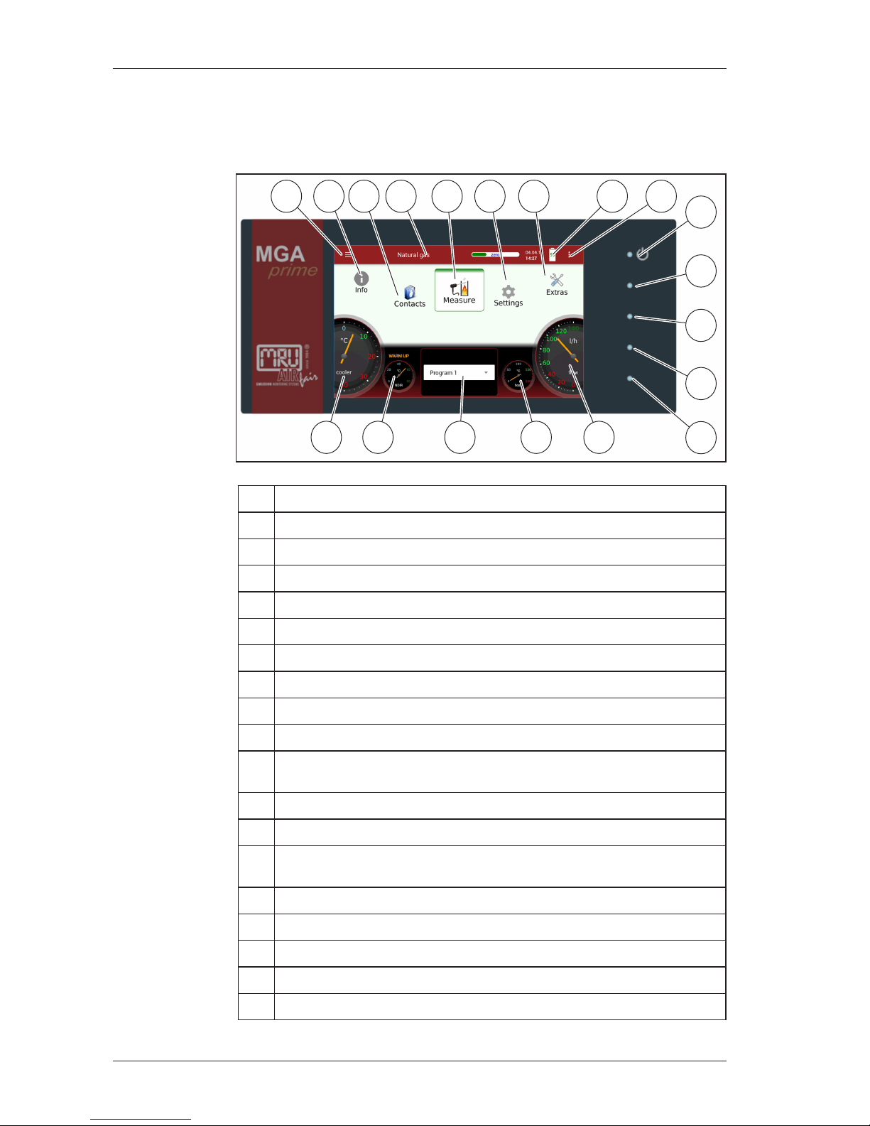
4.4 Operating panel
All functions are controlled via the touch surface of the instrument. Different gestures are available in the individual menus and windows.
1 Power-on and reset
2 Reserve
3 Reserve
4 LED display mains operation/battery charging mode
5 Reserve
6 Current ow rate
7 Current temperatures heated hose
8 Selected measuring program, e.g. Test or measurement program
9 Current temperatures of NDIR bench
10 Current temperatures of gas cooler
11
Access to detailed information on the instrument components.
Especially for service or inquiry
12 Menu info
13 Menu contacts
14
Status bar: display of zero point, alarms, executed measuring program, selected fuel, heat-up-, cool-down phase
15 Menu measure
16 Menu settings
17 Menu extras
18 Battery Charge indicator
19 Context menu with window-dependent additional functions
1
2
4
5
7
1915
8910 6
1412 1311 18
3
16 17
Page 15
MRU
15 / 44
MGA
prime
Version 1
Settings
5 Settings
After the analyzer has been inspected and is ready for start-up it can be
switched on and personalized settings can be entered. These settings can
be changed at any time.
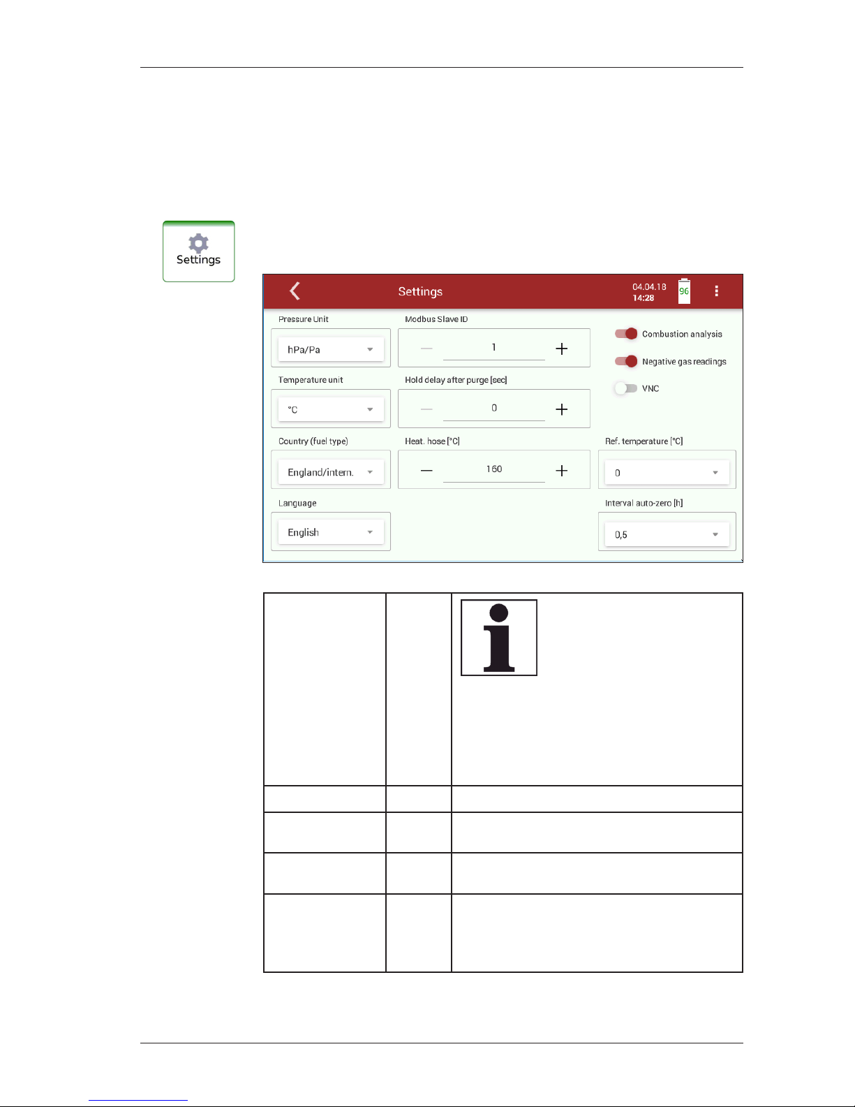
5.1 Analyzer settings
After the analyzer has been inspected and is ready for start-up it can be
switched on and personalized settings can be entered. These settings can
be changed at any time.:
Country Option By changing the country the
O2 reference values settings
are lost. The fuel list is reset.
Similarly, country-specic
defaults and methods of
measurement are selected as a result.
Ensure the correct setting of the country
in which you are performing the measurement to ensure that all relevant ones are
set up
Language Option Select instrument languages
Modbus slave Modbus address of the instrument for the
remote control via Modbus
Temperature
heating hose
130°C +180 °C
Combustion
analysis
on/o
Setting combustion analysis to ON
allows for several calculation performed
by the instrument, which are fuel type
dependent, e.g. Lambda, heat loss.
Page 16
MRU
16 / 44
MGA
prime
Version 1
Settings
Negative gas
readings
on/o Negative gas readings Caused by tem-
perature drift of a sensor are suppressed
(shown as zero) or displayed
VNC on/o VNC Viewer for remote control via LAN
Reference temperature
Calculation of the values for a standard
state at reference temperature
Interval
auto-zero
Interval time after which the instrument
performs a zero-point
5.2 Setting time and date
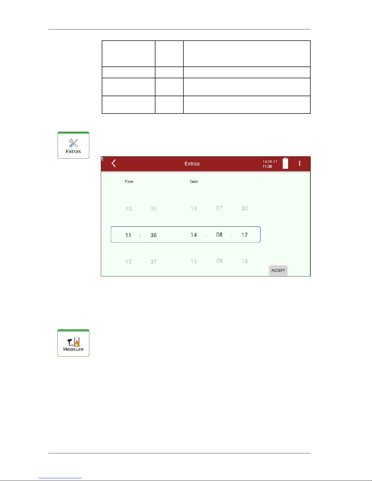
In the Extras menu, you can check the date and time and, if necessary, set
it. When connected to the Internet, the time automatically synchronizes
itself.
f The time and date can be set in the middle black number series by
pushing up and down the gray number row.
f Accept the changes with ACCEPT.
5.3 Conguration of measurement program
The Analyzer provides in the Measure menu various measurement
programs, which can be selected in the main window. Each measuring
program denes the properties of the measuring window:
y Measurement program
The measured value window can be freely set with regard to the displayed measured values, of the underlying fuel. The purge limit of the CO
sensor (if available) can be set
y Test program
The measured value window shows predened values and cannot be
changed. Can be used in instrument testing to obtain standardized displays, e.g. can easily be checked with test gases.
y If so, further measuring programs
Page 17
MRU
17 / 44
MGA
prime
Version 1
Settings
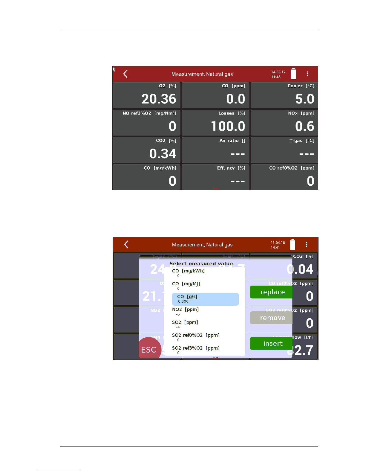
The measurement window for gas analysis can be congured and adapted to your needs. The measuring window initially displays 12 measured
values, by a scrolling gesture it will display more values.
Moving a value eld
f Touch and hold the value eld.
Ö Value eld will be framed.
f Move the value eld to a dierent position.
Ö The other value elds move automatically.
Assign a measured value
f Double touch the value eld.
Ö A list with of all available measured values is displayed.
f Choose the wanted value and “replace”.
Page 18
MRU
18 / 44
MGA
prime
Version 1
Settings
5.4 Gas ow measurement
Set up measurement window
With the ow measurement option are further measurements available:
y v-ow
y Flow rate
y Mass ow carbon
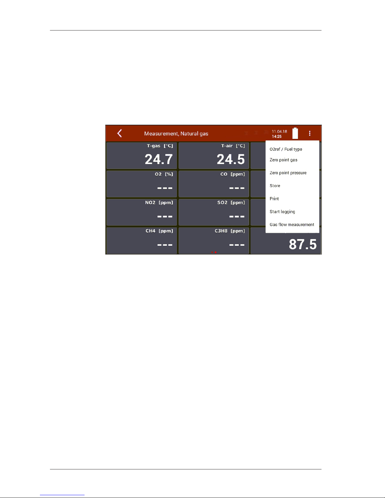
Parameter for gas ow measurement
f Choose the right context button - menu item “gas ow measurement”.
Page 19
MRU
19 / 44
MGA
prime
Version 1
Measurement
6 Measurement
6.1 Preparation of each measurement
6.1.1 Power supply
The analyzer can be operated with an internal battery to warm up the
instrument or to use internal instrument functions. A mains connection
is required
for the measurement including heated gas sampling probe and
heating hose.
6.1.2 Charging state of the battery
The battery symbol in the display indicates approximately the remaining
capacity of the battery.
From 2% remaining capacity, the charging indicator starts to ash red. If
the instrument is not connected to the mains power supply within one
minute, the analyzer switches o to prevent battery discharge.
Even when the battery is discharged, the instrument can be operated
completely on the power supply.
6.1.3 Connections to the instrument
f Connect the gas sampling probe to the instrument (gas plug and elec-
trical plug).
f Consider to connect a hose or collecting container if necessary to the
condensate outlet when appropriate.
f The hose and any connected reservoir connected to the outlet must
not be closed against ambient or include an air outlet to avoid overpressure.
f Please note that measuring gas may leak at the instrument side or at
the VENT outlet. Connect a pump to the VENT output to collect the
sample gas. If an “active VENT” option is installed, an internal gas pump
feeds the sample gas completely to the VENT outlet, where an evacuating gas hose should be connected.
f In the case the option active vent is installed, note that the sample gas
at the exit may be diluted with ambient air and is therefore not adequate to be reused in the process.
f Ensure that ambient fresh air can be sucked in at the fresh air inlet.
Consider to connect a hose leading to fresh ambient air, when the
instrument’s environment contains toxic gases or a high CO2 level.
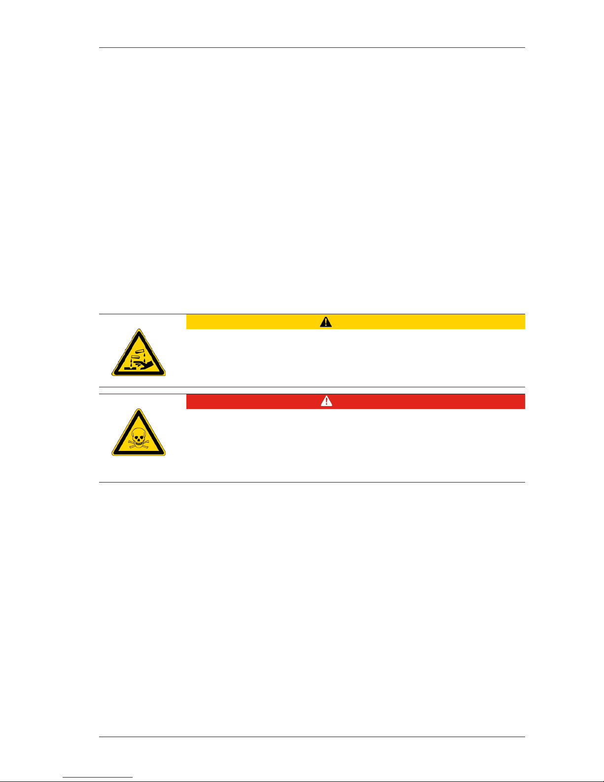
Acid from the condensate
Acid burns may result from weakly acidic liquids from the condensate.
f If you come into contact with acid, wash the area immediately using a
lot of water.
CAUTION
Risk due to toxic gases
There is a risk of poisoning.
Noxious gases are sucked in by the measuring device and released into
the ambient air.
f Only use the measuring device in well ventilated spaces.
DANGER
Page 20
MRU
20 / 44
MGA
prime
Version 1
Measurement
f The ow rate of the gas should be within the specied range. Other-
wise, please check probe and lter for clogging
f Temperatures of NDIR and heating hose should be within the specied
range in order to guarantee a sucient measuring accuracy.
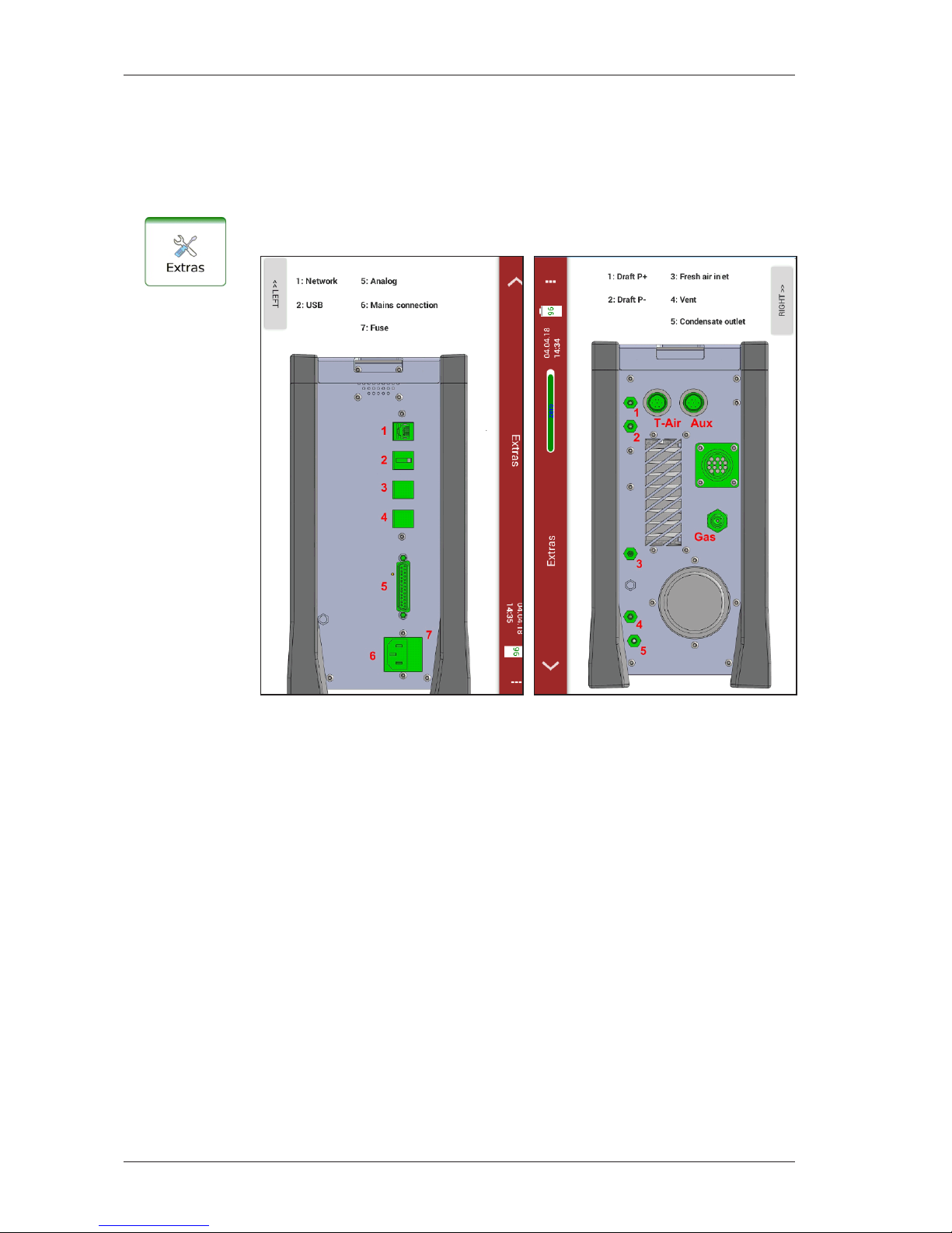
In the Extras menu under “Connections” the connection drawings are
displayed:
6.1.4 Operating temperature
The internal gas cooler operates at 5°C, which is the dew point of the
sample gas to the sensors. Components along the gas line may be damaged if they are colder than 5°C and condensation appears internally.
Therefore, if the Analyzer has been stored very cold below 0°C, it is essential to wait for the Analyzer to warm up in a warm environment in order
to avoid such condensation! In such cases, take a typical warm-up time
for the instrument of one hour into account, especially when wet ue
gases are to be measured.
If the operating temperature is not within the permissible range, a corresponding message is displayed.
6.1.5 Filter
The probe lter and the round lter must be checked before and after
each measurement
6.1.6 Switch-on, warm-up phase, zero point
After switching on, the instrument can always be operated, even if no gas
analysis can take place during the warm-up phase. The instrument independently performs the following actions during the warm-up phase:
Page 21
MRU
21 / 44
MGA
prime
Version 1
Measurement
y Heating the probe and the heating hose
y Warm up the NDIR bench (if available)
y After the operating temperatures have been reached, the gas pump is
switched on and the analyzer takes the zero point with fresh air.
y After the zeroing, the analyzer is ready for operation
If a new zero point is required by further heating the instrument, it can be
started via the context menu.
6.1.7 Instrument leak test
f Check all connections for correct t.
f Check all hoses and hose connections (from the tip of the probe to the
gas inlet of the measuring instrument) for leaks.
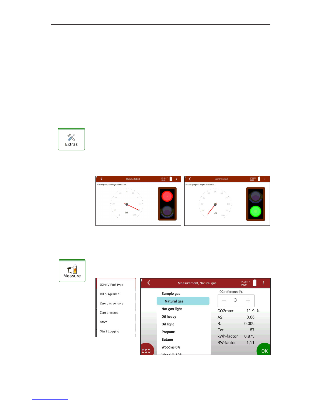
The Analyzer has a built-in “leak test” in menu Extras for checking the
tightness of the gas paths. This is done by measuring the remaining gas
ow when the gas path is closed.
f Seal the sample gas inlet
f If the complete gas path is to be tested for leakage - at the probe tip.
If the system is tight, the trac light is green and the l / h pointer points
to 0.
6.2 How to take a Measurement
6.2.1 Fuel type selection and O2 reference
The fuel selection can be selected in the menu Measure with the O2
reference / fuel in the “context menu”.
For this, the combustion analysis have to be switched on, also see 5.1
Page 22
MRU
22 / 44
MGA
prime
Version 1
Measurement
6.2.2 Store the measurement results
The measured values can be stored in a site via the context menu / Store
menu entry.
The measurement itself continues until switch o of the analyzer.
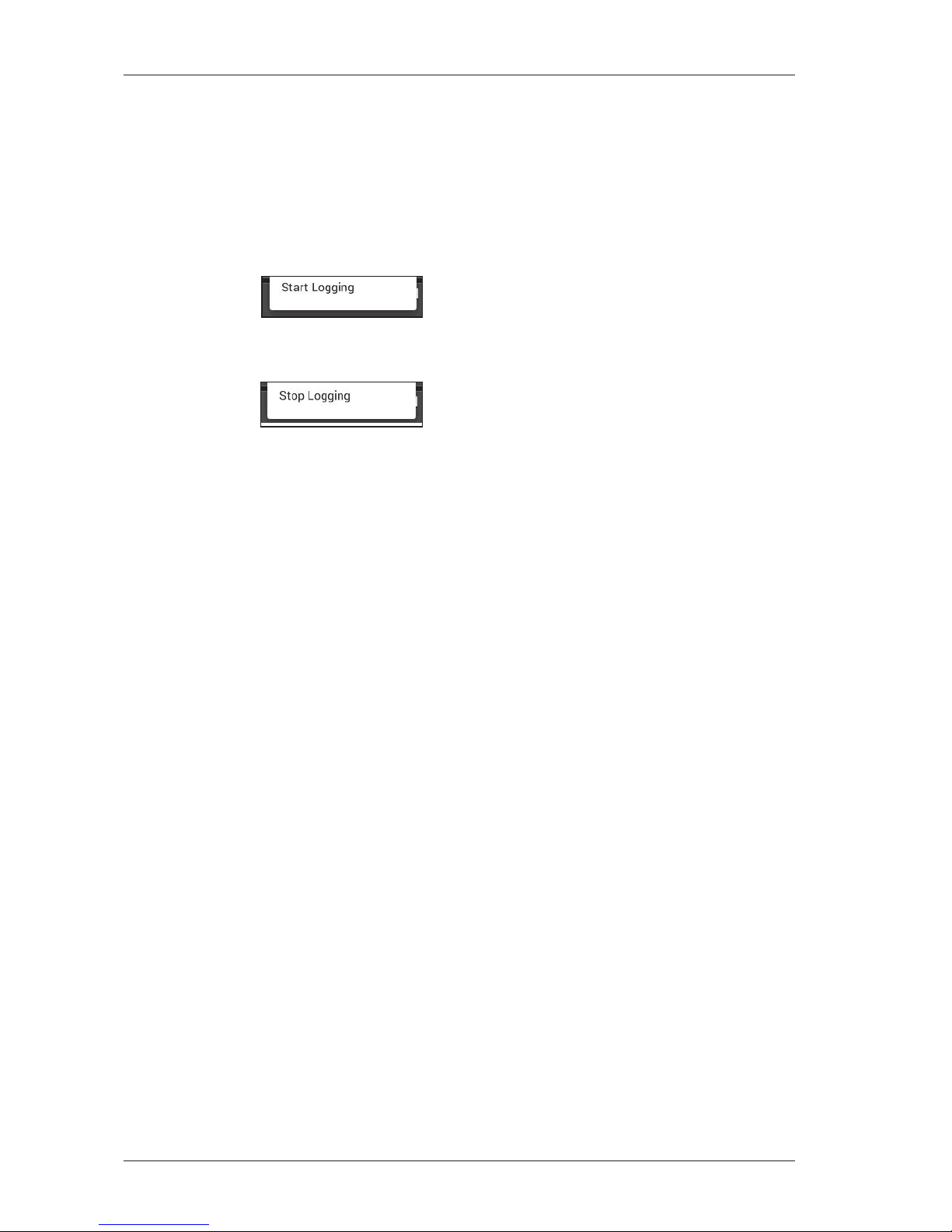
Continuous data logging
A continuous measurement logging is possible via the context menu /
“Start logging”.
With “Start Logging”, the currently measured values are stored in a site
every 10 seconds.
End the data logging with “Stop logging”.
Page 23
MRU
23 / 44
MGA
prime
Version 1
Maintenance and cleaning
7 Maintenance and cleaning
7.1 Cleaning and maintenance
The Analyzer needs only low maintenance eort for long value preservation
After every measurement:
f Remove the gas sampling tube from the analyzer, so that the hose can
dry.
Occasionally:
f Cleaning of the probe and the probe tube.
f after longer disuse load battery rst and afterwards approx. all 4 weeks.
f Check the lter in the probe head (if available), replace if necessary.
f Check the round lter at the front of the instrument and replace if
necessary.
Maintenance
An annual service check and if necessary adjustment of the sensors at an
MRU service department (www.mru.eu) are recommended for the pres-
ervation of value.
Acid from the condensate
Acid burns may result from weakly acidic liquids from the condensate.
f If you come into contact with acid, wash the area immediately using a
lot of water.
CAUTION
Page 24
MRU
24 / 44
MGA
prime
Version 1
Data memory
8 Data memory
8.1 Organization of the Data memory
Basis of the data memory of the analyzer is a set of sites stored in the
instrument. Every site exists of a unique site number and 12 freely usable
text lines which can have, e.g., the address, customer name etc.
The instrument can store up to 1.000 dierent sites.
Sites can be created in the instrument and be changed. Measurements
are stored by assigning them to a site. Measurements can be, on this
occasion, singles ue gas measurements or other measuring programs
available in the instrument.
8.2 Information about the data memory
In the menu Contacts, item “storage” you select “memory info “to get
information about the actual memory volume. The part of free memory,
the total number of the stored sites and the number of the measurements stored all together, split in the kind of the measurement is listed.
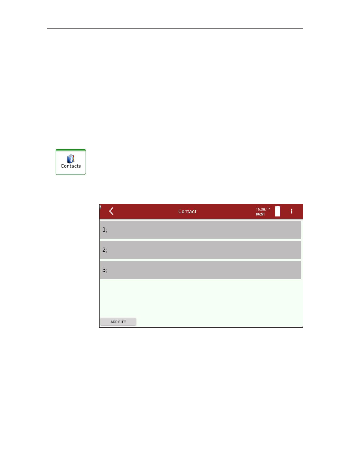
8.3 Site administration
Available sites are listed in this menu
The “ADD SITE” button creates a new site number. Further changes may
be introduced after selecting a specic line.
Page 25
MRU
25 / 44
MGA
prime
Version 1
Data memory
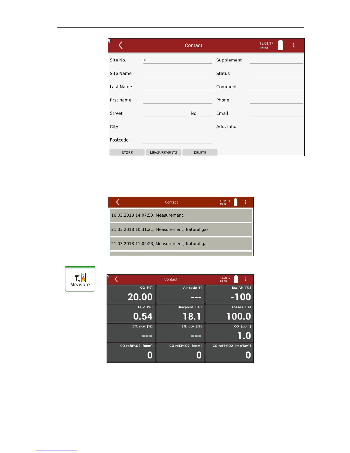
y Changes in the site description may be entered and stored
y A site may be deleted by the “delete” button.
y Measurements assigned to the selected site are displayed when the
“Measurement” button is activated.
In the menu Measure you can see stored measurements
Page 26
MRU
26 / 44
MGA
prime
Version 1
Data memory
8.4 Data transfer via USB (CSV export)
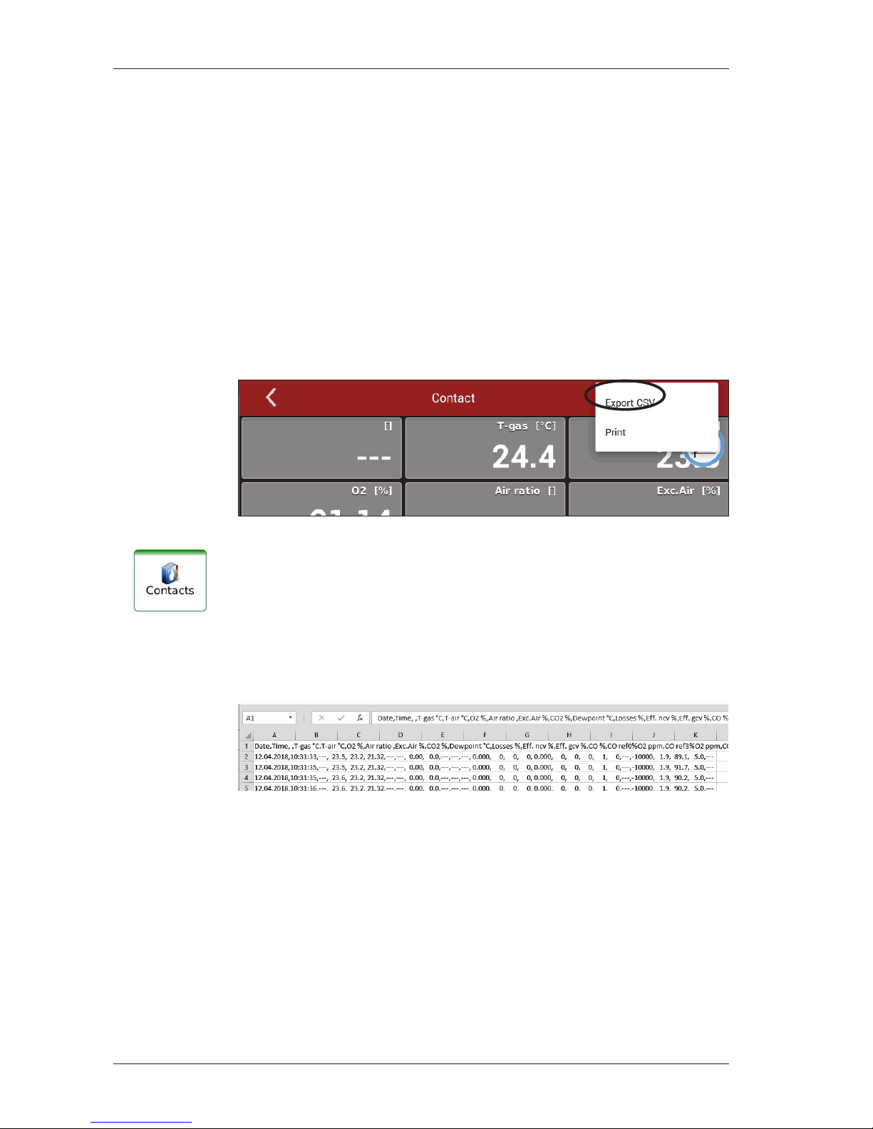
The data exchange format is CSV. A character-separated values (CSV) le
is a simple text format for a database table. Each record in the table is
one line of the text le. Each eld value of a record is separated from the
next by a character. The analyzer uses a semi-colon ‘;’ as value separator
(other implementations use sometimes a comma). CSV is a simple le
format that is widely supported, so it is often used to move tabular data
between dierent computer programs, for example Microsoft Excel™ or
Access™, that support the format. Also other computer programs oer
this type of interface because it is widely spread and easy to use.
The following functions are available
y Export of sites
y Export of ue gas measurements
f Insert USB Stick
f Select “site” and “measurement” in Contacts menu
f Now press “EXPORT CSV”
After this… you nd in the USB stick directory “1113Export” the export
les.
The le name is such as those “09_04_2018_15_02_02__Measurement__
Natural_gas.csv”….
f Open this le (*.csv) with Excel…. (don’t use the dat les… don’t use
“Internal log settings” are only for internal use or diagnostics)
8.5 Export of measurements
This function is used to export the measurements from the analyzer to a
computer program.
Attention, This function is not suitable for back-up or for the transfer to
another analyzer because the exported le cannot be imported again!
The created le has the name ‚EMIxxxxx.csv’, in which the xxxxx are continuing 5 digit numbers with leading zeros.
The created le has a column header with the following information: Site
number, Date/Time,
Measuring program name, Fuel type, CO2max, O2reference, and all measured values that the analyzer can measure.
Page 27
MRU
27 / 44
MGA
prime
Version 1
Extras
9 Extras
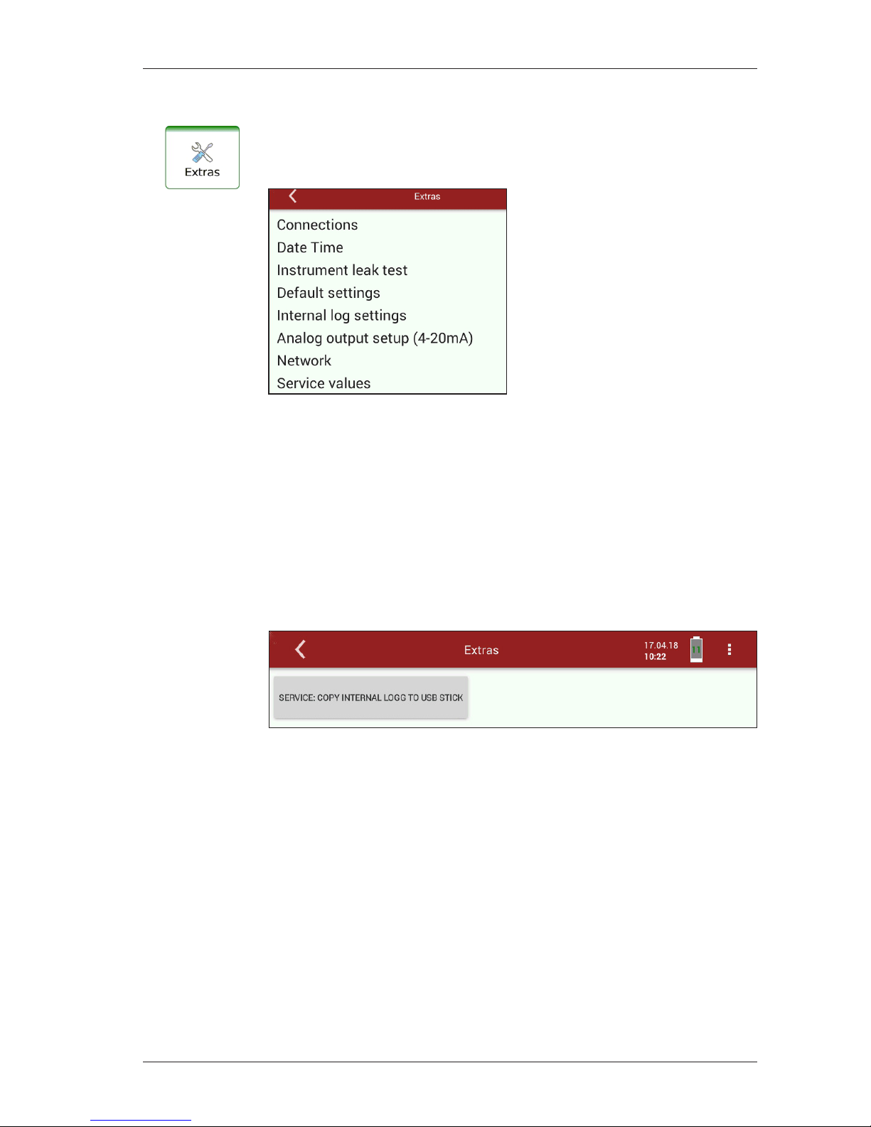
IIn the Extras menu, the time / date setting (chapter 5.2) and the connection possibilities of the instrument (chapter 3.4) are further menu items
for service purposes available.
The rst menu items have already been explained during “settings”.
9.1 Access key
The entry of an access key (password) is for maintenance action and
allows experienced users to operate on the operating system level. Not
required for regular use.
9.2 Internal Log Settings
The analyzer stores internal parameters at regular intervals to allow for
an optimized support from experienced service sta. These les can be
copied to a connected USB stick and sent via email if required to do so.
f Copy internal log to USB stick.
Page 28
MRU
28 / 44
MGA
prime
Version 1
Extras
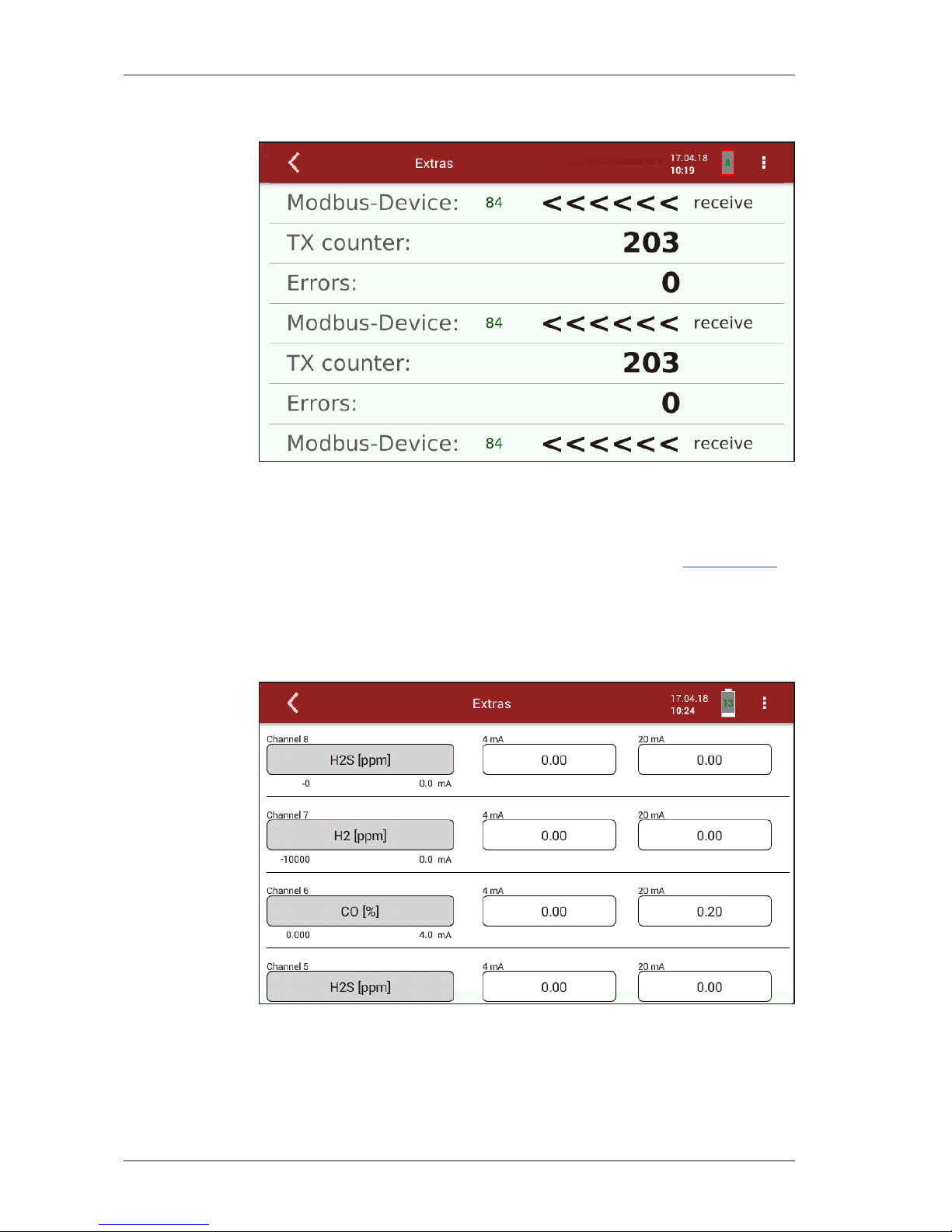
9.3 Service values
This screen displays a number of internal parameters and their values.
In case of unexpected behavior of the instrument it might be helpful to
communicate those values to our worldwide service sta: www.mru.eu
9.4 Analog output setup (4 – 20 mA)
There are 8 analog outputs available (4-20 mA).
Each analog output (channel) is assigned a measured variable and an
output range.
Page 29
MRU
29 / 44
MGA
prime
Version 1
Extras
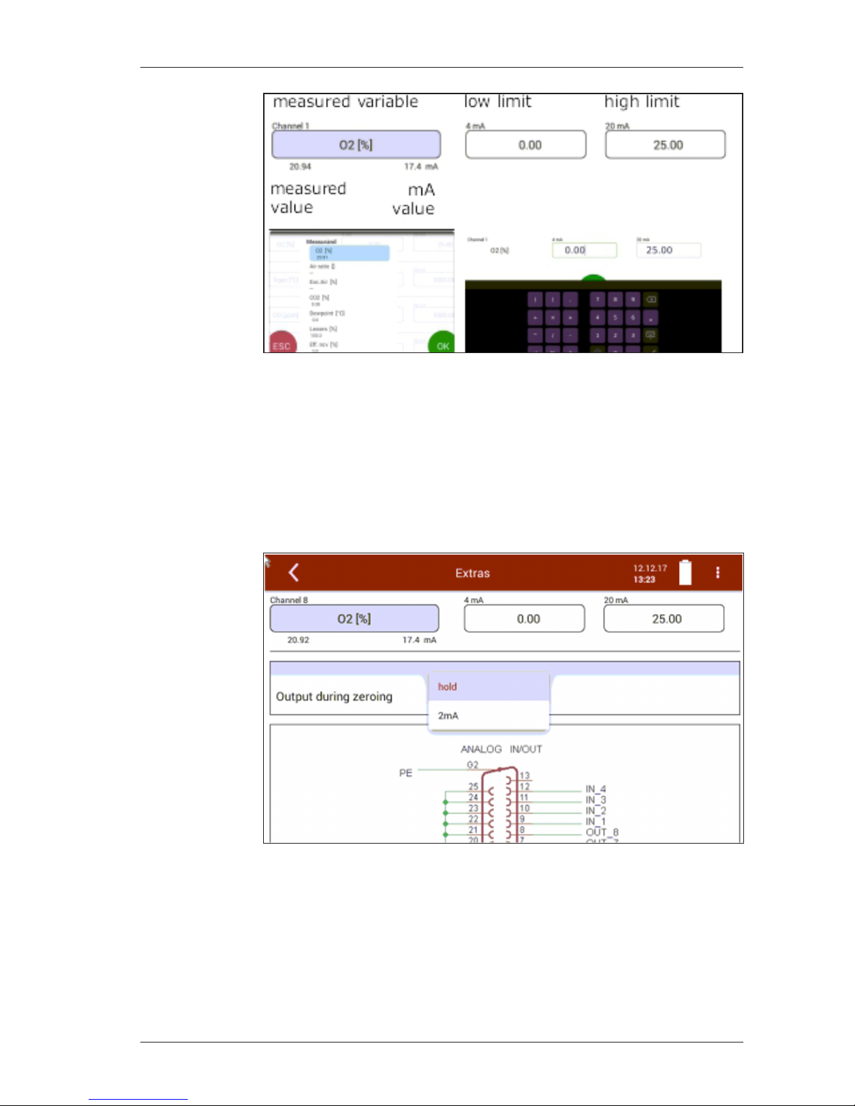
9.4.1 Setting of lower limit (4 mA):
This setting determines the lower end value, corresponding to 4 mA. If
the measured value falls below the set value, the analog output stops at
4 mA.
9.4.2 Setting of upper limit (20 mA):
This setting determines the upper end value, corresponding to 20 mA. If
the measured value rises above the set value, the value stops at 20 mA.
9.4.3 Setting analog outputs during zeroing
The following settings are possible
y Hold - The outputs kept the last values from before zeroing
y 2mA - The outputs change to 2 mA to indicate the zero point
Page 30
MRU
30 / 44
MGA
prime
Version 1
Extras
9.4.4 Pin assignment of the 4-20 mA interface
9.5 Info
In the Info menu, version information and installed options can be
viewed.
9.6 Options
Page 31
MRU
31 / 44
MGA
prime
Version 1
Information on the instrument components
10 Information on the instrument components
Especially for service or inquiry
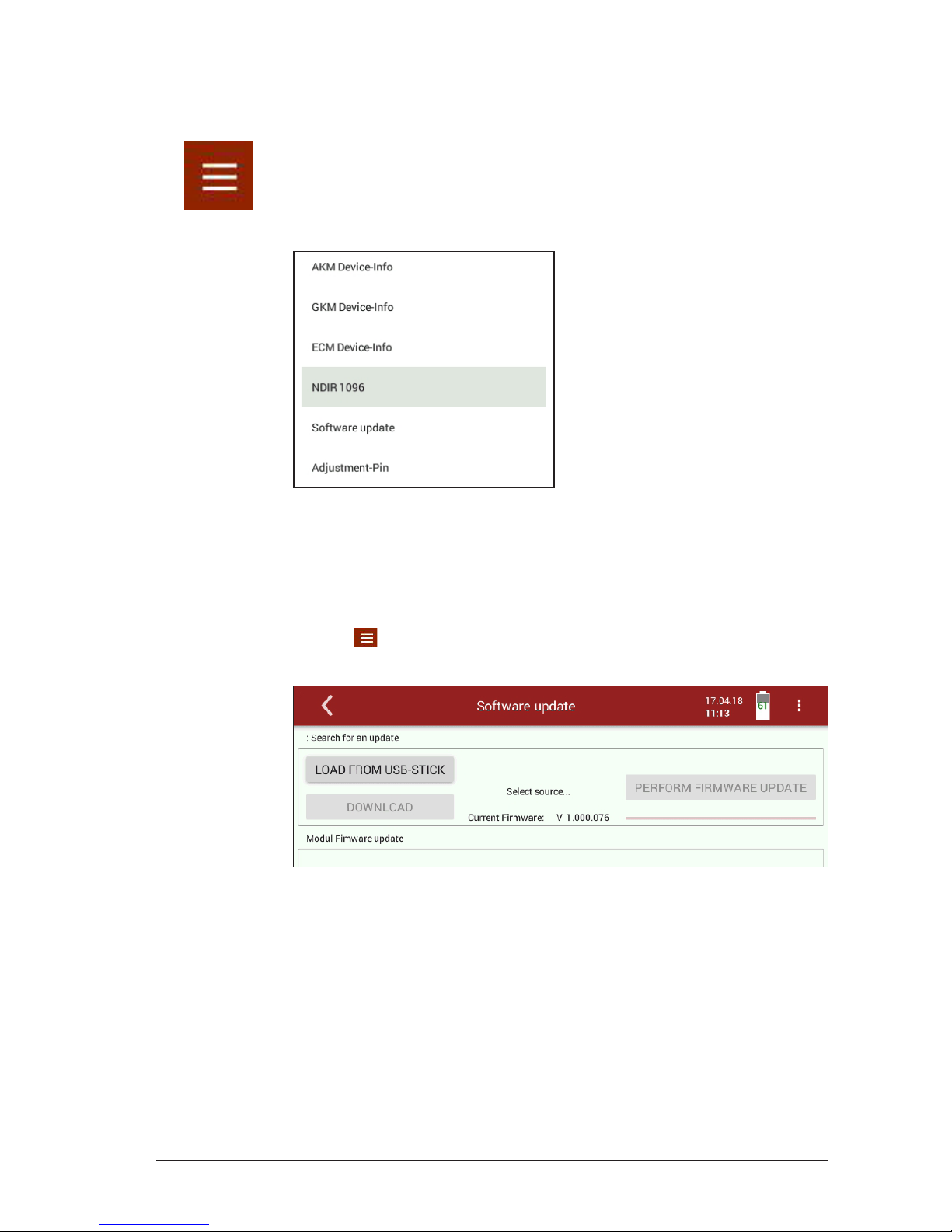
This menu can be selected from the main menu with the adjacent button.
In addition to special instrument information and the possibility of instrument matching for service stations, a rmware update is also possible.
10.1 Firmware update
Performing an update:
f Please extract the obtained le 1113Update.zip.
f Copy the unzipped le ‘1106.fwb’ to a USB stick in the root directory.
f Switch on the analyzer...
f Insert the prepared USB stick into a USB socket of the analyzer.
f Press
f Select the menu item “Software update”
f “Load from USB Stick”
f After copying to the analyzer press the button “Perform rmware up-
date”
Ö The rmware update starts
f After updating, turn the analyzer o
Ö After rebooting, the new rmware is installed.
Page 32
MRU
32 / 44
MGA
prime
Version 1
Specications
11 Specications
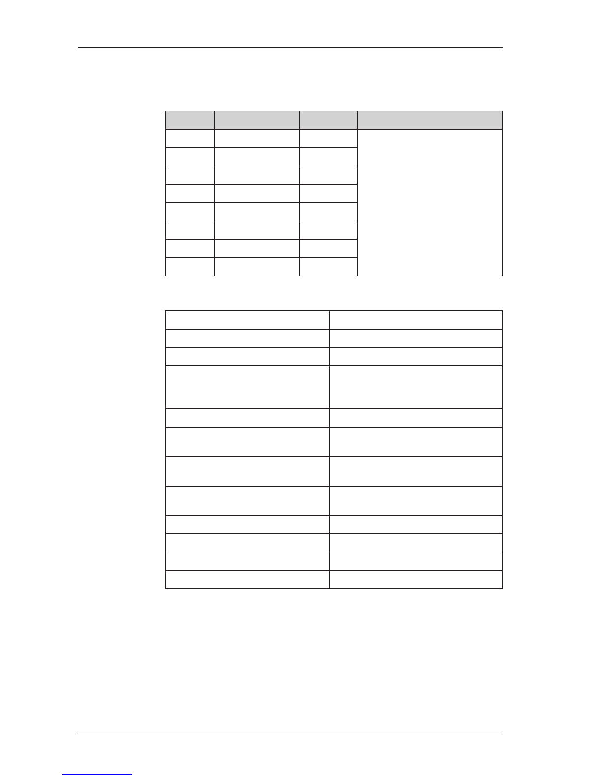
11.1 NDIR measured values
Gas Range Resolution Accuracy
NO 250 - 4000 ppm
1 ppm
Repeatability: 1% v.MB.
(CH4: 2% v. MB)
8h-Drift: 1% v.MB.
Linearity: 2% v. MB.
NO
2
200 - 1000 ppm
1 ppm
SO
2
200 - 4000 ppm
1 ppm
CO
2
40 Vol% 0,01 Vol%
CO 200 - 10000 ppm
1 ppm
N2O 200 - 1000 ppm
1 ppm
CH
4
500 - 10000 ppm
1 ppm
HC (C3H8) 200 - 10000 ppm
1 ppm
11.2 Technical data
Operating temperature +5°C - +45 °C
Rel. Humidity, non-condensing 90 %
Storage temperature -20 °C - +50 °C
Internal Battery Pack, capacity,
operating hours w/o gas cooler
and heated sample line
Li-Ion, 96 Wh, 6 h
Display 7” touch, < 750 cd/m2, 800*480 px
Power supply (w/o heated sample
line)
86 - 265 V / 47 - 63 Hz / 105 W
Weight instrument w/ 2 EC sensors.
7,5 kg
Weight instrument w/ 2 EC sensors plus case
16 kg
Size incl Case (WxHxD) 43 cm x 15 cm x 29 cm
Size incl Case (WxHxD) 51 cm x 29 cm x 51 cm
Housing Material Aluminium / TPU
IP degree of protection IP20
Page 33
MRU
33 / 44
MGA
prime
Version 1
Specications
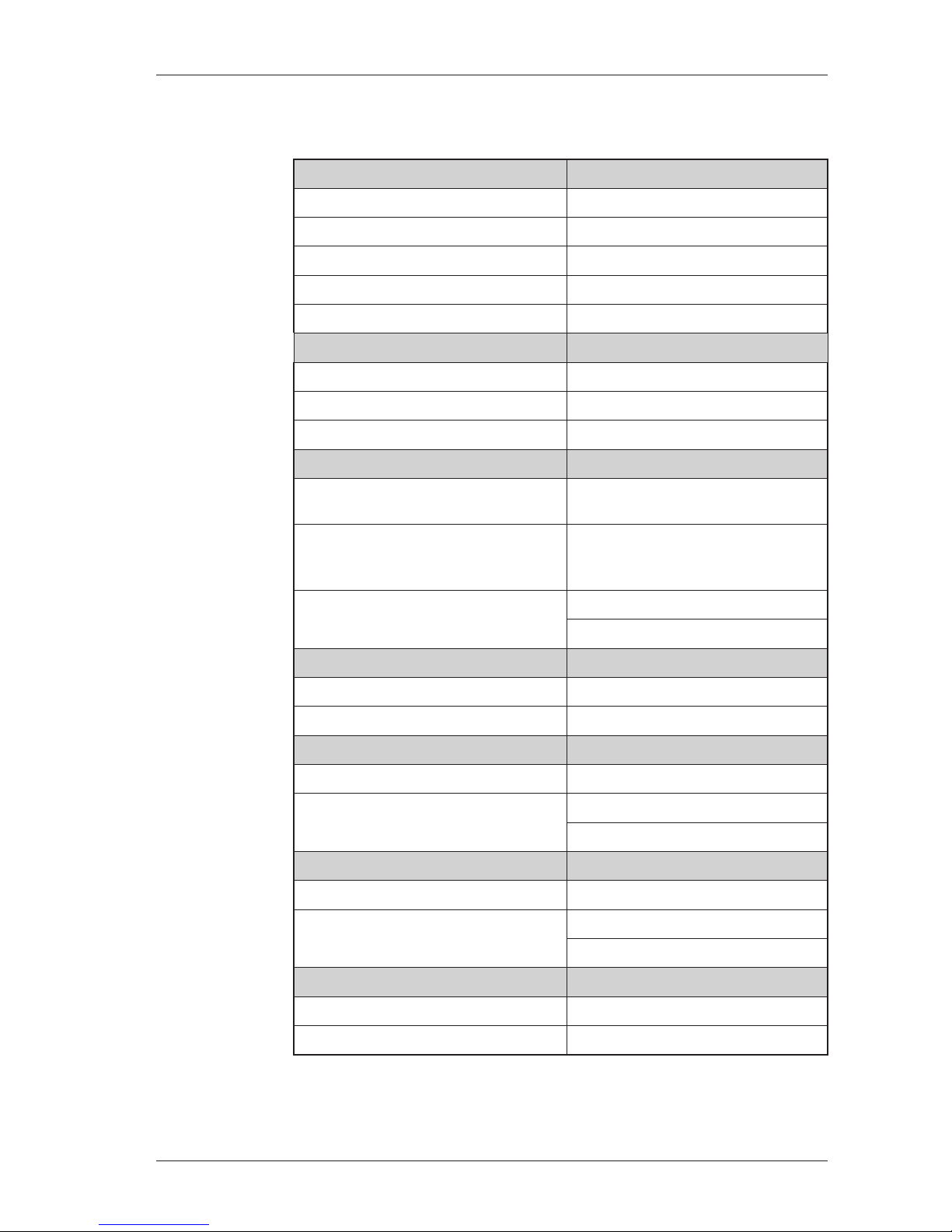
11.4 Gas sampling and conditioning
11.4.1 Electrochemical-, temperature- and pressure sensors
Electrochemical sensor O2 Long Life
Measuring range 0 - 25 Vol%
Resolution 0,01 Vol%
Abs. accuracy ± 0,2 Vol%
Response time T90 < 20s
Years expected lifetime (@air) 5 Jy
Paramagnetic sensor O2
Measuring range 0 - 25 Vol%
Resolution 0,01 Vol%
Accuracy 0,1 Vol%
Flue gas temperature TA
Measuring Range with high grade
steel probe pipe
0 - 800° C
Measuring range with Inconel probe
pipe
Short time only (up to 20 mins
0 - 1100° C
0 - 1350° C
Accuracy abs. / reading
±2° C /
1%
Air temperature Tl
Measuring range 0 - 100°C
Abs. accuracy 1 °C
Draft
Measuring range ± 120 hPa
Accuracy abs. / reading
0,02 hPa
1 %
Differential Pressure
Measuring range ± 120 hPa
Accuracy abs. / reading
0,02 hPa
1 %
Barometric Pressure P
abs
Measuring range 300 - 1200 hPa
Accuracy ± 3 hPa
Page 34
MRU
34 / 44
MGA
prime
Version 1
Specications
11.5 Calculated values
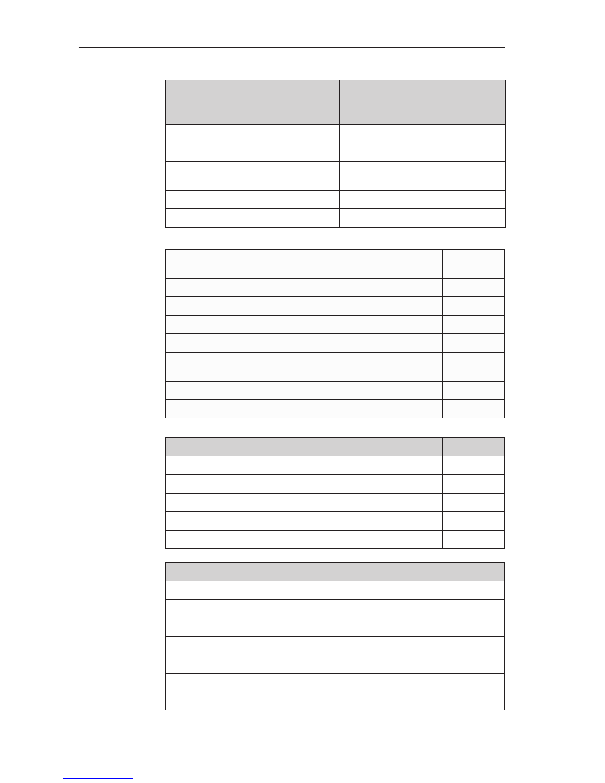
Velocity
based on dierential pressure measurement with Pitot tube
v
Typical measuring range 3 m/s - 100 m/s
Accuracy at 3 m/s 1 m/s
Accuracy > 12 m/s
(reading)
± 1%
Resolution 0,1 m/s
Absolute pressure measurement •
11.5.1 Data communication
USB interface master only (for connection to USB stick or
accessories)
Ο
Support of external SD card reader Ο
Ethernet, RJ45 Ο
WLAN Ο
Bluetooth Ο
RS485 (AUX socket, for connection of external sensor modules)
Ο
RS485 (isolated, for connection to PC) Ο
Analog I/O: 4x input, 8x output, 4... 20 mA Ο
11.5.2 Analysis and calculations
Continuous measured values
Unit
O
2
[%]
Temp. ambient air (thermocouple) [°C]
Temp. ue (thermocouple) [°C]
CO [ppm]
Draft [hPa]
Further continuously calculated values
Unit
ETA [%]
ETA condensed [%]
Losses [%]
Losses condensed [%]
Lambda -
Dew point [°C]
CO/CO2 ratio [%]
Page 35
MRU
35 / 44
MGA
prime
Version 1
Specications
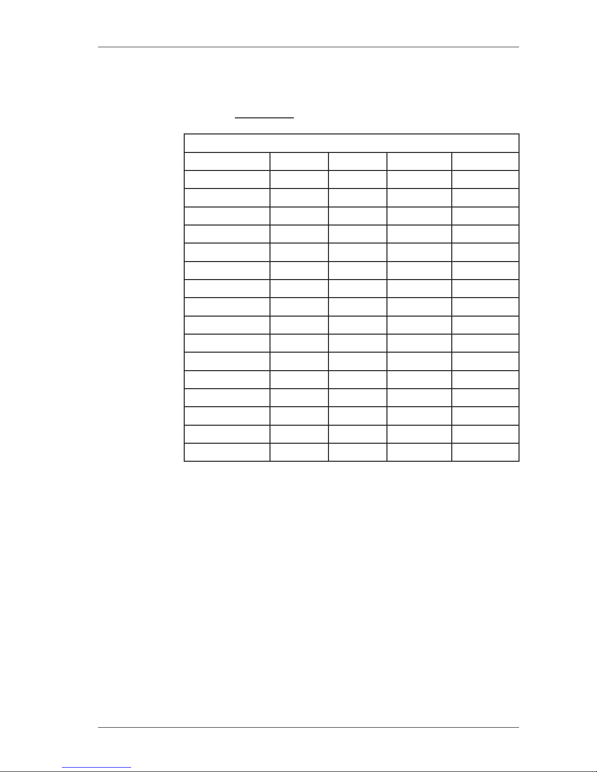
11.6 Fuel types
This list is for Germany only.
Fuel types from other countries can be obtained from MRU GmbH:
Web page: www.mru.eu
Germany O2max 20,96
Fuel CO2max A1 A2 B
Test gas 0,0 0,00 0,00 0,000
Natural gas (LL) 11,8 0,37 0,66 0,009
Natural gas (E) (*) 12,1 0,37 0,64 0,009
EL heating oil 15,4 0,50 0,68 0,007
S heating oil 15,9 0,50 0,66 0,007
P/B liquid gas 13,7 0,42 0,63 0,008
Propane 13,7 0,43 0,66 0,007
Butane 14,1 0,45 0,67 0,007
Biodiesel 15,7 0,46 0,62 0,005
Dry wood 20,3 0,60 0,62 0,009
Pellets 20,3 0,74 0,77 0,000
Coal 19,1 0,59 0,65 0,009
Lignite 19,4 0,39 0,42 0,009
Peat 19,8 0,66 0,70 0,010
Coke oven gas 10,8 0,29 0,60 0,011
Coal gas 11,7 0,35 0,63 0,011
Page 36

MRU
36 / 44
MGA
prime
Version 1
Appendix
12 Appendix
12.1 Error diagnosis regarding the measuring instrument
Fault indication Possible causes Repair
Gas cooler is faulty!
The system will shut
down…
Gas cooler faulty Contact MRU service
department
Undervoltage!!!
The System will shut
down…
Battery is discharged Connect instrument
to power grid.
Power consumption
too high”
Please check heated
hose!
Please check heated
sample line.
Heated sample line
may be damaged.
Disconnect the
instrument from
power grid and
visually inspect the
sample line. Take
care to unroll the
heated sample line
before operating it.
Hose temperature is
set to 160°C
Sample line
temperature set to
160 °C.
Heated sample line is
only intended to op-
erate at higher temperatures than 160
°C for short time. !
During next power-up the tempera-
ture is reduced to
160 °C again..
Please wait – pump is
o
Warm up has not been
completed yet.
Measurement not
started as instrument
is in warm-up phase..
Wait until warm
up phase has
terminated.
Flow monitoring!
Flow rate too low!
Please check lter
The sample gas ow
has fallen below the
required limit.
Filter or sample line
may be clogged.
Gas pump may be
faulty
Flow sensor may be
defect.
Check sample line
and all lters on dust
or water. Replace
lters.
Page 37
MRU
37 / 44
MGA
prime
Version 1
Appendix
Fault indication
Possible causes Repair
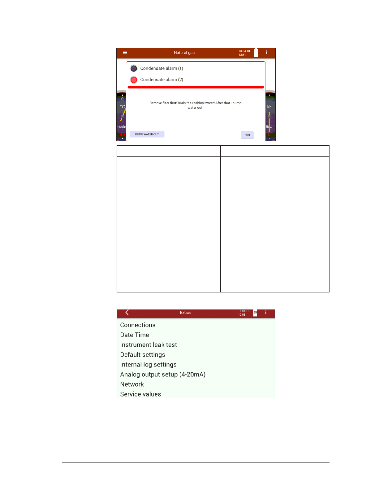
Condensate or water has been
detected behind the gas cooler
stage. To protect the sensors
the pump has been switched
o..
f To continue operation it has
to be ensured that no water
will be fed to the sensors.
f Remove sample line. Check
external lter on possible water content. Remove water
f Use the peristaltic pump to
drain water. Therefore press the
corresponding display button.
f Repeat if necessary.
f In a second step, if the pro-
ceeding steps removed all
water possibly present in the
gas cooler and hoses, the gas
pump may be used to dry out
remaining water droplets.
12.2 Insert a static IP-address
f Choose “network” in menu Extras.
Page 38

MRU
38 / 44
MGA
prime
Version 1
Appendix
f Put the switch on “DHVF is active””
f Choose the desired IP address, subnet mask, standard gateway and
preferred DNS server.
f Conrm with “OK”.
Ö The modication will be active after restart.
The input of subnet mask occurs to following principle:
Page 39
MRU
39 / 44
MGA
prime
Version 1
Appendix
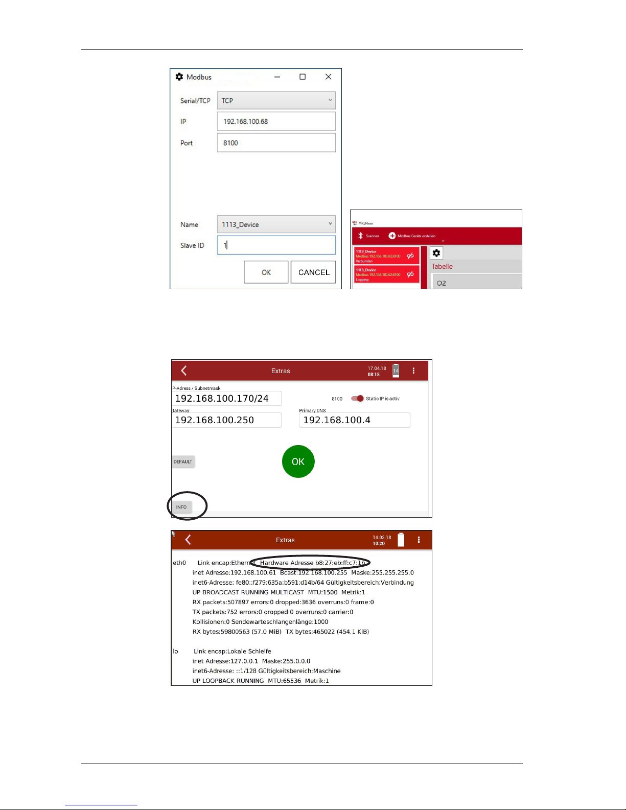
12.2.1 Settings for the software MRU4win
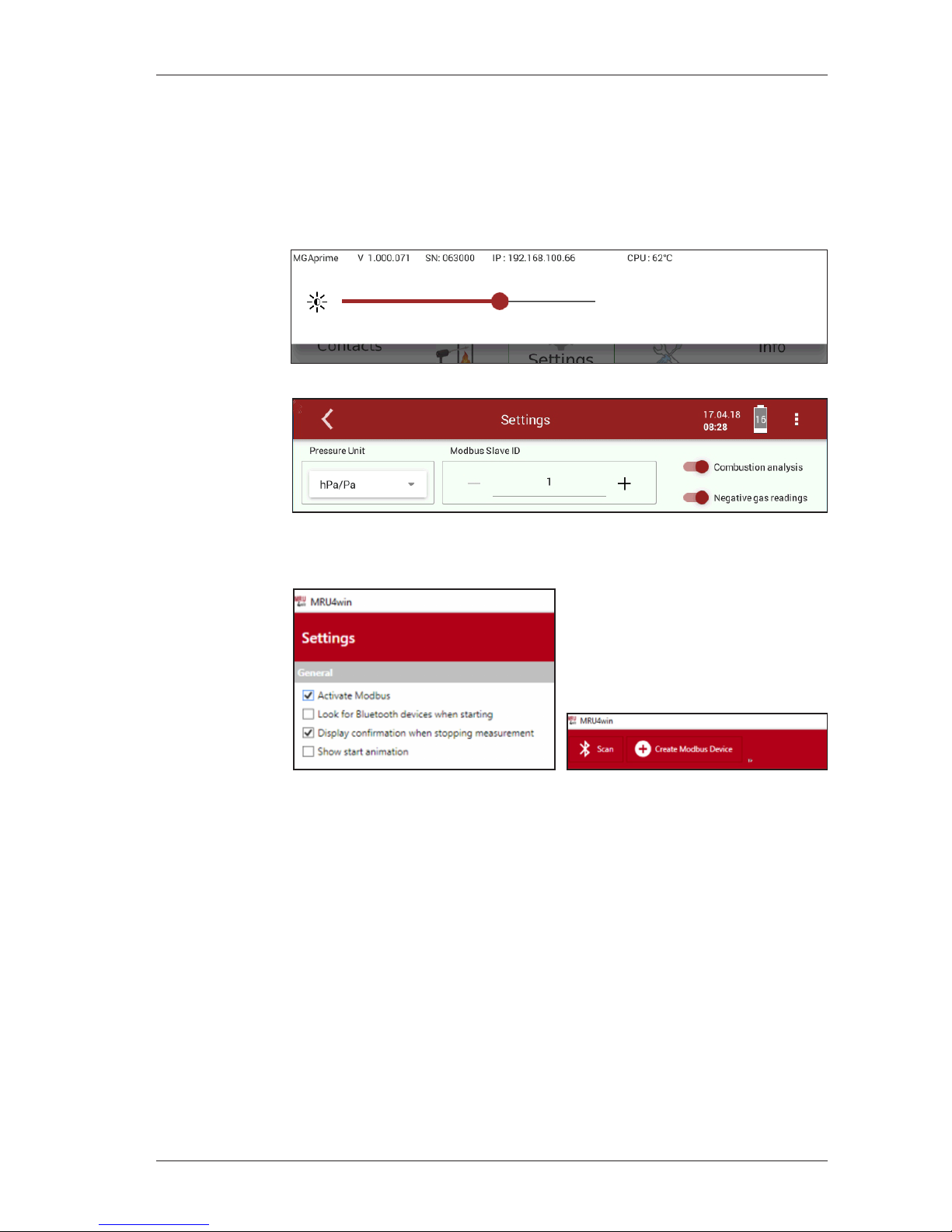
The PC program MRU4win can be used for a LAN connection of the analyzer.
f Connect the analyzer with the network.
Read the IP address
f Select the “display setting” in the main menu using the context key.
Ö The IP address is shown at the top line.
f Modbus slave ID set to 1.
Adjust MRU 4 Win to PC
f The Modbus must be activated in the Setting menu
f „Create a Modbus Device“
Page 40
MRU
40 / 44
MGA
prime
Version 1
Appendix
f The IP address of the analyzer must be inserted.
Ö After these settings, the analyzer connect to the PC.
Info about the network
Page 41
MRU
41 / 44
MGA
prime
Version 1
Appendix
12.3 Spare parts
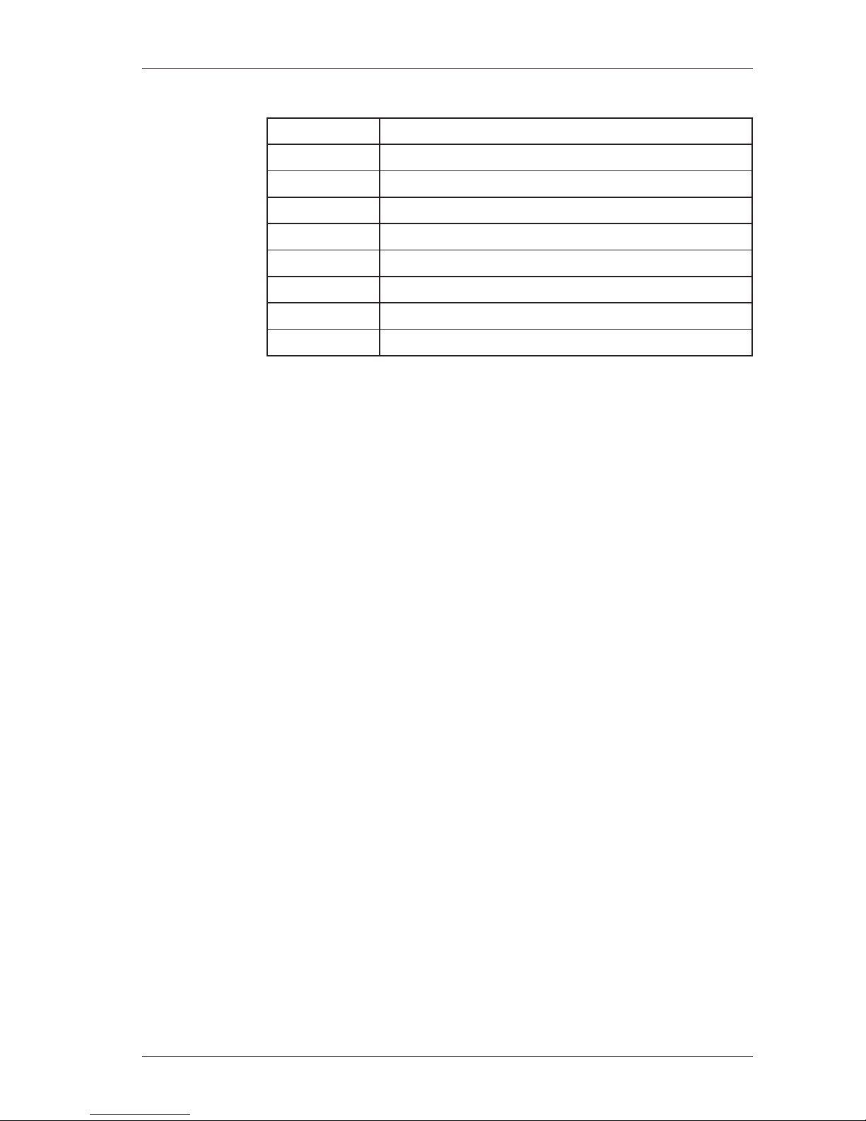
Part number Spare part
56879A PTFE Round lter
61158 Probe lter sintered metal 2 µm
61157 Probe lter sintered metal 20 µm
10825 Mineral wool lter element
59799 O-ring 16 x 1,5
61066 O-ring 12 x 2
61333
O-ring 10 x 2
60074 O-ring 8 x 2
Page 42

MRU
42 / 44
MGA
prime
Version 1
Declaration of conformity
13 Declaration of conformity
Page 43

Page 44

 Loading...