

Page 1
MRU GmbH USER MANUAL MFplus Part 2 OPTION TRGI
1
Page 2

MRU GmbH USER MANUAL MFplus Part 2 OPTION TRGI
Page 3

MRU GmbH USER MANUAL MFplus Part 2 OPTION TRGI
1 Table of content
1 Table of content ...................................................................................................................................................................3
2 Introduction .........................................................................................................................................................................5
3 Pipe tests(TRGI)....................................................................................................................................................................6
3.1 Stress test..................................................................................................................................................................7
3.1.1 Connection diagram stress test LOAD side only ...................................................................................................8
3.1.2 Connection diagram stress test LOAD side and GAS supplier side .......................................................................9
3.1.3 Operation ...........................................................................................................................................................10
3.1.3.1 Apply pressure..........................................................................................................................................10
3.1.3.2 Adaption phase ........................................................................................................................................10
3.1.3.3 Test phase ................................................................................................................................................11
3.1.3.4 View results..............................................................................................................................................11
3.1.3.5 Save results ..............................................................................................................................................12
3.2 Leak-tightness test ..................................................................................................................................................13
3.2.1 Connection diagram leak-tightness test LOAD side only....................................................................................14
3.2.2 Connection diagram leak-tight test Load side and Gas supplier side .................................................................15
3.3 Operation ................................................................................................................................................................16
3.3.1.1 Apply pressure..........................................................................................................................................16
3.3.1.2 Adaption phase ........................................................................................................................................16
3.3.1.3 Test phase ................................................................................................................................................16
3.3.1.4 View results..............................................................................................................................................17
3.4 Usage capability tests..............................................................................................................................................18
3.4.1 Connection diagram usage capability test LOAD side only.................................................................................19
3.4.2 Connection diagram usage capability test without dismounting gas meter .......................................................20
3.4.3 Connection diagram usage capability test LOAD side only test with air.............................................................21
3.4.4 Connection diagram usage capability test LOAD side and Gas supplier side test with air .................................22
3.4.5 Connection diagram example with the optional Black box TRGI........................................................................23
3.4.6 Operation ...........................................................................................................................................................24
3.4.6.1 Automatic capacity determination using the optional Black box TRGI (Option).......................................24
3.4.6.2 Automatic capacity determination ...........................................................................................................25
3.4.6.3 Enter pipe capacity manually ...................................................................................................................26
3.4.6.4 Enter all other parameters........................................................................................................................26
3.4.6.5 Apply test pressure...................................................................................................................................26
3.4.6.6 Adaption phase ........................................................................................................................................27
3.4.6.7 Test phase ................................................................................................................................................27
3.4.6.8 View results..............................................................................................................................................27
3.4.6.9 Save results ..............................................................................................................................................28
3.5 Pipe tests TRGI 50 mbar..........................................................................................................................................30
3.5.1 Connection diagram pipe test ............................................................................................................................30
3.5.2 Operation ...........................................................................................................................................................30
3.5.2.1 Apply pressure..........................................................................................................................................31
3
Page 4

MRU GmbH USER MANUAL MFplus Part 2 OPTION TRGI
3.5.2.2 Adaption phase ........................................................................................................................................31
3.5.2.3 Pressure test.............................................................................................................................................31
3.6 Liquid gas pipes (TRF) .............................................................................................................................................32
3.6.1 Operation ...........................................................................................................................................................32
3.6.2 Stability test TRF.................................................................................................................................................33
3.6.2.1 Apply pressure..........................................................................................................................................33
3.6.2.2 Adaption phase ........................................................................................................................................34
3.6.2.3 Pressure test.............................................................................................................................................34
3.6.3 Leak-tight test (TRF)...........................................................................................................................................35
3.6.3.1 Apply pressure..........................................................................................................................................35
3.6.3.2 Adaption phase ........................................................................................................................................35
3.6.3.3 Pressure test.............................................................................................................................................36
4 Accessories.........................................................................................................................................................................37
4.1 Measuring accessory- Set 1, for ONE pipe gas meter # 61500 ................................................................................37
4.2 Measuring accessory- Set 2, for TWO pipe gas meter # 61501 ...............................................................................37
4.3 Connection set SMALL only for usage capability test # 64072 ................................................................................37
4.4 Additional accessory ...............................................................................................................................................37
4.5 Optionen .................................................................................................................................................................38
5 Technical details MFplus Option TRGI................................................................................................................................39
5.1 Sensor specifications pressure measurement ..........................................................................................................39
5.2 Calculated value gas leakage rate...........................................................................................................................39
5.3 Additional specifications .........................................................................................................................................39
6 Usage capability test..........................................................................................................................................................40
6.1 What is a Usage capability test ...............................................................................................................................40
6.2 Connection diagram Usage capability test without dismounting gas meter using SET #64072 (small)...................41
6.3 Operation ................................................................................................................................................................42
6.3.1 Automatic capacity determination .....................................................................................................................42
6.3.2 Enter pipe capacity manually .............................................................................................................................43
6.3.3 Enter all other parameters..................................................................................................................................43
6.3.4 Apply test pressure.............................................................................................................................................43
6.3.5 Adaption phase ..................................................................................................................................................44
6.3.6 Test phase ..........................................................................................................................................................44
6.3.7 View results........................................................................................................................................................45
6.3.8 Save results ........................................................................................................................................................46
4
Page 5

MRU GmbH USER MANUAL MFplus Part 2 OPTION TRGI
2 Introduction
This manual is an important element of the delivery and explains in detail how to operate the MFplus but also
ensures the safety of the user and protects the environment.
This manual „USER MANUAL MFplus Part2 TRGI“ only addresses the TRGI functions.
For the general operation of the MFplus the manual „USER MANUAL MFplus” is essential!
It is the duty of each user to get familiar with the contents of these manuals and to follow the directions
especially regarding security.
This device must always be used according to the latest DVGW regulations!
The MFplus TRGI is used to determine gas leakage in low pressure gas tubes according to DVGW-worksheet G
600 (DVGW-TRGI)
The gas leakage rate will be determined according to device class D based on the pressure drop.
For the pressure the unit mbar and bar are used.
1 mbar <> 1 hPa
Before starting a measurement the device and accessories must be inspected for any damages. A
measurement is only possible after the zeroing procedure has been accomplished successfully.
The zeroing takes between 1 and 3 minutes (depending on sensor condition) and should be made in the
recommended measuring position.
For best visibility and operation the device can either be lying flat on the back or can be hanging using the
rear magnets. The position of the device doesn’t influence the test results (accuracy).
OVERLOAD
ATTENTION:
The device is protected against overload up to 2 Bar. In case the overload value is exceeded the pressure
sensor can be destroyed. In that case the warranty for this device will expire.
Calibration
The MFplus TRGI must be calibrated on a yearly basis.
5
Page 6
MRU GmbH USER MANUAL MFplus Part 2 OPTION TRGI
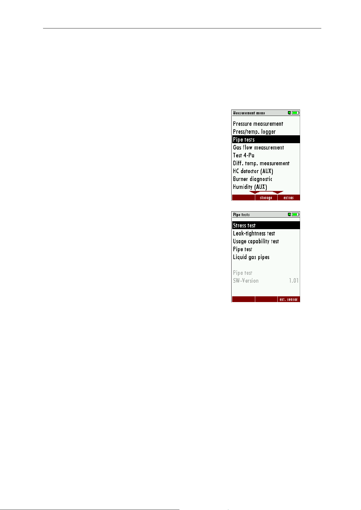
3 Pipe tests(TRGI)
The option pipe test (TRGI) includes the following tests:
• PRE test on gas pipes according to TRGI G 600
• Leak tightness test on gas pipes according to TRGI G 600
• Usage capability test- / Leakage rete measurement according to TRGI G 600, incl. determination of
the pipe capacity
In the Measurement menu select Pipe test and confirm with OK
In the menu Pipe tests select the desired test and confirm with OK.
6
Page 7

MRU GmbH USER MANUAL MFplus Part 2 OPTION TRGI
3.1 Stress test
The stress test serves as loading test of the materials.
All new installed pipes will be tested without the use of faucets. All pipe ends must be closed with metal
plugs or caps.
Exception: The stress test can be carried out with faucets if their maximal pressure range is equivalent or
higher than the test pressure.
The stress test should be done as long as the pipes are still accessible and before they are covered with any
anti-freeze protection.
The test pressure is 1 bar (1.000 hPa).
The test medium is either air or a not burnable gas, NO Oxygen!
The test phase is usually 10 minutes. Temperature compensation is not mandatory but dependent on the
length of the pipes and the temperature difference between the test medium and the pipes - temperature
compensation is recommended.
Thereafter, the test pressure may not decrease within 10 minutes. During the test phase the pipes are to be
visually inspected, connections and junctions should be mechanically stressed.
It is forbidden to connect any test pipes with gas filled pipes!!
On the following pages different connection diagrams are shown.
7
Page 8
MRU GmbH USER MANUAL MFplus Part 2 OPTION TRGI
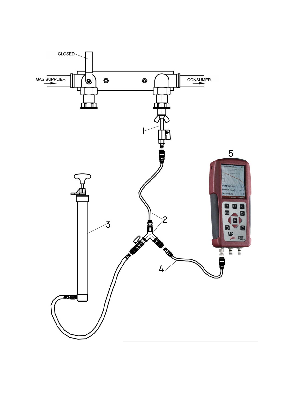
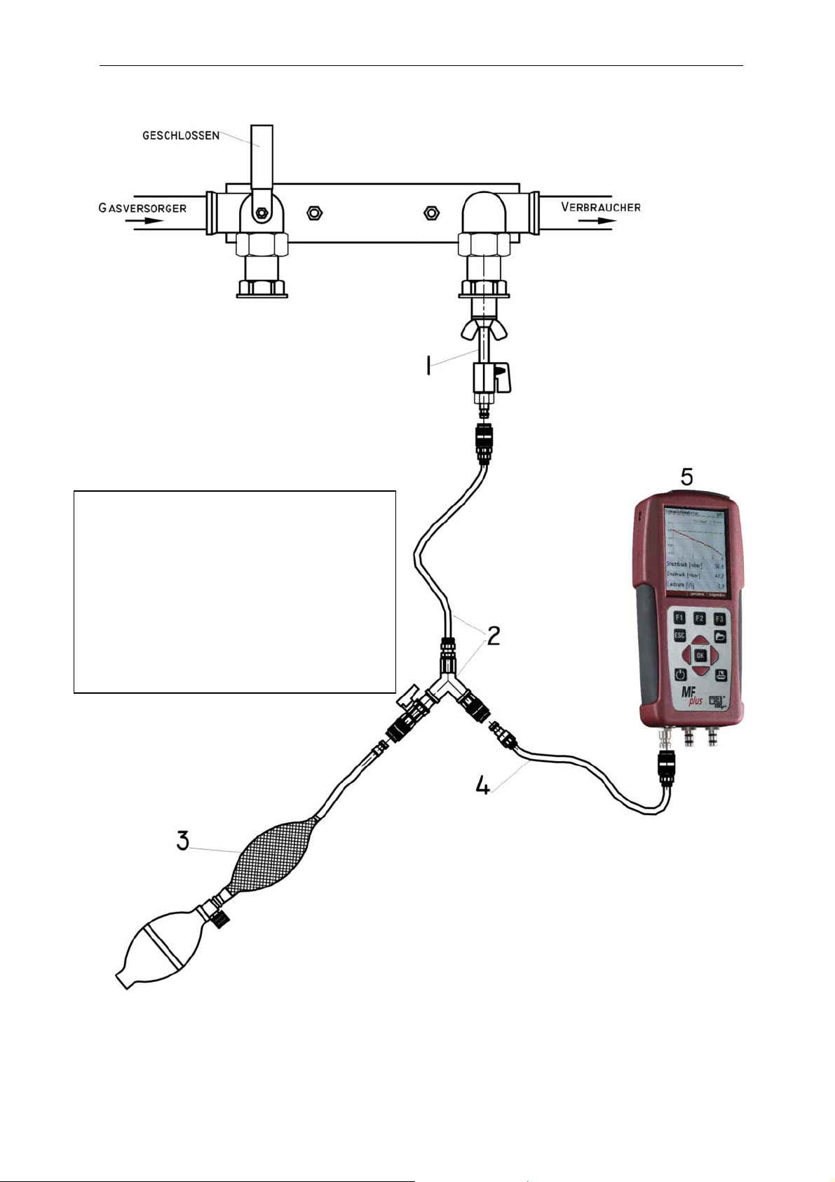
3.1.1 Connection diagram stress test LOAD side only
1 # 59148 Test plug
2 # 59074 Y-Divider with tap
3 # 59072 Hand pump
4 # 59076 Hose from MFplus to divider
5 MFplus
8
Page 9
MRU GmbH USER MANUAL MFplus Part 2 OPTION TRGI
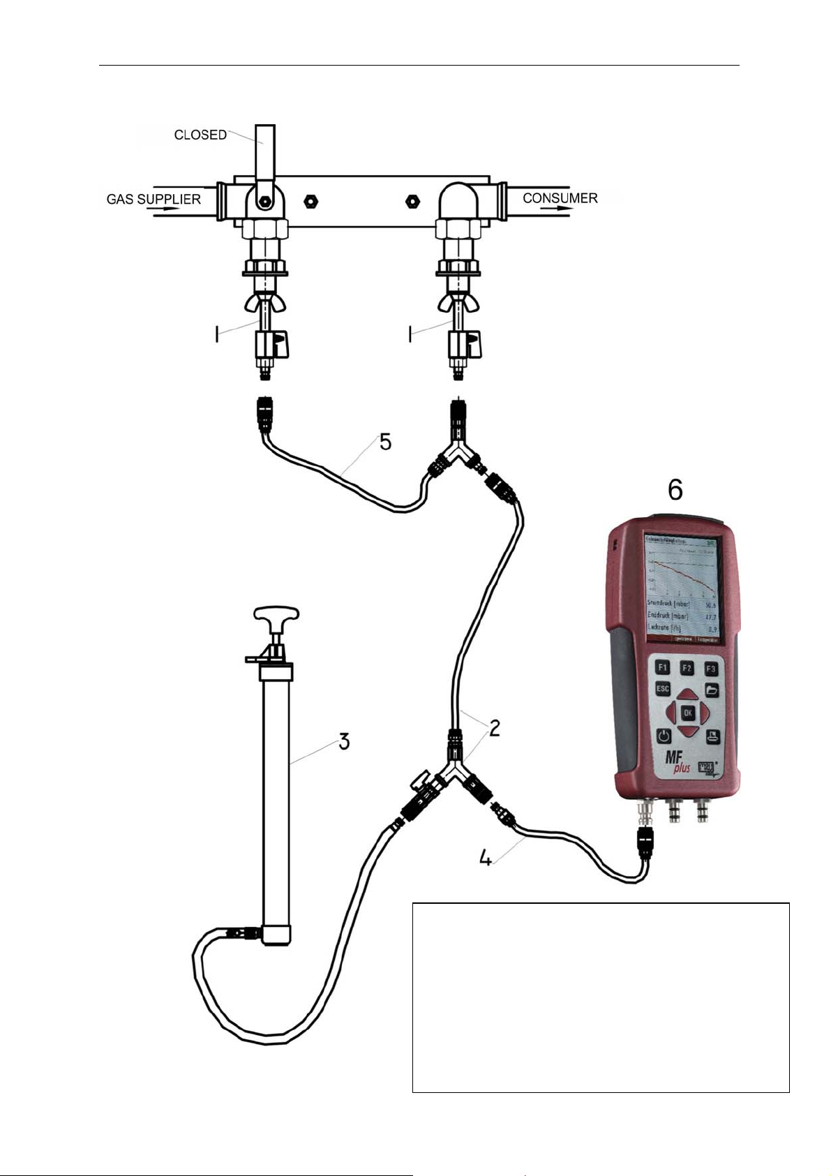
3.1.2 Connection diagram stress test LOAD side and GAS supplier side
1 # 59148 Test plug (2x)
2 # 59074 Y-Divider with tap and hose
3 # 59072 Hand pump
4 # 59076 Hose from MFplus to divider
5 # 59320 Y-Divider without tap with hose
6 MFplus
9
Page 10
MRU GmbH USER MANUAL MFplus Part 2 OPTION TRGI
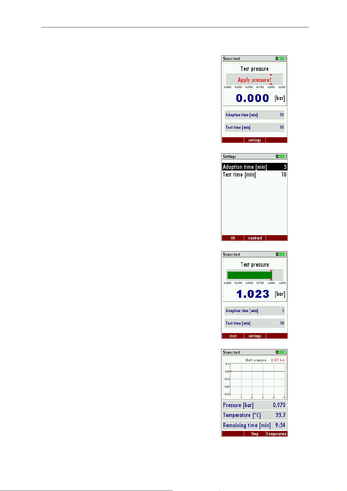
3.1.3 Operation
3.1.3.1 Apply pressure
In this screen you will apply pressure to the pipe you want to test.
Using the hand pump you will apply pressure (air) with open tap at the
Y-divider (2).
Times can be modified with the F2 button.
Times between 1 minute and 80 minutes are selectable.
The default value is 10 minutes.
Once the test pressure of 1 Bar is reached, the bar on the screen turns
green and the tap at the Y-divider (2) must be closed. With F1 the test
will be started.
3.1.3.2 Adaption phase
The adaption phase can be shortened at any time using the F1 button.
With F3 the temperature curve will be displayed.
Once the adaption phase is completed the stress test will start
automatically.
10
Page 11
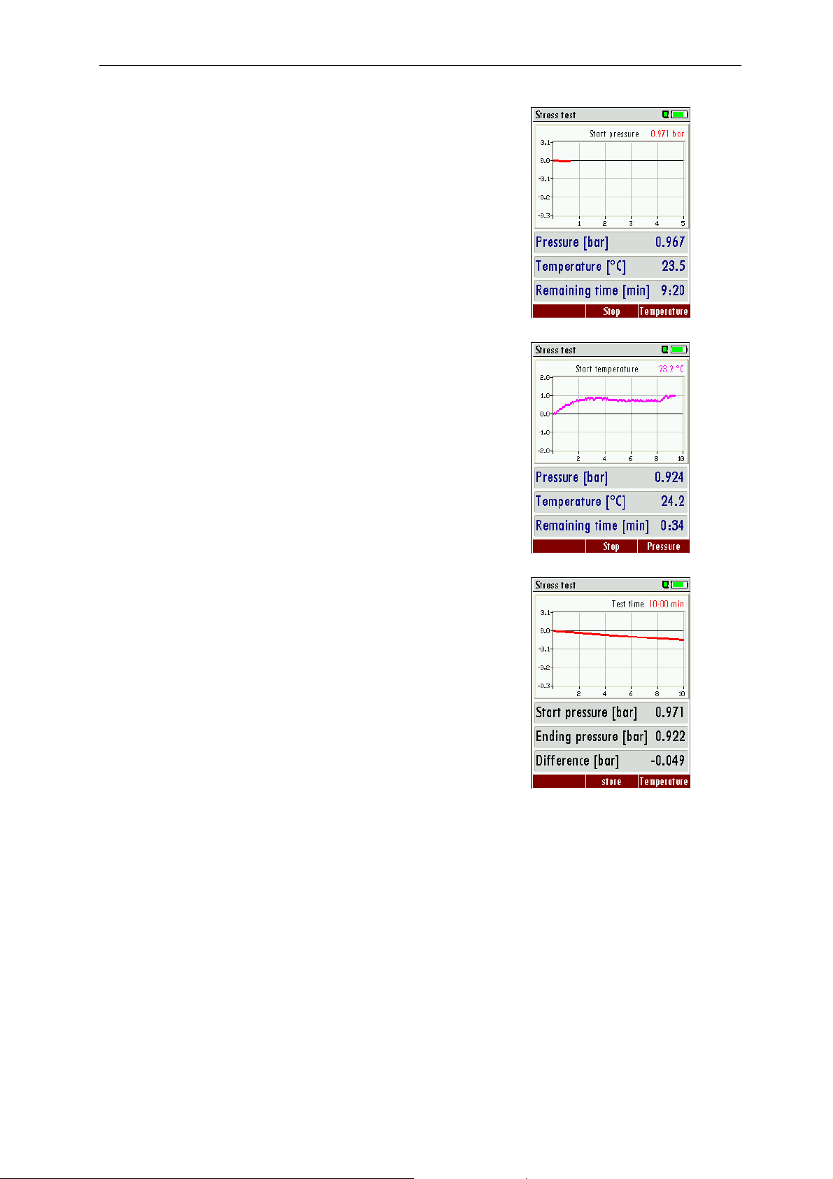
MRU GmbH USER MANUAL MFplus Part 2 OPTION TRGI
3.1.3.3 Test phase
Now the stress test is in operation. Also here F3 will make the
temperature curve visible.
The temperature curve will help judging the test result. A decreasing
temperature during the test phase can result in a low pressure drop.
There is no automatic pressure/temperature compensation!
3.1.3.4 View results
At the end of the test the start pressure, end pressure and pressure
difference will be displayed.
With the printer button the results can be printed.
With the F2 button the results can be saved.
With ESC you will return to the measuring menu.
11
Page 12
MRU GmbH USER MANUAL MFplus Part 2 OPTION TRGI
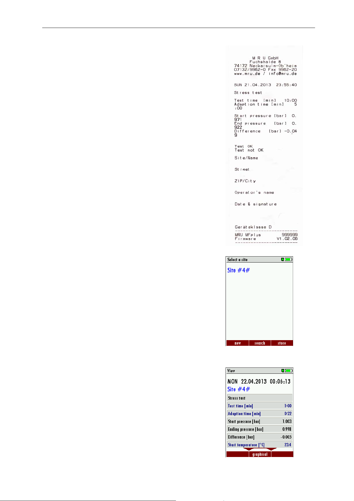
Example print-out of a Stress test
3.1.3.5 Save results
Here you will select the site under which the results will be saved.
Press F3 to save the results to the site.
Saved results can be viewed again.
With ESC you will return to the measuring menu.
12
Page 13

MRU GmbH USER MANUAL MFplus Part 2 OPTION TRGI
3.2 Leak-tightness test
With the leak-tightness test smallest leaks can be made vissible.
The pipes with all faucets are tested, however without gas units and their regulators and security devices. The
gas meter can be included in this test.
The leak-tight test should be done as long as the pipes are still accessible and before they are covered with
any anti-freeze protection.
Test pressure: 150 mbar (150 hPa)
Test medium: Air or inert gas
Test duration: Dependent on the pipe capacity one must consider the adaption time and a
minimum test duration time is mandatory
Pipe capacity: Adaption phase: Test duration:
<100l 10min 10min
>=100 <200l 30min 20min
>=200l 60min 30min
On the following pages different connection diagrams are shown.
13
Page 14
MRU GmbH USER MANUAL MFplus Part 2 OPTION TRGI
3.2.1 Connection diagram leak-tightness test LOAD side only
1 # 59148 Test plug
2 # 59074 Y-divider with tap and hose
3 # 59071 Pump ball with outlet valve and
balancing balloon
4 # 59076 Hose from MFplus to Y-divider
5 MFplus
14
Page 15
MRU GmbH USER MANUAL MFplus Part 2 OPTION TRGI
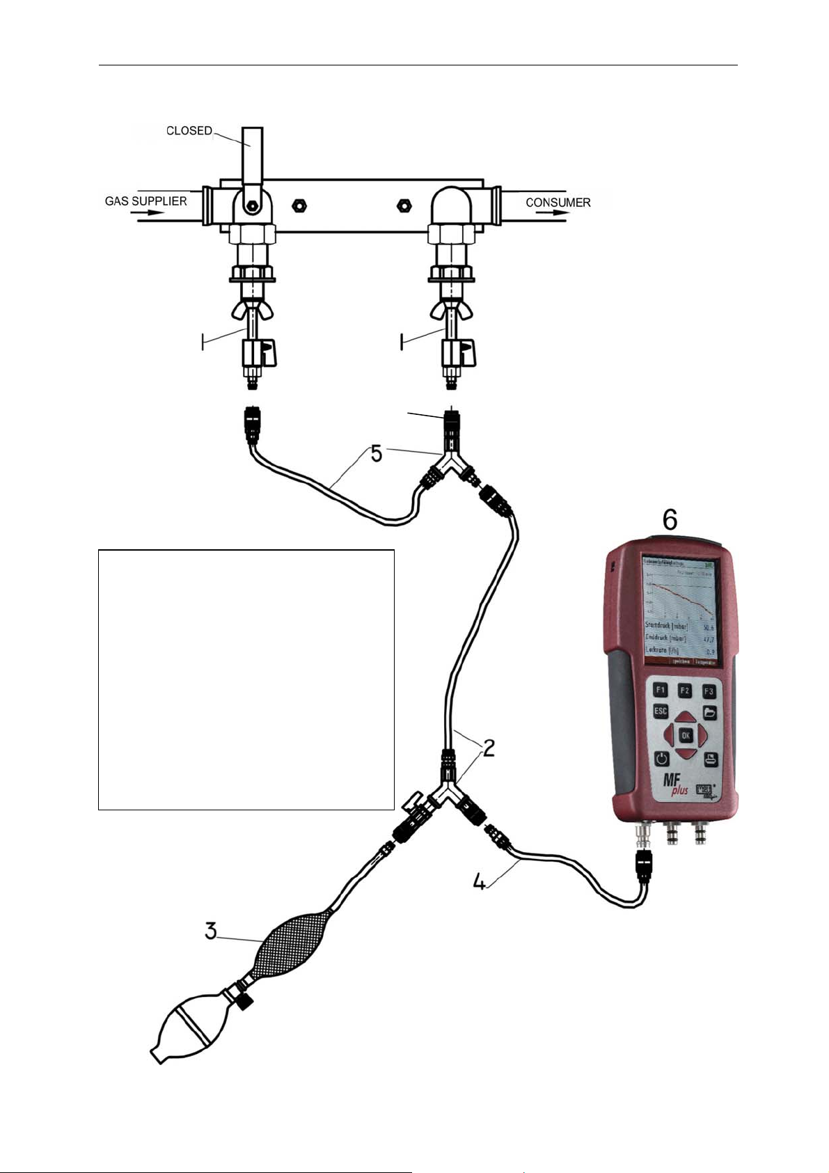
3.2.2 Connection diagram leak-tight test Load side and Gas supplier side
1 # 59148 Test plug (2x)
2 # 59074 Y-divider with tap and hose
3 # 59076 Pump ball with outlet valve
and balancing balloon
4 # 59071 Hose from MFplus to Y-
divider
5 # 59320 Y-divider without tap with
hose
6 MFplus
15
Page 16
MRU GmbH USER MANUAL MFplus Part 2 OPTION TRGI
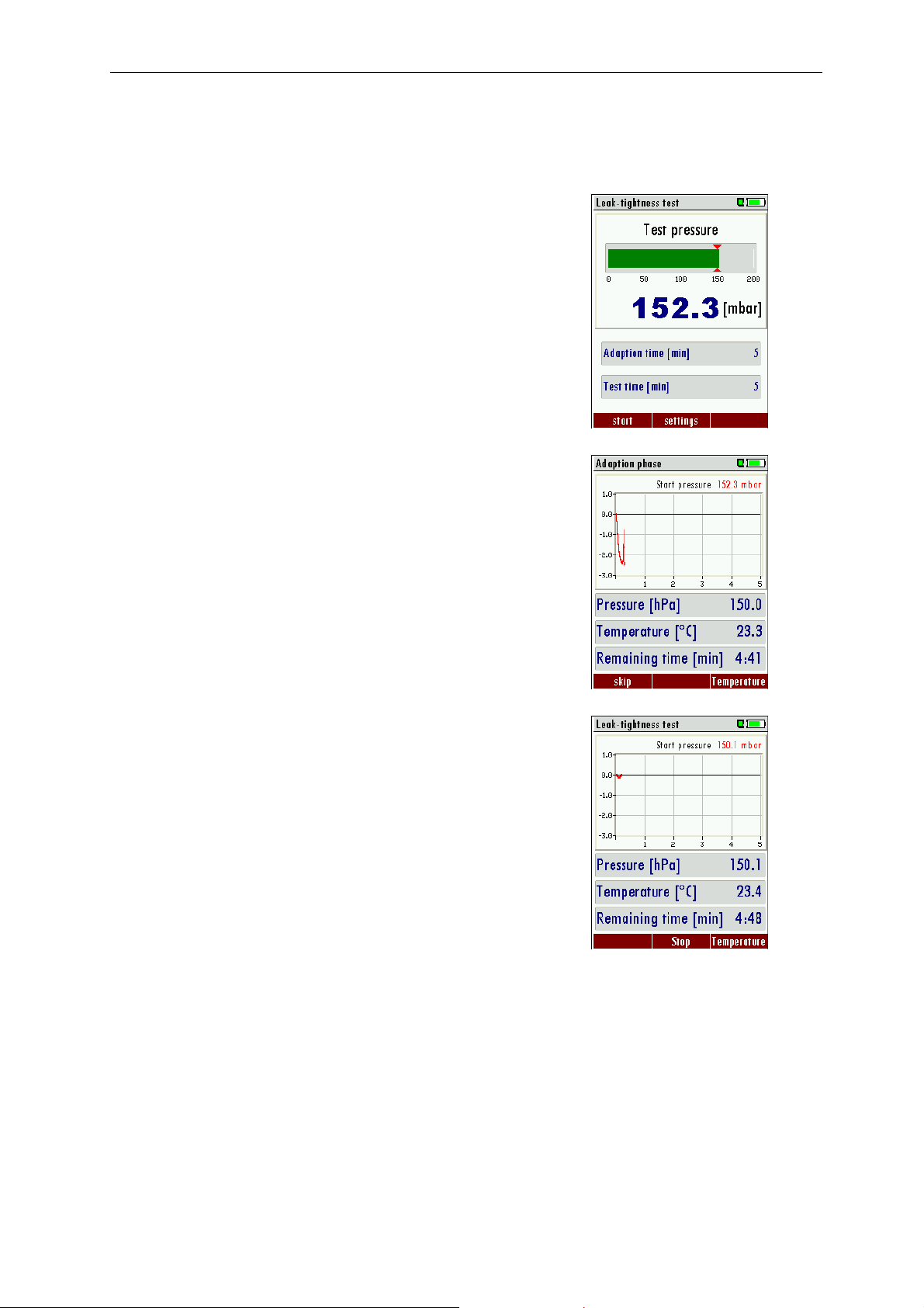
3.3 Operation
3.3.1.1 Apply pressure
In this screen you will apply pressure to the pipe you want to test.
Pump air into the system using the pump ball – tap at Y-divider (2)
must be open.
Once the test pressure of 150 mbar is reached, the bar on the screen
turns green and the tap at the Y-divider (2) must be closed. With F1 the
test will be started.
3.3.1.2 Adaption phase
The adaption phase can be shortened at any time using the F1 button.
With F3 the temperature curve will be displayed.
Once the adaption phase is completed the leak-tight test will start
automatically.
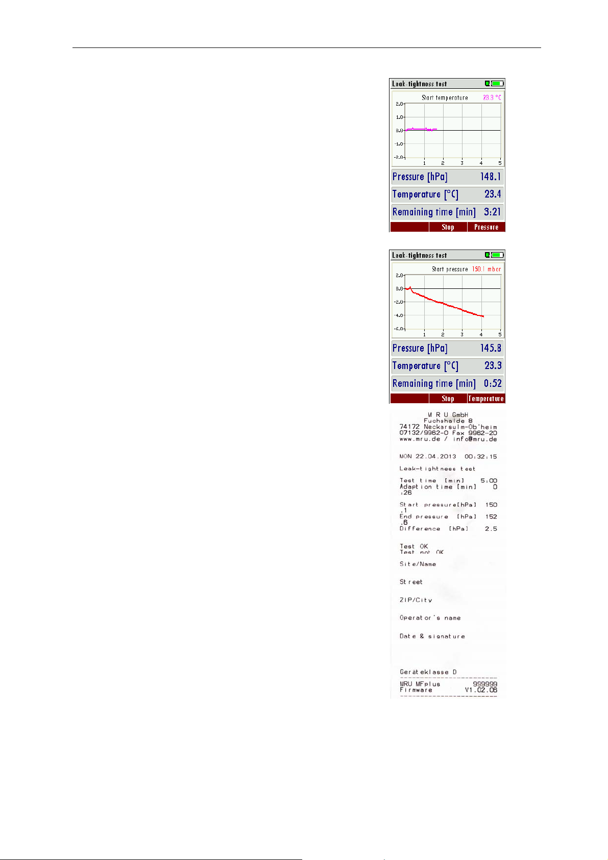
3.3.1.3 Test phase
Now the stress test is in operation. Also here F3 will make the
temperature curve visible.
16
Page 17
MRU GmbH USER MANUAL MFplus Part 2 OPTION TRGI
The temperature curve will help judging the test result. A decreasing
temperature during the test phase can result in a low pressure drop.
There is no automatic pressure/temperature compensation!
3.3.1.4 View results
At the end of the test the start pressure, end pressure and pressure
difference will be displayed.
With the printer button the results can be printed.
With the F2 button the results can be saved.
With ESC you will return to the measuring menu.
Example print-out of a leak-tight test
17
Page 18

MRU GmbH USER MANUAL MFplus Part 2 OPTION TRGI
3.4 Usage capability tests
The Usage capability test helps to determine and judge leakages (gas leakage) in low pressure gas pipes.
Tested will be all in operation or repaired pipes with all faucets, however without gas units and their
regulators and security devices. The gas meter can be included in this test (using backward test).
The usage capabilities test my not be performed when:
- New installed pipes (= pipes within warranty)
- Pipes that had a limited usage capability or a NO usage capability and had been repaired to be used
- Not in use pipes which want to be used again
- Pipes in middle- and high pressure range.
Test medium: Air or Methane
Test pressure: 23 mbar according to DVGW worksheet G600.
Unlimited usage capability: > 0 l/h to < 1,0 l/h
The pipe can be used for unlimited time without repair.
Limited usage capability: >1,0 l/h up to < 5,0 l/h
The pipe may be used for a maximum of 4 weeks. Within these 4 weeks the pipe must be repaired to achieve
Unlimited Usage Capacity again (Leak-tight test).
NO usage capability: > 5,0 l/h
The use of this pipe must be stopped immediately. Take action to determine the defect.
Important is the technical security judgment:
Also a leak tight gas pipe can have limited or no usage capability. The physical condition must be considered
as well!
Once you smell gas the system is leaking. The above mentioned usage capability grading’s do not apply.
18
Page 19
MRU GmbH USER MANUAL MFplus Part 2 OPTION TRGI
On the following pages different connection diagrams are shown.
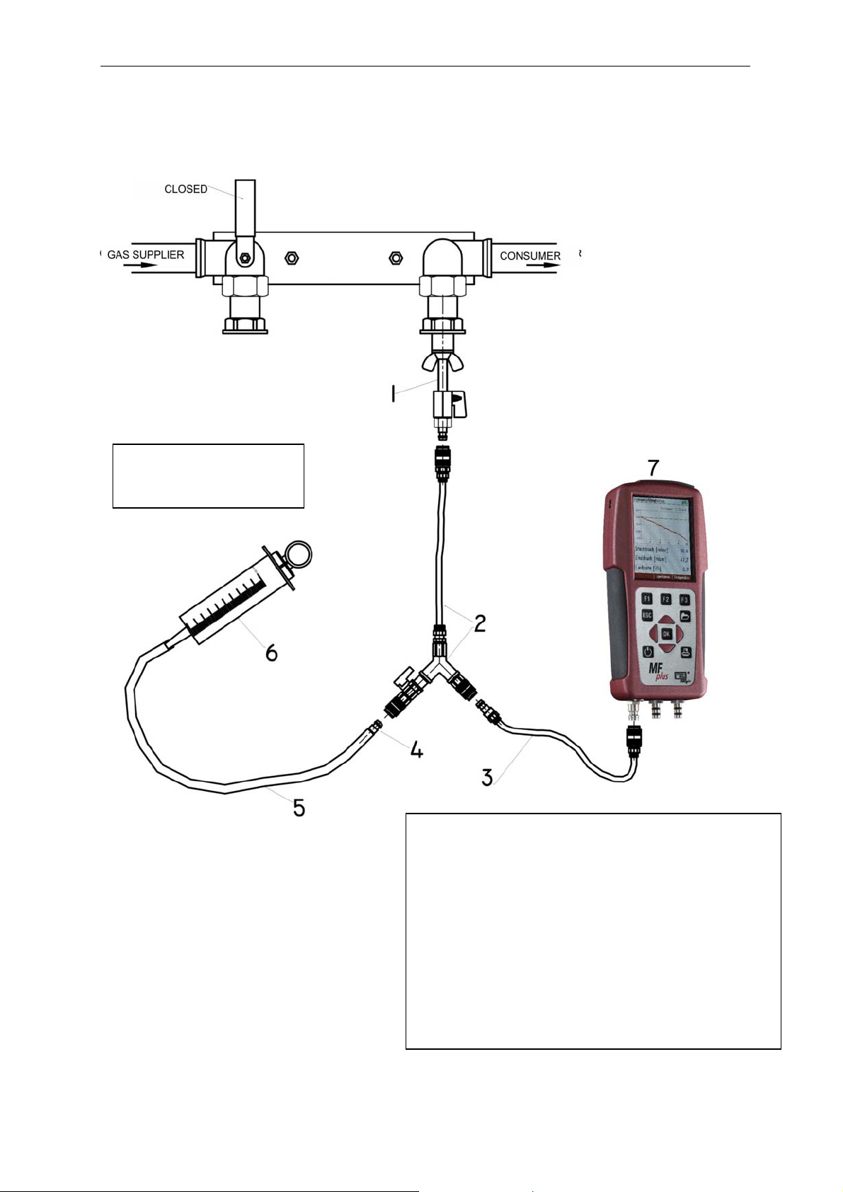
3.4.1 Connection diagram usage capability test LOAD side only
108 ml =
syringe NOT pulled
1 # 59148 Test plug
2 # 59074 Y-Divider with tap and hose
3 # 59076 Hose from MFplus to Y-divider
4 #59038 Connector
5 #50482 Silicone hose
6 # 61499 Syringe
7 MFplus
19
Page 20
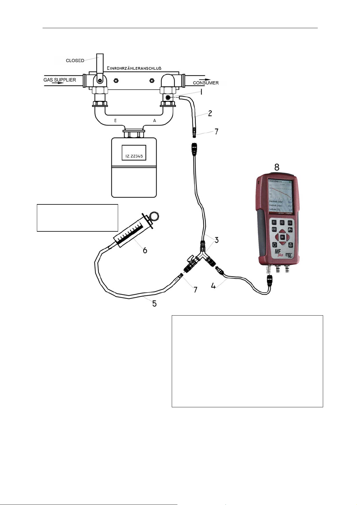
MRU GmbH USER MANUAL MFplus Part 2 OPTION TRGI
p
3.4.2 Connection diagram usage capability test without dismounting gas meter
108 ml =
Syringe NOT pulled
1 # 59387 Test connection
2 # 50482 Silicone hose
3 # 59074 Y-Divider with tap and hose
4 # 59076 Hose from MFplus to Y-Divider
5 # 50482 Silicone hose
6 # 61499 Syringe
7 # 59038 Connector
8MF
20
lus
Page 21
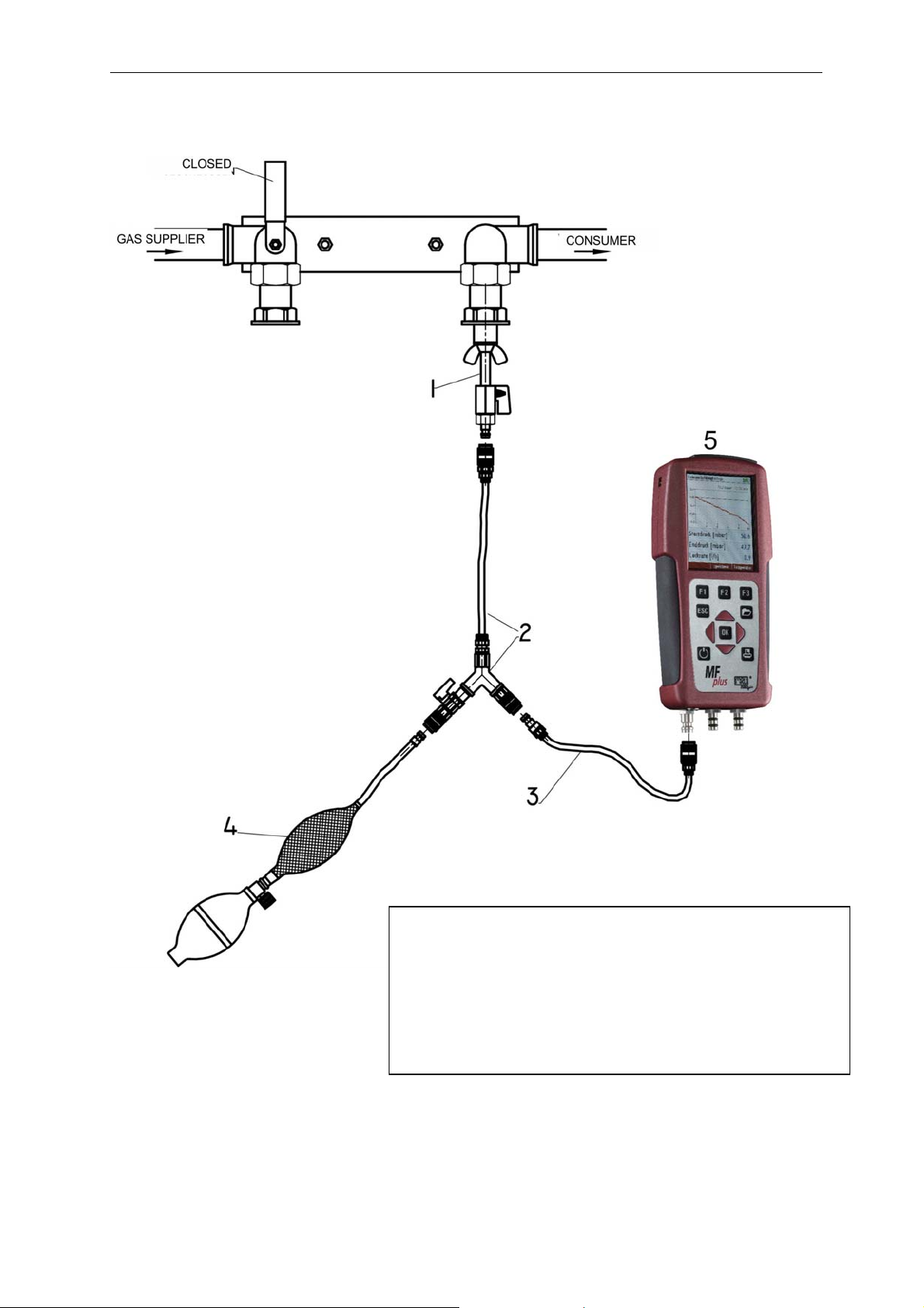
MRU GmbH USER MANUAL MFplus Part 2 OPTION TRGI
3.4.3 Connection diagram usage capability test LOAD side only test with air
1 # 59148 Test plug
2 # 59074 Y-Divider with tap and hose
3 # 59076 Hose from MFplus to Y-Divider
4 # 59071 Pump ball with outlet valve and balancing balloon
5 MFplus
21
Page 22
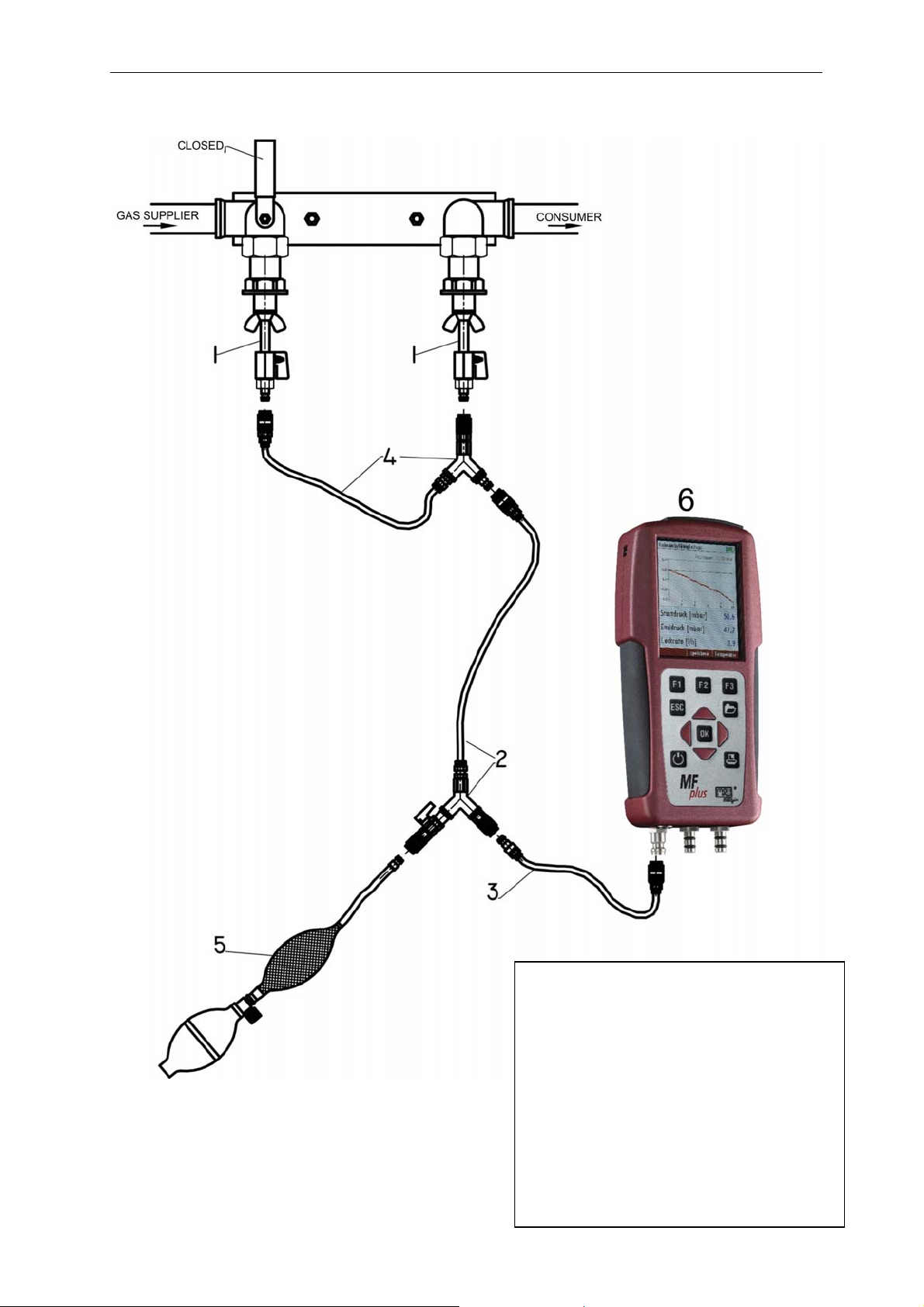
MRU GmbH USER MANUAL MFplus Part 2 OPTION TRGI
3.4.4 Connection diagram usage capability test LOAD side and Gas supplier side test with air
22
1 # 59148 Test plug (2)
2 # 59074 Y-Divider with hose
3 # 59076 Hose from MFplus to Y-
Divider
4 #59320 Y-Divider without tap
5 # 59071 Pump ball with outlet valve
and balancing balloon
6 MFplus
Page 23
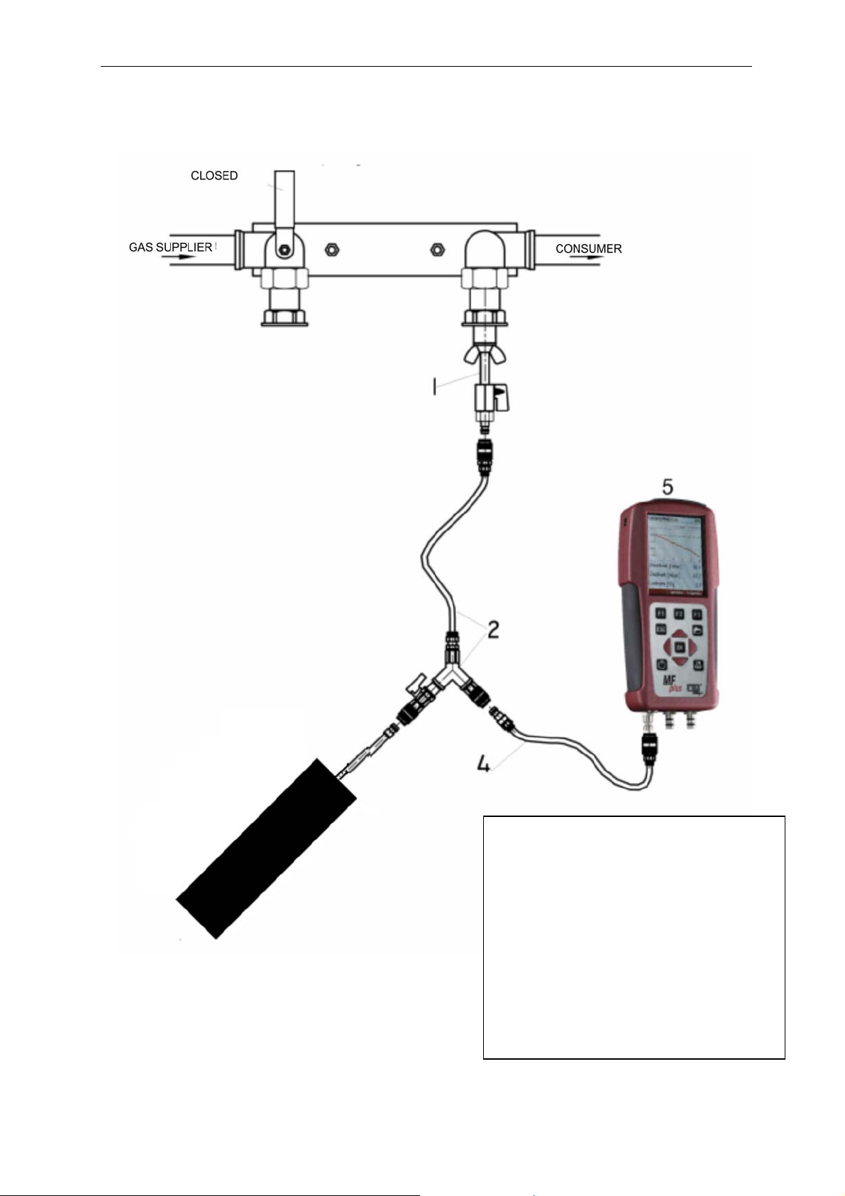
MRU GmbH USER MANUAL MFplus Part 2 OPTION TRGI
3.4.5 Connection diagram example with the optional Black box TRGI
3
23
1 # 59148 Test plug (1)
2 # 59074 Y-Divider with hose
3 #64322 Black box TRGI
4 # 59076 Hose from MFplus to Y-
Divider
4 #59320 Y-Divider without tap
5 #913003 MFplus
Page 24
MRU GmbH USER MANUAL MFplus Part 2 OPTION TRGI
3.4.6 Operation
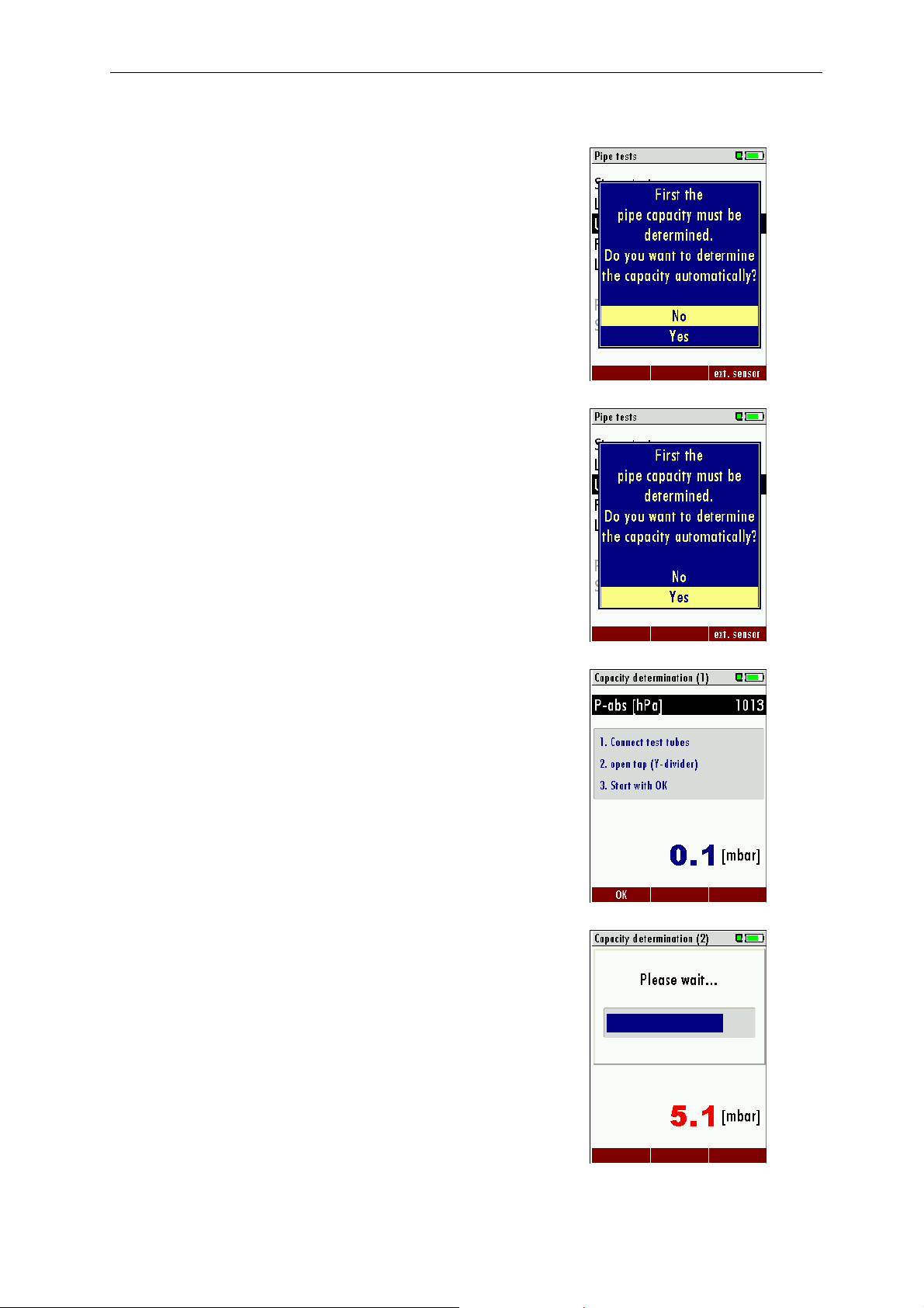
To be able to calculate the leakage rate first the pipe capacity must be
determined.
In the first screen of the usage capability test you are asked if you want
to determine the pipe capacity automatically. As alternative you can
insert the pipe capacity manually.
No – continue with 3.4.6.4 Enter pipe capacity manually
3.4.6.1 Automatic capacity determination using the
optional Black box TRGI (Option)
Select usage capability test
Set cursor on „Yes“. Confirm with the OK-Button.
Connect the Black box TRGI to the MFplus
(see diagram Fehler! Verweisquelle konnte nicht gefunden
werden.).
IMPORTANT: open the Y-Divider tap!
Confirm with the OK-button.
24
Page 25
MRU GmbH USER MANUAL MFplus Part 2 OPTION TRGI
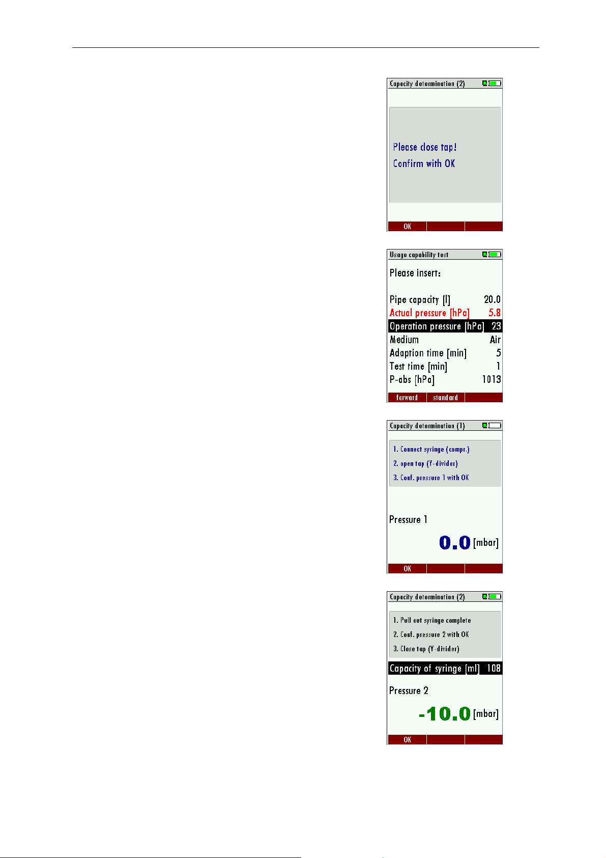
Wait till the pipe capacity has been determined.
Close the Y-Divider tap. Confirm with the OK- Button.
The determined pipe capacity will be displayed in Liter.
Press F1 to continue the usage capability test.
Enter all other parameters see chapter 3.4.6.4
3.4.6.2 Automatic capacity determination
The capacity determination using the syringe is performed by extracting
a defined capacity (syringe) from the closed pipe system. From the
resulting pressure drop the MFplus calculates the pipe capacity.
When using diagram 3.4.1 start pressure 1 will be +/- 0 mbar.
When using diagram 6.2 start pressure 1 will be operation pressure
(23 mbar).
Please follow the instructions on the display.
When testing big capacity pipes (>200 Liter) one syringe capacity is not
enough to get enough pressure drop. This will be displayed in a red
pressure value on your screen.
In this case you can raise the syringe volume value using the RIGHT
arrow button and then take additional volume using the syringe.
Continue with 3.4.6.4 Enter all other parameters
25
Page 26
MRU GmbH USER MANUAL MFplus Part 2 OPTION TRGI
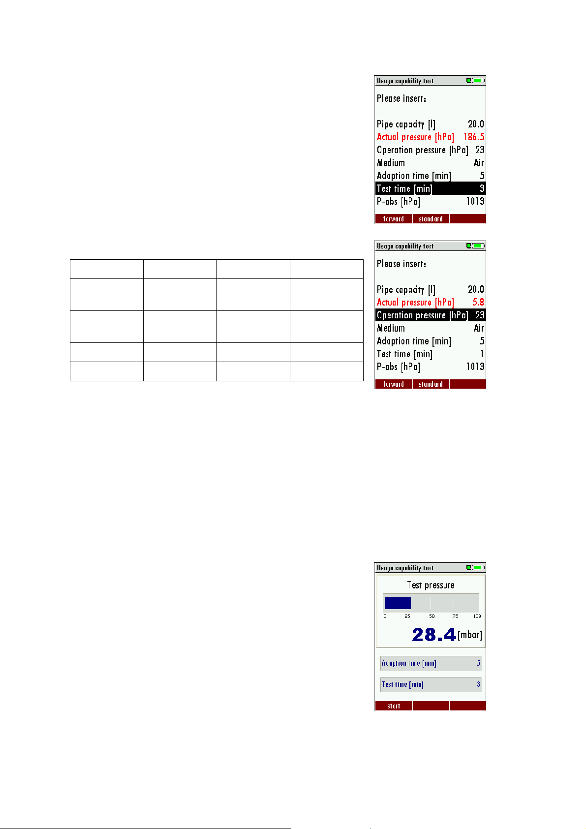
3.4.6.3 Enter pipe capacity manually
With the arrow buttons left and right the calculated pipe capacity can
be inserted. Capacity range between 3 and 1000 Liter. Default is 20
Liter.
In case the capacity is smaller than 3 Liters the calculation will be done
with 3 Liter.
3.4.6.4 Enter all other parameters
Minimal value Maximal value Standard value
Operation
pressure
Adaption
phase
Test duration 1 20 1
P-abs 800 1200 1013
When entering an operation pressure <30 mbar calculations will be
made based on the reference operation pressure 23 mbar.
When entering an operation pressure > 30 mbar calculations will be
made using the inserted operation pressure.
Medium is the gas in the pipe being used during the test. Methane and
air are available for selection. It is important to select the right medium
because Methane can evacuate more easily through a leakage than
air!
The test result is always based on Methane.
With F2 the values will be set back to the default values in the chart
above.
15 100 23
1 80 5
3.4.6.5 Apply test pressure
In this screen you will aply pressure to the pipe that will be tested. If
the pressure is below 20 mbar the pressure bar will be red and the
MFplus will display an error message when the test is started.
When using diagram 6.2 the test pressure will be applied from the
operation pressure. Therefore open the tap for a couple of seconds.
When using diagram 3.4.1 the syringe is replaced with the pump ball
with outlet valve. See diagram 3.4.3.
26
Page 27
MRU GmbH USER MANUAL MFplus Part 2 OPTION TRGI
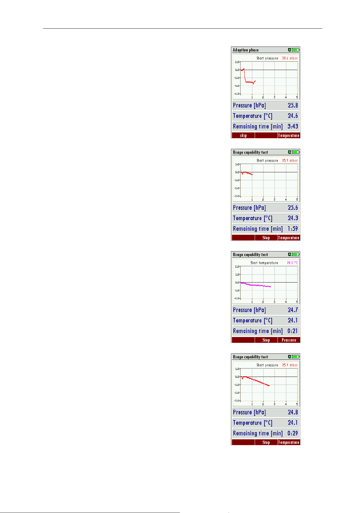
3.4.6.6 Adaption phase
The adaption phase can be shortened at any time using the F1 button.
With F3 the temperature curve will be displayed.
Once the adaption phase is completed the stress test will start
automatically.
3.4.6.7 Test phase
Now the usage capability test is in operation. Also here F3 will make
the temperature curve visible.
The temperature curve will help judging the test result. A decreasing
temperature during the test phase can result in a low pressure drop.
There is no automatic pressure/temperature compensation!
3.4.6.8 View results
At the end of the test the start pressure, end pressure and the resulting
leakage rate will be displayed.
With the F2 button the results can be saved.
With ESC you will return to the measuring menu.
27
Page 28
MRU GmbH USER MANUAL MFplus Part 2 OPTION TRGI
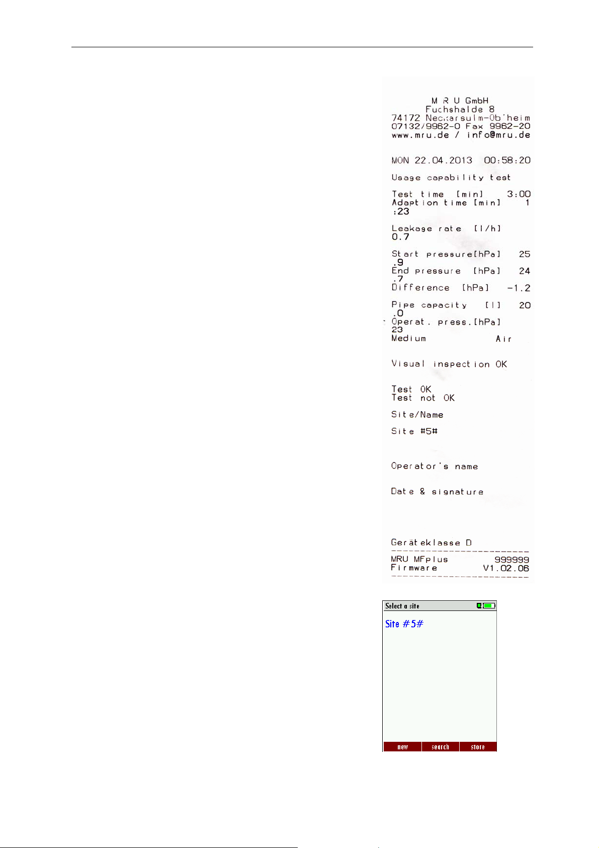
Example print-out usage capability test
3.4.6.9 Save results
Here you will select the site under which the results will be saved.
Press F3 to save the results to the site.
28
Page 29
MRU GmbH USER MANUAL MFplus Part 2 OPTION TRGI
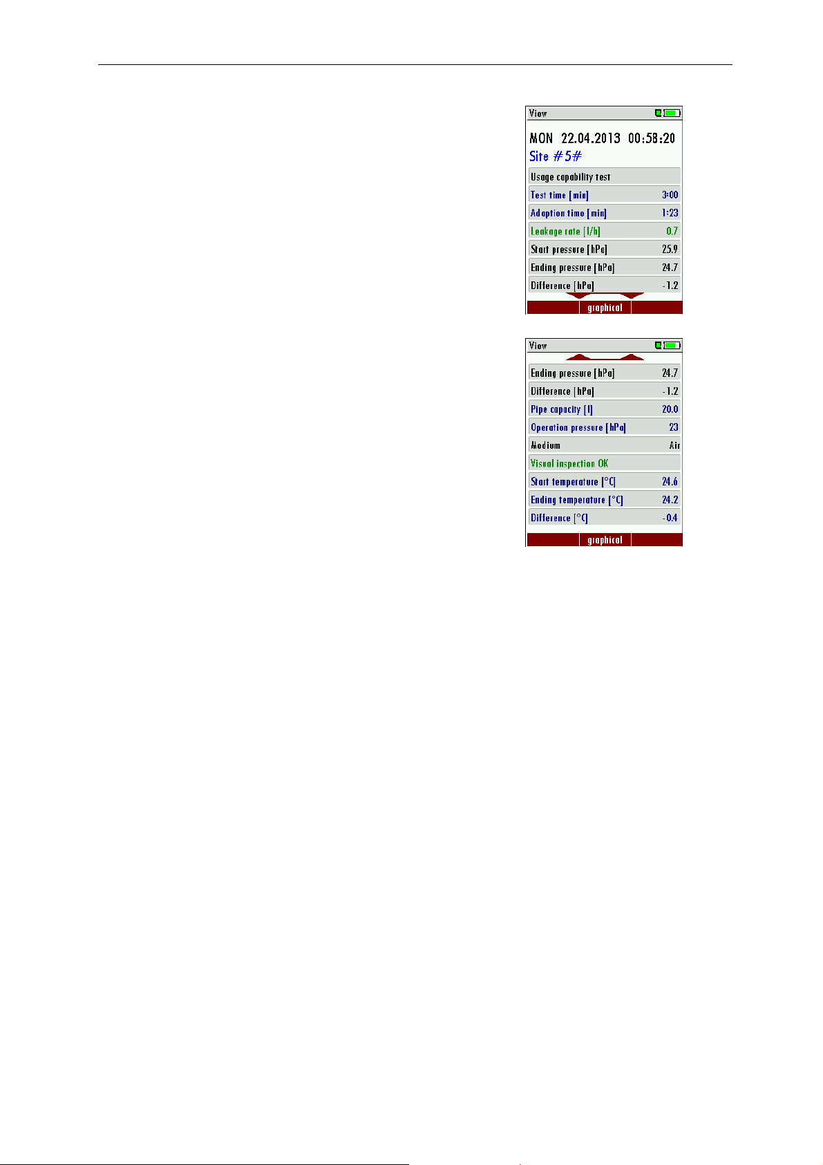
Saved results can be viewed again.
With the arrow buttons up and down additional lines can be viewed.
With ESC you will return to the measuring menu.
Additional test results.
29
Page 30
MRU GmbH USER MANUAL MFplus Part 2 OPTION TRGI
3.5 Pipe tests TRGI 50 mbar
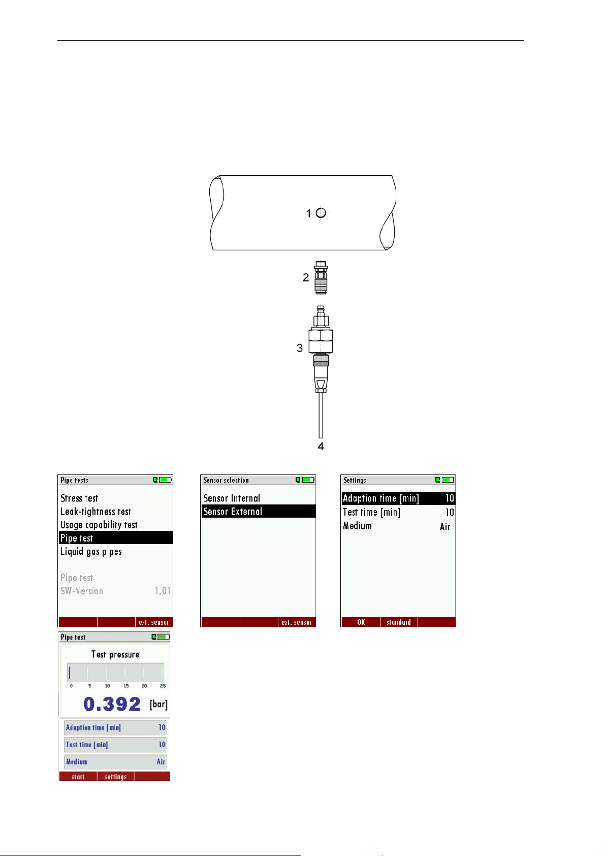
For the pipe test using medium AIR the internal pressure sensor (0 – 1,5 bar) or the external pressure sensor (0 – 5
bar, 0 – 25 bar or 0 – 40 bar) can be used.
For pipe tests using the medium WATER only the external pressure sensors may be used!
3.5.1 Connection diagram pipe test
1 – Test port
2 – 1/4“Adaptor
3 – Pressure sensor
4 – Connection cable from pressure
sensor to AUX connection at the MFplus
3.5.2 Operation
OK OK OK
30
Page 31
MRU GmbH USER MANUAL MFplus Part 2 OPTION TRGI
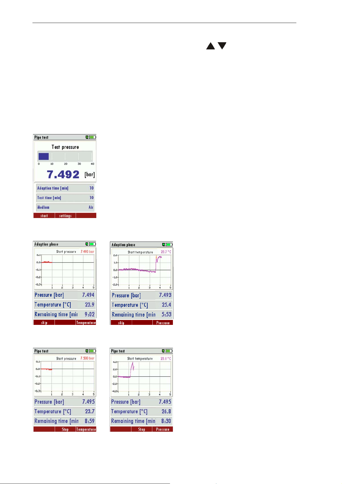
Before starting the pipe test the pressure sensor must be selected. If the expected pressure is higher than 1,5 bar or
the medium water is used, then the external sensor must be used for the test (5 bar, 25 bar or 40 bar). The
selection of the sensors and the medium is done with the arrow buttons
With F3 a zeroing can be done before starting the measurement.
When pressing Enter the medium (AIR or WATER) as well as the adaption time and duration time can be selected.
; .
ATTENTION:
The internal sensor of the MFplus may never be used for tests with water -> the
device can be flooded!!
3.5.2.1 Apply pressure
3.5.2.2 Adaption phase
3.5.2.3 Pressure test
F1 Aply the set pressure
The actual pressure, the temperature and the
remaining time is displayed. With F3-one can
switch between the temperature- and
pressure curve.
With F1 the adaption phase can be aborted.
Once the adaption time has elapsed the
measurement will start automatically.
F3
The measurement stops automatically once
the duration time has elapsed. With the
printer button the print out can be activated.
The measurement can be aborted with the
F2-button.
F3
31
Page 32
MRU GmbH USER MANUAL MFplus Part 2 OPTION TRGI
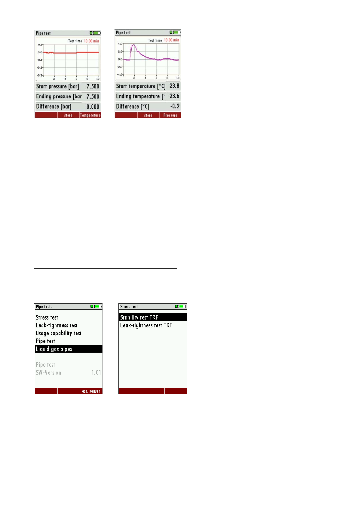
Once completed the results can be stored
with the F2-button.
F3
3.6 Liquid gas pipes (TRF)
For liquid gas pipe tests there are two tests which have to be completed: Pressure test and leak tight test.
Typical pressure ranges:
Pressure test in the range TRF 96
Pressure test in low pressure range (up to 1 bar (internal sensor)
Pressure test in medium pressure range (up to max. 2.5 bar external sensors)
Pressure test for trade and industry
Pressure test for up to max. 4 bar (vapor pipes)
Pipes in the liquid phase zone
Pressure test for up to max. 28 bar
Leak-tight test
The leak-tight test is always performed with 100 mbar.
The typical times for temperature compensation and test phase, are 10 minutes for pressure and leak-tight test.
Please be aware and observe county specific regulations!
The technical rules and regulations for liquid pipe testing are to be followed!
(Regulation - Technical Rules Liquid Gases (TRF) (Technische Regeln Flüssiggas)
3.6.1 Operation
OK
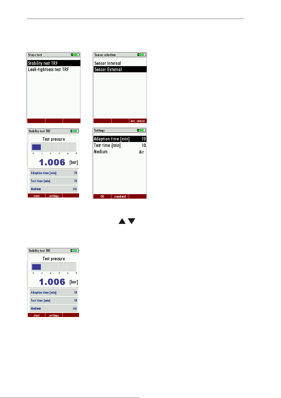
After confirmation of Liquid gas pipes – the screen Stability test TRF and Leak-tight test TRF appears.
32
Page 33
MRU GmbH USER MANUAL MFplus Part 2 OPTION TRGI
3.6.2 Stability test TRF
Before starting the pressure test the pressure sensor must be selected. If the expected pressure is higher than 1.5
bar the external pressure sensor (5 bar, 25 bar or 40 bar) must be selected!
OK OK
F2 OK
With the F2-button the medium (Air, Nitrogen or Propane) as well as the adaption- duration time can be selected.
The selection of the medium is done using the
; - buttons.
With the F2 button the default values can be restored.
3.6.2.1 Apply pressure
F1 Aply set pressure
33
Page 34
MRU GmbH USER MANUAL MFplus Part 2 OPTION TRGI
3.6.2.2 Adaption phase
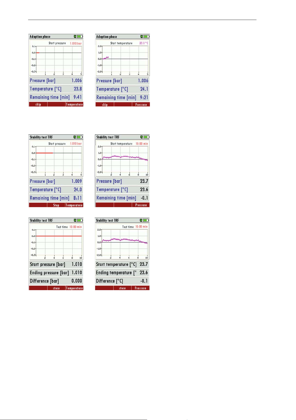
The actual pressure, the temperature and the
remaining time is displayed. With F3-one can
switch between the temperature- and
pressure curve.
With F1 the adaption phase can be aborted.
Once the adaption time is completed the
measurement starts automatically.
F3
3.6.2.3 Pressure test
The measurement stops automatically once
the duration time has elapsed. With the
printer button the print out can be activated.
The measurement can be aborted with the
F2-button.
F3
Once completed the results can be stored
with the F2-button.
F3
34
Page 35
MRU GmbH USER MANUAL MFplus Part 2 OPTION TRGI
3.6.3 Leak-tight test (TRF)
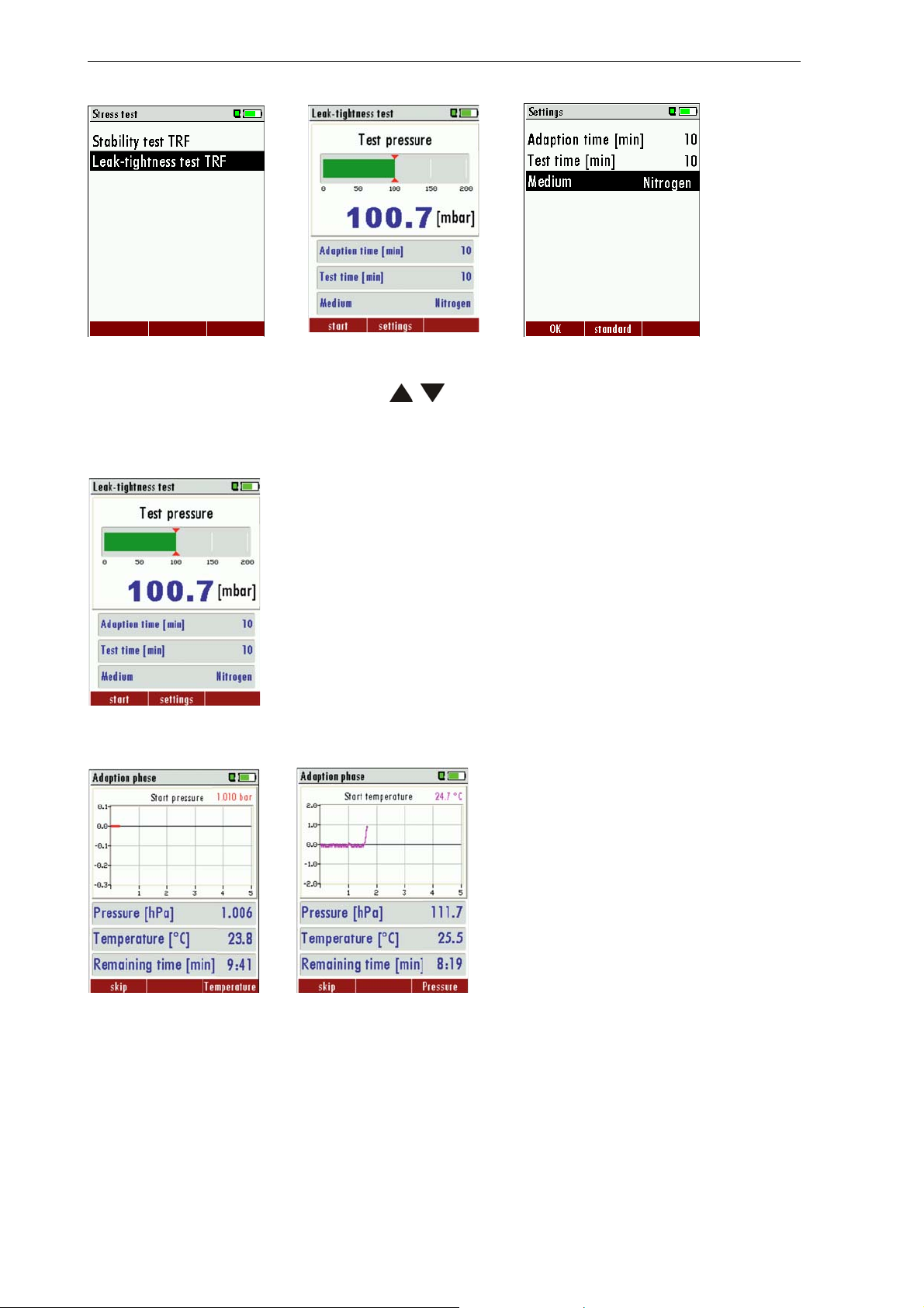
OK F2 OK
With the F2-button the medium (Air, Nitrogen or Propane) as well as the adaption- duration time can be selected.
The selection of the medium is done using the
With the F2 button the default values can be restored.
; - buttons.
3.6.3.1 Apply pressure
3.6.3.2 Adaption phase
F1 Aply set pressure
The actual pressure, the temperature and the
remaining time is displayed. With F3-one can
switch between the temperature- and
pressure curve.
With F1 the adaption phase can be aborted.
Once the adaption time is completed the
measurement starts automatically.
F3
35
Page 36
MRU GmbH USER MANUAL MFplus Part 2 OPTION TRGI
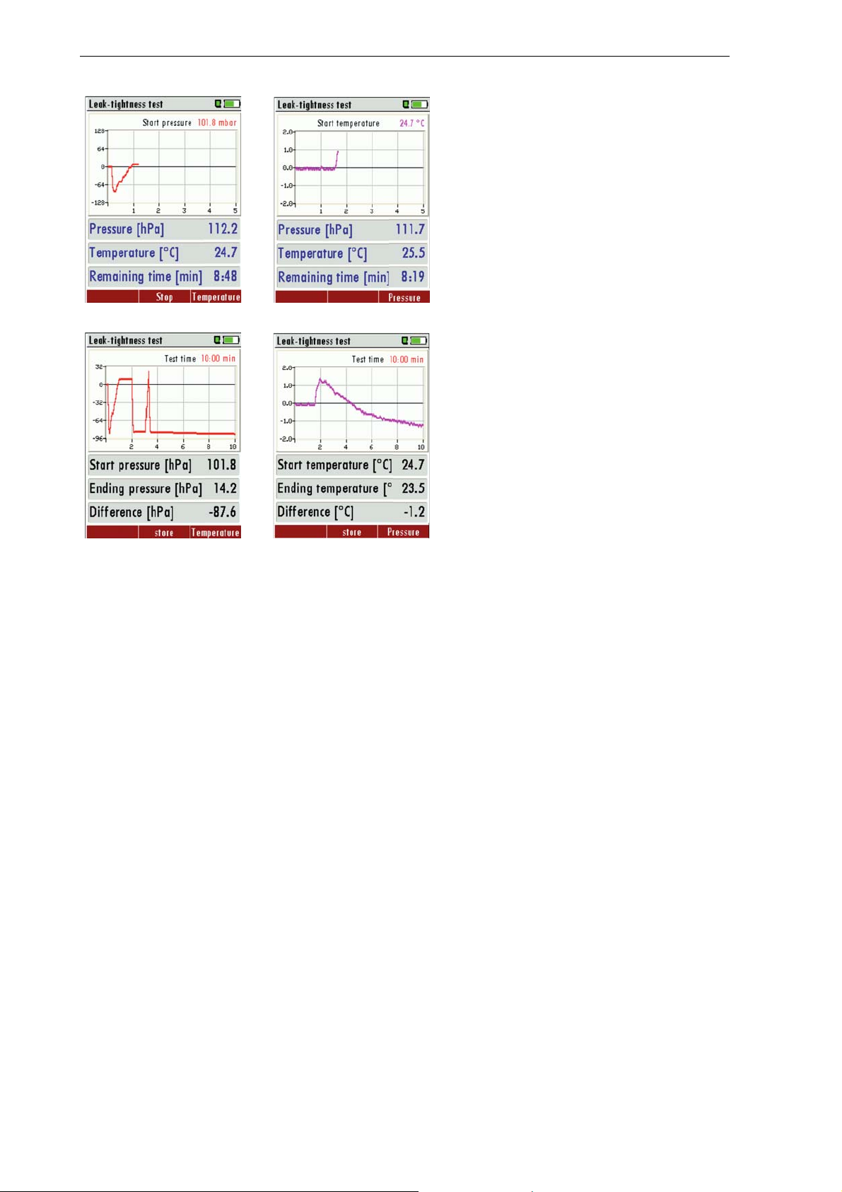
3.6.3.3 Pressure test
The measurement stops automatically once
the duration time has elapsed. With the
printer button the print out can be activated.
The measurement can be aborted with the
F2-button.
F3
F3
Once completed the results can be stored
with the F2-button.
36
Page 37
MRU GmbH USER MANUAL MFplus Part 2 OPTION TRGI
4 Accessories
4.1 Measuring accessory- Set 1, for ONE pipe gas meter # 61500
# 59072 Test pump for stress test
# 59071 Pump ball with outlet valve and balancing ball in net
# 59074 Y-Divider with tap and hose
# 59076 Hose from device to divider
# 59101 Test cap DN 25 (2“) brass for PRE- and leak-tight test - nipple NW 5
# 61499 Syringe 100 ml for capacity determination
# 50482 0,5 m transparenter silicone hose 6 x 2 mm (2 x)
# 59038 Push on connector NW 5 with 6 mm nipple brass nickel plated (2 x)
4.2 Measuring accessory- Set 2, for TWO pipe gas meter # 61501
# 59072 Test pump for stress test
# 59071 Pump ball with outlet valve and balancing ball in net
# 59074 Y-Divider with tap and hose
# 59076 Hose from device to divider
# 59148 Test plug cylindrical with tap and push on connector NW 5
# 59320 Y-Divider without tap
# 61499 Syringe 100 ml for capacity determination
# 50482 0,5 m transparenter silicone hose 6 x 2 mm (2 x)
# 59038 Push on connector NW 5 with 6 mm nipple brass nickel plated (2 x)
4.3 Connection set SMALL only for usage capability test # 64072
# 59047 Mini tap
# 59046 Hose grommet 6 mm
# 63832 Hose grommet 6 mm
# 50482 Silicone hose 6x2 transparent, 1.8 m
# 54088 T-Divider
# 53420 Driller
# 61499 Syringe 100 ml
4.4 Additional accessory
# 64322
37
Black box for full automatic pipe capacity determination*
To be connected to the AUX port of the MFplus with 3 m cable and hose.
Measuring accessory - Set 1 or 2 additional needed
Page 38

MRU GmbH USER MANUAL MFplus Part 2 OPTION TRGI
# 61544 PC-Software DMWin for administration of measuring results incl. Protocol printer and data
transfer cable
# 62693 IR thermal printer
#62998 Protective cover with magnets for printer
# 59465 Printer paper (5 rolls)
# 59702 Test pump for pressures > 500 mbar
# 59071 Pump ball for pressures < 500 mbar
# 59704 Y-Divider with tap and hose (needed for 1 and 2 pipe connections (gas meter))
# 59320 Y-Divider without tap (additional needed for 1 pipe connections (gas meter))
# 59076 Pressure hose for connection between MFplus and Y-Divider
# 59054 Test plug, tapered with tap and push on connection (¾“ up to 1 ¼“)
# 59174 Test plug, cylindrical with tap and push on connection (¾“)
# 59148 Test plug, cylindrical with tap and push on connection (1“)
# 59149 Test plug, cylindrical with tap and push on connection (1 ¼“)
# 59326 Thread adaptor 1/8“, tap and push on connector
# 59722 Thread adaptor ¾“ tap and push on connector
# 59723 Thread adaptor 1“, tap and push on connector
# 59724 Thread adaptor 1 ¼“, tap and push on connector
# 59101 Test cap with 1 connection, R2“ (DN25) for PRE- and Leak-tight test
# 61499 Syringe for capacity determination
# 61504 Robust ABS transport case for device and accessories
# 58945 Pressure sensor external < 25 bar, incl. Adaptor ¼“ with push on connector SW 5
# 58944 Attatching temperature sensor
# 59173 Adaptor ¼“ with quick connector NW5 for external pressure sensor
# 59387 Test adaptor
4.5 Optionen
# 59304 Double push on connector NW 5
#63684 External pressure sensor 5 bar
# 63685 External pressure sensor 25 bar
# 63686 External pressure sensor 40 bar
38
Page 39

MRU GmbH USER MANUAL MFplus Part 2 OPTION TRGI
5 Technical details MFplus Option TRGI
5.1 Sensor specifications pressure measurement
Measuring range 0 – 1.500 mbar Over-load 2 bar
Accuracy ± 0,5 mbar or ± 3 % of the measuring value – whichever is larger
External pressure sensor 5 bar
Measuring range 0 – 5 bar Over-load 10 bar
Accuracy ± 0,02 bar or ± 1 % of the measuring value – whichever is larger
External pressure sensor 25 bar
Measuring range 0 – 25 bar Over-load 50 bar
Accuracy ± 0,1 bar or ± 1 % of the measuring value – whichever is larger
External pressure sensor 40 bar
Measuring range 0 – 40 bar Over-load 80 bar
Accuracy ± 0,2 bar or ± 1 % of the measuring value – whichever is larger
5.2 Calculated value gas leakage rate
Measuring range 0 – 8,00 l/h 0,1 l/h resolution
Accuracy ± 0,2 l/h or ± 5 % of the measuring value – whichever is larger
5.3 Additional specifications
Maximal testable pipe capacity 250 l
Operation time with fully charged battery ca. 35 h (in pressure measuring mode without running pump)
Ambient air pressure 860 – 1080 mbar
Measuring medium not aggressive gases
Technical changes subject to
modifications! Date released: 29.11.2011
Page 40

MRU GmbH USER MANUAL MFplus Part 2 OPTION TRGI
6 Usage capability test
6.1 What is a Usage capability test
The Usage capability test helps to determine and judge leakages (gas leakage) in low pressure gas pipes.
Tested will be all in operation or repaired pipes with all faucets, however without gas units and their
regulators and security devices. The gas meter can be included in this test (using backward test).
The usage capability test my not be performed when:
- New installed pipes (= pipes within warranty)
- Pipes that had a limited usage capability or a NO usage capability and had been repaired to be used
- Not in use pipes which want to be used again
- Pipes in middle- and high pressure range.
Test medium: Air or Methane
Test pressure: 23 mbar according to DVGW worksheet G600.
Unlimited usage capability: > 0 l/h to < 1,0 l/h
The pipe can be used for unlimited time without repair.
Limited usage capability: >1,0 l/h bis < 5,0 l/h
The pipe may be used for a maximum of 4 weeks. Within these 4 weeks the pipe must be repaired to achieve
Unlimited Usage Capacity again (Leak-tight test).
NO usage capability: > 5,0 l/h
The use of this pipe must be stopped immediately. Take action to determine the defect.
Important is the technical security judgement:
Also a leak tight gas pipe can have limited or no usage capability. The physical condition must be considered
as well!
Once you smell gas the system is leaking. The above mentioned usage capability gradings do not apply.
On the following pages different connection possibilities are shown.
40
Page 41
MRU GmbH USER MANUAL MFplus Part 2 OPTION TRGI
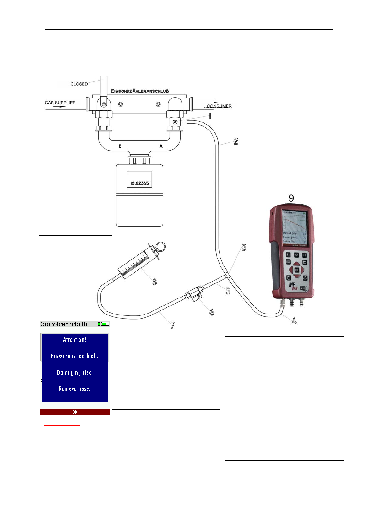
6.2 Connection diagram Usage capability test without dismounting gas meter using SET #64072
(small)
108 ml =
Syringe not pulled
6.2.1
6.2.2
ATTENTION:
Pull out the syringe piston slowly to avoid
pressures above 50 mbar (MFplus).
The pressure can easily exceed 100
hPa when using the syringe to
determine the pipe capacity.
1 # 59387 Test plus
2 # 50482 Silicone hose 6x2
3 # 59074 T-connector 3x6 mm
4 # 50482 Silicone hose 6x2
5 # 50482 Silicone hose 6x2
6 # 59047 Mini tap
7 # 50482 Silicone hose 6x2
8 # 61499 Syringe 108 ml
plus
9 MF
41
Page 42
MRU GmbH USER MANUAL MFplus Part 2 OPTION TRGI
6.3 Operation
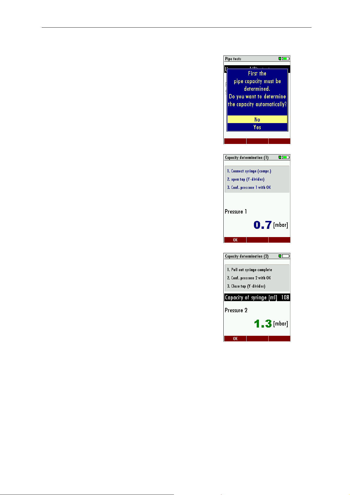
To be able to calculate the leakage rate first the pipe capacity must be
determined.
In the first screen of the usage capability test you are asked if you want
to determine the pipe capacity automatically. As alternative you can
insert the pipe capacity manually.
No – continue with 6.3.2 Enter pipe capacity manually
6.3.1 Automatic capacity determination
The capacity determination using the syringe is performed by extracting
a defined capacity (syringe) from the closed pipe system. From the
resulting pressure drop the MFplus calculates the pipe capacity.
Please follow the instructions on the display.
When testing big capacity pipes (>200 Liter) one syringe capacity is not
enough to get enough pressure drop. This will be displayed in a red
pressure value on your screen.
In this case you can raise the syringe volume value using the RIGHT
arrow button and then take additional volume using the syringe.
Continue with enter all additional parameters
42
Page 43
MRU GmbH USER MANUAL MFplus Part 2 OPTION TRGI
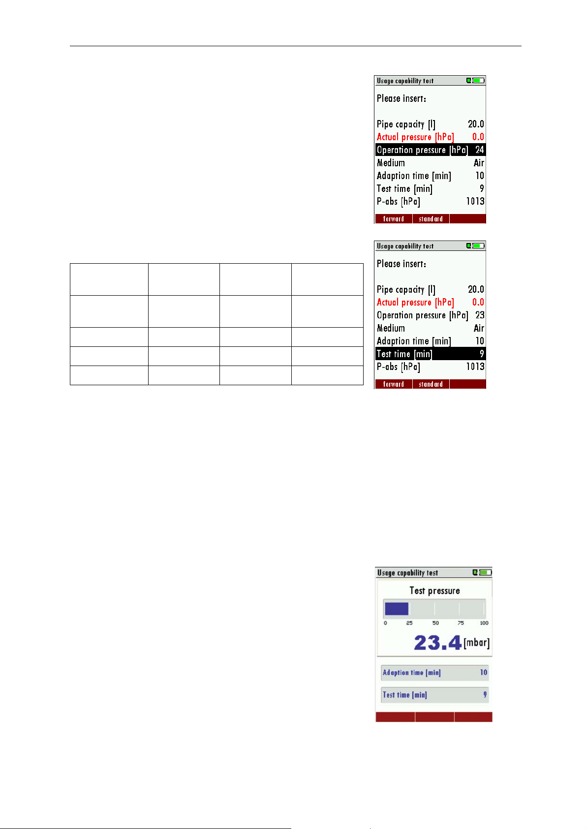
6.3.2 Enter pipe capacity manually
With the arrow buttons left and right the calculated pipe capacity can
be inserted. Capacity range between 3 and 1000 Liter. Default is 20
Liter.
In case the capacity is smaller than 3 Liters the calculation will be done
with 3 Liter.
6.3.3 Enter all other parameters
Minimal value Maximal value Standard
value
Operation
pressure
Adaption phase 1 80 5
Test duration 1 20 1
P-abs 800 1200 1013
When entering an operation pressure <30 mbar calculations will be
made based on the reference operation pressure 23 mbar.
When entering an operation pressure > 30 mbar calculations will be
made using the inserted operation pressure.
Medium is the gas in the pipe being used during the test. Methane and
air are available for selection. It is important to select the right medium
because Methane can evacuate more easily through a leakage than
air!
The test result is always based on Methane.
With F2 the values will be set back to the default values in the chart
above.
6.3.4 Apply test pressure
15 100 23
In this screen you will apply pressure to the pipe that will be tested. If
the pressure is below 20 mbar the pressure bar will be red and the
MFplus will display an error message when the test is started.
43
Page 44
MRU GmbH USER MANUAL MFplus Part 2 OPTION TRGI
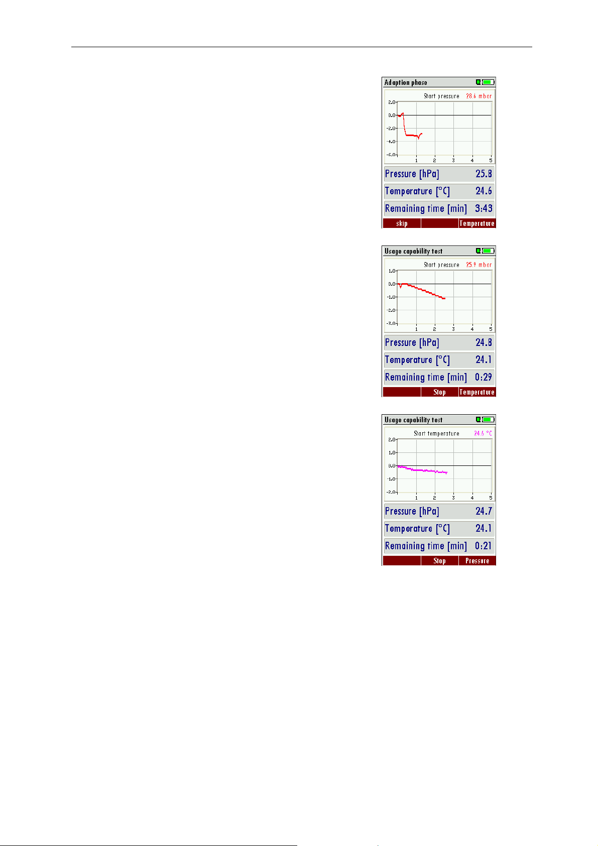
6.3.5 Adaption phase
The adaption phase can be shortened at any time using the F1 button.
With F3 the temperature curve will be displayed.
Once the adaption phase is completed the stress test will start
automatically.
6.3.6 Test phase
Now the usage capability test is in operation. Also here F3 will make
the temperature curve visible.
The temperature curve will help judging the test result. A decreasing
temperature during the test phase can result in a low pressure drop.
There is no automatic pressure/temperature compensation!
44
Page 45
MRU GmbH USER MANUAL MFplus Part 2 OPTION TRGI
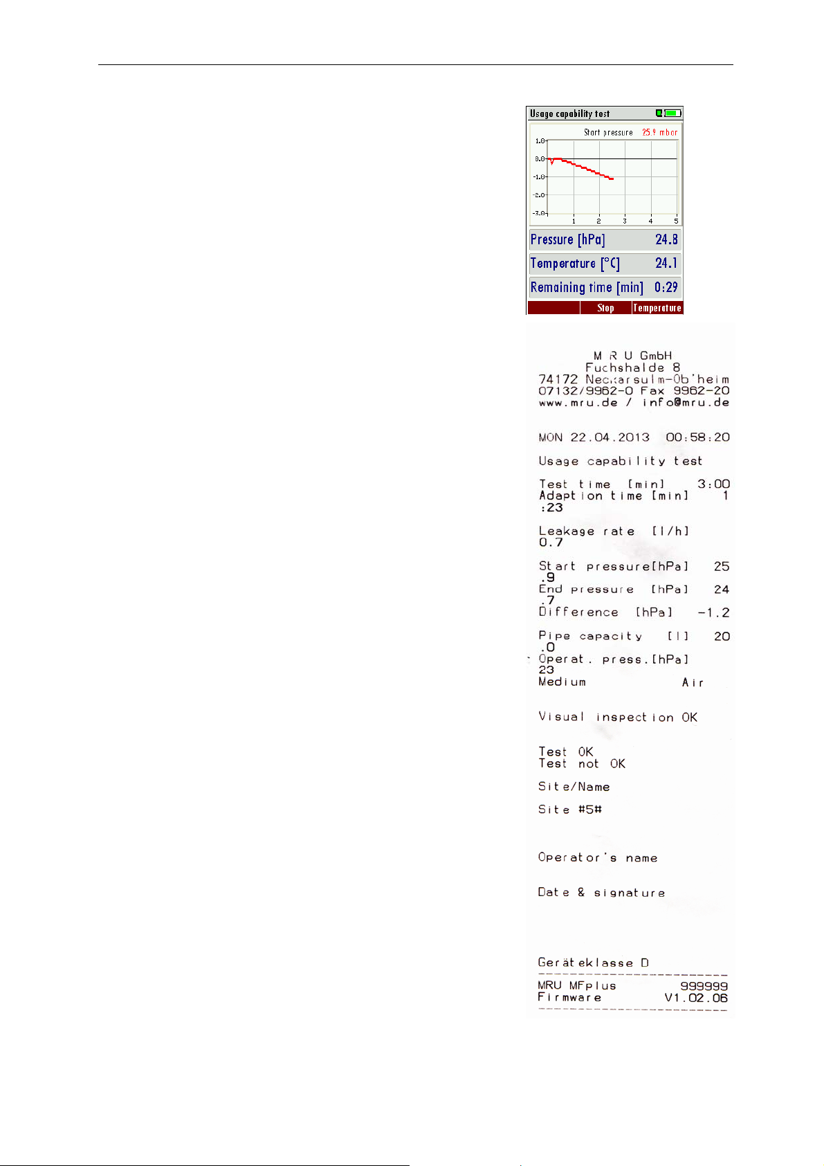
6.3.7 View results
At the end of the test the start pressure, end pressure and the resulting
leakage rate will be displayed.
With the F2 button the results can be saved.
With ESC you will return to the measuring menu.
Example print-out usage capability test
45
Page 46
MRU GmbH USER MANUAL MFplus Part 2 OPTION TRGI
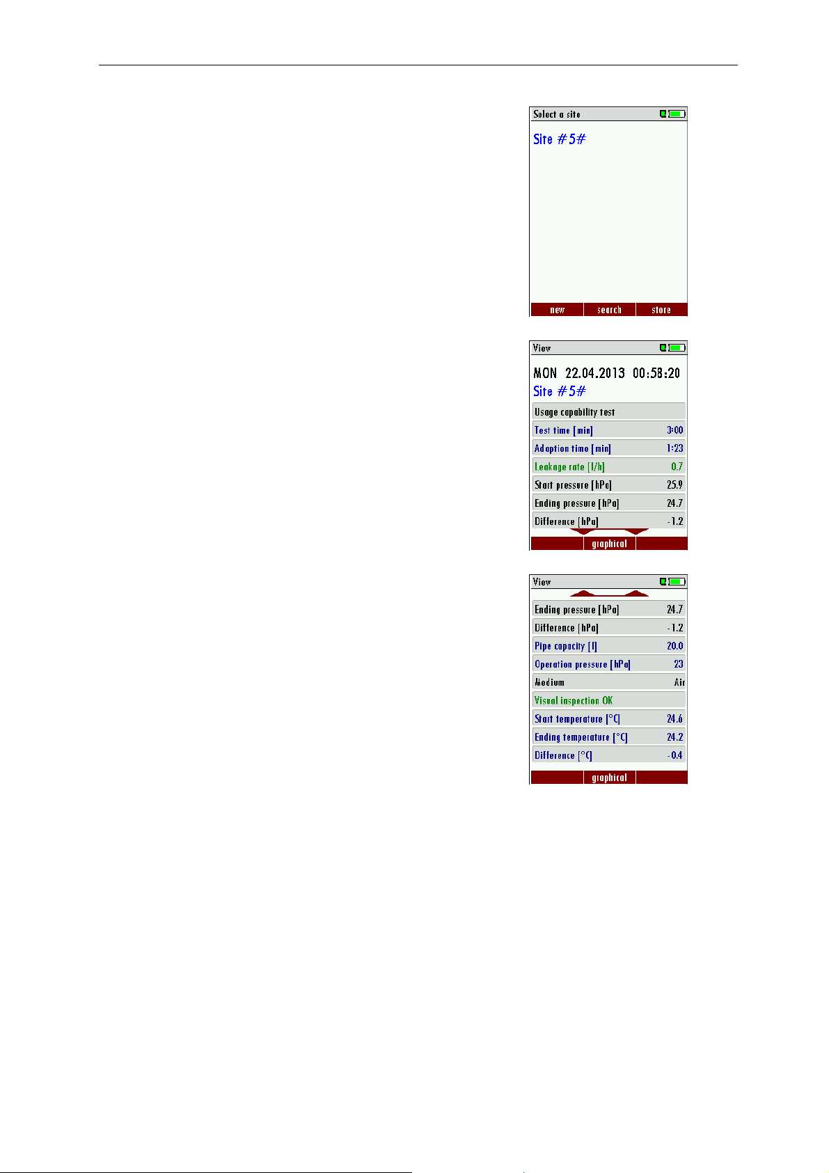
6.3.8 Save results
Here you will select the site under which the results will be saved.
Press F3 to save the results to the site.
Saved results can be viewed again.
With the arrow buttons up and down additional lines can be viewed.
With ESC you will return to the measuring menu.
Additional test results.
46
Page 47

MRU GmbH USER MANUAL MFplus Part 2 OPTION TRGI
Technical data change w/o notice! Date of issue: 20130430
47
 Loading...