

Page 1
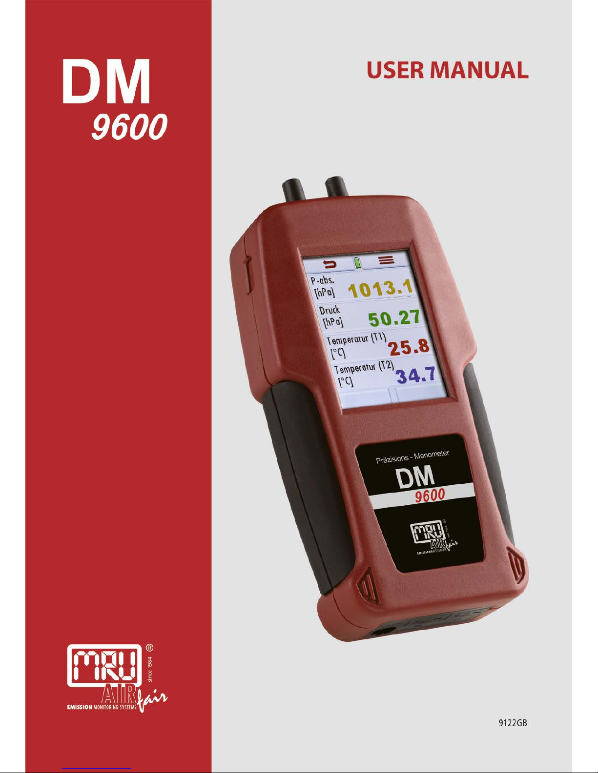
USER MANUAL DM9600
MRU GmbH, D-74172 Neckarsulm
1 / 39
Page 2
USER MANUAL DM9600
MRU GmbH, D-74172 Neckarsulm
2 / 39
Page 3

USER MANUAL DM9600
MRU GmbH, D-74172 Neckarsulm
3 / 39
Content
1. General information ............................................................................................................ 6
1.1. The company MRU GmbH ......................................................................................... 6
1.2. Important notes for this operating manual .................................................................. 7
1.3. Intended usage .......................................................................................................... 7
1.4. Security direction ....................................................................................................... 7
1.5. Packaging .................................................................................................................. 8
1.6. Return of hazardous waste - Waste Disposal/Returns/Warranty ............................... 8
1.7. Return of analyzer according to ElektroG .................................................................. 8
2. DM9600 description ............................................................................................................ 9
2.1. Introduction ................................................................................................................ 9
2.2. The DM9600 .............................................................................................................. 9
3. Operating the DM9600 ..................................................................................................... 10
3.1. Power on and power off ........................................................................................... 10
3.2. Zeroing ..................................................................................................................... 10
3.3. Function keys ........................................................................................................... 10
3.4. Context menu ........................................................................................................... 10
3.5. Display ..................................................................................................................... 11
3.6. Menu structure ......................................................................................................... 11
4. First startup ....................................................................................................................... 13
4.1. Readiness of the DM9600........................................................................................ 13
4.2. Equipment settings .................................................................................................. 13
4.3. Adjusting date and time ........................................................................................... 14
4.4. Bluetooth settings (optional)..................................................................................... 14
5. Maintenance and care ...................................................................................................... 15
5.1. Cleaning and care .................................................................................................... 15
6. Preparation for each measurement .................................................................................. 16
6.1. Power supply ........................................................................................................... 16
6.2. Automatic Auto-off function ...................................................................................... 16
6.3. Measuring with grid power supply / Battery charging ............................................... 16
6.4. Battery charge condition .......................................................................................... 16
6.5. Operating temperature ............................................................................................. 16
6.6. Power up and zeroing .............................................................................................. 16
7. Performing a measurement .............................................................................................. 17
7.1. Auto-Log function ..................................................................................................... 17
7.2. General measurement ............................................................................................. 18
7.3. Pressure measurement ............................................................................................ 19
7.4. Temperature measurement...................................................................................... 20
7.5. Flow velocity measurement (option) ........................................................................ 21
7.6. Leak detection using the external HC-Probe (option) .............................................. 23
7.7. Usage capability test (option) ................................................................................... 24
7.8. Printing measurement results .................................................................................. 27
8. Data storage ..................................................................................................................... 28
8.1. Data storage structure ............................................................................................. 28
8.2. Measurements in the data storage menu ................................................................. 28
8.3. Sites ......................................................................................................................... 29
8.4. Data transfer using the SD-Card .............................................................................. 30
8.5. Information about the data storage .......................................................................... 31
Page 4

USER MANUAL DM9600
MRU GmbH, D-74172 Neckarsulm
4 / 39
9. EXTRAS / Settings ........................................................................................................... 32
9.1. Service adjustment menu ........................................................................................ 32
9.2. Factory settings........................................................................................................ 32
9.3. Service values.......................................................................................................... 32
10. Appendix ...................................................................................................................... 33
10.1. Technical details ...................................................................................................... 33
10.2. Firmware update ...................................................................................................... 36
10.3. Trouble shooting ...................................................................................................... 37
10.4. Declaration of conformity DM9600 ........................................................................... 38
Page 5

USER MANUAL DM9600
MRU GmbH, D-74172 Neckarsulm
5 / 39
Inspect Shipment for Damage
Carefully inspect the entire shipment for damage in the presence of the shipper’s agent,
removing packaging material if necessary. Note any damage to packaging and/or goods on
Packing List and have it signed by the shipper’s agent prior to accepting the shipment. Submit
damage claim to MRU immediately.
NOTE: Damage claims not received by MRU within 3 days of receipt of shipment will not be
accepted.
Important notice!
This high quality electronic device utilizes batteries that discharge even when the device is not
in use. Therefore, it is very important to charge the batteries every 6 months, even if the device
is not in use.
Failing to follow these instructions will void your warranty!
Save the original box and the packing material for use if the device must be shipped in the
future.
The products described in this manual are subject to continuous development and improvement
and it is therefore acknowledged that this manual may contain errors or omissions. MRU
encourages customer feedback and welcomes any comments or suggestions relating to the
product or documentation.
Please forward all comments or suggestions to the Customer Feedback Department at the
following address:
MRU GmbH
Fuchshalde 8 + 12
74172 Neckarsulm / Obereisesheim
GERMANY
Phone +49 71 32 99 62 0 (Switch board)
Phone +49 71 32 99 62 61 (Service)
Fax +49 71 32 99 62 20
Email: [email protected]
Homepage: www.mru.eu
This manual is intended solely as a guide to the use of the product.
MRU shall not be liable for any loss or damage whatsoever arising from content errors or
misinterpretation of information’s from this manual or any miss-use resulting from the use of this
manual.
Page 6
USER MANUAL DM9600
MRU GmbH, D-74172 Neckarsulm
6 / 39
1. General information
1.1. The company MRU GmbH
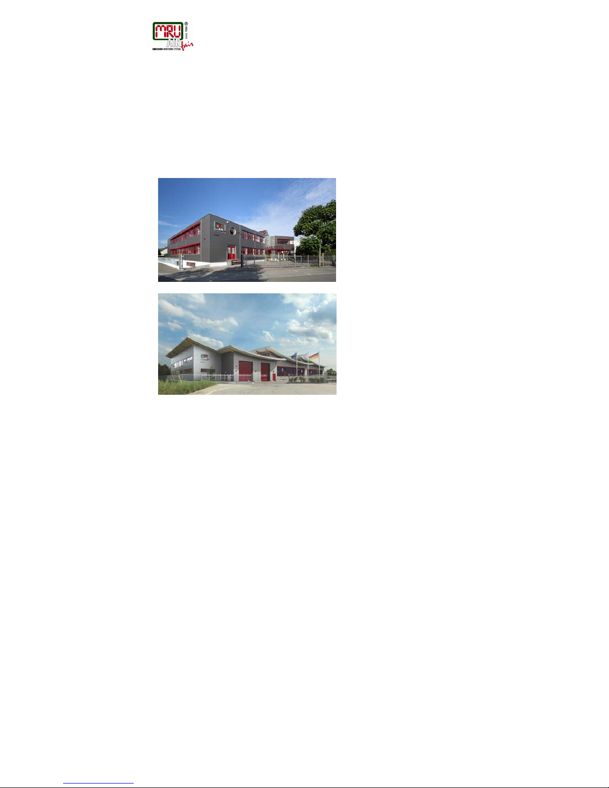
This device, DM9600 is manufactured by the MRU GmbH in Neckarsulm Germany (founded in
1984), a medium sized company that specializes in developing, producing and marketing high
quality emission monitoring analyzers. MRU GmbH produces a wide range of instruments, from
standard analyzers up to tailor made industrial analyzers. MRU GmbH contact details are listed
on the previous page.
Plant 1: Sales, Service, R&D and
administration
Plant 2: Production
Page 7
USER MANUAL DM9600
MRU GmbH, D-74172 Neckarsulm
7 / 39
1.2. Important notes for this operating manual
The operating manual is an important part of your delivery. It explains the usage and purpose of
this device and ensures the safety of the user and the environment.
Every user has the obligation to read the complete manual and getting familiar with the device
and follows all directions, especially those regarding safety.
Additional hints in other chapters will be clearly marked with an ATTENTION sign.
1.3. Intended usage
The DM9600 is a manometer that is used for pressure measurements as well as temperature
measurement of NON-explosive gases.
1.4. Se curity direction
The following security directions must be followed at any time.
They are essential and indispensable element of this manual.
Failing to follow these instructions will void your warranty!
Security directions
The DM9600 may only be used for its intended purpose.
Our analyzers are checked according to the following regulations:
VDE 0411 (EN61010) and DIN VDE 0701 before they leave the MRU GmbH factory.
MRU technical products are designed and manufactured according to DIN 31000/ VDE 1000
and UVV = VBG 4 of the professional guilds for fine mechanics and electrical engineering.
MRU GmbH assures that the analyzer complies to the essential requirements of the legal
regulations of the member states of the electro-magnetic compatibility (89/336/EWG).
Specific security directions
Only use a suitable USB battery charger 5V/>0,7A
Metal parts and accessories may not be used as electric conductors.
The device may not be used under water.
The device may not be stored near fire or great heat.
The temperature range of the temperature sensors may not exceed their nominal ranges, this
can destroy these sensors.
The measured pressure may not exceed the measuring range of the device.
Electronic devices will be damaged when dropped.
Page 8
USER MANUAL DM9600
MRU GmbH, D-74172 Neckarsulm
8 / 39
User directions for Li-Ion batteries
• The end-user has NO access to the internal battery.
• This rechargeable battery may only be used in the DM9600.
• Never throw the battery into fire.
Don’t charge the battery at high temperatures
Don’t store the battery in a hot location
• Don’t deform the battery, don’t short circuit or change the battery in any form!
• The battery may not be used in or under water.
• Don’t stress the battery with high mechanical strain and don’t throw the
battery.
• Don’t squeeze nor cut off the battery wires!
• Don’t store nor carry the battery with any sharp items
• Don’t connect the (+) contact with the (-) contact or contact with metal.
• Not following the above-mentioned directions may cause heat, fire and
explosion.
• The life span of this battery is about 500 charging and dis charging cycles.
With increasing charging cycles the specified device running time will decrease with each
charging cycle
1.5. Packaging
Packing regulation of 12.07.1991
If your local waste facility does not except MRU packing materials for disposal, you may
return it to MRU or our local sales representative. Packing materials returned to MRU must
be returned prepaid.
1.6. Return of haz ardous waste - Waste Disposal/Returns/Warranty
MRU GmbH is required to accept the return of hazardous waste such as batteries that cannot
be disposed of locally. Hazardous waste must be returned to MRU prepaid.
1.7. Return of analyzer according to ElektroG
MRU GmbH is required to accept the return, for proper disposal, of all analyzers delivered after
13th of August 2005. Analyzers must be returned to MRU prepaid.
Page 9
USER MANUAL DM9600
MRU GmbH, D-74172 Neckarsulm
9 / 39
2. DM9600 description
2.1. Introduction
The main task of the DM9600 is measuring pressure and temperature.
Optional with AUX port:
HC-probe for gas leak detection
External pressure sensor to measure higher pressures
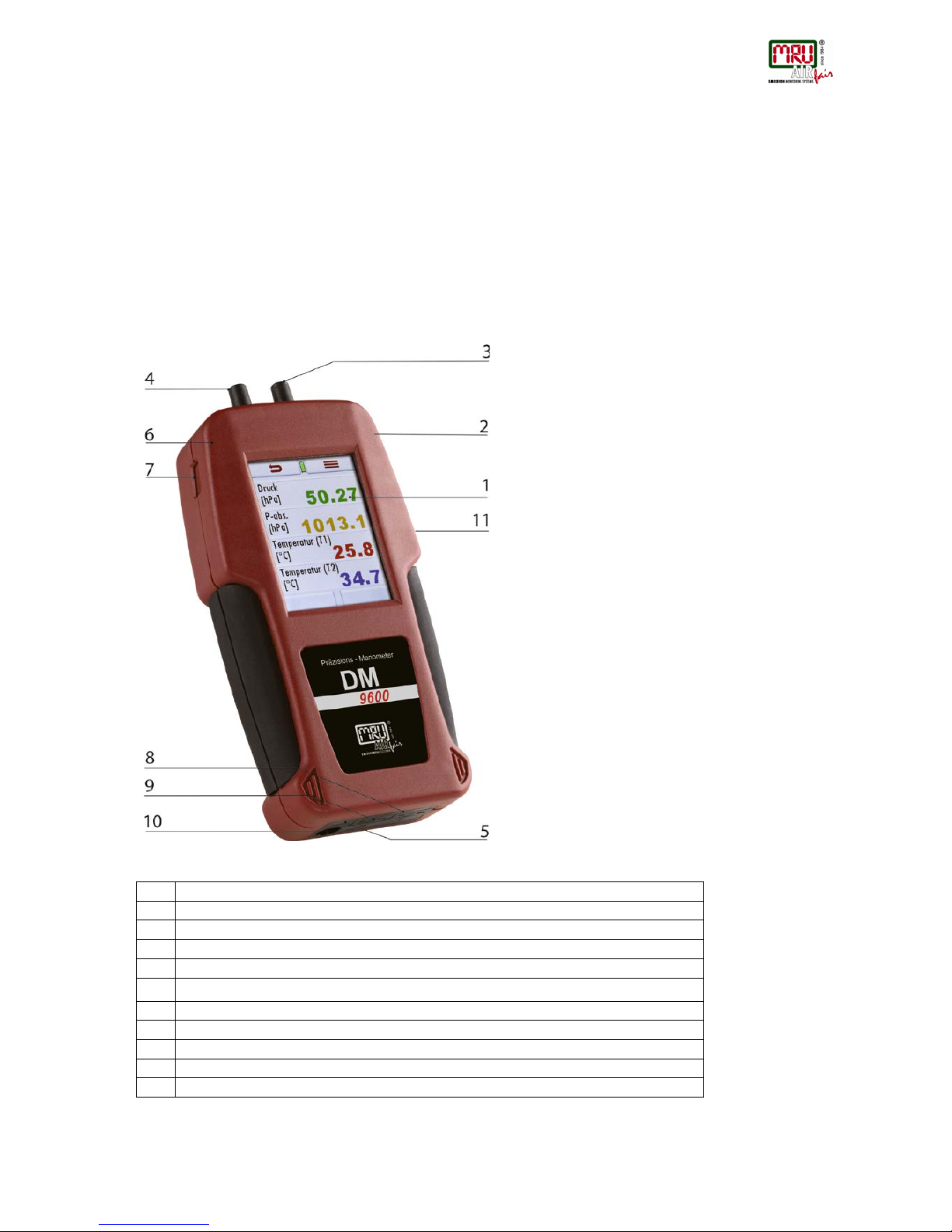
2.2. The DM9600
The DM9600 has a compact and robust fiber-reinforced plastic enclosure.
It is entirely operated using the color touch screen.
1
Touch screen
2
Mini USB interface for data transfer and battery charging
3
Pressure port P1
4
Pressure port P2
5
IR interface for external IR Printer
6
Rear magnets for hands free operation
7
Micro-SD-card reader
8
Temperature port Temp 1
9
Temperature port Temp 2
10
AUX-port
11
Reset-button (on the rear side)
Page 10
USER MANUAL DM9600
MRU GmbH, D-74172 Neckarsulm
10 / 39
3. Operating the DM9600
3.1. Power on and power off
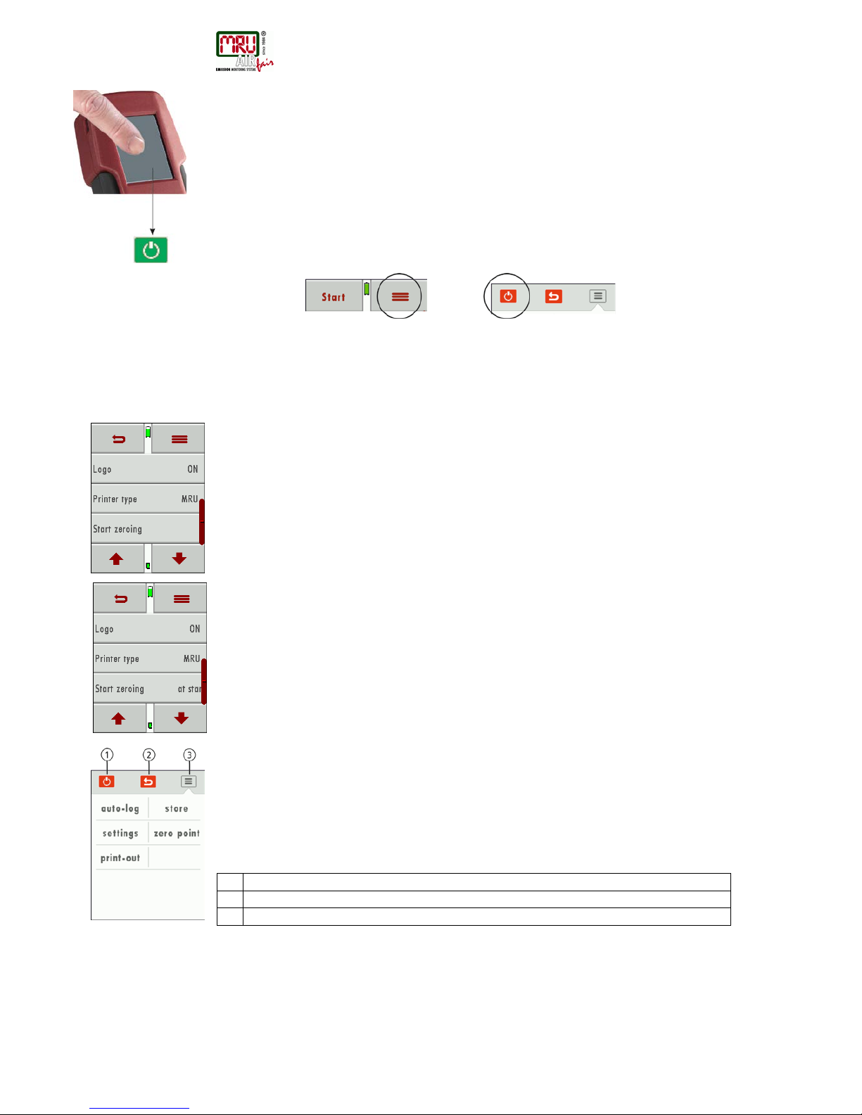
The DM9600 is powered up using the touch screen.
Touch the blank screen, then press the appearing green ON button.
The display will turn dark again if the green ON button is not pressed within 5 seconds.
You will use the context menu button to power the unit down.
Press the context button then the appearing OFF button.
3.2. Zeroing
The zeroing is selectable between last zeroing and
zeroing during start up
Last zeroing:
The unit will select the last zeroing of the pressure sensor.
Using this mode might have inaccurate measurement results due to temperature influences
(zero drift) and the unit will not ask to perform zeroing during start up.
Zeroing during start up:
The user will be asked to perform a zeroing when this mode is selected.
The measurement accuracy is warranted once the zeroing was performed. The DM9600 will
select last zeroing in case the zeroing was not performed -> see last zeroing.
3.3. Function keys
Pre-defined function keys will appear on the upper and lower screen border – these keys will
differ depending on the screen content.
The upper border typically displays the return and context buttons.
The lower border often displays the up and down buttons.
There can be additional or other buttons, depending which program or menu currently is used.
3.4. Context menu
The context menu button is an addition to the function keys. All available possibilities for the
current displayed screen will be available for selection.
Some of the available functions are: “power down the unit”, “exit window”, “close context menu
without action” (just to name a few).
1
power down the unit
2
exit window
3
close context menu without action
Page 11
USER MANUAL DM9600
MRU GmbH, D-74172 Neckarsulm
11 / 39
3.5. Display
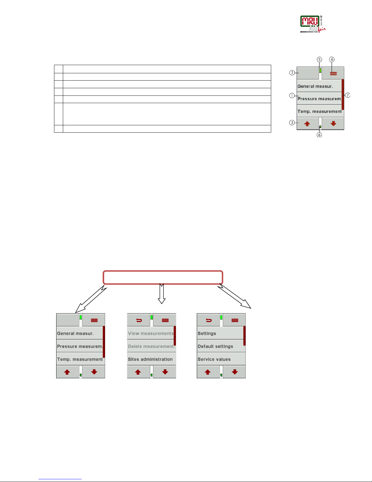
All information needed to operate the DM9600 will be displayed as follows:
3.6. Menu structure
The DM9600 has 3 available main menus:
Measurement, Storage and Extras.
The context menu key lets you select the available main menus.
• Menu measurement: All available measurement options will be displayed
and can be selected here.
This screen will only display installed and available
options.
• Menu Storage: All available storage options will be displayed here.
• Menu Extras: All other options are displayed here, for example
setting to adapt your DM9600.
See chapter 7 for
measurement menu.
See chapter 8 for
Storage menu.
See chapter 9 for
Extras menu.
1
Main menu
2
Function keys
3
Function keys
4
Context key
5
Battery charging condition (Lithium-Ion Battery)
6
SD-Carte inserted SD-Card reader
GREEN symbol – read and write is possible
YELLOW symbol – read only
7
Scroll bar indicator for the main menu
DM9600
Page 12

Page 13
USER MANUAL DM9600
MRU GmbH, D-74172 Neckarsulm
13 / 39
4. First startup
The DM9600 can be customized during the first start-up. Of course, all modifications can be
also done at a later stage.
4.1. Readiness of the DM9600
• Unpack the DM9600, read the complete manual.
• The DM9600 is delivered fully assembled and ready to use. Nevertheless,
check if the delivery is complete and that nothing is damaged.
• Recommendation: Charge the battery for 5 hours.
• Check date and time / modify if needed.
4.2. Equipm ent settings
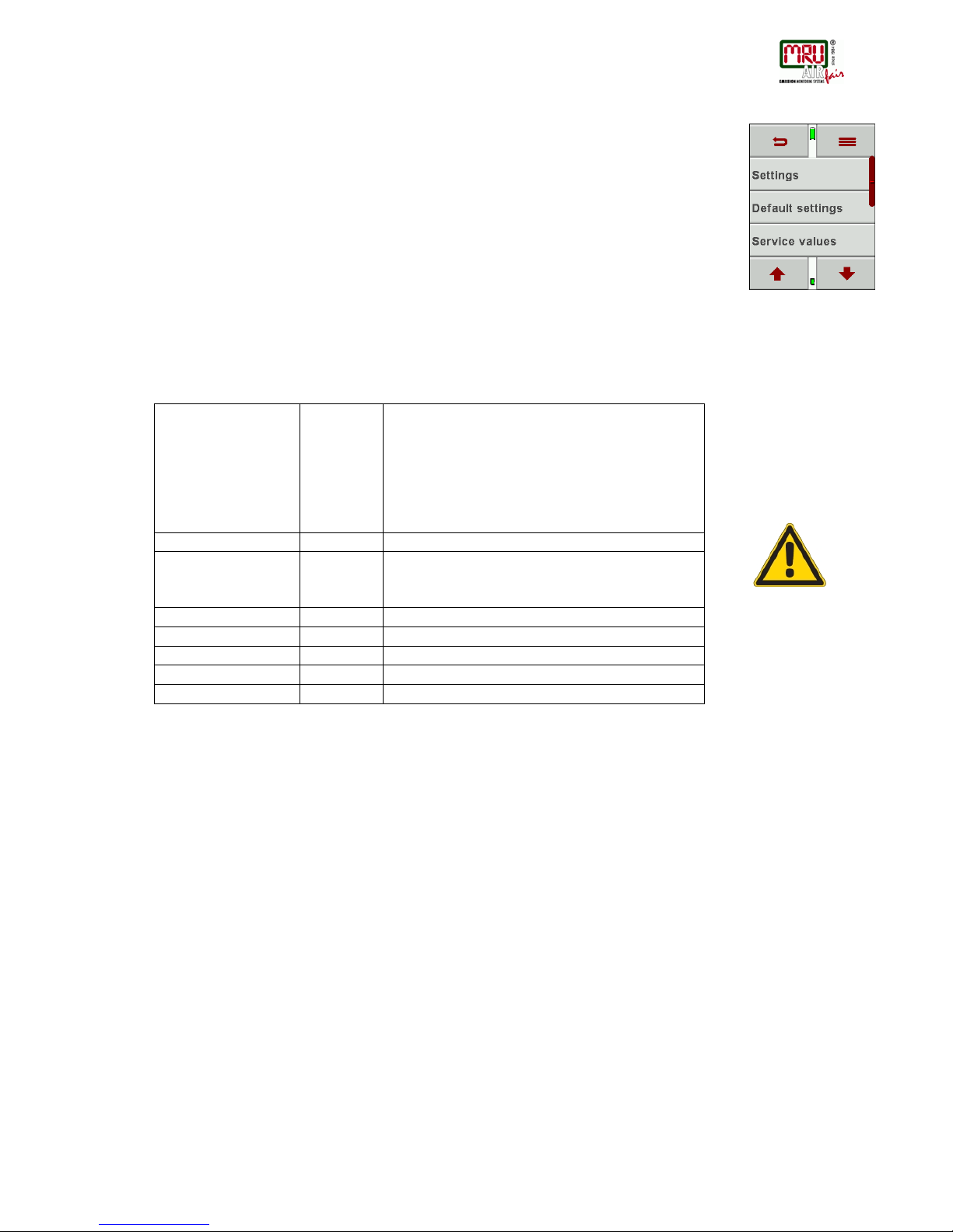
The following adjustments can be made in the „Extras“menu:
Country
When changing the country, country specific pre-
settings and measurement procedures will be
activated.
Please pay special attention if the country specific
settings and procedures are working according to
their regulations.
Language
Select the operating language
LCD brightness [%]
5 – 100
The LCD brightness is depending on temperature
and personal perspective of each user.
50% brightness are normal at 68°F (20°C)
Keyboard beep
ON / OFF
Turn the Keyboard beep ON or OFF
Helping hints
ON / OFF
Turn the feature Helping hints ON or OFF
Measurement
Select the units for pressure and temperature
Logo
ON / OFF
Select if the start logo should be displayed or nor
Printer type
MRU/HP
Select the between MRU protocol and HP protocol
Page 14
USER MANUAL DM9600
MRU GmbH, D-74172 Neckarsulm
14 / 39
Adjusting date and time
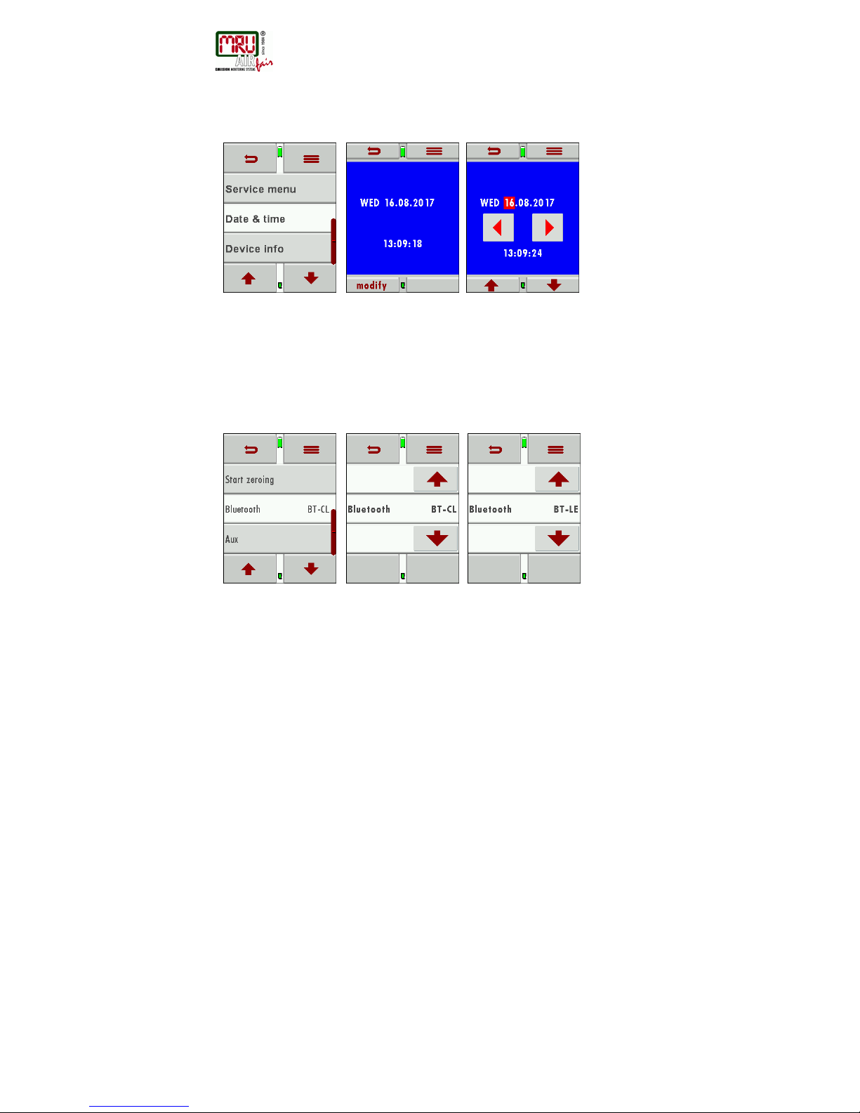
Date and time can be viewed and adjusted in the EXTRAS / Date/Time menu. This device
automatically changes from winter to daylight savings time and back.
The date and time should be adjusted in the internal battery was completely drained.
Modify the date and time with the buttons left/right and up/down
4.3. Bluetooth settings (optional)
The following MRU Software can be used:
MRU4u (Bluetooth) available in the Apple App Store and Google Play Store
The Bluetooth-Passkey (co nn ection code) is: 1234
The Bluetooth mode can be viewed and selected in the EXTRAS / Setting / Bluetooth menu.
Please use BT-CL for connections to Android and BT-LE for connections to IOS.
Page 15

USER MANUAL DM9600
MRU GmbH, D-74172 Neckarsulm
15 / 39
5. Maintenance and care
5.1. Cleaning and care
The DM9600 required only little maintenance:
• Charge the battery completely in case you will not use the analyzer over a
longer period. Then recharge the battery every 6 months (using the included
battery charger connected to the USB port).
Page 16
USER MANUAL DM9600
MRU GmbH, D-74172 Neckarsulm
16 / 39
6. Preparation for each measurement
6.1. Power supply
The DM9600 can be operated optionally:
• With the built in Lithium-Ion battery
• With the included battery charger connected to the USB port
6.2. Automatic Auto-off function
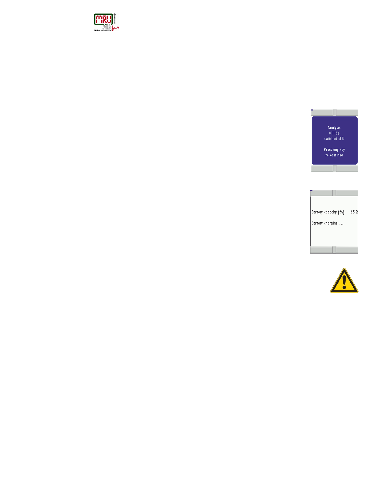
The Auto-off function powers down the device if no key has been touched for 60 minutes.
During measurement and/or battery charging the Auto-off function is deactivated.
The device will give an acoustic signal and will display that it wants to shut down, the
shutdown can be prevented by touching the screen.
6.3. Measuring with grid power supply / Battery charging
The device can be charged by connecting the supplied charger 90...260 V / 50/ 60Hz to
the USB port.
The device can be operated while it is charged.
The device will switch to trickle charge mode once the battery is fully charged.
6.4. Battery charge condition
The battery symbol indicates the battery capacity. The battery symbol will start to flash
every second in red once the battery reaches a remaining operation time of +/- 60
minutes (depending on device configuration). The device will shut down if the batteries
are not charged in time to prevent a total battery discharge.
6.5. Ope r ating temperature
Please pay attention to the allowed operating temperatures for this device.
The device will display should you try and operate it whilst outside of the defined temperature
ranges.
In case the DM9600 was stored at a very cold location you will have to give the device time to
adapt to the warmer environment before powering it up, this will avoid condensation!
The DM9600 is not operable when not within the temperature parameters. After powering up
the device will give acoustic signals during warm up.
6.6. Power up and zeroing
Touch the screen then press the green ON button
During zeroing the device will notice if there are defective sensors and will display an error
message if there are defective sensors.
Repeat zeroing
The zeroing can be repeated at and time.
Page 17
USER MANUAL DM9600
MRU GmbH, D-74172 Neckarsulm
17 / 39
7. Performing a measurement
The DM9600 base version has the complete functionality for you to make pressure and
temperature measurements.
For additional measurements additional accessories must be purchased and used.
7.1. Auto-Log function
The Auto-Log function allows you to define the measuring time and the measuring intervals.
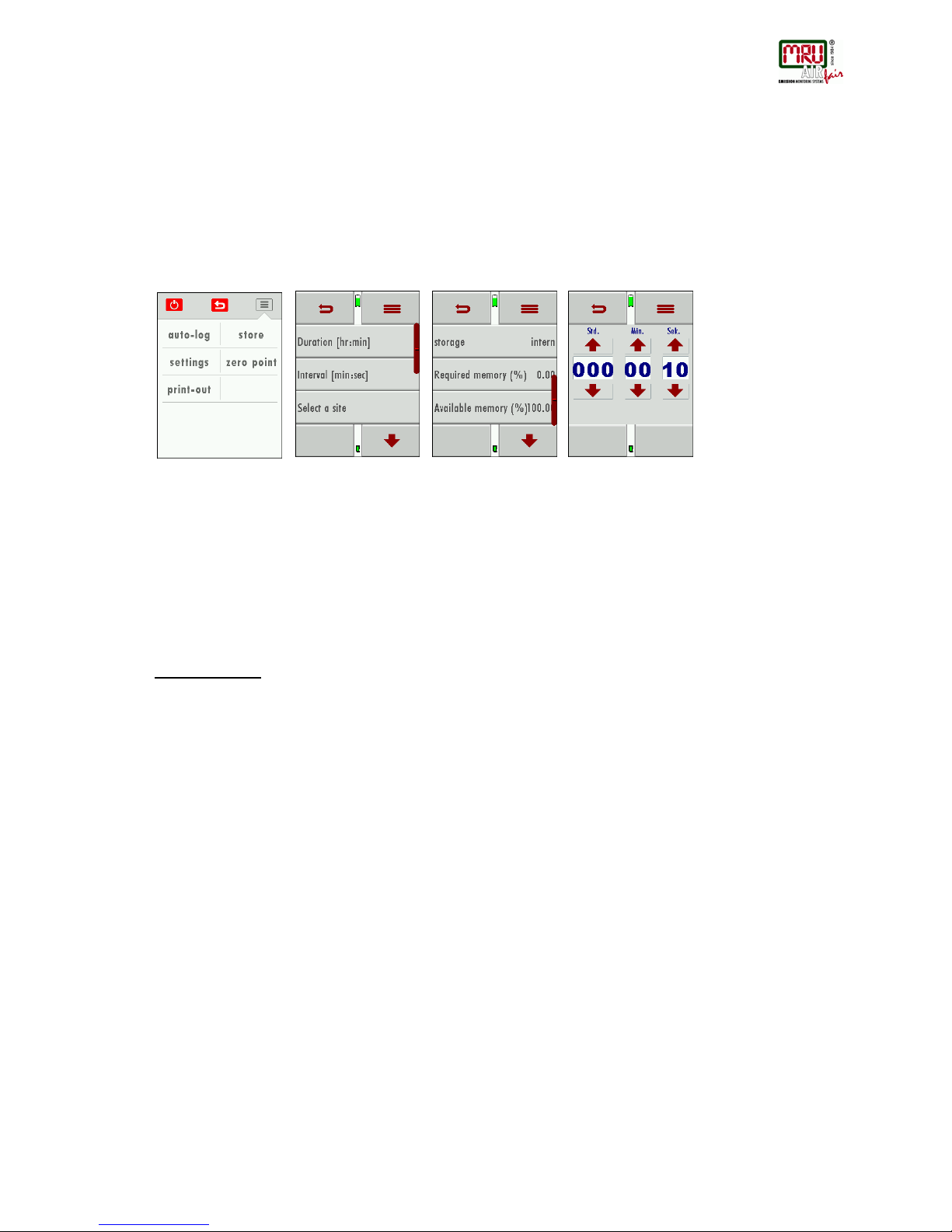
Auto-Log settings:
Measuring time is the complete time for one measurement cycle.
Press the button measuring time to be able to set the measurement time (using the arrows up
and down to change the time).
Press the button interval to select how frequently you want to save the results.
Press the Site Selection to determine to which site the results will be saved to.
Each interval will be saved to the selected site.
The Auto-Log can save results either on the internal memory or onto the SD Card.
Press the Store button and then select where the results should be stored.
Please make sure that there is enough storage space available.
Press the start button to start the Auto-Log, it will end automatically after the defined
measurement time has elapsed.
Page 18
USER MANUAL DM9600
MRU GmbH, D-74172 Neckarsulm
18 / 39
7.2. General measurement
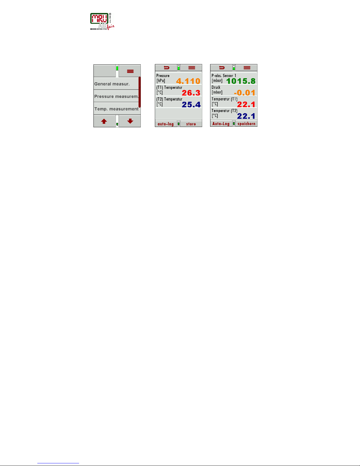
During the general measurement, the measured pressure as well as measured temperature
are displayed, the values can be Auto-logged and saved.
The absolute pressure can also be displayed (optional)
Context menu:
Auto-Log: Measurements are being logged
Store : S ingle measur emen ts are saved
Adjustm. : The units can be selected
Zeroing : The pressure value is set to zero
Print : The measurement results are being printed (IR printer is needed)
Page 19
USER MANUAL DM9600
MRU GmbH, D-74172 Neckarsulm
19 / 39
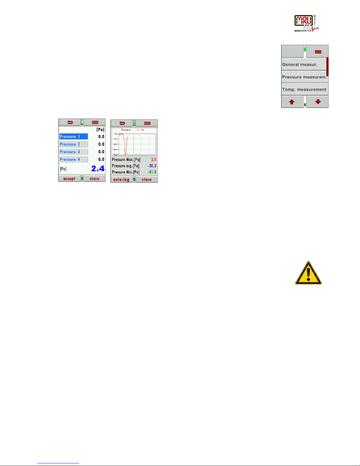
7.3. Pressure measurement
Press Pressure measurement to enter this menu.
On the first page of the pressure measurement 4 pressure values can be recorded.
The current displayed pressure value can be assigned and saved to one of the 4 available
spots.
The adjustments are done in the context menu.
The hose (e.g. draft measurement) will be connected to the draft port P1.
For differential pressure measurements, a second hose will be connected to the P2 port.
On the second page, the pressure flow is visualized in a graph. The pressure can be Autologged (see Auto-Log function). When saving results, the max and min values are saved as
well as the pressure average.
Context menu
Zeroing: The pressure value is set to zero
Auto-Log: Measurements are being logged
Store: Single measurements are saved
Adjustm. : Units and damping time of the pressure measurement can be adjusted
Page +: turn to next page
NOTE:
The pressure sensor will be destroyed if the supplied pressure is too high!
The following warning will be displayed:
Error message “Pressure too high“
There will also be an additional acoustic warn signal.
Page 20
USER MANUAL DM9600
MRU GmbH, D-74172 Neckarsulm
20 / 39
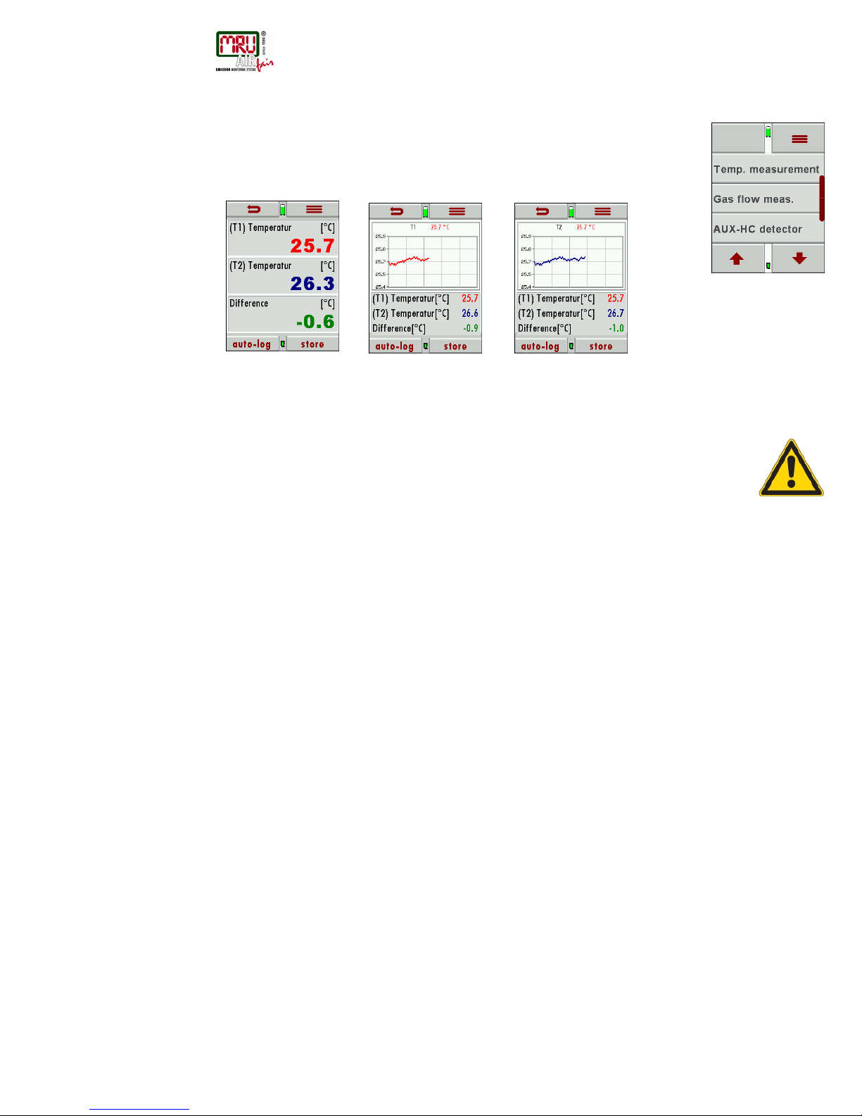
7.4. Temperature measurement
In the menu temperature measurement, 2 temperatures can be measured. The K-Type
temperature sensors are connected at port T1 and T2 – the temperatures T1 and T2 will
be displayed as well the temperature difference. The temperatures can be saved or Autologged. On pages 2 and 3 temperatures are displayed as graph.
Context menu
Auto-Log: Measurements are logged
Store: Measurements are saved
Print: Measurements are printed (external IR printer)
Page - : turn to previous page
Page +: turn to next page
NOTE:
The measurement accuracy can only be granted with original MRU temperature
sensors!
Page 21
USER MANUAL DM9600
MRU GmbH, D-74172 Neckarsulm
21 / 39
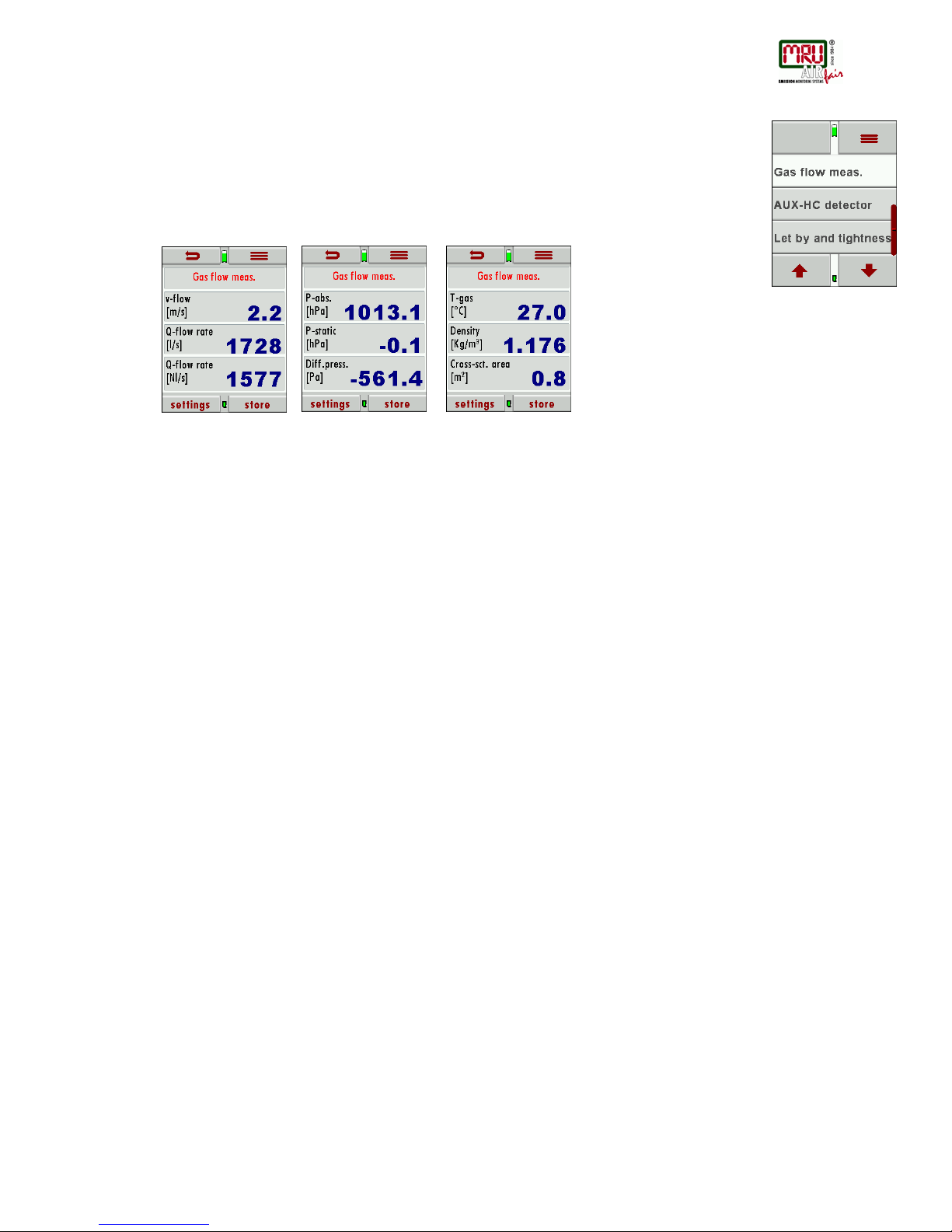
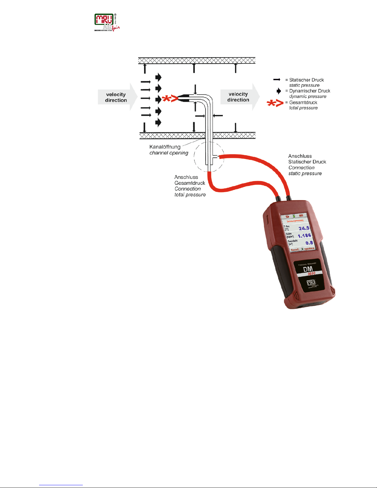
7.5. Flow velocity measurement (option)
In this menu, the flow velocity can be determined.
On page 1 the flow velocity as well as the n orm volume are displayed. On page 2 the absolute
pressure, the static pressure and differential pressure is displayed.
On page 3 the gas temperature, the gas density and the duct cross section is displayed.
Measurements can be saved or Auto-logged.
Context menu:
Settings: Set measurement units, gas density and pitot factor
Store: Measurements can be staved
Zero point: Pressure value will be set to zero
Auto-Log: Measurements are logged
Print out: Measurements are printed (external IR printer)
Page - : turn to previous page
Page +: turn to next page
Page 22
USER MANUAL DM9600
MRU GmbH, D-74172 Neckarsulm
22 / 39
Connecting the Pitot tube:
Page 23
USER MANUAL DM9600
MRU GmbH, D-74172 Neckarsulm
23 / 39
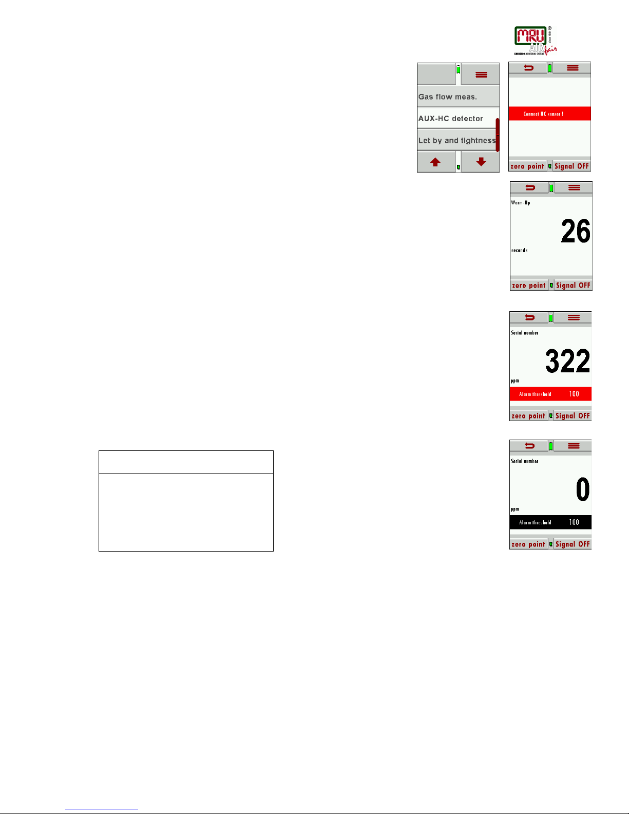
7.6. Leak detection using the external HC-Probe (option)
The external HC probe can be connected to the AUX port (if equipped) and is
used for leak detection.
Please make sure that the red dot on the AUX port and the red dot on the HC
probe plug are aligned when connecting the HC probe to the DM9600.
There will be a red flashing information (connect HC probe) on the screen in case the HC
probe has not been connected yet.
After the HC probe has been connected the red flashing information will be replaced with the
serial number of the HC probe.
During the warm up phase (zeroing) you will see a count down from 30 to 0 on the display.
Performing a leak test
The HC probe will be ready after zeroing.
There are user definable alarm settings, values below the alarm value will be displayed in
black and value above the alarm setting will be displayed in red. Additional to the red value
there will be an acoustic signal to indicate that the value is above the threshold.
User definable alarm settings (threshold) and zeroing
Modifying the alarm threshold and zeroing
Peak value
The measured peak value will be displayed above the threshold bar.
This value can be reset with zero point.
The max value will also be set to zero during zeroing.
Maintenance
It is recommended to calibrate the HC sensor annually to ensure accurate readings. The
functionality of the HC probe can be tested with the gas of a cigarette lighter (without flame) or
a test gas from a gas cylinder.
Zeroing
Threshold activate/deactivate
Gray bar: Threshold deactivated/Alarm
OFF
Red bar: Threshold activated/Alarm ON
Page 24
USER MANUAL DM9600
MRU GmbH, D-74172 Neckarsulm
24 / 39
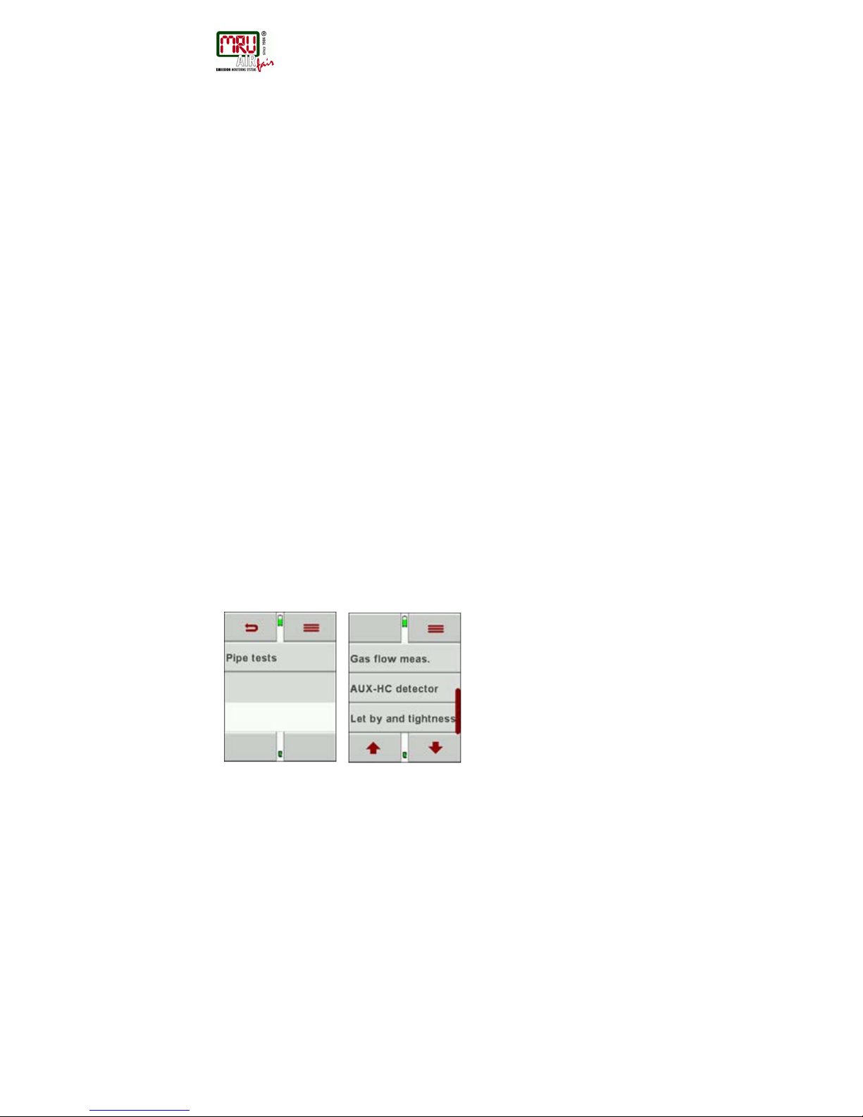
7.7. Usage capability test (option)
What is the usage capability test?
The Usage capability test helps to determine and judge leakages (gas leakage) in low
pressure gas pipes.
Tested will be all in operation or repaired pipes with all faucets, however without gas units and
their regulators and security devices. The gas meter can be included in this test (using
backward test).
The usage capabilities test my not be performed when:
New installed pipes (= pipes within warranty)
Pipes that had a limited usage capability or a NO usage capability and had been repaired to
be used
Not in use pipes which want to be used again
Pipes in middle- and high-pressure range.
Test medium: Air or Methane
Test pressure: 23 mbar according to DVGW worksheet G600.
Unlimited usage capability: > 0 l/h to < 1,0 l/h
The pipe can be used for unlimited time without repair.
Limited usage capability: >1,0 l/h up to < 5,0 l/h
The pipe may be used for a maximum of 4 weeks. Within these 4 weeks the pipe must be
repaired to achieve Unlimited Usage Capacity again (Leak-tight test).
NO usage capability: > 5,0 l/h
The use of this pipe must be stopped immediately. Take action to determine the defect.
Important is the technical security judgment:
Also, a leak tight gas pipe can have limited or no usage capability. The physical condition
must be considered as well!
Once you smell gas the system is leaking. The above-mentioned usage capability grading’s
do not apply.
Page 25
USER MANUAL DM9600
MRU GmbH, D-74172 Neckarsulm
25 / 39
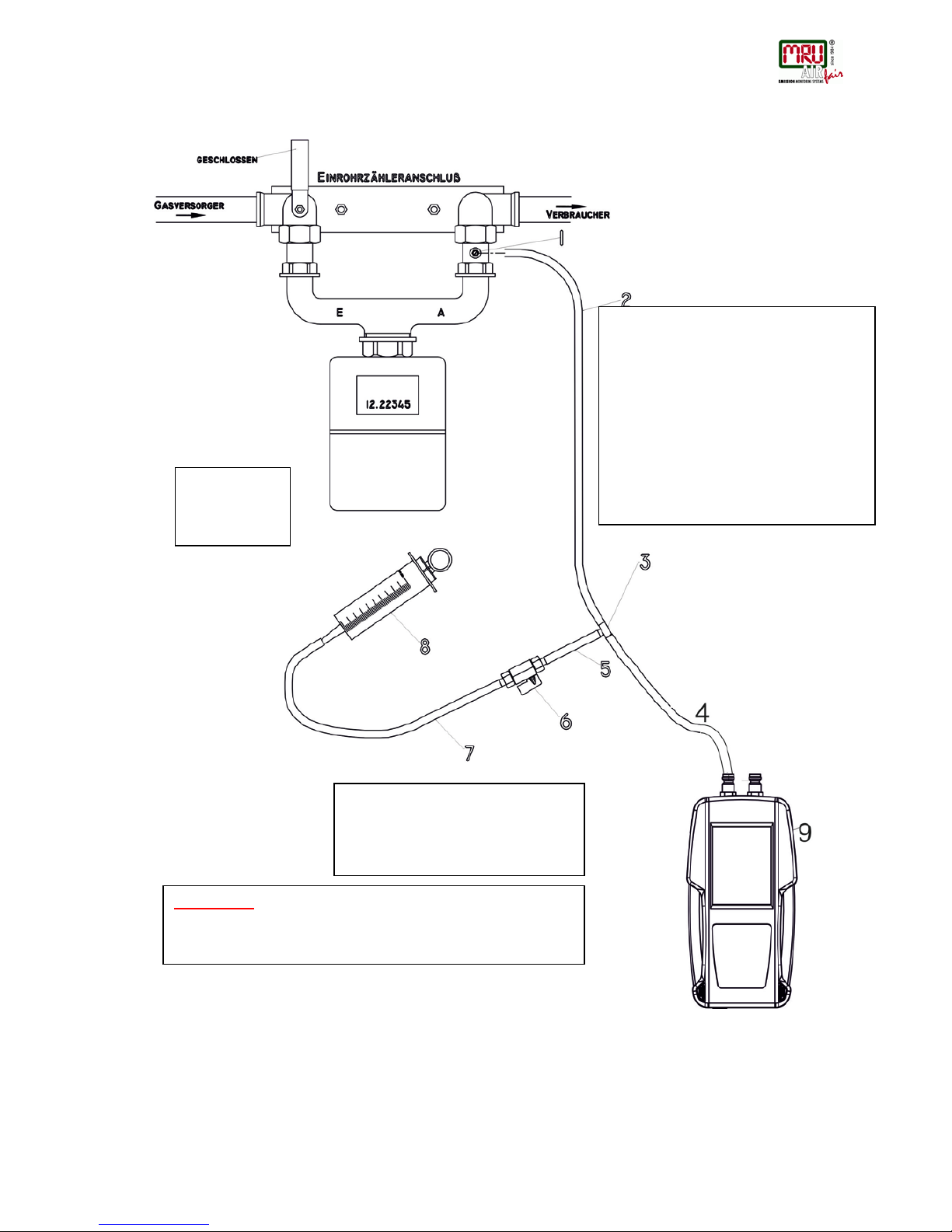
Connection diagram usage capability test without dismounting gas meter
1 # 59387 Test port
2 # 50482 Silicone hose 6x2
3 # 59074 T-connector 3x6 mm
4 # 50482 Silicone hose 6x2
5 # 50482 Silicone hose 6x2
6 # 59047 Mini ball valve
7 # 50482 Silicone hose 6x2
8 # 61499 Syringe 108 ml
9 DM9600
108 ml =
Syringe not
pulled
ATTENTION:
Slowly pull out the syringe piston to have pressures lower
than < 50 mbar on the DM9600.
Pressures higher than 100 mbar can
occur when pulling out the syringe
piston rapidly.
Page 26
USER MANUAL DM9600
MRU GmbH, D-74172 Neckarsulm
26 / 39
Operation
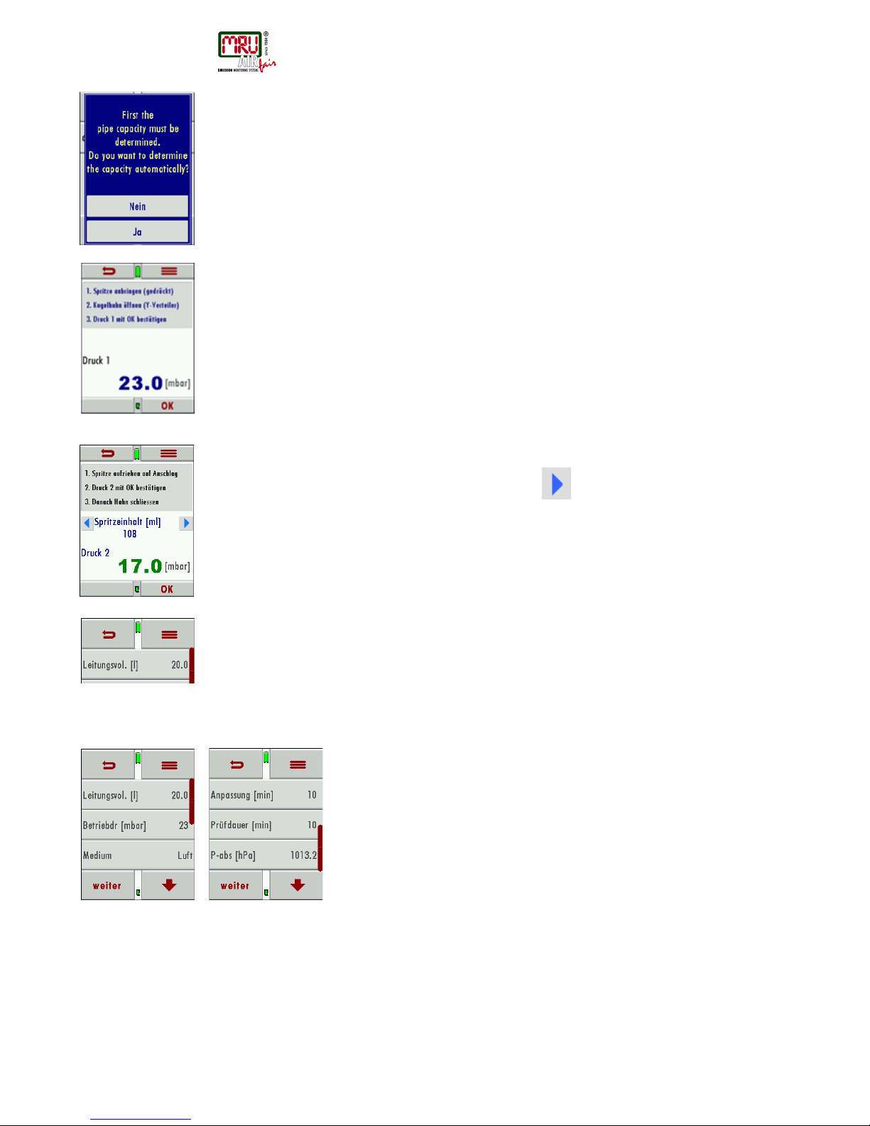
To be able to calculate the leakage rate first the pipe capacity must be determined.
In the first screen of the usage capability test you are asked if you want to determine the pipe
capacity automatically. As alternative you can insert the pipe capacity manually.
No - Enter pipe capacity manually
Automatic capacity determination
The capacity determination is done by extracting a defined volume from the closed pipe
system using the syringe. The DM9600 uses the pressure drop to calculate the pipe volume.
Please follow the instructions on the DM9600 screen.
The syringe volume is not big enough to achieve the wanted differential pressure, if the pipe
volume is bigger than (>200 Liter). This will be indicated with a red pressure value.
In this case the syringe volume can be increased using the
button and you can take an
additional syringe volume.
Continue with entering all additional parameters
Entering pipe volume manually
Enter the calculated pipe volume.
Entering range is 3 to 1000 l (standard value is 20 l).
The DM9600 will calculate with 3 l should the calculated value be smaller than 3 l.
Entering additional parameters
Entered operating pressure lower than 30 mbar – a reference operating pressure of 23 mbar
will be used for calculations.
Entered operating pressure higher than 30 mbar – the actual entered value will be used for
calculations.
Under “MEDIUM” you can select between air and Methane. It is important to select the
medium that you are using to get the correct results. Methane can escape easier than air in a
leakage situation.
The results are always based on Methane
Min value
Max value
Standard value
Operating
pressure
15
100
23
Adaptation time
1
80
5
Test duration
1
20
1
P-abs
800
1200
1013
Page 27
USER MANUAL DM9600
MRU GmbH, D-74172 Neckarsulm
27 / 39
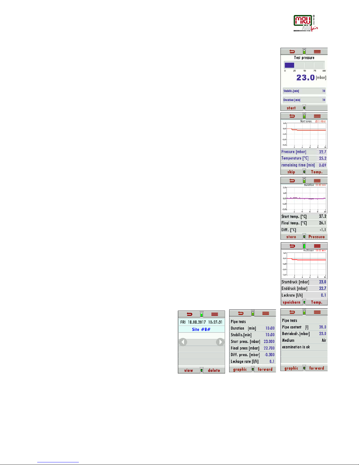
Apply test pressure
This window is used to pressurize the pipe section that needs to be tested. There will be a red
bar should the pressure be below 20 mbar and there will be an error message when starting
the test.
Adaption phase
The adaption phase can be shortened by using the “Skip” button. With the „Temp „button the
temperature curve will be displayed.
The test starts automatically at the end of the adaption phase
Test phase
The usage capability test is now active. With the „Temp “button the temperature curve will be
displayed
The temperature curve can be used to evaluate the test results. A drop of temperature during
the test phase can be the reason for a slight pressure drop. There is not automatic
temperature compensation for the pressure!
Display results
The start pressure, end pressure and the resulting leakage rate will be displayed at the end of
the test.
Results can be saved using the „store „button
Storing test results
Results should be assigned to a site. Here you will assign your results to a site.
Results can be saved using the „store“button
With Back, you will reach the measurement menu
This is the bottom part of a test result
Results can be viewed once they have been stored.
Additional parameters can be viewed using the
arrows up and down.
7.8. Pri nti ng m easurement results
Measured results can be printed in all measurement programs using the print button in the
context menu. All values will only be printed once even those which are displayed more than
once.
Page 28
USER MANUAL DM9600
MRU GmbH, D-74172 Neckarsulm
28 / 39
8. Data storage
8.1. Data storage structure
The main component of data storage is the site. Each site has a distinct site number and 8
user definable text components which can be used for the address, customer name and so
on. The DM9600 can save up to 500 different sites.
New sites can be generated. Modifications and additions can be transferred using the PC
program MRU Win.
Attention: Sites that have been created in the DM9600 will NOT be transferred back to the
PC. Only measurement results will be transferred from the DM9600 to the PC which will be
identified by the site number.
Measurement results are stored and must be assigned to a site.
8.2. Measurements in the data storage menu
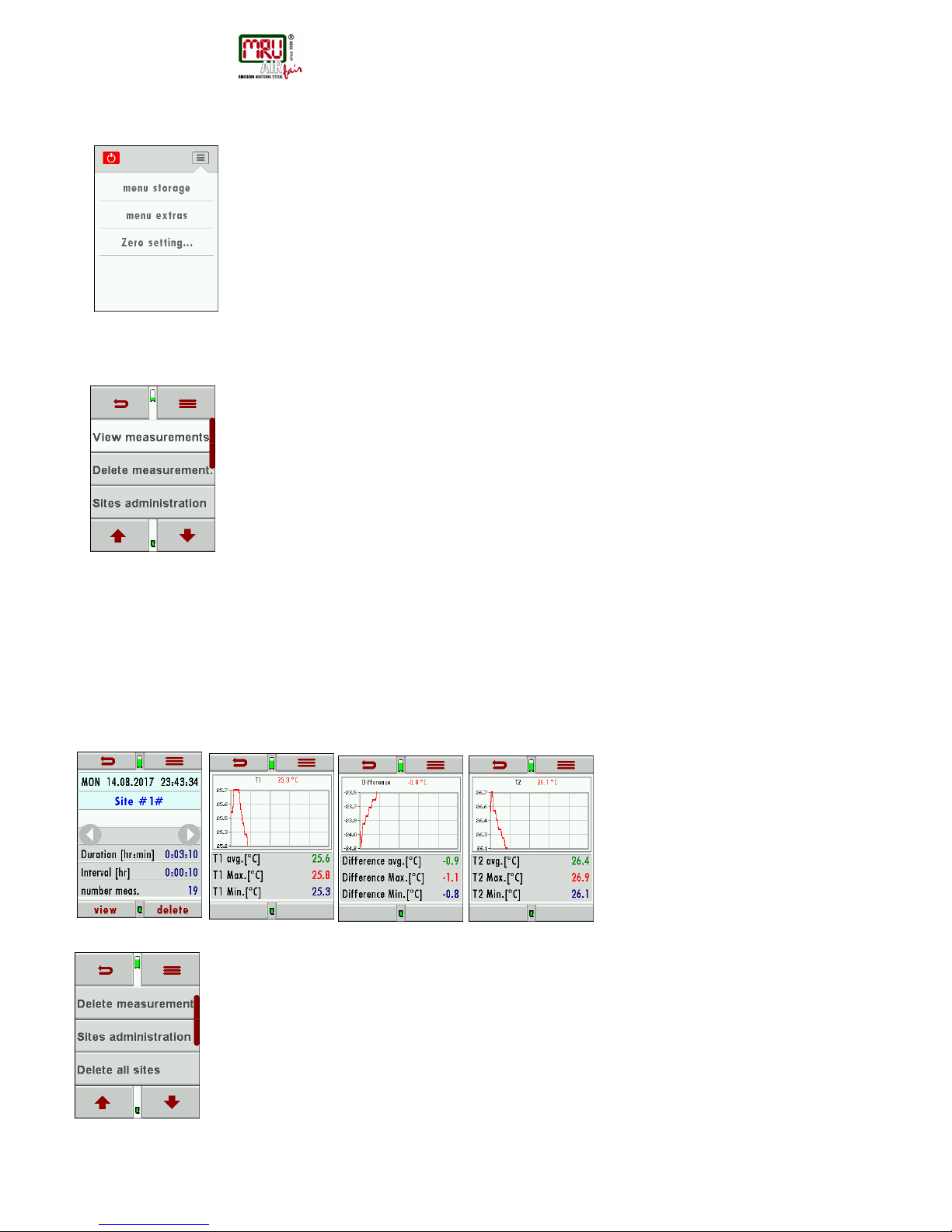
View measurements
Measured results can be viewed in the menu „view measurements“.
Once selected you will see an overview of the different measurement modes with the number
of saved results for each mode.
• Select one of the available modes.
• You will first see context information about the stored measurement. Use
the arrow buttons to jump in between different stored measurements.
• Press „view“to s ee the details of the selected measurement. Results will be
displayed as they are defined in the measurement screen.
With „back „you will return to the context information screen.
Only logged measurements will display the measured time, the interval and the number of
measurements.
Attention:
It may take a bit longer to read the results if the number of measurements or the logged
measurements have a high data volume.
Delete measurements
You can:
• Delete single measurements when pressing the delete button while the
measurement is being displayed.
• Or delete all measurements of a measurement mode. You will be asked to
confirm your intention to delete all measurements.
Page 29
USER MANUAL DM9600
MRU GmbH, D-74172 Neckarsulm
29 / 39
8.3. Sites
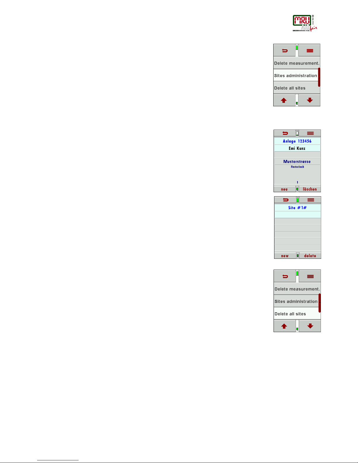
In the menu sites, you can:
• View all data of the stored site
• Add new sites
• Delete sites
• Any modifications to the sites will not be transferred to the PC
Attention:
Sites created in the DM9600 will not be transferred to the PC.
View sites
In the menu „Sites administration“each site will be displayed with:
• The distinct site number, which is displayed in blue to indicate it’s
significance,
• And addition 8 user definable fields.
You can page through the sites using the arrow buttons left and right.
Add new sites
New sites can be added and modified in the „Sites administration“menu.
Select “new” to add a new site. You will then see:
• The first line which must have a distinct site number for identification. The
DM9600 can also create a new site number (the next available site number
will be selected).
• All other lines are user definable lines for address, customer name and so
on.
(These lines can only be filled with a PC program like the MRU4Win)
Delete sites
You can
• You can delete single sites in the menu „Sites administration“ by selecting
delete in the context menu,
• Or you can delete all sites at once
You will be asked to confirm your intention to delete all sites.
Page 30
USER MANUAL DM9600
MRU GmbH, D-74172 Neckarsulm
30 / 39
8.4. Data transfer using the SD-Card
For data transfer, we use the CSV format
CSV is a simple file format used to store tabular data, such as a spreadsheet or database.
Files in the CSV format can be imported to and exported from programs that store data in
tables, such as Microsoft Excel or OpenOffice Calc. CSV stands for "comma-separated
values"
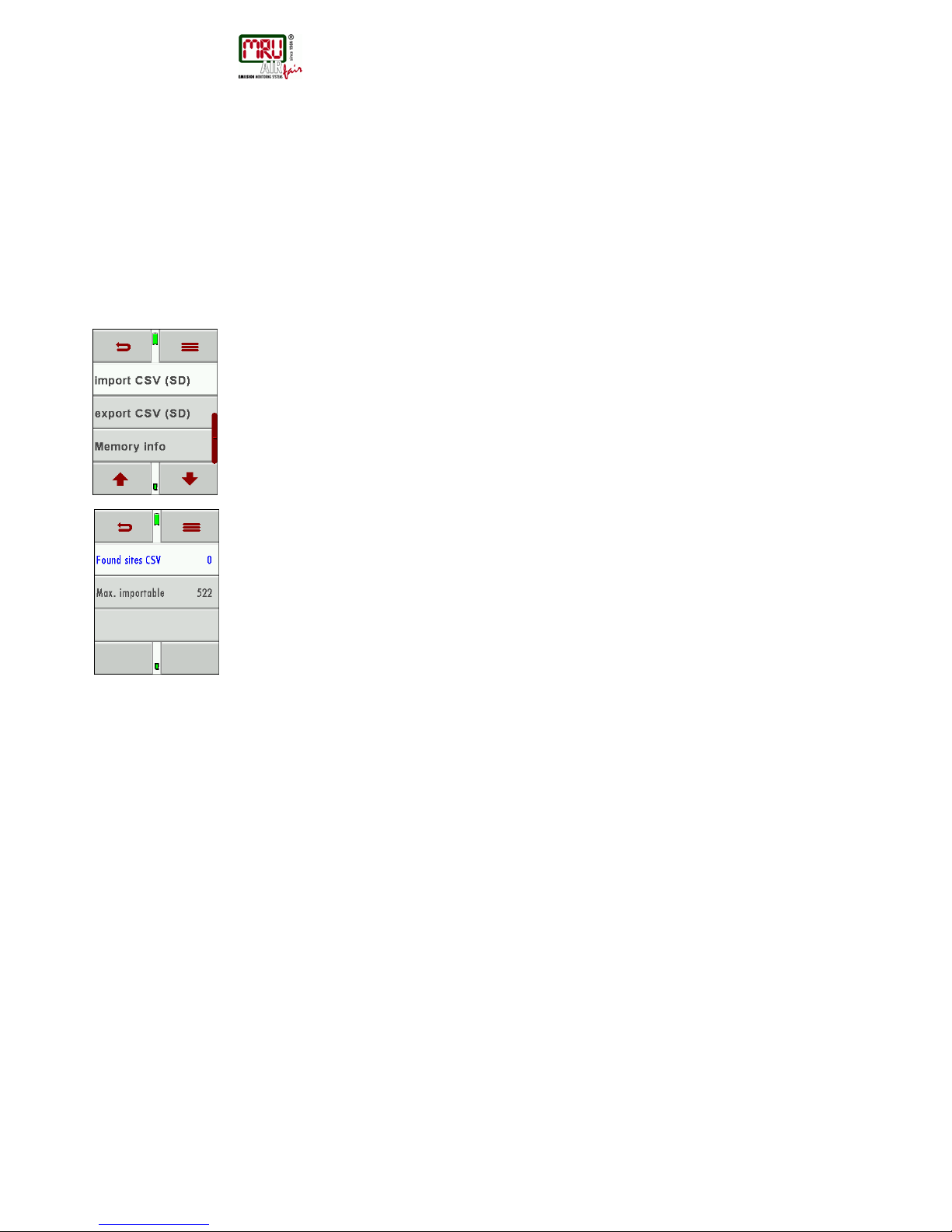
• Import of sites Anlagen
• Export of sites
• Export of saves measurements
Import of sites
This function can be used to transfer a CSV file that has been created on a PC.
IMPORTANT: The file name must be “analgen.csv”!
The file may not contain any header information, meaning, the first line will contain actual
data.
Each line that is not empty and which doesn’t start with a comma (both would result in an
empty site number which is not permitted) will be transferred.
Each line and/or data set a maximum of nine lines will be transferred. A maximum of 24
numbers and letters are allowed for each line, everything longer than 24 letters/numbers will
be cut off.
A1-F1,A1-F2,A1-F3,A1-F4,A1-F5,A1-F6,A1-F7,A1-F8,A1-F9
A2-F1,A2-F2,A2-F3,A2-F4
A3-F1,A3-F2,,A3-F4,
A4-F1,,,A4-F4
A5-F1
Examples with 3 invalid sites: (reason for error)
,A1-F2,A1-F3,A1-F4,A1-F5,A1-F6,A1-F7,A1-F8,A1-F9 (Comma at the beginning)
(Space)
,A3-F2,A3-F3,A3-F4,A3-F5,A3-F6,A3-F7 (Comma at the beginning)
Important:
No check is performed inside the file or the DM9600 for duplicate site numbers (line1).
The DM9600 can handle duplicate numbers, however that can be difficulties later to assign
measurements to site numbers when exporting these back to the PC.
(see also 3. + 4. Export of measurements)
The DM9600 will mark duplicate site numbers after import. If the same file is imported to the
same DM9600 an indication will be displayed in red letters.
Page 31
USER MANUAL DM9600
MRU GmbH, D-74172 Neckarsulm
31 / 39
Exporting sites
This function can either be used as backup of the sites to a PC or to transfer them to a
different DM9600. This is very useful especially when modifications (like modified telephone
number, etc.) have been made manually in the Sites Administration of the DM9600 and these
modifications need to be updated in the PC program. Or, if the same sites must be installed in
a second DM9600.
The format of this file is identical as the one described in “Import of sites”.
Only the file name is different, in this case “ANLxxxxx.csv”. The xxxxx in the file name are
consecutive numbers containing zeros. The exported file can be used to import the sites into
another DM9600, however the name must be changed to “anlagen.CSV” before it can be
used for import.
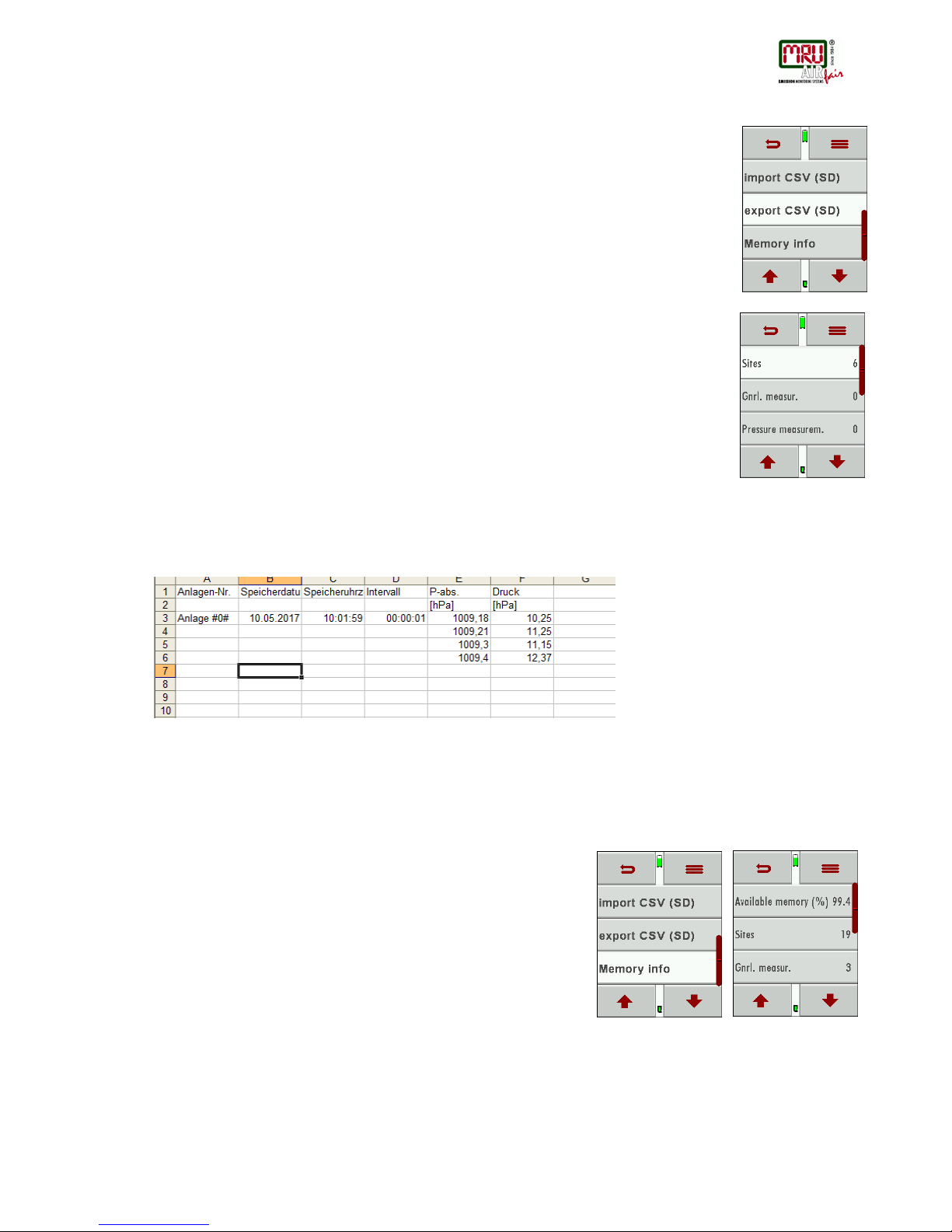
Exporting measurements
This function is used to export measurements to a PC.
Attention: this is not a backup function and the results can’t be transferred to another
DM9600!
The created file has the file name “TMPxxxxx.csv” the xxxxx in the file name are consecutive
numbers containing zeros
The created file has a header with information like, Site number, Date/time, measuring values
and units, all the information that is also stored inside the unit.
Here is an example:
Attention:
It can take up to 2 minutes to export measurements, depending on the number of
measurements that are being exported.
8.5. Information about the data storage
In the „menu storage „you select „Memory info” to get information about
the available storage capacity of the unit. You will see the number of
stored sites (max 500) and the number of stored measurements (max
1000).
Page 32
USER MANUAL DM9600
MRU GmbH, D-74172 Neckarsulm
32 / 39
9. EXTRAS / Settings
The DM9600 leaves our factory with standard firmware settings, and in most cases, this will
cover your daily needs. However, these settings are adjustable and customizable to make
work even easier.
9.1. Service adjustment menu
The service adjustment menu is PIN code protected. Only authorized and trained personnel
may enter this menu.
You will be prompted back to the “settings menu” once you have entered a wrong PIN code.
Please contact a MRU service partner (www.mru.eu
) to get the correct PIN code.
9.2. Factory settings
The DM9600 will be reset to factory settings:
Settings
LCD brightness (%) 50
Helping hints ON
Keyboard beep ON
9.3. Service values
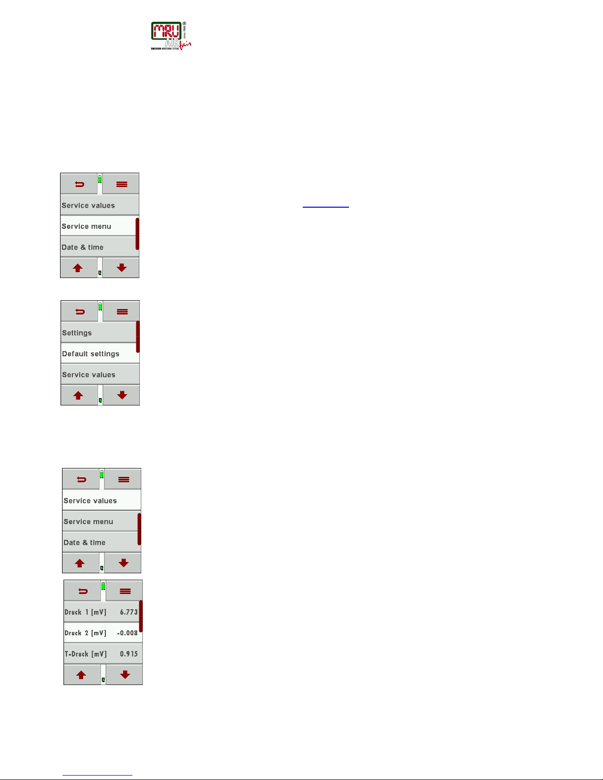
Device errors can often be determined by using the values in the “service vales” menu.
The service values of all installed sensors are displayed here.
Please contact your local MRU service partner in case you have a malfunction of your device.
It’s always handy to have the device next to you when make a service call, most likely the
technician will ask you for these values and the serial number of the device.
Page 33
USER MANUAL DM9600
MRU GmbH, D-74172 Neckarsulm
33 / 39
10. Appendix
10.1. Technical details
General data
Prüfmedien
non-aggressive gas
suitable for
Durchmesser Anschluß Druck-
/Unterdruck
8,0 mm
Connector diameter
Größe Silikonschlauch
Ø 6 x 2 mm
Size silicone hose
Betriebstemperatur
5 to 40 °C
41 to 104°F
Operating temperature
Lagertemperatur
- 20 - + 50 °C
-4° to 122°F
Storage temperature
Anzahl und Typ Batterien
Li-Ion
Qty and size of batteries
Betriebsdauer
20h
Operating time
Display
2,8″ touch TFT
Display
Gehäusematerial
PA6GF30
Housing material
Schutzart
IP30
IP degree of protection
Gewicht
340 g
12 ounces / 0.7 lbs.
Mass
Maße
83x38x180 mm
3.27“ x 1.50“ x 7.08“
Size
Page 34
USER MANUAL DM9600
MRU GmbH, D-74172 Neckarsulm
34 / 39
Messgenauigkeit / Accuracy
Sensor
±75 hPa (mbar)
Sensor
Messbereich
-75,0 hPa ... +75,0 hPa
Range
Auflösung
0,1 Pa
Resolution
Genauigkeit abs / vom
Messwert
± 2,0 Pa / 0,5%
Accuracy abs. / reading
Temperatureinfluß (typisch)
(0 ... 50 °C): ±0,4 %
(32 ... 122°F): ±0.4 %
Temp
. variation (typical)
Sensor
±150 hPa (mbar)
Sensor
Messbereich
-150,0 hPa ... +150,0 hPa
Range
Auflösung
0,01 hPa
Resolution
Genauigkeit abs. /vom
Messwert
± 0,03 hPa / 0,5 %
Accuracy abs./reading
Temperatureinfluß (typisch)
(0 ... 50 °C): ±0,4 %
(32 ... 122°F): ±0.4 %
Temp. variation (typical)
Sensor
±350 hPa (mbar)
Sensor
Messbereich
-350,0 hPa ... +350,0 hPa
Range
Auflösung
0,01 hPa
Resolution
Genauigkeit abs. /vom
Messwert
± 0,3 hPa / 0,5 % Accura
cy abs./reading
Temperatureinfluß (typisch)
(0 ... 50 °C): ±0,5 %
(32 ... 122°F): ±0.5 %
Temp. variation (typical)
Sensor
±1.000 hPa (mbar)
Sensor
Messbereich
-1000,0 hPa ... +1.000,0 hPa
Range
Auflösung
0,1 hPa
Resolution
Page 35
USER MANUAL DM9600
MRU GmbH, D-74172 Neckarsulm
35 / 39
Genauigkeit abs. /vom
Messwert
± 1,0 hPa / 1%
Accuracy abs./reading
Temperatureinfluß (typisch)
(0 ... 50 °C): ±0,5 %
(32 ... 122°F): ±0.5 %
Temp. variation (typical)
Sensor
±7.000 hPa (mbar)
Sensor
Messbereich
-7,000 bar ... +7,000 bar
Range
Auflösung
1 hPa
Resolution
Genauigkeit abs. /vom
Messwert
± 1,0 hPa / 1%
Accuracy abs./reading
Temperatureinfluß (typisch)
(0 ... 50 °C): ±0,5 %
(32 ... 122°F): ±0.5 %
Temp. variation (typical)
Temperaturmessung
T1, T2
Temperature Measurement
Anzahl der Thermoelement Typ
K - Eingänge
2
Number of thermocouple type
K input
Messbereich
-40 °C .. 1200 °C
-40 °F .. 2192 °F
Measuring Range
Genauigkeit
±1°C / 0,5%
±2°F / 0,5%
Accuracy
Page 36
USER MANUAL DM9600
MRU GmbH, D-74172 Neckarsulm
36 / 39
10.2. Firmware update
How to install a new firmware into the DM9600
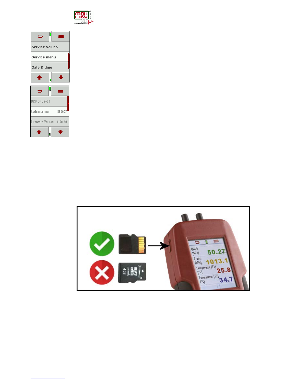
Turn on the device. Select the context menu / extras / device info
In the 3rd line you will see the current installed firmware version for example 1.00.05
We will need the following information from you in case something has gone wrong with the
update.
Please write down the firmware version of your device _______________________________
Please write down the serial number of your device _________________________________
Performing and verification of an update
Preparing a SD card
Typically, you will receive an update by email. You will have to unzip the file in case you have
received the file in a zip format (you would do this on your PC).
Now you will copy the unzipped file „1128.fwb“ onto the root directory of the SD card.
Performing the update:
• Copy the 1128.fwb file onto the root directory of the SC card
• Insert the SD card into the card reader of the device and startup the device
ATTENTION:
The SD card contact pins must face towards you when you insert them into the
device and must snap into place once inserted.
Slightly push the SD card into the device and let go again to release the SD
card!
• Please wait, until you see the message „New firmware…found“
• Select and confirm „install firmware“
• The update procedure will start...
• This will take about 45 seconds, don’t press any keys during the update
• The device can be started again once the update has been installed
• You will get the information „Firmware update was performed…“ confirm with OK
• Done
Page 37

USER MANUAL DM9600
MRU GmbH, D-74172 Neckarsulm
37 / 39
How can I verify that the update was successfully?
Turn on the device. Select the context menu / extras / device info
In the 3rd line you will see the current installed firmware version for example 1.00.05
What can I do if see that the old firmware version number is still displayed?
Repeat the update procedure.
Who can help me if I can’t perform an update?
Contact your local sales office or send an email to: [email protected]
10.3. Trouble shooting
Device trouble shooting
1. Effect
2. Error
3. Reason
4. Solution
Device shows no
reaction
Device doesn’t react to any
touch screen commands.
Press the reset button
Device is too cold
and can’t be used.
Display notice:
“Device too cold” or
A beep every 5 seconds
e.g. Device was stored in
the trunk of a car during
winter time.
Take the device into a warm
room and give it time to adapt to
the room temperature!
Device can’t be
turned on or doesn’t
react once powered
up.
Battery drained.
Connect the device to the battery
charger and charge the battery.
Wrong temperature
measurement results
Gas temperature too
high or jumping
K-Type plug not connected
properly
Broken wire or broken
thermo-couple.
Check the connection
Check the wire for damages
Remove condensate drops from
thermo-couple tip.
Page 38
USER MANUAL DM9600
MRU GmbH, D-74172 Neckarsulm
38 / 39
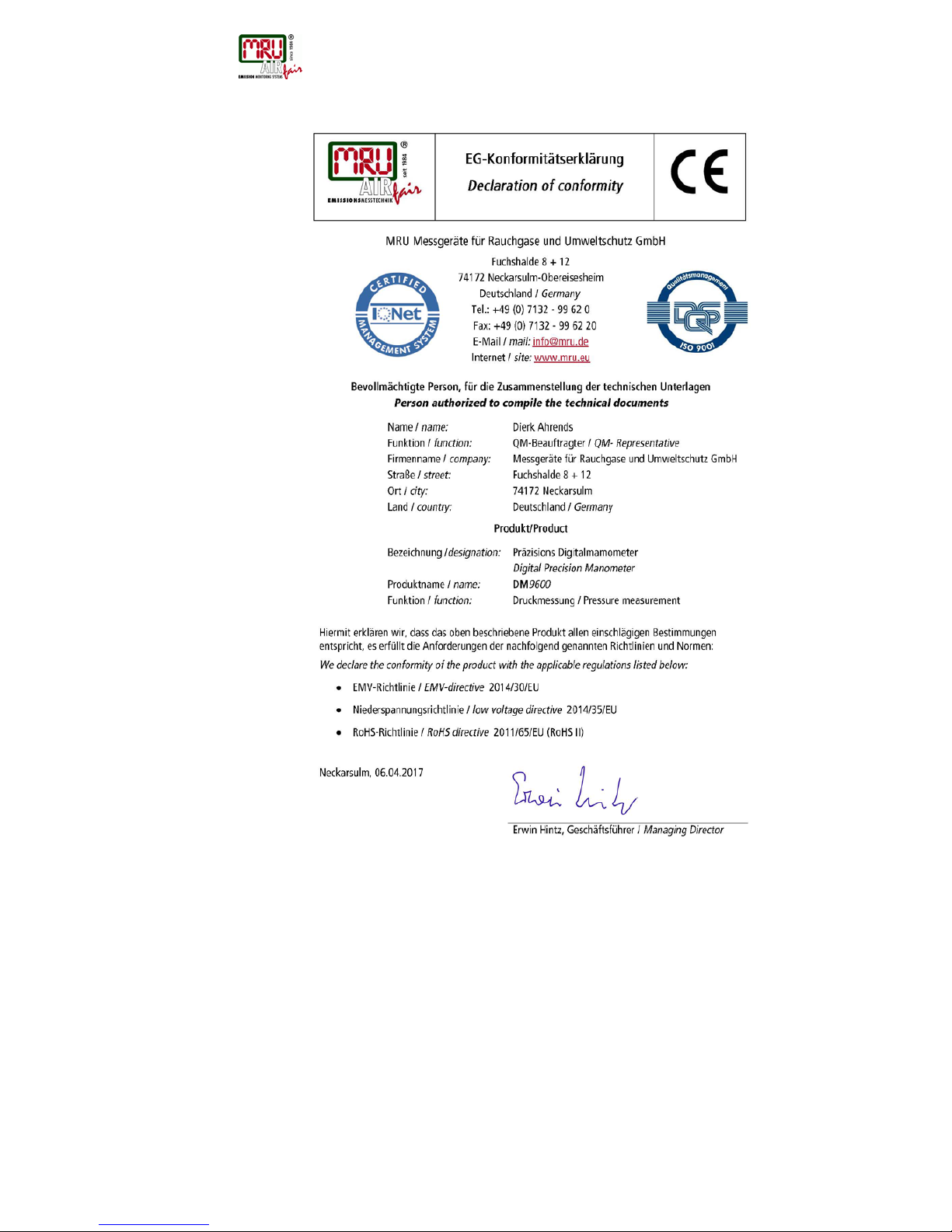
10.4. Declaration of conformity DM9600
Page 39
USER MANUAL DM9600
MRU GmbH, D-74172 Neckarsulm
39 / 39
Technical data change w/o notice Date of issue: 20170821
 Loading...