

Page 1
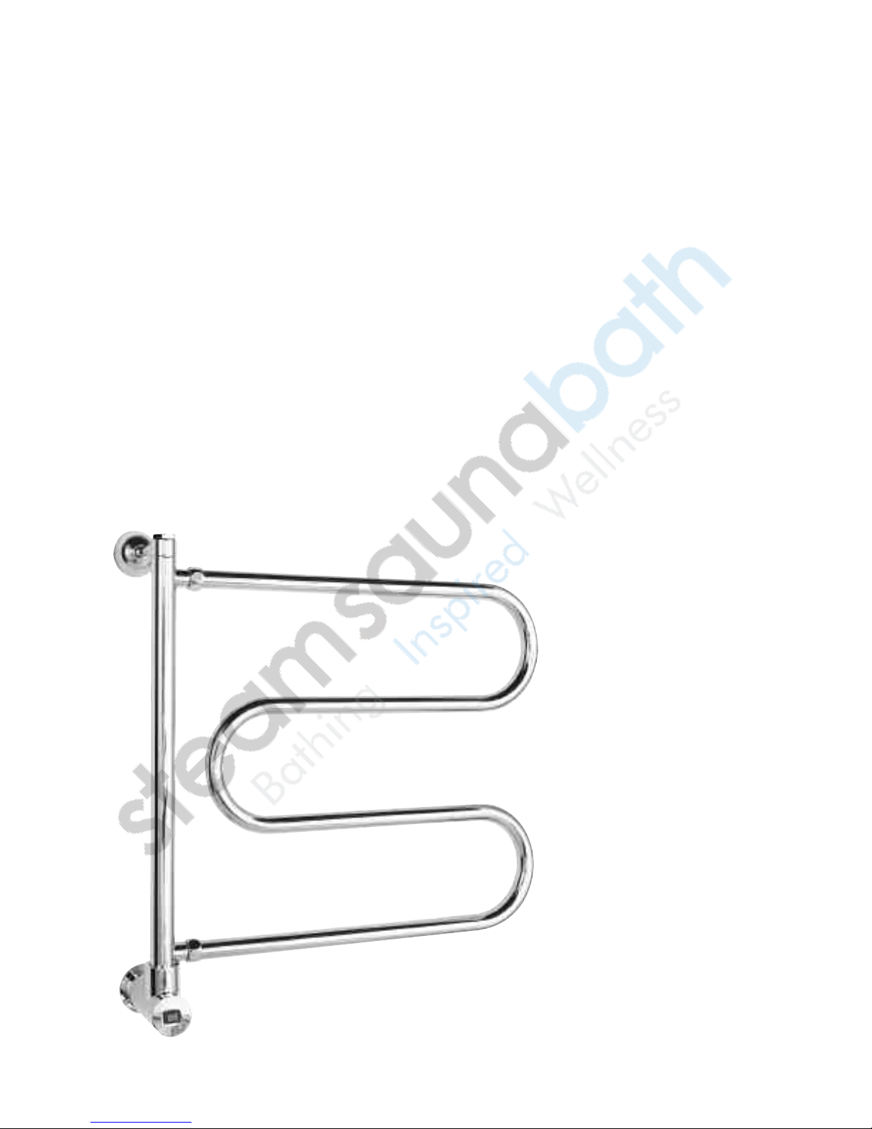
Electric & Hydronic Models
Installation & Operating Instructions
towelwarmers
®
steam
.
mr
Model _________________
Serial #________________
PUR 103852 Rev. 12/09
Page 2
Table of Contents
___________________________
Electric Models . . . . . . . . . . . . . . . . . . . . .1
General Information & Specifications . . . . . . . . . . . . .2
Wall Preparation . . . . . . . . . . . . . . . . . . . . . . . . . . . .3
Mounting Dimensions . . . . . . . . . . . . . . . . . . . . . . . .4
Installation
Models 542, 552, 554, 562, 572, 634, . . . . . . . . . . . .5
Model 842 . . . . . . . . . . . . . . . . . . . . . . . . . . . . . . .6
Models 500 & 510 . . . . . . . . . . . . . . . . . . . . . . . . .7
Model 556 & 856 . . . . . . . . . . . . . . . . . . . . . . . . . .8
Electrical Connections . . . . . . . . . . . . . . . . . . . . . .9-10
Optional Programmable Timer . . . . . . . . . . . . . . . . . .11
____________________________
Hydronic Models . . . . . . . . . . . . . . . . . .12
General Information & Pre-Installation . . . . . . . . . . .13
Wall & Plumbing Preparation . . . . . . . . . . . . . . . . . .14
Installation, Operation & Maintenance . . . . . . . . . . .15
___________________________
towelwarmers
®
IMPORTANT NOTE:
and caution symbols. This blocked information is important for the safe and
efficient installation and operation of this Towel Warmer. These are types of
potential hazards that may occur during this installation and operation:
WARNING
!
CAUTION
!
IMPORTANT NOTE:
This highlights information that is especially relevant to a problem-free installation.
All information in these instructions is based on the latest product information
available at the time of publication. Sussman-Automatic Corporation reserves the
right to make changes at any time without notice.
Sussman-Automatic
Corporation®
[email protected]
www.mrsteam.com
As you follow these instructions, you will notice warning
states a hazard may cause serious injury or death
if precautions are not followed.
signals a situation where minor injury or product damage
may occur if you do not follow instructions.
43-20 34th Street
Long Island City, NY 11101
Tel: 1-800-76 STEAM
Fax: (718) 472-3256 Western
9410 S. La Cienega Blvd.
Inglewood CA 90301
1-800 -72 STEAM
Fax: (310) 216-2944
steam
.
mr
pur 103852 rev 11.1/08
Page 3
mr
.
steam
®
towelwarmers
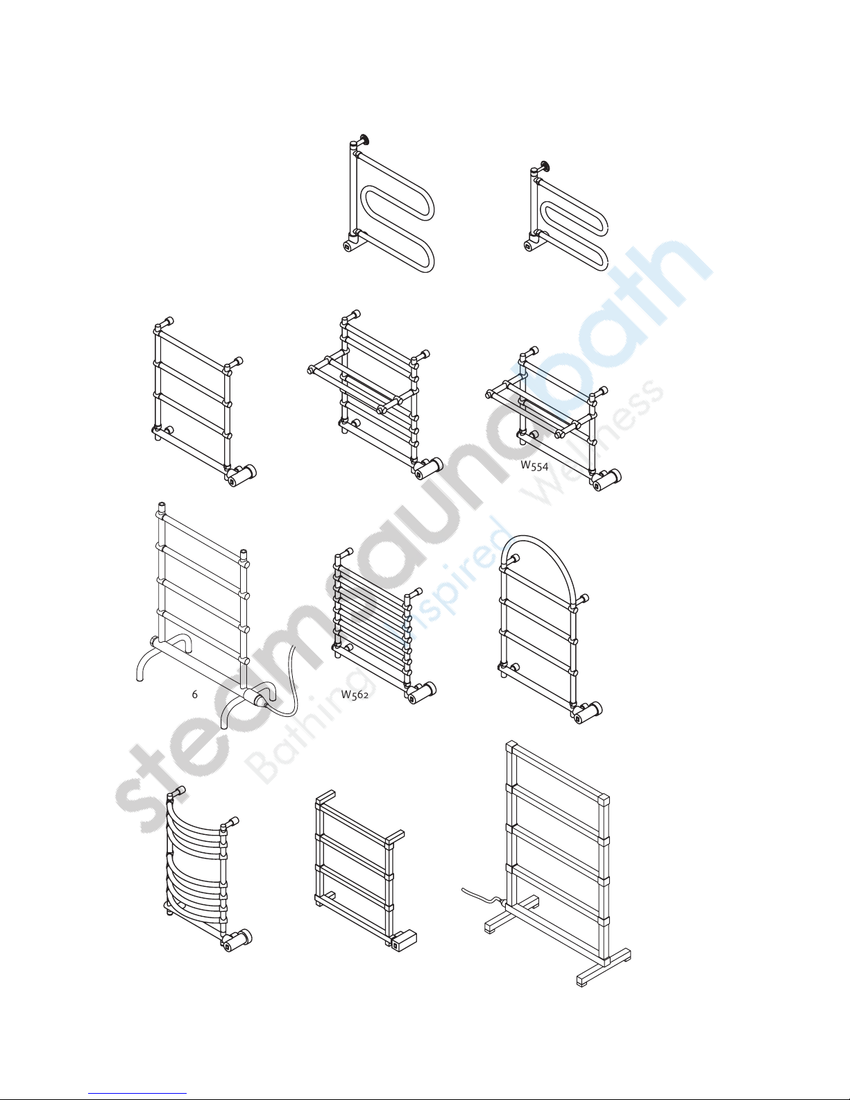
Models W500, W510, W542, W552, W554,
Electric Models
W556, W562, W572, W634, W842, W856
___________________________
Model
___________________________
Serial #
W500 W510
W542 W552 W554
W556 W562 W572
W634 W842 W856
Page 4
mr.steam®towelwarmers Electric Models
_________________________________________________________________
Installation and Operating Instructions
HOMEOWNER:
__________________________________________
THANK YOU for selecting Mr.Steam Towel Warmer, the perfect
addition to bathrooms, family spas, and exercise rooms within
your home. Our products have long been a standard for quality
and comfort, and we are sure that you will experience continued enjoyment from the Towel Warmer you have purchased by
following these simple instructions.
WARNING
!
Warmer is an electrical heating appliance, intended only for
indoor residential applications and, as such, should be
installed and used with certain precautions for your safety.
1. INSTALLATION PROCEDURES FOR PERMANENTLY-WIRED
WALL-MOUNTED UNITS MUST BE ACCOMPLISHED BY
QUALIFIED PERSONNEL IN STRICT ACCORD WITH
APPLICABLE NATIONAL AND LOCAL BUILDING AND
ELECTRICAL CODES.
2. DO NOT place TOWEL WARMER units inside a shower, sauna
or steam room enclosure or any other wet location or with
elevated temperatures.
3. CAUTION is advised when Towel Warmer is accessible to
children.
4. For the ultimate ease in use, a dedicated wall switch or
timer can be used to control the TOWEL WARMER unit.
Contact Mr.Steam for an in-wall 24-hour-7 day timer
(PN W-103588) Note: All switches and control devices must
be installed on the load (black) side of the Towel Warmer
circuit in compliance with the National Electric Code and
Local Codes. (see page 11 for installation instructions)
IMPORTANT:
protected and maintained by an occasional wiping with a soft,
non-abrasive, damp cloth and lightly polished, thereafter, with
a soft dry cloth when the Towel Warmer is cold. Under no circumstances should abrasive cleaning powders, metal polish or
chlorine-based cleaners be used on any part of this product.
IMPORTANT:
in water. Fabrics that contain soap or detergent residue may
show what appears to be scorch marks. However this is simply
the discoloration of the residue. The Towel Warmer unit does
not reach sufficient temperature to scorch fabric. We are not
responsible for discoloring or damage of any fabrics.
TOWEL WARMERS ARE HOT! The Towel
The finish of your Towel Warmer can be
This appliance is intended for towels washed
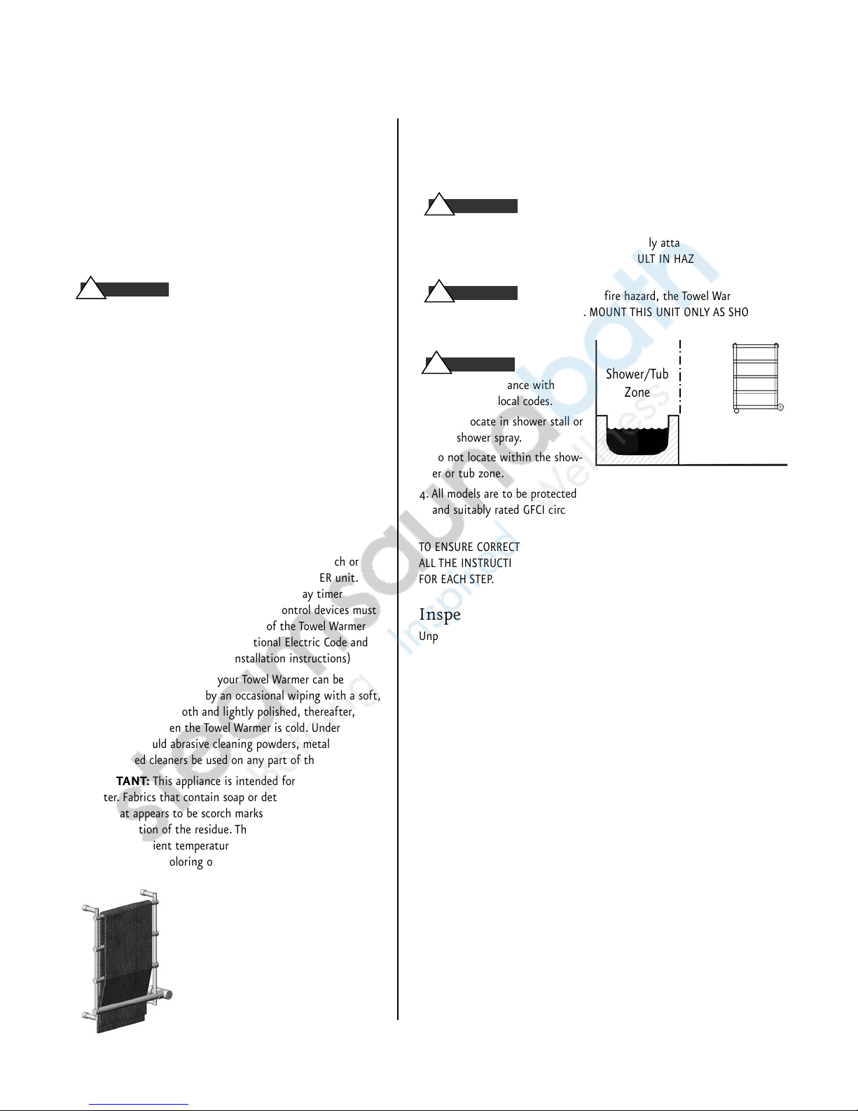
This picture shows the recommend
method of draping a towel on a towel
warmer. Ensure as much as possible of
the towel's surface is touching the
towel warmer to ensure fast even warming of the towel.
INSTALLER:
_________________________________________________________
READ THIS ENTIRE INSTRUCTION MANUAL THOROUGHLY BEFORE BEGINNING
INSTALLATION. LEAVE THESE INSTRUCTIONS WITH HOMEOWNER.
WARNING
!
BEFORE WIRING OR SERVICING YOUR TOWEL WARMER. Follow instructions
to make certain your Towel Warmer is properly attached to the wall. FAILURE TO FOLLOW THESE STEPS COULD RESULT IN HAZARDOUS CONDITIONS.
WARNING
!
remain in its intended position. MOUNT THIS UNIT ONLY AS SHOWN IN
THESE INSTRUCTIONS.
CAUTION
!
1. Install in accordance with
National and local codes.
2. Do not locate in shower stall or
near shower spray.
3. Do not locate within the show-
er or tub zone.
4. All models are to be protected by dedicated
and suitably rated GFCI circuit breaker or equal.
TO ENSURE CORRECT OPERATION OF YOUR TOWEL WARMER, PLEASE FOLLOW
ALL THE INSTRUCTIONS CAREFULLY, OBSERVING THE "CAUTION" NOTATIONS
FOR EACH STEP.
BE CERTAIN ELECTRICITY IS SHUT OFF AT MAIN PANEL
To avoid possible fire hazard, the Towel Warmer must
Shower/Tub
Zone
Do not locate the
towel warmer within
the shower/tub zone
For illustrative purposes only
Inspect Towel Warmer
Unpack the Towel Warmer carefully to avoid any damage or loss of any part.
When opening the box be sure that the parts are not accidentally discarded.
Towel Warmers are shipped in specially designed shipping cartons. The entire
surface of the Towel Warmer is hand-wrapped to protect the finish. It is your
responsibility to immediately inspect for any damage.
TOWEL WARMER SPECIFICATIONS
_____________________________________________________________
Model No. Dimensions (inches) Amps Volts/Phase Weight (lbs.)
_____________________________________________________________
W500 22.5 x 25 x 5 0.83 120/1 20
_____________________________________________________________
W510 20.5 x 18.5 x 5 0.58 120/1 20
_____________________________________________________________
W542 23.75 x 26 x 5.25 1.25 120/1 25
_____________________________________________________________
W552 23.5 x 25.25 x 13 1.67 120/1 40
_____________________________________________________________
W554 23.75 x 21.5 x 13 1.67 120/1 30
_____________________________________________________________
W556 21.75 x 34 x 10 1.25 120/1 25
_____________________________________________________________
W562 23.5 x 23.25 x 5.25 1.67 120/1 30
_____________________________________________________________
W572 23.75 x 36 x 5.25 1.25 120/1 30
_____________________________________________________________
W634 19.5 x 27.5 x 7.25 1.67 120/1 25
_____________________________________________________________
W842 23 x 24.5 x 4.75 0.83 120/1 25
_____________________________________________________________
W856 21.5 x 31 x 9.875 1.25 120/1 30
_____________________________________________________________
W x H x D
2
Page 5
mr.steam®towelwarmers Electric Models
_________________________________________________________________
Installation and Operating Instructions
3
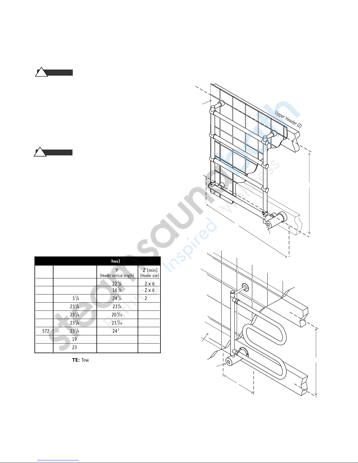
WALL PREPARATION
• DO NOT mount the Towel Warmer without
providing structurally secure headers as shown.
• DO NOT mount the Towel Warmer directly to sheet
rock or any other non-structural surface.
• Use longer fasteners as required if the finished wall surface
prevents adequate mounting with the screws provided.
• Provide a clearance hole in the lower header as required
to route field wiring to the Towel Warmer wiring box.
If a single gang electric box has been roughed-in, install cover plate
PN103877.See part numbers below for decorative finish information.
DO NOT install the Towel Warmer without these instructions.
Cover Plate Part Numbers & Decorative Finishes:
Polished Chrome 103877PC
Polished Brass 103877PB
Polished Nickel 103877PN
Pewter 103877P
Satin Nickel 103877SN
Polished Gold 103877 PG
Satin Gold 103877SG
Antique Brass 103877AB
Oil Rubbed Bronze 103877ORB
IMPORTANT NOTE:
Towel Warmers may have small dimensional
variations and must be measured prior to installation.
For Technical Service Assistance:
East Coast Tel: 1-800-767-8326
West Coast Tel: 1-800-727-8326
!
CAUTION
!
WARNING
MOUNTING DIMENSIONS (inches)
MODEL X(min) Y Z (min)
(Header horizontal length) (Header vertical length) (Header size)
W 500 5 225⁄
8
2 x 6
W 510 5 161⁄8 2 x 6
W 542 231⁄4 243⁄4 2 x 6
W 552 231⁄4 233⁄4 2 x 6
W 554 231⁄4 205⁄16 2 x 6
W 562 231⁄4 233⁄16 2 x 6
W 572 231⁄4 243⁄4 2 x 6
W 634 19 271⁄8 2 x 6
W 842 23 23
1
⁄4 2 x 6
Finished
wall surface
Upper Header (Z)
Y
Lower Header (Z)
X
Wiring
Box
Finished
wall surface
Wiring Box
Upper Header (Z)
Lower Header (Z)
X
Y
Page 6
C
D
B
A
D
Wiring Box
Wiring Box
mr.steam
®
towelwarmers Electric Models
_________________________________________________________________
Installation and Operating Instructions
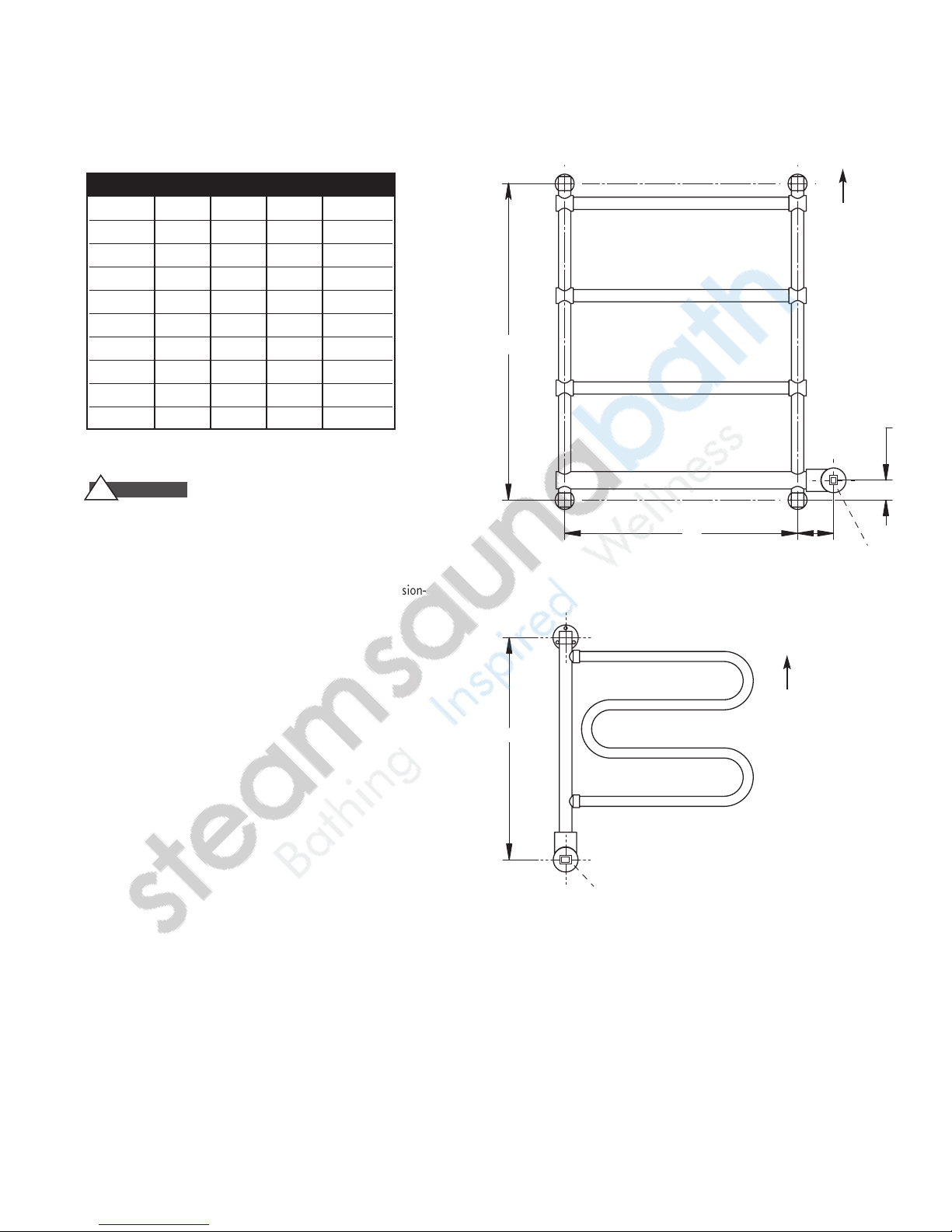
MOUNTING DIMENSIONS (inches)
MODEL ABC D
W 500 ~ ~~ 225⁄
W 510 ~~~161⁄
W 542 11⁄
W 552 11⁄
W 554 11⁄
W 562 11⁄
W 572 11⁄
W 634 11⁄
W 842 11⁄
WA R N I N G
!
23⁄
8
23⁄
8
23⁄
8
23⁄
8
23⁄
8
23⁄
8
21⁄
8
181⁄
4
4
4
4
4
4
4
181⁄
181⁄
181⁄
181⁄
143⁄
181⁄
2
2
2
2
2
16
2
243⁄
233⁄
205⁄
223⁄
243⁄
2611⁄
231⁄
8
8
4
4
16
4
4
16
4
Install Towel Warmers in upright position only. Locate with indicator light on bottom as shown. Failure to install properly may result
in overheating and a hazardous condition.
This
End
Up
IMPORTANT NOTE:
Towel Warmers may have small dimension-
al variations and must be measured prior to installation.
This
End
Up
4
Page 7
mr.steam®towelwarmers Electric Models
_________________________________________________________________
Installation and Operating Instructions
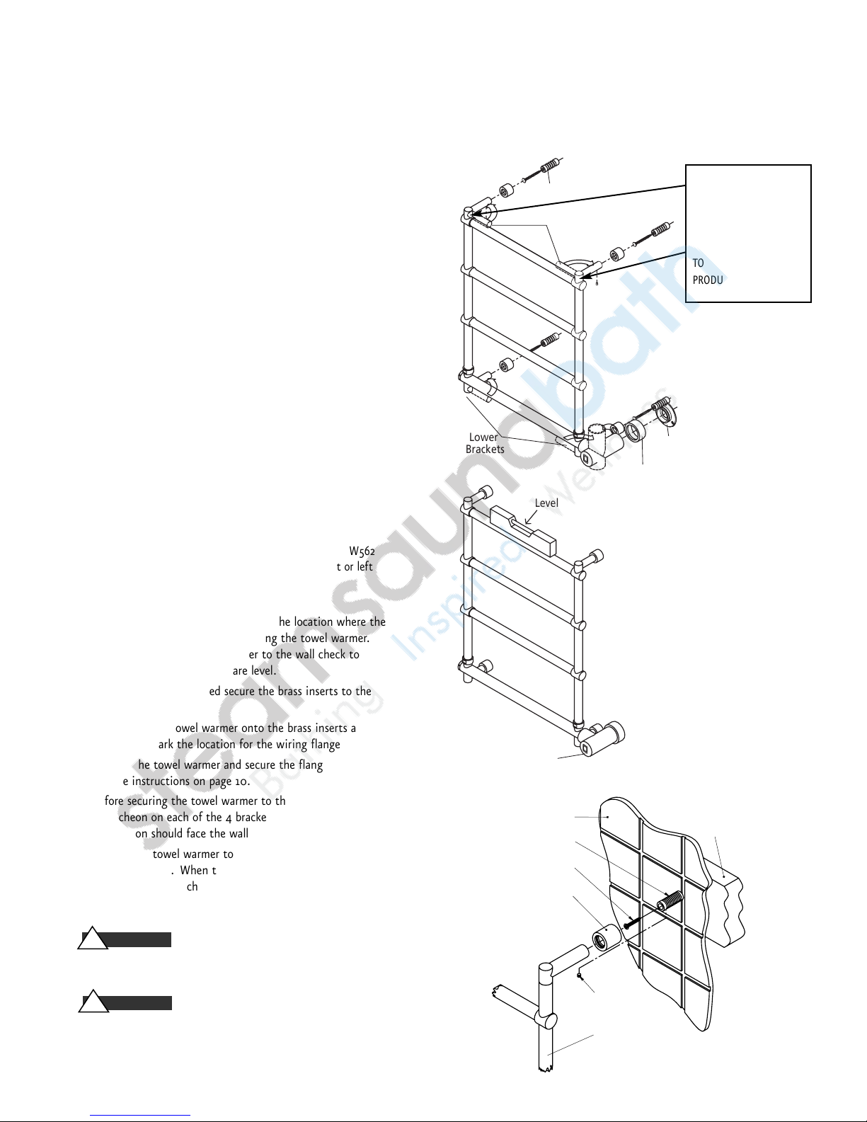
MODELS
W542, W552, W554,
W562, W572, W634
BOX CONTENTS:
• Towel Warmer
• (3) Small Screws
• (4) Bracket Escutcheons • (1) Wire Box Escutcheon
• (4) Large Screw • (4) Bracket Set Screws
• (1) Wiring Box Set Screw • (4) Brass Inserts
• (1) Wire Box Flange • (1) Allen Key
• Warranty • Instruction & Operation Manual
1. Remove Towel Warmer and parts from the packing materials.
2. Rotate the two upper and two lower brackets into position
as shown.
IMPORTANT:
DO NOT LOOSEN SCREWS TO SWIVEL
BRACKETS. LOOSENING SCREWS WILL CAUSE INTERNAL
LIQUID TO ESCAPE AND CAUSE PRODUCT DAMAGE.
3. Using the allen key provided, loosen the wiring
box set screw. DO NOT remove the wiring box.
4. Rotate the wiring box as shown.Tighten the set screw
firmly to prevent the wiring box from rotating.
NOTE:
The wiring box and brackets on models W542, and W562
can be rotated in either direction to result in a right or left
handed wiring box.
5. Measure the towel warmer and mark the location where the
brass inserts will be mounted to hang the towel warmer.
Before securing the towel warmer to the wall check to
ensure the mounting points are level.
6. Using the screws provided secure the brass inserts to the
wall.
7. Gently slide the towel warmer onto the brass inserts as
shown and mark the location for the wiring flange.
8. Remove the towel warmer and secure the flange to the wall
per the instructions on page 10.
9. Before securing the towel warmer to the wall put an
escutcheon on each of the 4 brackets. The open end of the
escutcheon should face the wall as shown.
10. Secure the towel warmer to the brass inserts using the set
screws provided. When the towel warmer is secured to the
wall slide the escutcheons against the wall to hide the
mounting point.
If a single gang electric box has been roughed in See page 3
for instructions.
Install Towel Warmers in upright position only. Locate with
indicator light on bottom as shown. Failure to install properly
may result in a hazardous condition.
IMPORTANT:
DO NOT
LOOSEN SCREWS ON TOP
OR BOTTOM BRACKETS.
LOOSENING SCREWS WILL
CAUSE INTERNAL LIQUID
TO ESCAPE AND CAUSE
PRODUCT DAMAGE.
!
WARNING
!
WARNING
5
Bracket
Escutcheons
Brass Insert
Upper
Brackets
Lower
Brackets
Level
Wiring
Box
Finished surface of wall
Brass Insert
Sliding Escutcheon
Wiring Box
Flange
Wiring Box
Escutcheon
Header
Screw
Set Screw
Towel Warmer
Page 8
mr.steam®towelwarmers Electric Models
_________________________________________________________________
Installation and Operating Instructions
6
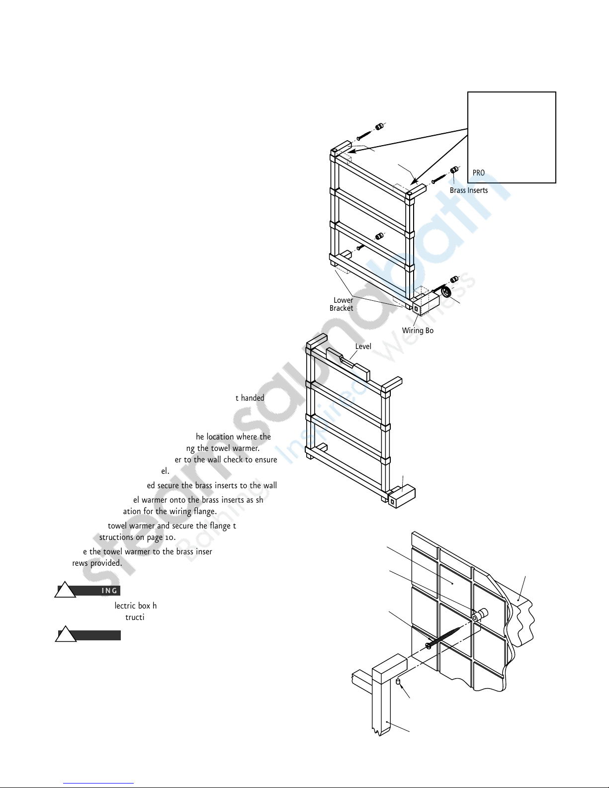
MODEL
W842
BOX CONTENTS:
• Towel Warmer
• (3) Small Screws
• (4) Large Screw • (4) Bracket Set Screws
• (4) Bracket Set Screws • (1) Wiring Box Set Screw
• (4) Brass Inserts • (1) Wire Box Flange
• (1) Allen Key • Warranty
• Instruction & Operation Manual
1. Remove Towel Warmer and parts from the packing materials.
2. Rotate the two upper and two lower brackets into position
as shown.
IMPORTANT:
DO NOT LOOSEN SCREWS TO SWIVEL
BRACKETS. LOOSENING SCREWS WILL CAUSE INTERNAL
LIQUID TO ESCAPE AND CAUSE PRODUCT DAMAGE.
3. Using the allen key provided, loosen the wiring
box set screw.
4. Rotate the wiring box as shown.Tighten the set screw
firmly to prevent the wiring box from backing off.
NOTE:
The wiring box and brackets on model W842 can be
rotated in either direction to result in a right or left handed
wiring box.
5. Measure the towel warmer and mark the location where the
brass inserts will be mounted to hang the towel warmer.
Before securing the towel warmer to the wall check to ensure
the mounting points are level.
6. Using the screws provided secure the brass inserts to the wall.
7. Gently slide the towel warmer onto the brass inserts as shown
and mark the location for the wiring flange.
8. Remove the towel warmer and secure the flange to the wall
per the instructions on page 10.
9. Secure the towel warmer to the brass inserts using the set
screws provided.
If a single gang electric box has been roughed
in See page 3 for instructions.
Install Towel Warmers in upright position only.
Locate with indicator light on bottom as
shown. Failure to install properly may result
in a hazardous condition.
IMPORTANT:
DO NOT
LOOSEN SCREWS ON TOP
OR BOTTOM BRACKETS.
LOOSENING SCREWS WILL
CAUSE INTERNAL LIQUID
TO ESCAPE AND CAUSE
PRODUCT DAMAGE.
!
WARNING
!
WARNING
r
Lower
Bracket
Level
Upper
Brackets
Wiring Box
Brass Inserts
Wiring Box
Flange
Finished surface of wall
Brass Insert
Screw
Wiring
Box
Set Screw
Heade
Towel Warmer
Page 9
mr.steam®towelwarmers Electric Models
_________________________________________________________________
Installation and Operating Instructions
7
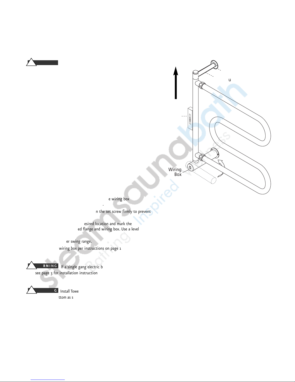
MODELS W500 & W510
TO PREVENT SHOCK HAZARD, BE CERTAIN
THAT ELECTRICITY IS TURNED OFF AT THE MAIN PANEL BEFORE
ANY WIRING IS DONE.
BOX CONTENTS:
• Towel Warmer
• (6) Screws
• (1) Upper Threaded Flange
• (1) Lower Wiring Flange
• (1) Small Allen Key
• (1) Large Allen Key
• Instruction & Operation Manual
• Warranty
1. Remove the Towel Warmer and parts from the packing materials.
2. Rotate the upper bracket as shown.
IMPORTANT:
DO NOT LOOSEN SCREWS TO SWIVEL
BRACKETS. LOOSENING SCREWS WILL CAUSE INTERNAL
LIQUID TO ESCAPE AND CAUSE PRODUCT DAMAGE.
3. Spin on upper threaded flange as shown.
4. Using the smaller allen key provided, loosen the wiring box
set screw. DO NOT remove the wiring box.
5. Rotate the wiring box as shown.Tighten the set screw firmly to prevent
the wiring box from rotating.
6. Place the Towel Warmer in the desired location and mark the
location of the upper threaded flange and wiring box. Use a level to
insure proper alignment.
NOTE:
the Towel Warmer swing range.
7. Mount the lower wiring box per instructions on page 10.
If a single gang electric box has been roughed-in,
then see page 3 for installation instructions.
Install Towel Warmers in upright position only. Locate with
indicator light on bottom as shown. Failure to install properly may result in
overheating and a hazardous condition.
!
WARNING
!
WARNING
!
WARNING
This
End
Up
Upper Threaded Flange
Upper Support Bracket
Level
Wiring
Box
Page 10
mr.steam®towelwarmers Electric Models
_________________________________________________________________
Installation and Operating Instructions
8
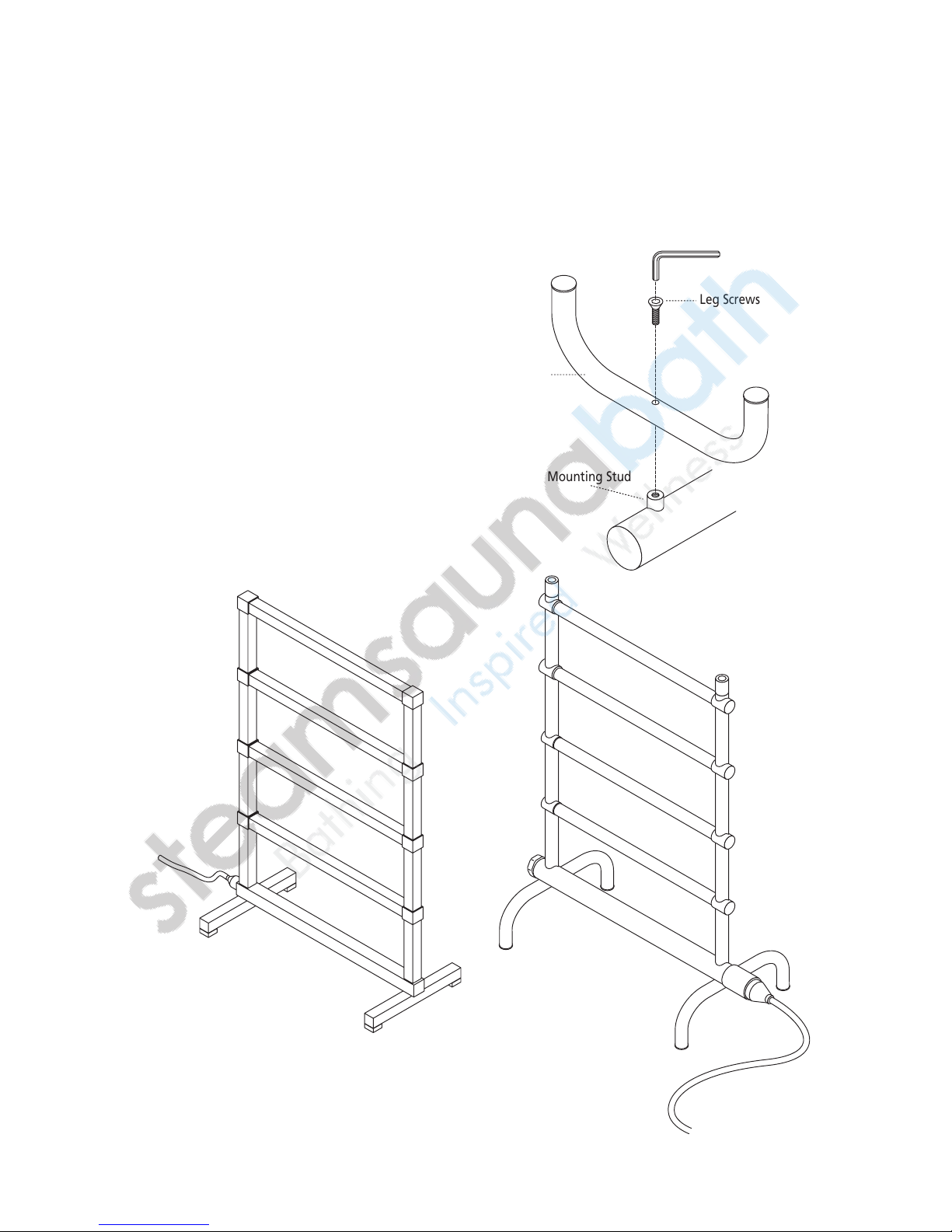
MODELS W556 & W856 IMPORTANT: HAND TIGHTEN ONLY!
BOX CONTENTS:
• Towel Warmer with 7' Grounding Type Power Cord
• (2) Legs
• (2) Leg Screws
• (1) Large Allen Key
• Instruction & Operation Manual
• Warranty
1. With the unit unplugged, assemble the tubular legs
to the bottom of the Towel Warmer as shown.
2. HAND TIGHTEN ONLY!
NOTE: Models W556 & W856 have no ON/OFF switch.
w856 W556
Legs
Leg Screws
Mounting Stud
Page 11
mr.steam®towelwarmers Electric Models
_________________________________________________________________
Installation and Operating Instructions
9
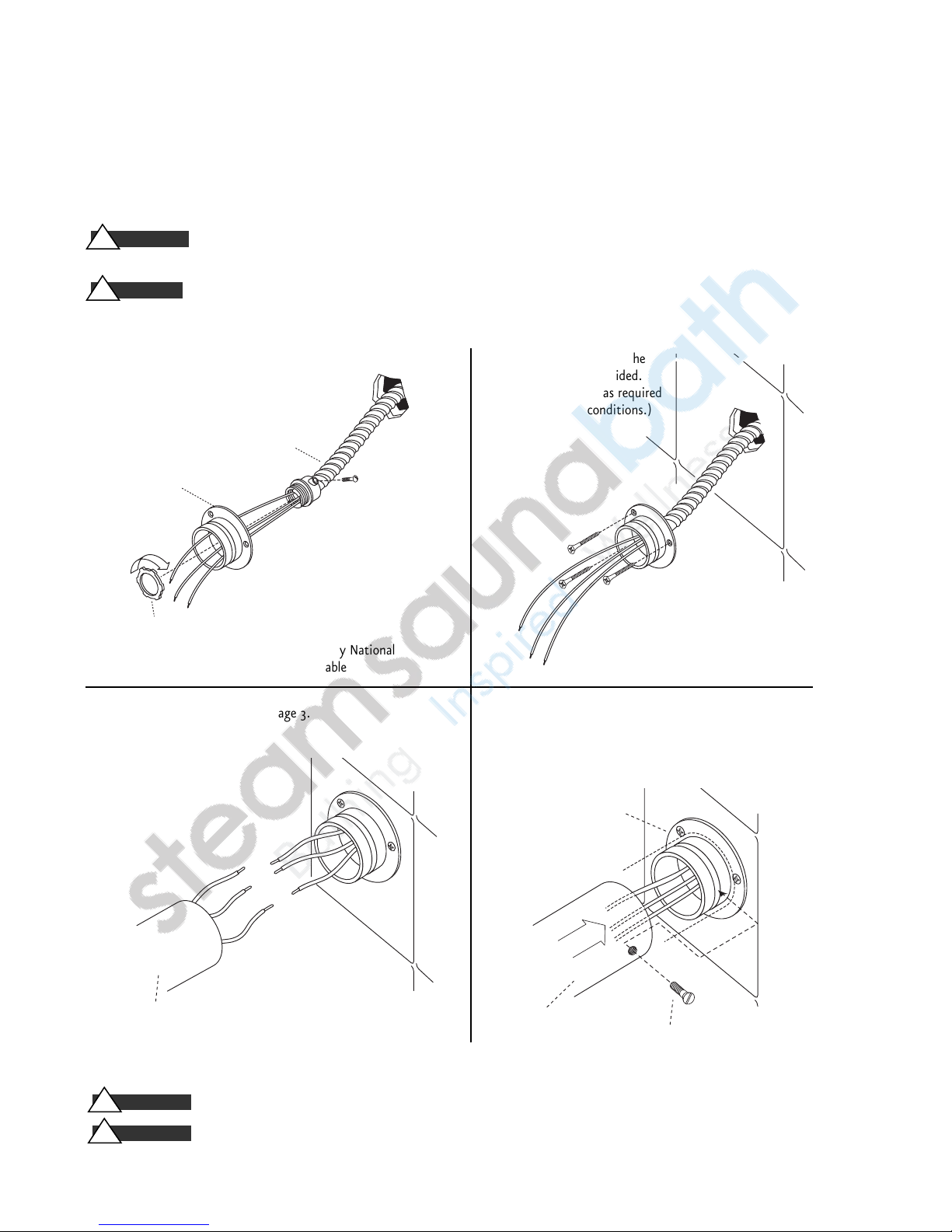
NOTE:
The Towel Warmer wires are color coded:
BLACK for LINE, WHITE for NEUTRAL, GREEN/YELLOW for EQUIPMENT GROUND.
If a single gang electric box has been roughed-in, see page 3 for instructions
Install Towel Warmers in upright position only. Locate with switch on bottom as shown.
Failure to install properly may result in overheating and a hazardous condition.
Wiring Box Set Screw(s)
Wiring Box
Wiring Flange
Wiring Box
Wiring Flange
BX Connector Lock Nut
BX Cable*
(or greenfield)
!
WARNING
!
WARNING
2. Secure wiring flange to the
wall with screws provided.
(Use longer screws as required
by construction conditions.)
4. Slide the wiring box onto the wiring flange and tighten
the set screw firmly. Secure the upper threaded flanges
and lower bracket with screws provided.
ELECTRICAL CONNECTIONS
Models
W500, W510, W542, W552, W554, W562, W572, W634, W842
TO PREVENT SHOCK HAZARD, BE CERTAIN THAT ELECTRICITY IS TURNED OFF AT THE MAIN PANEL BEFORE ANY WIRING IS DONE.
The towel warmer is an electronically operated device. It must be installed by a licensed electrician
in accordance with local code and the National Electric Code (NEC).
Install a wall switch or timer to turn the towel warmer on and off.
NOTE: When the towel warmer is energized, the indicator light on the towel warmer will illuminate.
1. Assemble the BX cable connector to the wiring flange as shown.
NOTE:
NM (non-metallic) cable, if permitted by National
and Local Codes may be used instead of BX cable
3. Connect wiring per instructions page 3.
!
WARNING
!
CAUTION
Page 12
mr.steam®towelwarmers Electric Models
_________________________________________________________________
Installation and Operating Instructions
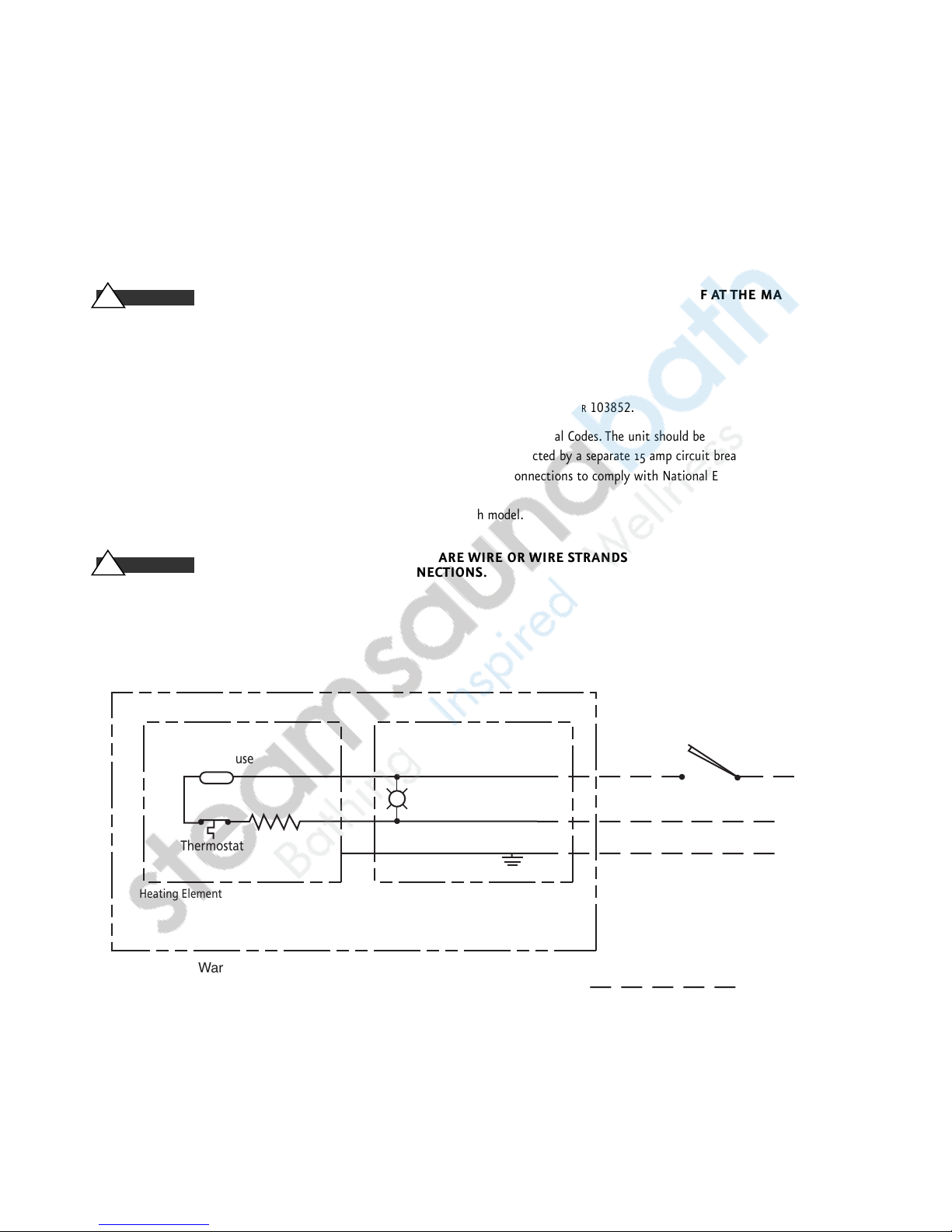
ELECTRICAL SPECIFICATIONS
Field Wired Models:
Plug-in Models: W556, W856
ELECTRICAL CONNECTIONS
W500, W510, W542, W552, W554, W562, W572, W634,W842
WARNING
!
TO PREVENT SHOCK HAZARD, BE CERTAIN THAT ELECTRICITY IS TURNED OFF AT THE MAIN PANEL
BEFORE ANY WIRING IS DONE.
All wiring must conform to National Electrical and Local Codes.
GENERAL:
The Towel Warmer requires 120VAC, 60 Hz power supply.
Specific amperage needed is listed in the Towel Warmer Specifications Chart on page 2 of
PUR
103852.
A. Electrical connections should be made as prescribed by the National Electric and Local Codes.The unit should be
field wired using 14 AWG min 90°C-rated copper wire. All models are to be protected by a separate 15 amp circuit breaker or equal.
B. Make connections between Towel Warmer and house wiring using approved connections to comply with National Electrical Local Codes.
LINE (black), NEUTRAL (white), and GROUND.
C. Install the Towel Warmer according to the specific instructions for each model.
WARNING
!
TO PREVENT SHOCK HAZARD, NO BARE WIRE OR WIRE STRANDS SHOULD
BE VISIBLE AFTER MAKING CONNECTIONS.
Thermal Fuse
Indicator Light
Thermostat
N
GRND
L
X
X
X
Field Installed Wall Switch or
Mr. Steam Digital Programmable Timer
PN: 103588DIG
L
N
GRND
Heating Element Wiring Box
Electric Towel Warmer
Field Wiring
10
Page 13
mr.steam®towelwarmers Electric Models
_________________________________________________________________
Installation and Operating Instructions
11
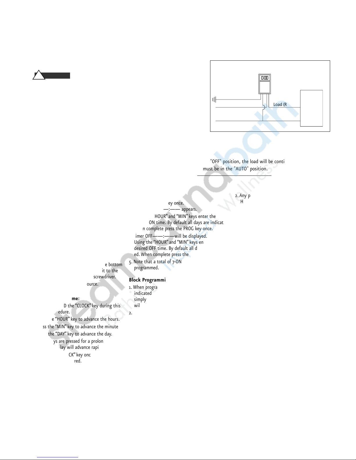
OPTIONAL DIGITAL PROGRAMMABLE TIMER
Installation: To The Installer
1. Read the operating instructions provided with the timer.
2. Disconnect power supply prior to installation to prevent electrical shock.
3. Damage to the contacts caused by short circuiting will void the warranty.
4. Wire in accordance with National Electrical and Local Code requirements.
Be sure all connections are secure. Double check all twist-on wire connectors.
5. Mount timer into wall box using supplied screws.
6. If timer does not operate, check that the timer's black wire is connected to
hot line and not the load. If necessary, reverse connections to red and black wires
7. When the indicator light on the towel warmer is illuminated, the towel warmer is energized.
MANUAL OPERATION
The slide switch provides manual operation of the load, overriding the timer, Set to the "OFF" position, the load will be continuously off, and if set
to "ON", it will be continuously on. For automatic timed ON's and OFF's, the switch must be in the "AUTO" position.
____________________________________________________________________________________________________________
PROGRAMMING
!
WARNING
WIRING DIAGRAM
OPTIONAL DECORATIVE FACEPLATE FOR TIMER:
Polished Chrome 103872D-PC Polished Nickel 103872D-PN Polished Gold 103872D-PG Pewter 103872D-P
Polished Brass 103872D-PB Brushed Nickel 103872D-BN Satin Gold 103872D-SG
Antique Brass 103872D-AB Satin Nickel 103872D-SN Oil Rubbed Bronze 103872D-ORB
Power-Up Sequence:
1. Lift up the bottom of the door using a small
slotted screwdriver.
2. Position the slide switch to TIMER.
3. Press the "RESET" button using a paper clip.
4. The display should flash 12:00AM on
Monday.
In the event that the screen is blank,
check the following:
1. The OFF/TIMER switch located at the bottom
may be in the OFF position. Slide it to the
TIMER position using a small screwdriver.
2. Check the 120VAC power source.
Setting Current Time:
1. Press and HOLD the “CLOCK” key during this
entire procedure.
2. Press the “HOUR” key to advance the hours.
3. Press the “MIN” key to advance the minutes.
4. Press the “DAY” key to advance the day.
5. If any keys are pressed for a prolonged peri-
od, the display will advance rapidly.
6. Release the “CLOCK” key once the time and
day have been entered. Now the timer is in
operation and ready to be programmed. The
colon “:”after the hours will continuously
flash indicating that the time is advancing.
Programming:
1. Press the “PROG” key once.
TIMER 1 ON ——:—— appears.
2. Using the “HOUR” and “MIN” keys enter the
desired ON time. By default all days are indicated.
When complete press the PROG key once.
3. Timer OFF——:——will be displayed.
Using the “HOUR”and “MIN” keys enter the
desired OFF time. By default all days are indicated. When complete press the PROG key once.
5. Note that a total of 7-ON and 7-OFF events can be
programmed.
Block Programming:
1. When programming ON/OFF events, all days are
indicated by default. To change the day selection
simply keep pressing the Day key and the display
will change as follows:
2. Individual Day (MON, TUE, etc.)
3. MON~FRI; SAT~SUN; MON~SAT; MON~SUN
4. MON-WED-FRI; TUE-THU-SAT
5. MON~WED; THU~SAT
6. Follow the steps above to complete programming.
Reviewing Programs:
1. To review the programs that have been entered
simply press and release the PROG key. Each time
you do this you will be able to scroll thru the
programs.
2. Any program can be edited simply by pressing the
HOUR, MIN, and DAY keys.Then press the PROG
key in order to accept the changes.
3. When complete press the “CLOCK” key to return
to current time and day.
Deleting Programs:
1. To delete a particular program simply press the PROG
key until the desired program is displayed.
2. Then press the HOUR and MIN keys until --:--is displayed. Then press the PROG key in order to delete
this particular program. 3. When complete press the
“Clock” key to return to current time and day.
Manual Override:
Pressing the timer cover (when closed) will alternate
the unit ON or OFF.
Initial Startup:
When you initially program the unit it may be necessary to press the manual override key as the unit will
not look back to determine if it should be ON. For
example if the current time is 2:00PM and you just programmed the unit to turn ON at 1:00PM, you will need
to press the manual override key to turn it ON.
Thereafter, the unit will resume normal operation
(automatic). MEMORY BACKUP: The timer is equipped
with a rechargeable Ni-Mh battery which will protect
your programs during power failure for up to 30 days.
No need to replace battery. Note that the screen blanks
during a power failure.
Ground (GRN/YEL)
Line (Black) Load (RED) Towel
Warmer
Neutral (White)
Page 14
12
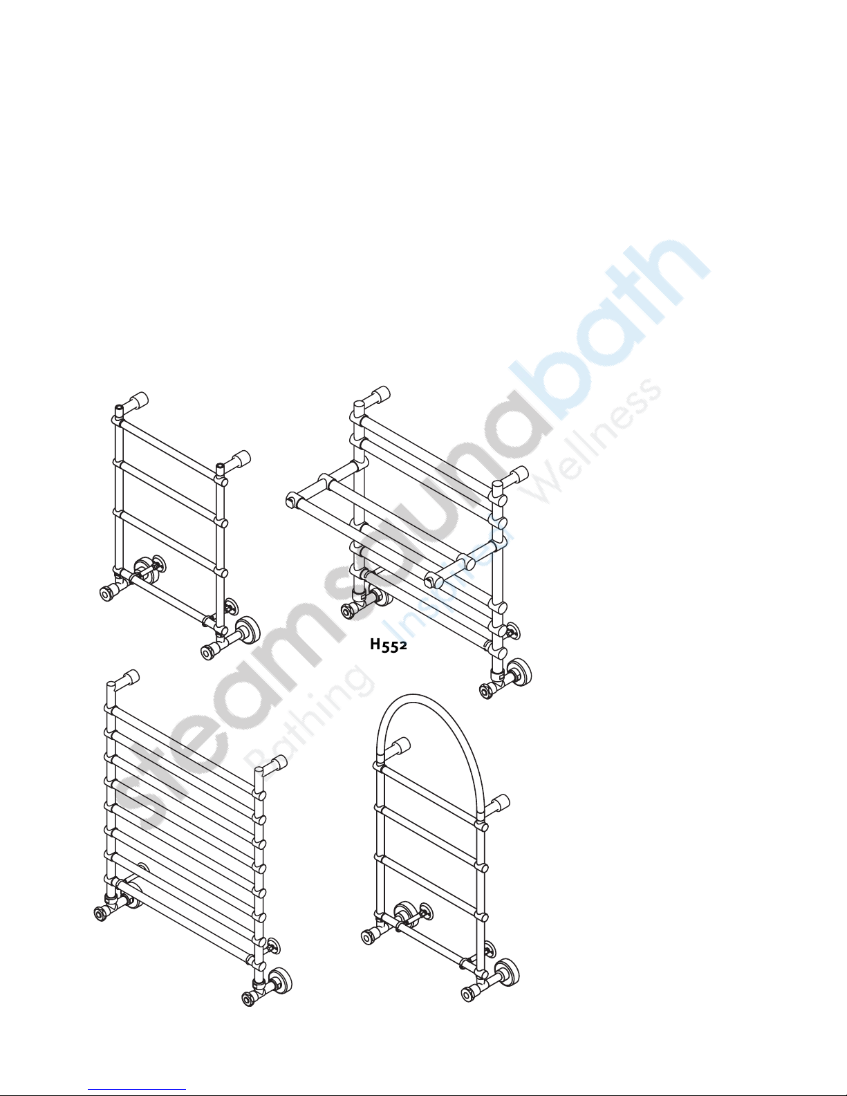
H542 H552
H562 H572
mr
.
steam
®
towelwarmers
Hydronic Models
Models H542, H552, H562, H572
Model __________________________
Serial #__________________________
Page 15
mr.steam®towelwarmers Hydronic Models
_________________________________________________________________
Installation and Operating Instructions
13
Suitable only for closed loop non-potable hot
water systems. Tighten Towel Warmer unions only. Do not turn
valves as leaking may result
Do not use with water over 158 degrees F. (7o˚
C) Do not use with steam. Using with steam or water over 158
degrees F or 20 psig, may result in scalding or hazardous conditions.
1.
Read this entire instruction manual thoroughly before beginning
installation and save these instructions.
2.
Follow instructions accurately to make certain the Towel Warmer
is properly attached to the wall. FAILURE TO FOLLOW THESE
STEPS COULD RESULT IN PROBLEMS.
3.
Do not use an abrasive cleaner on the Towel Warmer. A mild deter-
gent will clean and restore most units to their original beauty.
4.
TO ENSURE FULL EFFICIENCY OF YOUR TOWEL WARMER, PLEASE
FOLLOW ALL THE INSTRUCTIONS CAREFULLY, OBSERVING THE
“CAUTION” NOTATIONS FOR EACH STEP.
5.
Inlet water temperature should be between 120°F and 158°F.
DO NOT exceed this limit. A burn hazard may result.
GENERAL:
Most Towel Warmers provide enough heat to warm towels and pro-
vide supplemental heat to the room. Larger units may be sufficient
to serve as the sole heat source for a small bathroom.
Optional Brackets
Additional towel warmer support brackets are available for installations where plumbing does not provide a rigid support to secure the
towel warmer to the wall.
Bracket Part Numbers and Optional Finishes
Polished Chrome 103959PC Polished Gold 103959PG
Polished Brass 103959PB Satin Gold 103959SG
Polished Nickel 103959PN Antique Brass 103959AB
Pewter 103959P Oil Rubbed Bronze 103959ORB
Satin Nickel 103959SN
CAUTION
!
WARNING
!
WARNING
!
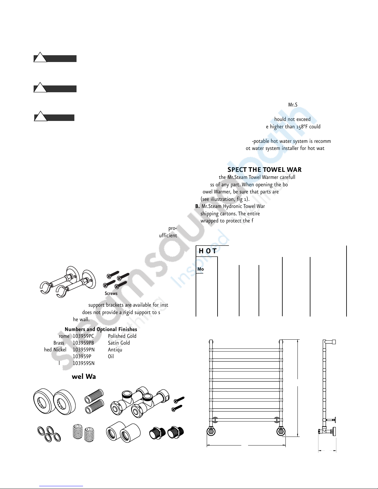
Fig. 1 Towel Warmer Installation Parts
_________________________________________
HOT WATER TOWEL WARMERS
_________________________________________
Dimensions (inches)
__________________
Model H W D BTU/hr†Weight (lbs.)*
_________________________________________
H542
297⁄16
21 5 500 20
________________________________________
H552 25
13
⁄16
21 13 800 30
_________________________________________
H562 24
1
⁄16
21 5 900 30
_________________________________________
H572 38
1
⁄2
21 5 650 20
_________________________________________
†
At 158˚ F *
without water
H
W
D
STEP 1: PRE-INSTALLATION
A.
Select Installation Site: Make certain there is ample clearance on both
sides and back of the Towel Warmer.
NOTE:
This unit is supplied with the proper hardware for installation.
Be sure wall construction is appropriate for hanging (see Step 3A).
B.
Before beginning the installation of any Mr.Steam Hydronic Towel
Warmer, please note the following:
1.
Maximum operating temperature should not exceed 158°F.
Any working water temperature higher than 158°F could create
a potential burn hazard.
NOTE:
A closed loop non-potable hot water system is recommended.
Consult an authorized hot water system installer for hot water system
types.
STEP 2: INSPECT THE TOWEL WARMER
A.
Unpack the Mr.Steam Towel Warmer carefully to avoid any damage
or loss of any part. When opening the box and unwrapping the
Towel Warmer, be sure that parts are not accidentally discarded
(see illustration, fig 1).
B.
Mr.Steam Hydronic Towel Warmers are shipped in specially designed
shipping cartons. The entire surface of the Towel Warmer is handwrapped to protect the finish. Check the for any sign of damage.
Screws
Escutcheons Brass Inserts Valves Screws
Washers Set Screws Mounting Backet Escutcheons Eccentric Coupling
Page 16
14
mr.steam®towelwarmers Hydronic Models
_________________________________________________________________
Installation and Operating Instructions
WALL PREPARATION
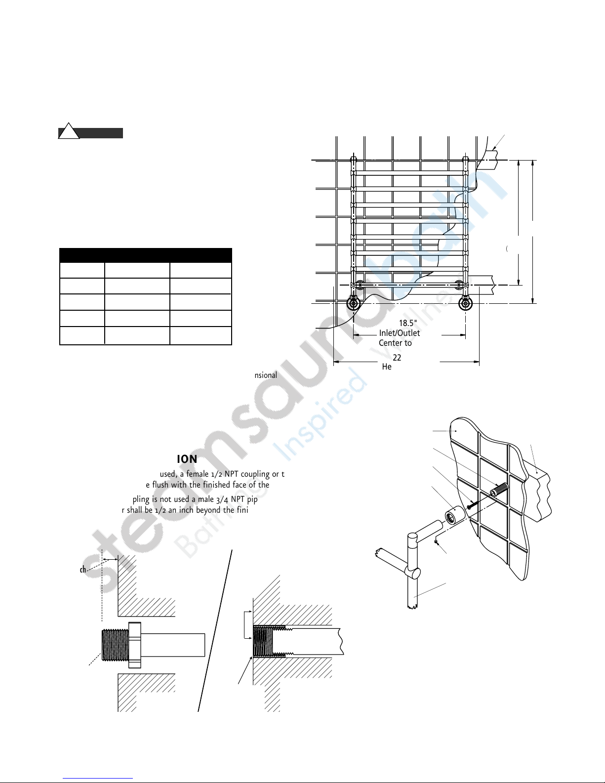
• DO NOT mount the Towel Warmer without providing
structurally secure headers as shown.
• DO NOT mount the Towel Warmer directly to sheet rock
or any other non-structural surface.
• Use longer fasteners as required if the finished wall surface
prevents adequate mounting with the screws provided.
• The recommended location for the optional lower brackets is
on the bottom most rung of the Towel Warmer as shown.
*Inlet/outlet pipe to be 181⁄2" apart for all models
IMPORTANT NOTE:
Towel Warmers may have small dimensional
variations and must be measured prior to installation.
For Technical Service Assistance:
East Coast Tel: 1-800-767-8326
West Coast Tel: 1-800-727-8326
PLUMBING PREPARATION
• If the eccentric coupling is used, a female 1/2 NPT coupling or thread-tosweat adapter should be flush with the finished face of the wall.
• If the eccentric coupling is not used a male 3/4 NPT pipe, coupling or thread
to sweat adapter shall be 1/2 an inch beyond the finished face of the wall.
CAUTION
!
MOUNTING DIMENSIONS (inches)*
MODEL Y1 Y2
H 542 26
7
⁄
16
227⁄
16
H 552 2213⁄
16
1813⁄
16
H 562 211⁄
16
171⁄
16
H 572 267⁄
16
227⁄
16
1/2 inch
3/4 NPT
(Eccentric
Coupling
not used)
Flush
1/2 NPT Coupling
or thread-to-sweat
adapter to be flush
with finished face
of wall.
18.5"
Inlet/Outlet Pipe
Center to Center
22" Min
Header Length
Finished surface of wall
Brass Insert
Screw
Sliding Escutcheon
Minimum Header
Size 2" x 6"
Y1
Y2
(optional)
Header
Set Screw
Towel Warmer
Page 17
mr.steam®towelwarmers Hydronic Models
_________________________________________________________________
Installation and Operating Instructions
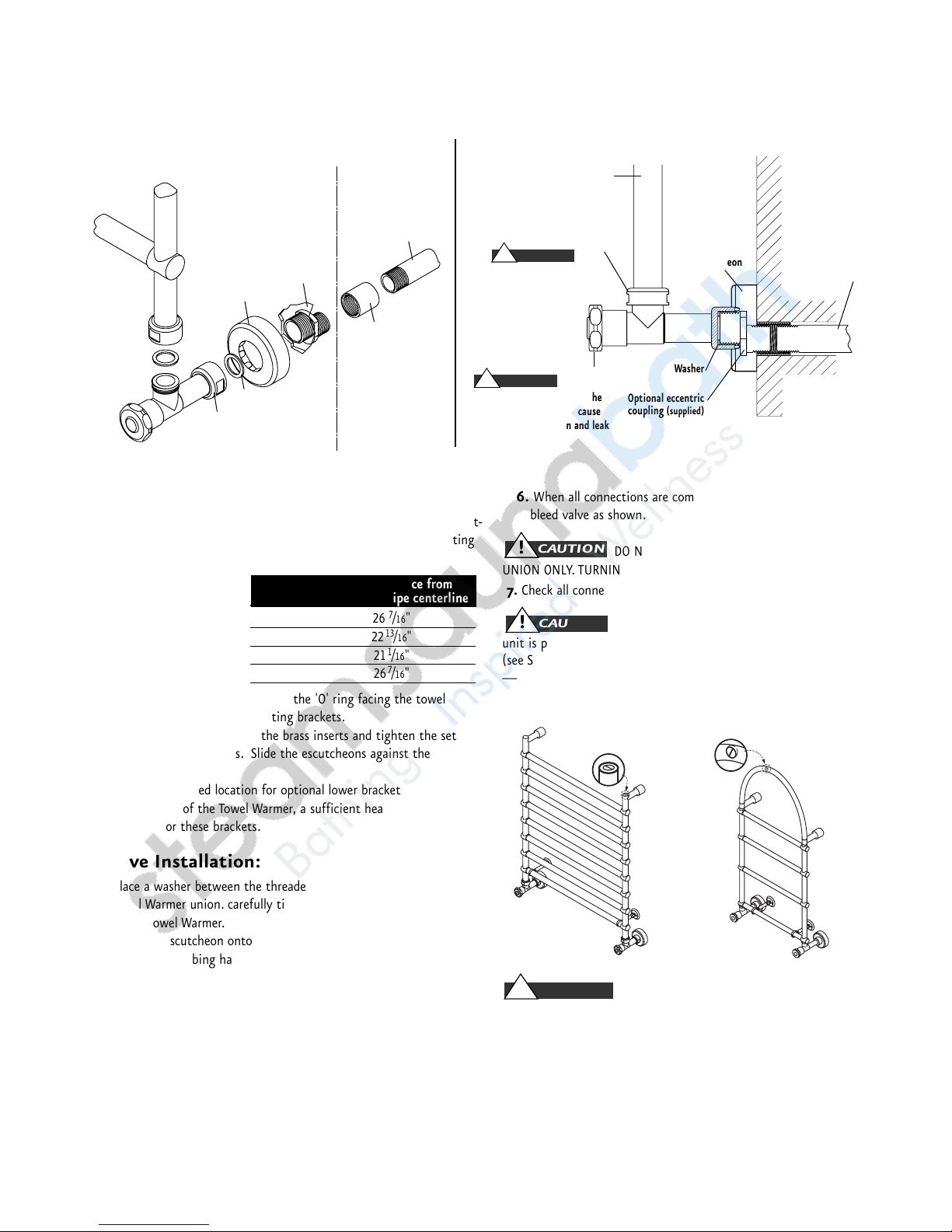
6.
When all connections are complete, vent the unit using the
bleed valve as shown.
DO NOT TURN THE VALVE BODY, TURN THE
UNION ONLY. TURNING THE VALVE MAY RESULT IN LEAKS
7.
Check all connections for leaks.
DO NOT open the bleed screw when the
unit is pressurized as hot water may present a scalding hazard.
(see Step 6 in installation)
___________________________________________________
Bleed screw location for Bleed screw location
models H542, H552, H562 for model H572
Make sure the bleed screw is securely
tightened and not leaking.
STEP 4: OPERATION & MAINTENANCE
CLEANING:
The finish of your Mr.Steam Towel Warmer can be
protected and maintained by an occasional wiping with a damp cloth
and lightly polished thereafter with a soft dry cloth. Under no
circumstances should abrasive cleaning powders or metal polish be
used on any part of a chrome or gold plated Towel Warmer.
A.Mounting:
1.
The Mr.Steam Towel Warmer has been designed with integral mount-
ing brackets. These will facilitate a permanent and secure mounting
of the Towel Warmer to the wall using the screws provided.
2.
Locate the brass inserts
according to the
following chart:
(All inlet/outlet pipes
are 18
1
/2" apart.)
3.
Slide a bracket escutcheon (with the 'O' ring facing the towel
warmer) on each of the mounting brackets.
4.
Slide the towel warmer on the brass inserts and tighten the set
screws on both brackets. Slide the escutcheons against the wall to
hide the joint.
5.
The recommended location for optional lower brackets is on the
bottom rung of the Towel Warmer, a sufficient header should be
provided for these brackets.
B. Valve Installation:
1.
Place a washer between the threaded portion of the valve and the
Towel Warmer union. carefully tighten the union to secure the valve
to the Towel Warmer.
2.
Slide the escutcheon onto the valve over the valve union.
3.
After the plumbing has been prepared as described place a washer
between the valve union and coupling. Carefully tighten the union to
connect the valve to the plumbing.
4.
Slide the escutcheon over the valve union to cover the inlet and out-
let plumbing.
IMPORTANT:
There are two valves which come with Mr.Steam Hydronic
Towel Warmers. One valve should always be left open, the other valve can
be opened or closed. These valves seal only in the fully open (turn valve
handle counter clockwise) or full closed (turn valve handle clockwise) position. Using the valve to throttle the water flow will result in a leak at the
valve stem.
CAUTION
!
WARNING
!
CAUTION
!
Finished
face of wall
Escutcheon
Upright tube
Union
Turn this union only
to assemble the valve
to the upright tube
Hydronic
Towel Warmer
Towel warmer
union
Washer
Valve
Supplied with
Towel Warmer
Field Supplied
Eccentric
coupling
(optional)
Straight
coupling
(or similar)
Field
Plumbing
Escutcheon
Washer
Valve Union
1/2" Pipe
(field supplied)
Washer
Valve
Optional eccentric
coupling (supplied)
Do not spin this valve onto the
upright tube as this may cause
upright joints to loosen and leak
WARNING
!
HYDRONIC HOOK-UP VALVE INSTALLATION
WARNING
!
15
STEP 3: INSTALLATION
Vertical Distance from
Model Inlet/Outlet pipe centerline
H542
267⁄16
"
H552
2213⁄16
"
H562
211⁄16
"
H572
267⁄16
"
Page 18

mr.steam
Sussman-Automatic
Corporation
[email protected]
www.mrsteam.com
®
®
43-20 34th Street
Long Island City,
TEL: 800 76 STEAM
FAX: 718 472 3256
NY 11101
9410 S. La Cienega Blvd.
Inglewood CA 90301
TEL: 800 72 STEAM
FAX: 310 216 2944
© 2008 Sussman-Automatic Corporation
MR. STEAM and des., A LIFETIME OF PLEASURE, ALLEGRO, AROMAFLO, AUTOFLUSH, CLEAN STEAM...EVERY TIME,
MRSAUNA, STEAM ON DEMAND, STEAM@HOME, SUSSMAN, SUSSMAN LIFESTYLE GROUP, TEMPO, TEMPO/PLUS,
TEMPO/REMOTE, TEMPO/EXT and WARMATOWEL, are registered trademarks of Sussman-Automatic Corporation.
AROMASTEAM, CHROMASTEAM, F1 PLUS, and SAUNA/ONE are trademarks of Sussman-Automatic Corporation.
PUR 103852 Rev. 11.1/08
 Loading...