

Page 1
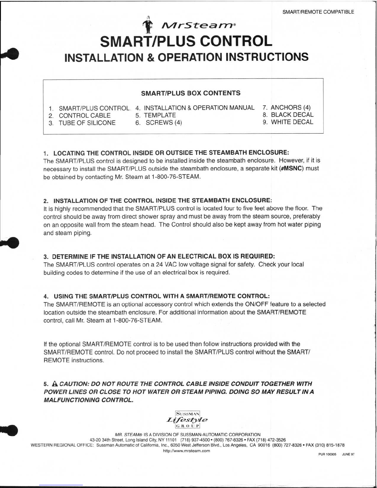
SMART/PLUS BOX CONTENTS
1.
SMART/PLUS CONTROL
4. INSTALLATION & OPERATION MANUAL
7. ANCHORS (4)
2.
CONTROL CABLE
5. TEMPLATE
8. BLACK DECAL
3.
TUBE OF SILICONE
6.
SCREWS (4)
9. WHITE DECAL
SMART/REMOTE COMPATIBLE
ir An r
-
Stea m®
SMART/PLUS CONTROL
INSTALLATION & OPERATION INSTRUCTIONS
1.
LOCATING THE CONTROL INSIDE OR OUTSIDE THE STEAMBATH ENCLOSURE:
The SMART/PLUS control is designed to be installed inside the steambath enclosure. However, if it is
necessary to install the SMART/PLUS outside the steambath enclosure, a separate kit (#MSNC) must
be obtained by contacting Mr. Steam at 1-800-76-STEAM.
2.
INSTALLATION OF THE CONTROL INSIDE THE STEAMBATH ENCLOSURE:
It is highly recommended that the SMART/PLUS control is located four to five feet above the floor. The
control should be away from direct shower spray and must be away from the steam source, preferably
on an opposite wall from the steam head. The Control should also be kept away from hot water piping
and steam piping.
3.
DETERMINE IF THE INSTALLATION OF AN ELECTRICAL BOX IS REQUIRED:
The SMART/PLUS control operates on a 24 VAC low voltage signal for safety. Check your local
building codes to determine if the use of an electrical box is required.
4.
USING THE SMART/PLUS CONTROL WITH A SMART/REMOTE CONTROL:
The SMART/REMOTE is an optional accessory control which extends the ON/OFF feature to a selected
location outside the steambath enclosure. For additional information about the SMART/REMOTE
control, call Mr. Steam at 1-800-76-STEAM.
If the optional SMART/REMOTE control is to be used then follow instructions provided with the
SMART/REMOTE control. Do not proceed to install the SMART/PLUS control without the SMART/
REMOTE instructions.
5.
A
CAUTION: DO NOT ROUTE THE CONTROL CABLE INSIDE CONDUIT TOGETHER WITH
POWER LINES OR CLOSE TO HOT WATER OR STEAM PIPING. DOING SO MAY RESULT IN A
MALFUNCTIONING CONTROL.
SUSSMANI
ffe
.
SZIYI&'
IC
It 0
MR. STEAM
IS A DIVISION OF SUSSMAN-AUTOMATIC CORPORATION
43-20 34th Street. Long Island City, NY 11101 (718) 937-4500 • (800) 767-8326 • FAX (718) 472-3526
WESTERN REGIONAL OFFICE: Sussman Automatic of California, Inc., 6050 West Jefferson Blvd., Los Angeles, CA 90016 (800) 727-8326 • FAX (310) 815-1878
http://www.mrsteam.com
PUR 100305 JUNE 97
Page 2
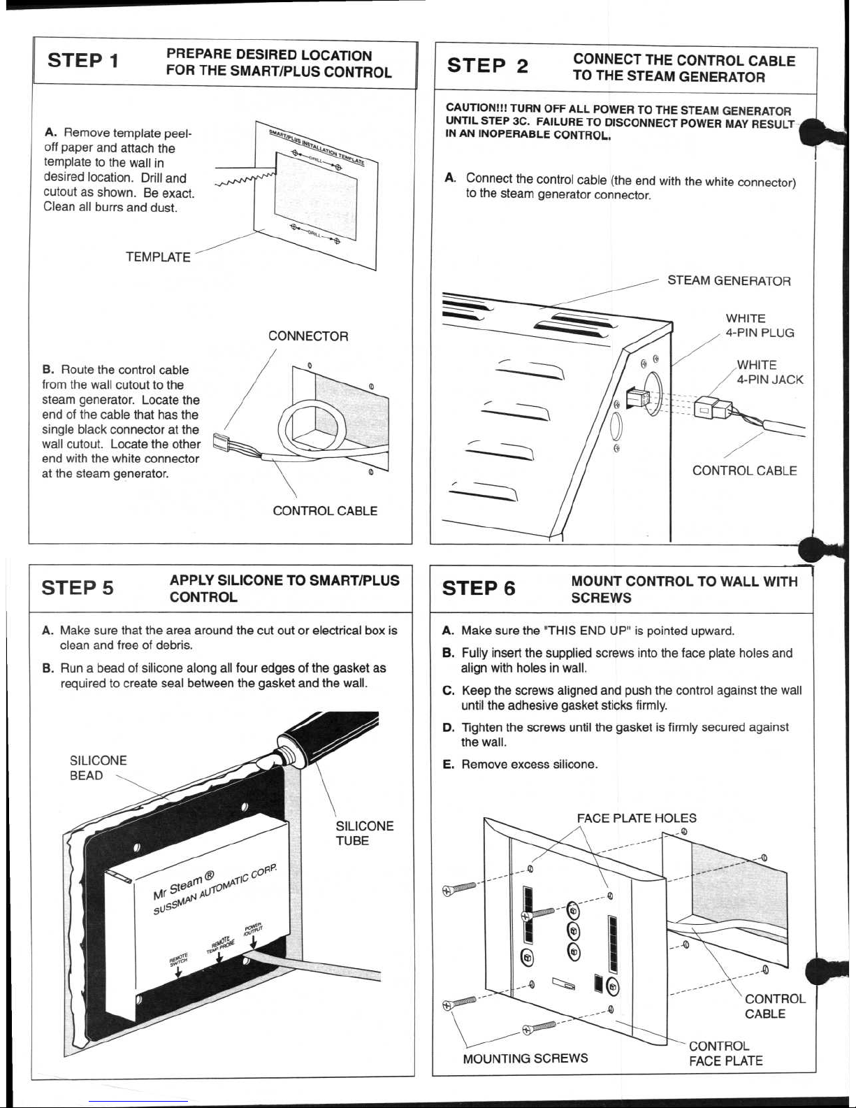
STEP 1
PREPARE DESIRED LOCATION
FOR THE SMART/PLUS CONTROL
STEP 5
APPLY SILICONE TO SMART/PLUS
CONTROL
A.
Remove template peeloff paper and attach the
template to the wall in
desired location. Drill and
cutout as shown. Be exact.
Clean all burrs and dust.
TEMPLATE
CONNECTOR
B.
Route the control cable
from the wall cutout to the
steam generator. Locate the
end of the cable that has the
single black connector at the
wall cutout. Locate the other
end with the white connector
at the steam generator.
CONTROL CABLE
A.
Make sure that the area around the cut out or electrical box is
clean and free of debris.
B.
Run a bead of silicone along all four edges of the gasket as
required to create seal between the gasket and the wall.
SILICONE
BEAD
SILICONE
TUBE
STEP 2
CONNECT THE CONTROL CABLE
TO THE STEAM GENERATOR
CAUTION!!! TURN OFF ALL POWER
UNTIL STEP 3C. FAILURE TO DISCONNECT
IN AN INOPERABLE CONTROL.
A.
Connect the control cable (the
to the steam generator connector.
...._,
---
Th
-
-
Th
,••0
TO THE
end with
the
STEAM
STEAM
POWER
GENERATOR
MAY RESULT
white connector)
GENERATOR
WHITE
4-PIN PLUG
WHITE
4-PIN JACK
re--
CONTROL CABLE
STEP 6
MOUNT CONTROL TO WALL WITH
SCREWS
A.
Make
B.
Fully
align
C.
Keep
until
D.
Tighten
the
E.
Remove
t
o
91
,
v
MOUNTING
sure
insert
with
the
wall.
the adhesive
the
the THIS END
the supplied screws
holes in wall.
screws aligned and
gasket sticks
screws until the
excess silicone.
FACE
ft,
,
e
__co
i
()
_
_-t
v
~
,,,,
,,
o
SCREWS
-----
UP"
PLATE
push
gasket
is pointed
into the
the
firmly.
is
11
■■
HOLES
face
firmly
_co
control
----::----------...___
upward.
plate holes and
against the wall
secured against
_......,,,
CONTROL
CABLE
CONTROL
FACE PLATE
Page 3

STEP 4
EXPOSE ADHESIVE SURFACE ON
BACK OF SMART/PLUS CONTROL
STEP 8
SECURE DECAL TO FACE PLATE
Remove paper liner from back of SMART/PLUS control to expose
adhesive surface. Discard paper liner.
EXPOSED ADHESIVE
SURFACE
c GEAR
Stecl
Mgi
Mr AN A
u
To
SU
SS°
PAPER LINER
(DISCARD)
A.
Remove
TAB A
along with peel-off paper and rub down top
section of decal.
TAB A
AND TOP
PEEL-OFF SECTION
STEP 3
CONNECT THE CONTROL CABLE
TO SMART/PLUS CONTROL
A.
Firmly connect the black connector on the cable to the
II
connector on the bottom of the SMART/PLUS circuit
board.
B.
Check all power connections for proper installations.
C.
RESTORE POWER AND TEST THE OPERATION OF THE
SMART/PLUS CONTROL ACCORDING TO THE
OPERATION INSTRUCTIONS ON BACK COVER OF THIS
INSTALLATION GUIDE. DO NOT EXPOSE CONTROL TO
STEAM DURING TEST.
D.
AFTER POSITIVE TEST RESULTS
proceed to STEP 4.
If test results are negative review installation.
0
0
4-PIN PLUG
i
4-PIN JACK
Mr Steam 8
SUSSMAN AUTOMAT10ECORP.
Emagge
P
O
rn
'0
, 4" P.
-
\
0
0
CONTROL CABLE
STEP 7
ALIGN DECAL AND REMOVE
BOTTOM PEEL-OFF SECTION
A.
Align bottom
B.
Remove
TAB
rub down exposed
A
-
-
DECAL
edge
B
- _
of
TAB
(bottom
adhesive
A
(top tab) with top of
tab) along with the peel-off
onto face plate.
ALIGN
.44*Ely
siet.k
NSt,,,,,
,,
a
---
N z_-
-z...
--
_-
--..
--,-.
-,...-------%
---
-=--
-
--
---
,--...
- 4°
M
ay
IP
S
—11111111111111111111111111111111
161
■
._
control.
paper
TAB A
and
TAB B
AND BOTTOM
PEEL-OFF SECTION
Page 4

SMART/PLUS OPERATION
Depress and release the "ON" button. The SMART/PLUS control will display the TIME & TEMPERATURE settings.
Steam will begin flowing out of the steam head after approximately five minutes. Steam will continue flowing for the
duration of the indicated time setting and the temperature will be maintained at the indicated temperature setting. The
butler logo lights up in the "ON" mode.
2)
CONTROL "OFF"
Depress and release the "OFF" button and the control will turn off and the steam will stop flowing. The TIME &
TEMPERATURE settings are reset and the memory is erased (see MEMORY). The butler logo is off during this mode.
3)
CONTROL "PAUSE"
Depress and release the "PAUSE" button and the steam will stop flowing but the time cycle will continue to count down.
The butler logo will blink on and off. Press the "PAUSE" button again to renew the steam flow. The "PAUSE" feature
allows the steambather to temporarily stop the steam flow.
4)
CONTROL "TIME"
-
SETTING THE DURATION OF THE STEAMBATH
Depress and release the "TIME" button to set the desired duration of the steambath. Each activation of the button will
increase the duration of the steambath by (10) minutes. Time is set in increments of (10) minutes, starting from (10)
minutes up to a maximum of (60) minutes. When the maximum duration of (60) minutes has been exceeded the time
will
reset at (10)
minutes.
The time setting
is visually
indicated by the illuminated
bar graph
and an gdivont linio v116
(see diagram below). The time setting can be changed to a new setting at any time during the steambath. Note that
the steam generator features a (75) minute shut-off as an automatic safety backup device .
OBSERVING REMAINING STEAMBATHING TIME
The remaining steambath duration is visually indicated by the illuminated bar graph and an adjacent time scale (see
diagram below). After (10) minutes of elapsed time the bar graph will jump down to
the next lower increment to display
remaining time.
5)
CONTROL "TEMPERATURE"
-
SETTING THE STEAMBATH TEMPERATURE
Depress
and release the "TEMPERATURE" button to set the desired steambathing temperature. Each activation of the
button will
increase the temperature of the steambath by (2) degrees. Temperature is set in increments of (2) degrees
from (110) degrees up to a maximum of (120) degrees. When the maximum temperature setting of (120) degrees has
been exceeded, the temperature will reset at (110) degrees. The temperature setting is visually indicated by the
illuminated bar graph and an adjacent temperature scale (see diagram below). The temperature setting can be
changed to a new setting at any time during the steambath.
6)
MEMORY
The SMART/PLUS control automatically stores and displays the last preferred TIME and TEMPERATURE settings for
the next steambath. [Note: If the OFF button is activated
during
a steambath, the memory is erased and a steambath
will start with a default setting of (30) minutes and (114) degrees.]
ILLUMINATED
TEMPERATURE
BAR GRAPH
ILLUMINATED
TIME BAR GRAPH
TEMPERATURE
TIME SCALE
SCALE
INDICATOR LIGHT
Page 5

INSTALLATION TEMPLATE
MR STEAM a
division of SUSSMAN-AUTOMATIC CORPORATION 43-20 34th Street, Long Island City, N.Y. 11101
TEL (718) 937-4500 (800) 76-STEAM
-14
-
DRILL
L.(
CUTOUT
INSTRUCTIONS
1.
TEMPLATE IS FOR INSTALLATIONS THAT DO NOT REQUIRE
I
A JUNCTION BOX
I 2. IF
THE CONTROL
IS
LOCATED INSIDE THE STEAMBATH
IT
I .
MUST BE INSTALLED AWAY FROM THE STEAMHEAD.
3.
PEEL OFF THIS TEMPLATE AND STICK TO WALL IN DESIRED
LOCATION.
.
4.
DRILL AND CUTOUT AS SHOWN. DO NOT OVERSIZE
CUTOUT.
5.
REMOVE TEMPLATE AND DISCARD
I
6.
DO NOT STICK THIS TEMPLATE ON FINISHED WALLS THAT
I
1
MAY BE DAMAGED BY THE ADHESIVE BACKING.
1
L
-0-4(--- DRILL-31141a-
PUR 100245 2.19.97
Page 6

4
TEMPERATURE
PROBE PROBE
PROBE CABLE
( CONNECT TO CONTROL)
SILICONE
SEALANT
WALL
DIAGRAM #1
STEAMROOM INTERIOR
RE
ICre PCNFA
ppcaf
.OUTPUT
Mr Steam ®
SUSSMAN AUTOMATIC COPP.
PE9CRE
Thad
V
pm? g14,-11).
REMOTE TEMPERATURE
PROBE CONNECTOR
11./7I
-
Ste
r-7-7
Sept 97 PUR 100707
perature sen
5NG.
•
structions
for
installing
the
remote
tem
or
PN
N/I
NOTE: DO NOT INSTALL THE SMART/TWO OR SMART/PLUS CONTROL BEFORE THE REMOTE
TEMPERATURE SENSOR IS CONNECTED.
1.
Locate the remote temperature sensor about four to five feet above the floor. Locate
the sensor away from direct steam or direct shower spray.
2.
Drill a 7/32" hole thru the wall.
3.
Fill the hole with silicone ( provided)
4.
Insert the temperature sensor with 1/4" of the probe exposed inside the steam
room as
shown in diagram #1.
5.
Remove all silicone from the exposed sensor tip and wall.
6.
Remove and discard the remote temperature jumper form the SMART/TWO or
SMART/PLUS control. Connect the remote temperature cable connector control as shown in
diagram #2.
•
SMART/TWO OR
SMART/PLUS CONTROL
7
ISCSS1Lk.Ni
Life
style
IC R 0 U P!
MR.
STE.4,14e) IS A DIVISION OF SUSSMAN-AUTOMATIC CORPORATION
43-20 34th Street, Long Island City, NY 11101 (718) 937-4500 • (800) 767-8326 • FAX (718) 472-35
1
6
WESTERN REGIONAL OFFICE: Sussman Automatic of California,
Inc.,
6050 West Jefferson Blvd., Los Angeles, CA 90016 (800) 727-8325 • FAX (310) 815-1873
DIAGRAM #7
,
 Loading...