

Mr. Steam MSTS Installation Manual
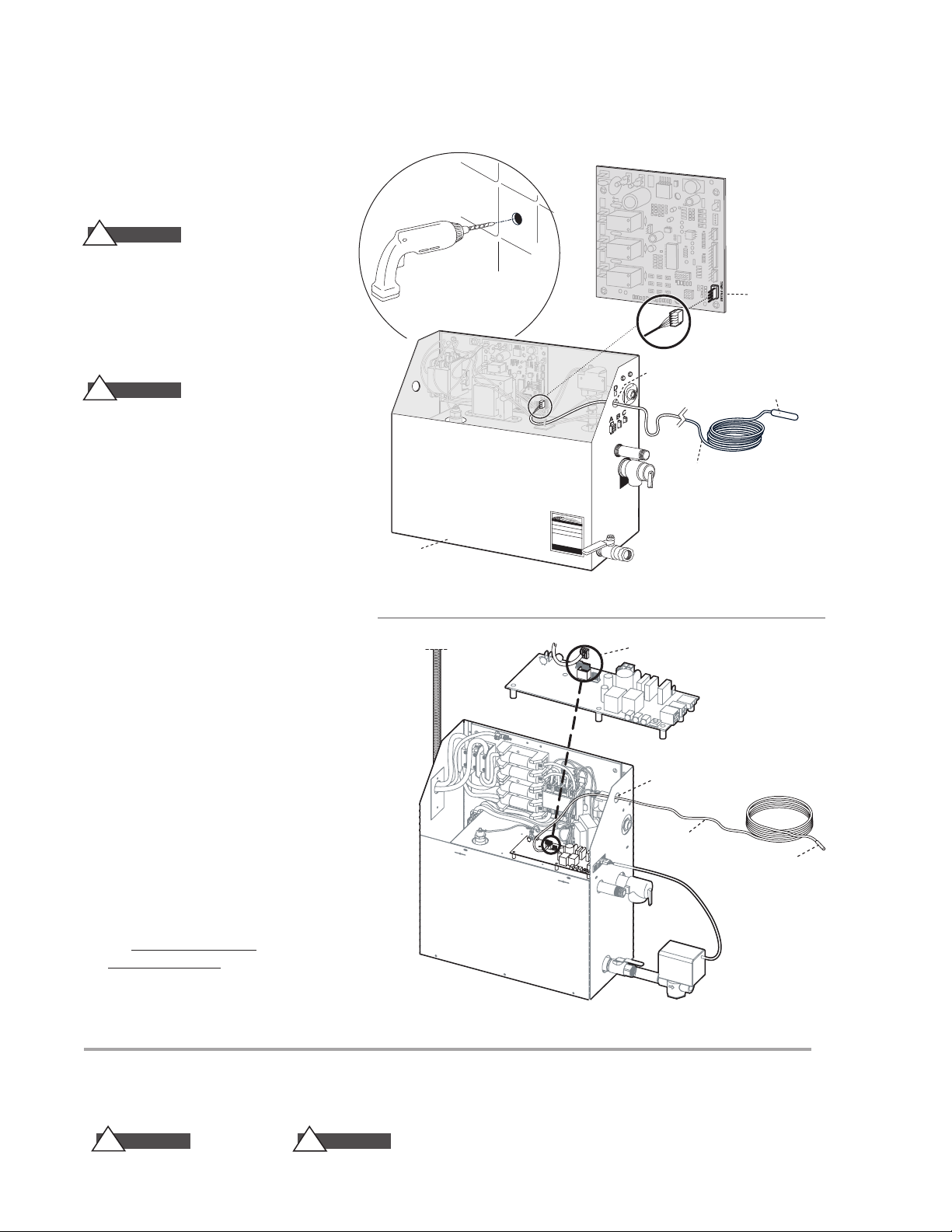
Installation Instructions for Remote Temperature Probe for
Mr.Steam
Steam Generator
(shown with cover removed
and NOT installed)
Temperature
Probe Cable
(30 feet)
Temperature
Probe Connection
Knock-Out
Temperature
Sensor Probe
M
r
.St
e
a
m
M
a
d
e
i
n
U
S
A
M
o
d
e
l
:
k
W
Vo
l
t
s
P
h
a
s
e
A
m
p
s
H
z
P
rinted Circuit Board
C
omponent shown for
illustrative purpose
MrSteam
Steam Generator
(shown with cover removed and NOT installed)
Knock-Out
Temperature
Sensing Probe
Temperature
Probe Cable
(30 feet)
Temperature Probe
Connection
Tempo®, Tempo/Plus®, eTempo®and eTempo/Plus®Controls
PN:MSTS
The Remote Temperature Probe is required
when the Tempo®, Tempo/Plus®, eTempo®and
eTempo/Plus®Controls are installed outside
the steam room.
CA U T I O N
!
(PN MSTS) is for use with Tempo
eTempo®and eTempo/Plus
use any other controls. Do not use any other
temperature probe with the
eTempo®and eTempo/Plus
products may result in an inoperative control and a
hazardous condition.
The Remote Temperature Probe
®
, Tempo/Plus®,
®
Controls only. Do not
Tempo®, Tempo/Plus®,
®
controls. Noncompatible
Diagram 1
CA U T I O N
!
Install the Tempo
eTempo®and eTempo/Plus
®
®
, Tempo/Plus®,
Controls according to
the installation and operation instructions supplied
with the Controls. Failure to do so may result in an
inoperative control and a hazardous condition.
1. Determine the location of the Remote
Temperature Probe:
The Remote Temperature Probe must be installed:
a. On a vertical surface
b. 4-5 feet above the floor
c. Locate the MSTS Temperature Sensor in a location representative of the desired steambathing
temperatures. Do not locate the MSTS above or
near the steam head or direct steam emissions.
The probe has an integral 30' cable. Insure that
the probe and/or steam generator are located
accordingly. Contact a MrSteam technical service
representative if a longer cable is required.
2. Drill a 5/16 inch diameter hole in the wall as
shown in Diagram 1. Do not oversize or undersize
the hole. Clean area thoroughly.
3. Remove the knock-out from the steam generator
jacket as shown in Diagrams 2 and 3.
4. Insert the remote temperature probe cable
through the knock-out and connect to the connector onthe steam generator printed circuit
board marked "TEMP PROBE"as shown in
Diagrams 2 and 3.
Diagram 2
steambaths
®
steam
.
mr
NOTE: FOR ILLUSTRATIVE
PURPOSES ONLY.
Consult with qualified designer, architect or
contractor for steam room construction details.
IMPORTANT NOTE:
As you follow these instructions, you will notice warning and caution symbols.This blocked information is important for the safe and efficient installation and operation of this generator.
These are types of potential hazards that may occur during this installation and operation:
WARNING
!
states a hazard may cause serious injury
or death if precautions are not followed.
!
signals a situation where minor injury or product
damage may occur if you do not follow instructions.
CA U T I O N
Diagram 3 (E Version)
DRAWINGS NOT TO SCALE
IMPORTANT NOTE:
This highlights information that is especially
relevant to a problem-free installation.
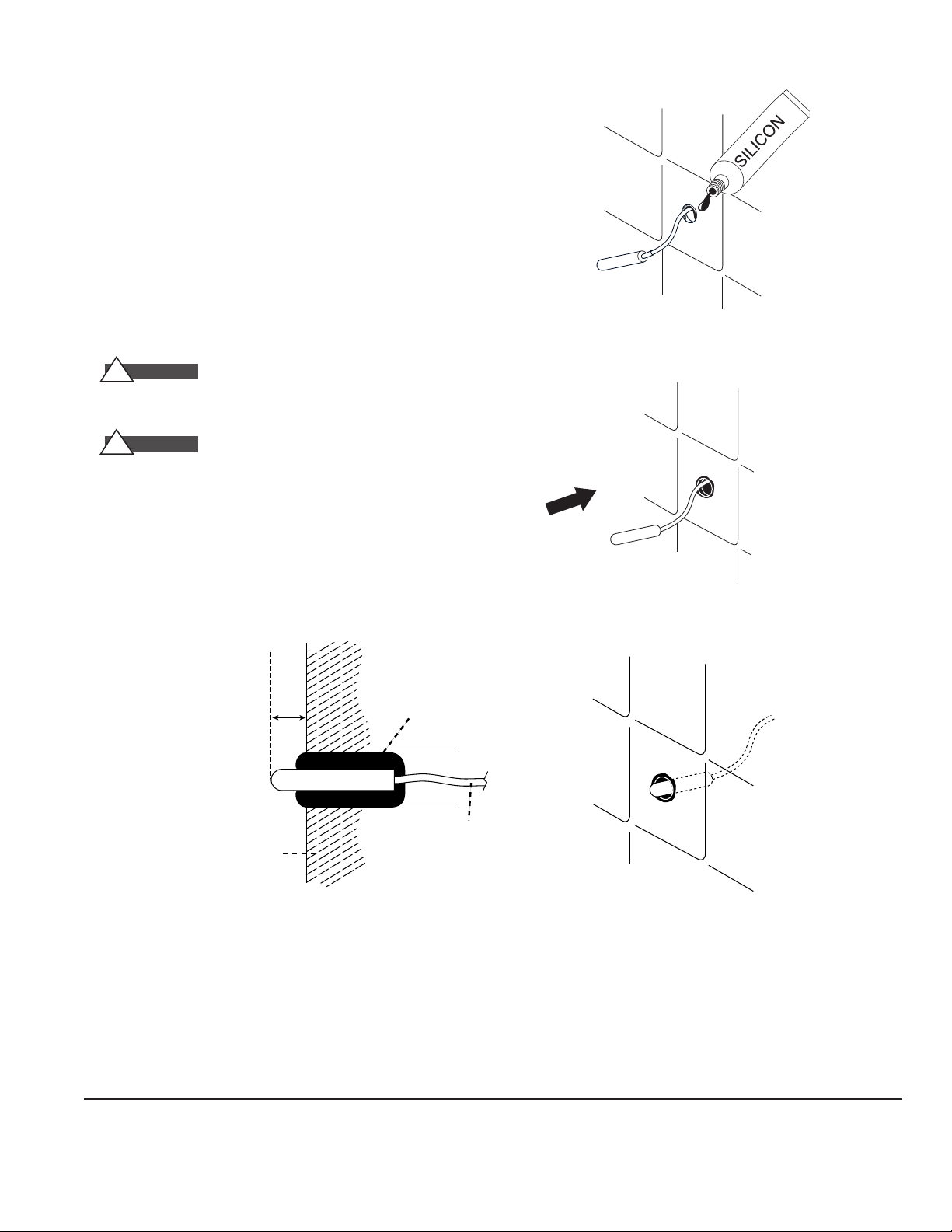
5. Route the end of the temperature probe cable with the temperature
INSTALLED REMOTE
TEMPERATURE PROBE
1
⁄4" Minimum
1
⁄2"
Maximum
Silicone Sealant
Cable
Wall
SECTIONAL VIEW
probe through the wall into the steam room as shown in Diagram 4.
IMPORTANT NOTE:
Do not strain, staple, pinch or otherwise damage
the probe cable.
6. With a minimal length of the cable exposed apply silicone (provided)
to the hole in the wall as required to create a moisture seal as shown
in Diagram 4.
7. Push the temperature cable and bulb into hole as required to leave
minimum 1/4", maximum 1/2" of the bulb exposed as shown below.
WARNING
!
Insure a minimum of 1/4" of the temperature bulb is
exposed to the air. Failure to do so may result in an inoperative control
and a hazardous condition.
CA U T I O N
!
The exposed area of the temperature bulb must be
free of silicone or any materials that prevent direct exposure to the steam
room air. Failure to do so may interfere with the ability to sense temperature and may result in excessive steam room temperatures.
Steam Room Interior
Diagram 4
Diagram 5
All information in these instructions is based on the latest product information available at the time of publication.
Sussman-Automatic Corporation reserves the right to make changes at any time without notice.
mr.steam
Sussman-Automatic
Corporation®
info@mrsteam.com
www.mrsteam.com
®
43-20 34th Street
Long Island City, NY 11101
Tel: 718-937-4500
Fax: 718-472-3256
9410 S. La Cienega Blvd.
Inglewood CA 90301
310-210-6565
Fax: 310-216-2944
PUR 100386 Rev. 11/08
 Loading...