

Page 1
®
mr.steam
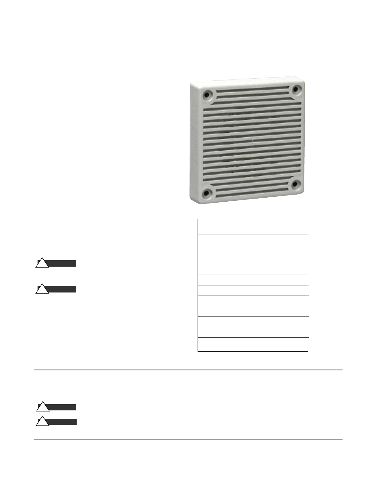
CU ALARM
___________________________________________________________________________________
The CU Alarm is an audible alarm
that sounds in the event the
steam room maximum set
temperature is exceeded or if the
CU-SteamStop button has been
pressed.
The CU Alarm may be mounted
outside the steam room in a
location that will alert an
attendant and/or user to an
over-temperature condition.
Review local codes for mounting location
as required
!
mounted inside the steam room.
.
WAR N IN G
The CU Alarm shall not be
d B A R AT I N G S
Tone High Standard
Horn 88 82
Bell 82 75
WAR N IN G
!
Instructions Carefully Before Using this
Product. The 115VAC CU Alarm must be field
set to the desired dBa sound output level and
alarm tone before installation. This is done
by adjusting a four position switch in accordance with these instructions. Incorrect settings will result in improper performance.
IMPORTANT NOTE:
This information is important for the safe and efficient installation and operation of this generator.
These are types of potential hazards that may occur during this installation and operation:
Please Read These
March Time Horn 85 79
*Code-3 Horn 85 75
*Code-3 Tone 79 75
Slow Whoop 88 82
Siren 85 82
Hi/Lo 82 79
*See note on Page 3
As you follow these instructions, you will notice warning and caution symbols.
dBA Reverberant
at 10 feet
CA U TI ON
!
WAR N IN G
!
mr.steam
Sussman-Automatic Corp.
info@mrsteam.com
www.mrsteam.com
states a hazard may cause serious injury or death if precautions are not followed.
signals a situation where minor injury or product damage may occur if you do not follow instructions.
®
®
43-20 34th Street
Long Island City, NY 11101
TEL: 718-937-4500 FAX: 718-472-3256
PUR 100452 Rev 4/10
9410 S. La Cienega Blvd.
Inglewood CA 90301
TEL: 310-216-6565 FAX: 310-216-2944
Page 2

mr.steam
SW 1
+
AUD -
Slide Here for (0)
Slide Here for (1)
O
N
1 2 3 4
SW1
O
N
1 2 3 4
_____________________________________________________________________________________________________________________________
®
CU ALARM
WAR N IN G
!
MAKE SURE THAT ALL FUSES USED ON SIGNALING
CIRCUITS ARE RATED TO HANDLE THE MAXIMUM INRUSH OR PEAK
CURRENT FROM ALL APPLIANCES ON THOSE CIRCUITS. FAILURE TO DO
THIS MAY RESULT IN LOSS OF POWER TO THE SIGNALING CIRCUIT AND
THE FAILURE OF ALL APPLIANCES ON THAT CIRCUIT TO OPERATE.
The CU Alarm produce a brief inrush current that lasts for just 50
microseconds at a peak value of 5.0 Amps.
WAR N IN G
!
IF 115VAC CU ALARMS ARE OPERATED WITHIN 15
INCHES OF A PERSON, THEY CAN PRODUCE A SOUND PRESSURE LEVEL
THAT EXCEEDS THE MAXIMUM 120 dBA PERMITTED BY ADA AND OSHA
RULES. EXPOSURE TO SUCH SOUND LEVELS CAN RESULT IN HEARING
DAMAGE.
SETTINGS:
The Switch (SW1) of the CU Alarm, shown in Figure 1, is used to set
the desired dBA sound output level and alarm tone. The factory settings are shown below. Read these instructions carefully before changing any of these factory settings.
Figure 1: PC Board Layout Showing Location of Switch
(Labeled SW1 on circuit board as shown)
THE FACTORY SETTINGS ARE:
HIGH dBA SW1 POS 1 set on 1
HORN TONE SW1 POS 2, 3, 4 set on 1, 1, 1
2
Page 3

mr.steam
P
O
S
1
P
O
S
2
P
O
S
3
P
O
S
4
USE A SMALL SCREWDR IVER TO
CHANGE THE SWITCH P OSITION.
Slide Here for (0)
Slide Here for (1)
_____________________________________________________________________________________________________________________________
®
CU ALARM
STEP 1:
Set desired dBA sound output by setting POS 1
of the four position switch (SW1). (refer to
Figure 2 and Table 2).
Figure 2: SW1 Switch
STEP 2:
Set desired alarm tone by setting the four-position switch (SW1). Use POS 2, 3, 4 to select
the desired alarm tone (refer to Table 3
below).
TA B L E 2
dBA Sound Output Level Settings
Decibel Level (dBA) POS 1
High dBA 1 (Factory Setting)
Standard dBA 0
TA B L E 3 Alarm Tones
SWI Switch Settings
___________________________________
Tone Pattern Description POS 2 POS 3 POS 4
Horn Broadband Horn (Continuous) (Factory Setting) 111
Bell 1560 Hz Modulated (0.07 Sec. ON/Repeat) 101
March Time Horn Horn (0.25 Sec.ON/0.25 Sec. OFF/Repeat) 001
* Code-3 Horn Horn (ANSI S3.41 Temporal Pattern) 1 1 0
* Code-3 Tone 500 Hz (ANSI S3.41 Temporal Pattern) 0 1 1
Slow Whoop 500-1200 Hz Sweep (4.0 Sec. ON/0.5 Sec. OFF/Repeat) 0 10
Siren 600-1200 Hz Sweep (1.0 Sec. ON/Repeat) 1 0 0
HI/LO 1000/800 Hz (0.25 Sec. ON/Alternate) 0 0 0
* NOTE: The Code-3 Horn and Code-3 Tone (set on HIGH dBA) incorporate the temporal pattern specified by ANSI/NFPA for standard emergency evacuation signaling. They should be
used only for fire evacuation signaling and not for any other purpose.
3
Page 4

mr.steam
REMOVE JUMPER FOR
OPTIONAL TIMER
STEAM SOLENOID
VALVE
Factory Wiring
Field Wiring
CU ALARM
N
L
DI G ITAL 1 CO N TROL
_____________________________________________________________________________________________________________________________
®
CU ALARM
WIRING THE ALARM TO A MR.STEAM CU COMMERCIAL STEAM GENERATOR:
WAR N IN G
!
SHOCK CAN CAUSE DEATH OR SERIOUS INJURY.
IMPORTANT NOTE: All electrical wiring is to be installed by a qualified, licensed electrician in
accordance with National and local electrical codes.
1. Strip leads 3/8 inches and connect to screw terminals. 115VAC CU Alarms have in-out wiring terminals
that accepts two #
Diagram: CU 360-4500 with 120 Volt Digital 1 Control:
SHUT OFF ALL POWER AT BREAKER BEFORE STARTING THE INSTALLATION. ELECTRIC
12 to #18 American Wire Gauge (AWG) wires at each screw terminal.
NOTES:
1. This Diagram shall only be used for wiring
CU-Alarms. Consult the CU Installation Manual
PUR 100376) for complete boiler wiring information.
(
2. The Over Temperature Portion (Change Wires) of
the D1 Temperature Controller must be connected
for the CU-Alarm to operate correctly.
4
Page 5

mr.steam
CU ALARM
CU ALARM
REMOVE JUMPER
FOR CU-HL
Control Terminal Block
Control Supply
120 Volt 1 PH 60 Hz
L
N
L
N
Factory Wiring
Field Wiring
_____________________________________________________________________________________________________________________________
®
CU ALARM
Diagram: CU 360-4500 with 120 Volt F1 Plus Control:
NOTES:
1. This Diagram shall only be used for wiring
CU-Alarms. Consult the CU Installation Manual
(PUR 100376) for complete boiler wiring information.
2. A CU-HL must be used in conjunction with each
CU ALARM on boilers with F1 controls.
5
Page 6

mr.steam
(2) #10-32 SELFTAPPING SCREWS
SIGNAL
(2) #8-32 SCREWS
4" SQ. X 2-1/8" Deep
ELECTRICAL BOX
_____________________________________________________________________________________________________________________________
®
CU ALARM
SURFACE MOUNTING:
IMPORTANT NOTE:
All electrical wiring is to be
installed by a qualified, licensed electrician in
accordance with National and local electrical codes.
Review local codes for mounting location as required
WARNING
!
DO NOT mount the CU ALARM
.
inside the steam room.
CAUTION
!
conduit fittings are used, check that installed CU Alarm has sufficient clearance and wiring room prior to installing electrical
boxes and conduit.
1.115 VAC CU ALARMs can be surface mounted to a
standard 4 inch square by 2-
box (Figure A)
2. Select the largest electrical box possible (shown in Mounting
Options) to provide the maximum wiring clearance for easy
installation.
3. Conduit entrance to electrical boxes should be selected to
insure sufficient wiring clearance for the CU Alarm. When
extension rings are required, conduit should enter through
electrical box, not extension ring.
4. Use care and proper techniques to position the field wires in
the electrical box so that they use minimum space and produce minimum stress on the product. This is especially important for stiff, heavy gauge wires with thick insulation or
sheathing.
5. Do not pass additional wires (used for other than signaling
appliances) through the electrical box. Such additional wires
could result in insufficient wiring space for the signaling
appliance. The CU Alarm is designed to produce an audible
alarm in the event the steam room maximum set temperature
is exceeded.
6. Place the CU-ALARM identification label on or adjacent
to the alarm.
IMPORTANT NOTE:
incorporate the temporal pattern specified by NSI/NFPA/
ISO for standard emergency evacuation signaling.
They should be used only for fire evacuation signaling
and not for any other purpose.
If sheathed multiconductor cable or 3/4"
1
/8inch deep electrical
STEAMROOM ALARM
mr.steam
43-20 34th Street, Long Island City, NY 11101 1 800 76 STEAM
The Code-3 Horn and Code-3 Tone
®
www.mrsteam.com
OPERATIONAL CHECK:
WHEN USED WITH THE DIGITAL 1 CONTROL:
1. Disconnect the probe wire connection at the back of the
Digital 1 Control.
2. The boiler will shut off and the alarm will sound
(the Digital 1 will read o o o).
3. If the alarm does not sound, disconnect power and swap the
orange wires at terminal 7 & 8 on the back of the control.
4. Reconnect power and follow the operational check
instructions.
WHEN USING THE CU-STEAMSTOP:
1. Press the CU-STEAMSTOP (the Digital 1 will read - - -)
2. The boiler will shut off and the alarm will sound.
3. If the alarm does not sound, disconnect power and swap
the orange wires at terminal 7 & 8 on the back of the control.
If the Digital 1 control does not display - - -, refer to the
CU-STEAMSTOP Installation operation & Maintenance Manual.
4. Reconnect power and follow the operational check
instructions.
WHEN USED WITH THE F1 PLUS CONTROL AND CU-HL:
1. Turn the CU-HL temperature dial down until the
boiler turns off.
2. The alarm will sound. Reset the CU-HL set point.
3. If the alarm does not sound disconnect power and
check wiring.
6
 Loading...