

Page 1
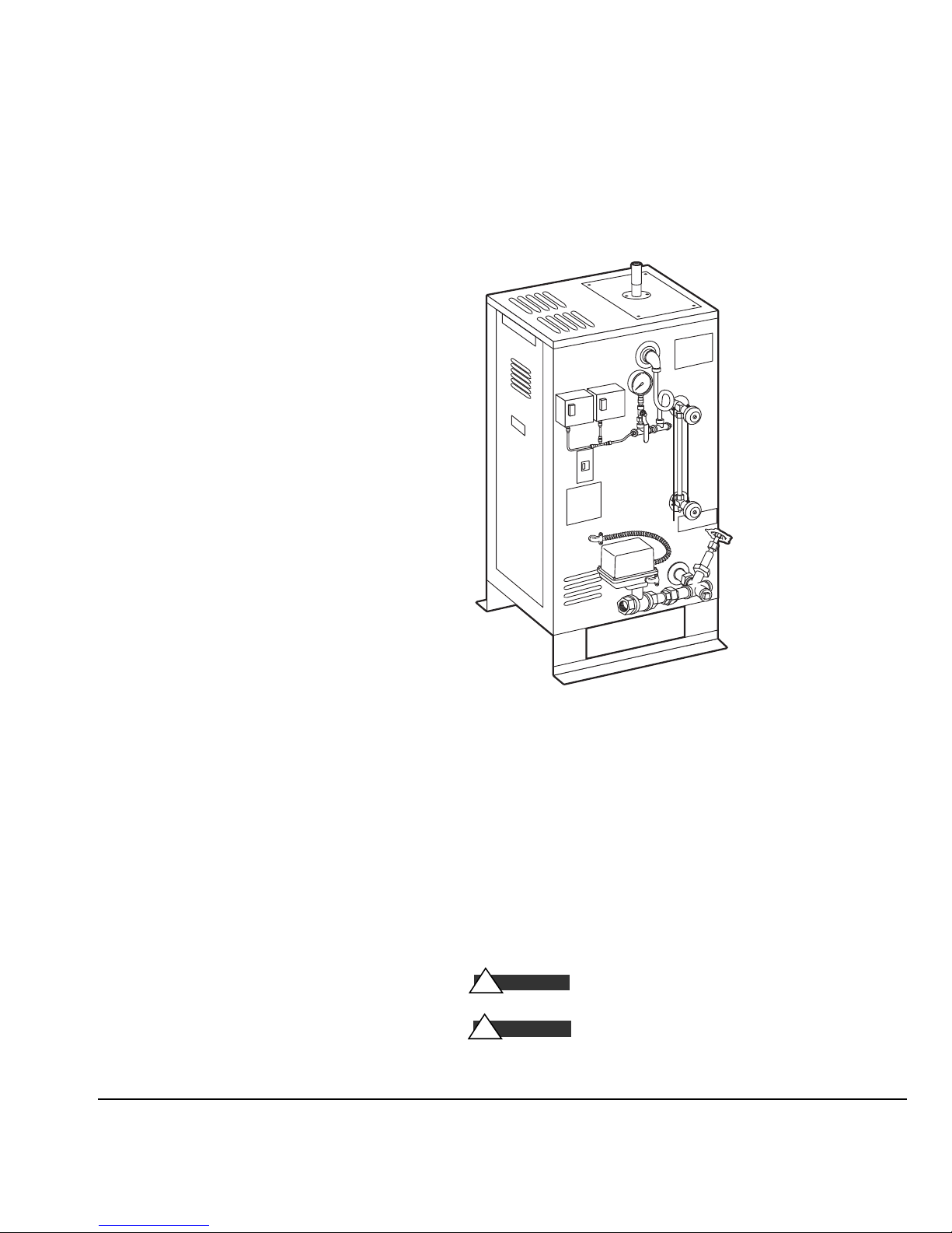
CU Series Steambath Generators
Installation, Operation & Maintenance Manual
Models: CU-360 through CU-4500
_________________________________________
IMPORTANT: LEAVE THIS MANUAL WITH THE OWNER/OPERATOR
_________________________________________
Table of Contents
Before Installing . . . . . . . . . . . . . . . . . . . . . . . .2
Steam Room Guidelines . . . . . . . . . . . . . . . . . .2
Locating the Steambath Generator . . . . . . . . . . . .3
Dimensional & Clearance Specifications . . . . . . .4
Selecting the Steambath Generator . . . . . . . . . . .5
Installation: Plumbing, Water Supply, Steam Line,
Drain, Safety Valve . . . . . . . . . . . . . . . . . . . .6
Water Quality Information . . . . . . . . . . . . . . . . . .6
Steam Room Guidelines . . . . . . . . . . . . . . . . . . .7
Steam Head & Acrylic Shield . . . . . . . . . . . . . . .7
Electric . . . . . . . . . . . . . . . . . . . . . . . . . . . . . .8
Wiring . . . . . . . . . . . . . . . . . . . . . . . . . . . . . .9
Control Circuit Wiring Diagrams . . . . . . . . .10-13
Digital 1 Control: Contents . . . . . . . . . . . . . . . .14
Control Installation . . . . . . . . . . . . . . . . . . .15
Temperature Sensor Installation . . . . . . . . . . .16
Automatic Blowdown System
Contents . . . . . . . . . . . . . . . . . . . . . . . . . .16
Installation . . . . . . . . . . . . . . . . . . . . . . . . .17
Auxiliary Manual Reset Low Water Cutoff . . . . . .18
Principles of Operation . . . . . . . . . . . . . . . . . . .19
Operating and Testing
Automatic Blowdown, Digi tal 1 Control , CU-HL
Warning Signage . . . . . . . . . . . . . . . . . . . . . .21
Pre-Operation Check . . . . . . . . . . . . . . . . . . . . 21
Operation:
Automatic Blowdown Instructions . . . . . . . . .22
Manual Blowdown Instructions . . . . . . . . . . . .22
Maintenance Instructions . . . . . . . . . . . . . . . . . . 23
Water Gauge & Gauge Glass: Installation . . . . . . .24
Water Gauge & Gauge Glass: Use and Care . . . . .25
24-hour and 7-day Time Switches . . . . . . . . . . . .25
Trouble Shooting . . . . . . . . . . . . . . . . . . . . . . .26
Check:
PC Boards, Probes, Steam Solenoid Valve,
Digital 1 Control, Heating Element . . . . . . . . .27
Element Replacement Instructions . . . . . . . . . . . 28
Typical Component Arrangement
CU 360–CU 1400 . . . . . . . . . . . . . . . . . . . .29
CU 2000–CU4500 . . . . . . . . . . . . . . . . . . .30
Replacement Parts List . . . . . . . . . . . . . . . .31-32
. .20
Typical CU Series Steambath Generat or
(for ill ustrative p urpos es only)
IMPORTANT NOTE:
you will notice warning and caution symbols. This information is important for the safe and efficient installation
and operation of this generator. These are types of potential hazards that may occur during this installation and
operation:
CA U T I ON
!
death if precauti ons are not fo ll owed.
WARN I N G
!
product damage may occur if y ou do not fol lo w instructio ns.
As you follow these instructions,
states a hazard may cause s erious injury or
sign als a situatio n where minor i njury or
®
steambaths
®
steam
.
mr
mr.steam
Sussman-Automatic Corp
[email protected]
www.mrsteam.com
®
43-20 34th Street
®
Long Island City, NY 11101
TEL: 800 76 STEAM
FAX: 718 472 3256
9410 S. La Cienega Blvd.
Inglewood CA 90301
TEL: 800 72 STEAM
FAX: 310 216 2944
1
PUR 100376 11/10
Page 2

mr.steam
Before Installing
®
CU Series Installation, Operating & Maintenance Manual
IMPORTANT:
Although this CU Steambath Generator has been qualified for shipment by Mr. Steam, the
following must be reviewed for proper and safe use.
1.
Verify that the model and accessories are as specified and
ordered.
2.
Verify that the power voltage and control voltage at the site
is suitable for the CU Steambath Generator.
3.
Verify the correct steam generator sizing by referring to the
Mr.. Steam sizing guide. See page 5.
4.
Do NOT use black iron pipe or galvanized pipe for the
steam line. Use brass pipe or copper tubing ONLY, and
in accordance with National and local plumbing Codes.
5.
The physical size of the unit, clearance for plumbing
servicing and its distance from the steam room must all
be considered before selecting a location for the generator.
See pages 3 & 4.
Take time to read these instructions thoroughly before installing or servicing.
6.
The Manufacturer's Data Report is supplied with the generator. This is an important document and may be required by
a State or Provincial Agency. THIS DOCUMENT MUST
BE SECURED IN A SAFE LOCATION.
7.
Do not use or install unauthorized components, accessories
or products on the generator or generator piping.
IMPORTANT:
over temperature control is to be installed in accordance with
the specific instructions provided. See Note 7 below.
The Mr. Steam Digital 1 System operating and
Steam Room Guidelines
IMPORTANT:
used in conjunction with your architect, designer and contractor
in determining all factors necessary in providing a suitable and
safe steam room environment for your bathers.
IMPORTANT:
familiarize themselves with the latest edition of the American
College Sports Medicine Health/Fitness Faculty Standards and
Guidelines, or a similar resource and reference publication, and
refer to those guidelines for the proper and safe operation of a
spa facility including steam rooms.
Steam room construction information is available from the
Tile Council of America, Inc. at (864) 646-8453 or
www.tileusa.com
1.
Steam room must be completely enclosed, with full walls,
door, floor and ceiling.
2.
It is recommended that a gasketed door be used for heat sealing and steam containment. Windows, skylights and the like
that are part of the steam room should be double paned.
Only vapor sealed lighting fixtures approved for the application should be used.
CA U T I ON
!
the flooring, provide suitable anti-skid strips or equivalent,
to prevent user slipping and injury.
The following general information should be
Owners/operators should obtain a copy and
3.
If tile or other smooth surface is used for
IMPORTANT:
4.
Walls and ceilings must be constructed with water-resistant,
non-corrosive surface, such as tile, marble, molded acrylic,
or other non-porous material. The ceiling should be sloped
to prevent dripping of condensate on bathers. If acrylic,
fiberglass or other non-heat resistant- materials are used as
part of the steam room enclosure, see page 7, “Steamhead ”
and “Acrylic Shield” for important additional details.
5.
Provide floor drains for condensate run-off and steam room
cleaning.
6.
Comply with all applicable National and local building
and electrical Codes and confer with design consultants and
contractors for room construction details.
CA U T I ON
!
System is required operating equipment for each steam
room. The operating temperature control is to be set by the
owner/operator to sense desired room temperature at the
sensor location within the steam room. Connection of the
Digital 1 Over Temperature cut-off is mandatory to
provide additional protection to the bathers. The steam room
is to be operated in accordance with “Important” ºinformation as noted above.
IMPORTANT:
setting is at the discretion of the owner/operator.
7.
The Digital 1 Temperature Control
Final selection of the steam room temperature
2
Page 3
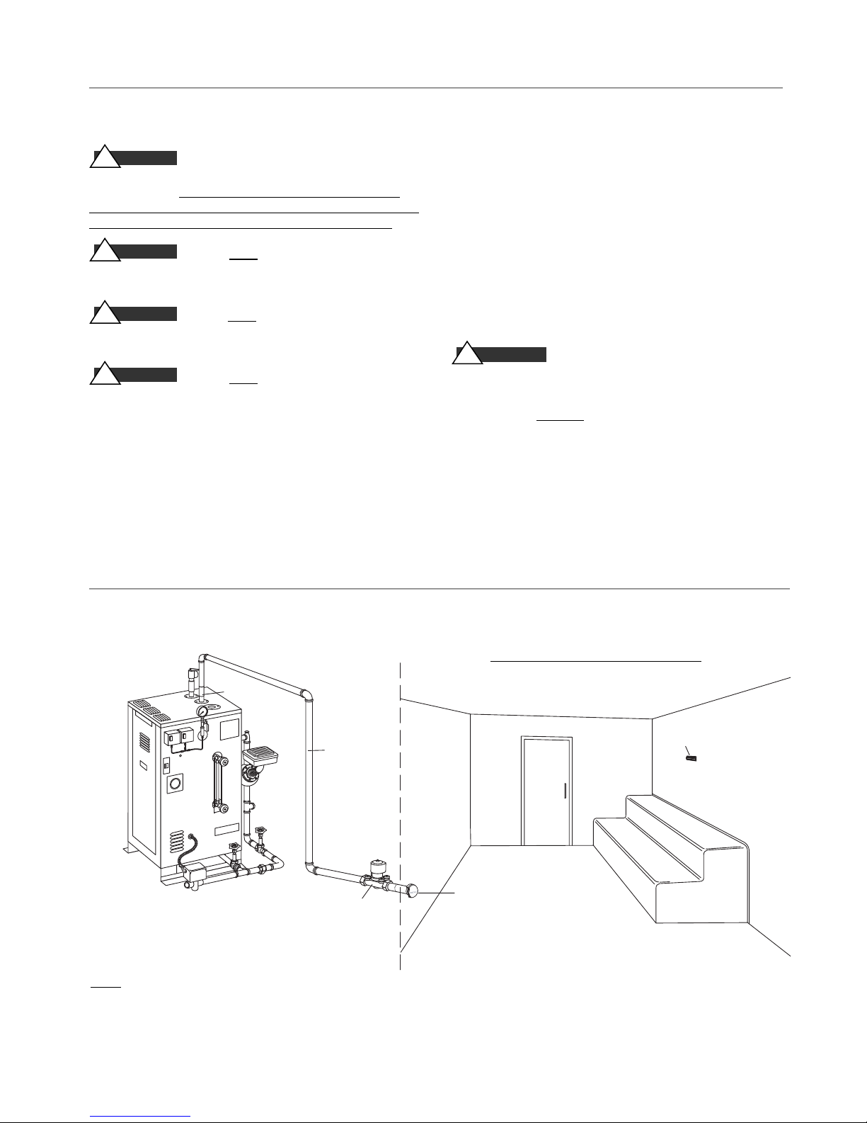
mr.steam
U T I L I T Y R O O M
Figure 1
3
⁄4" Steam
Solenoid
3
⁄4" Steamhead
with Acrylic Shield
Steam
Generator
Fully
Insulated
Steam Pipe
Digital 1 Sensor
1" Steam
Outlet
S T E A M R O O M
e
®
CU Series Installation, Operating & Maintenance Manual
Locating the Steam Generator Unit
CA U T I ON
!
generators are designed to NEMA Type 1 requirements and
are intended for indoor use only. They are to be located
indoors in a dry, clean location and are not to be subjected
to moisture, condensate, hose wash down or the like.
CA U T I ON
!
outdoors or wherever environmental conditions may effect
the safety and/or performance of the generator.
CA U T I ON
!
locations such as unheated attics or basements, or where
water could freeze.
CA U T I ON
!
near flammable or corrosive materials, or chemicals such as
gasoline, paint thinners, or the like. Installation in areas
having high concentrations of chlorine (such as pool equipment room) must be avoided.
5. IMPORTANT: Select a location for steam generator in
accordance with items 1-4 above and within 25 feet of
the steam room. Reference “Dimensional & Clearance
Specifications” information on page 4. See page 5 for
guidance if generator is more than 25 feet from steam
room.
1. Mr.Steam®CU commercial steambath
2. Do NOT install steambath generator
3. Do NOT
4. Do NOT
install steambath generator in
install steambath generator
. Install steambath generator on a solid and level surface,
6
and mechanically secure generator in place.
7. Provide access to the steambath generator for servicing.
See page 4 for Dimensional & Clearance Specifications
8. IMPORTANT: Steam line, safety valve and drain valve and
plumbing, and steamheads become hot during operation
and remain hot after shutdown for a period of time.
Provide appropriate protection, including insulating
plumbing lines. Avoid plumbing runs and steam head
locations that can come in contact with service personnel
and bathers. See page 6.
WARN I N G
!
from the bather seating areas and traffic patterns.
IMPORTANT: A LOCKED UTILITY ROOM THAT ONLY PERMITS
ACCESS TO THE STEAM GENERATOR AND ITS CONTROLS BY
AUTHORIZED PERSONNEL AND IS NOT ACCESSIBLE TO THE
GENERAL PUBLIC IS STRONGLY RECOMMENDED.
9. Each steamhead must be located away
Mr. Steam Installation
NOTE: FOR ILLUSTRATIVE PURPOSES ONLY. Optional equipment shown.Consult with qualified designer, architect
or contractor for steam room construction details, including location of steam head(s) and sensors.
3
For Illustrative Purposes Only
Page 4
mr.steam
®
CU Series Installation, Operating & Maintenance Manual
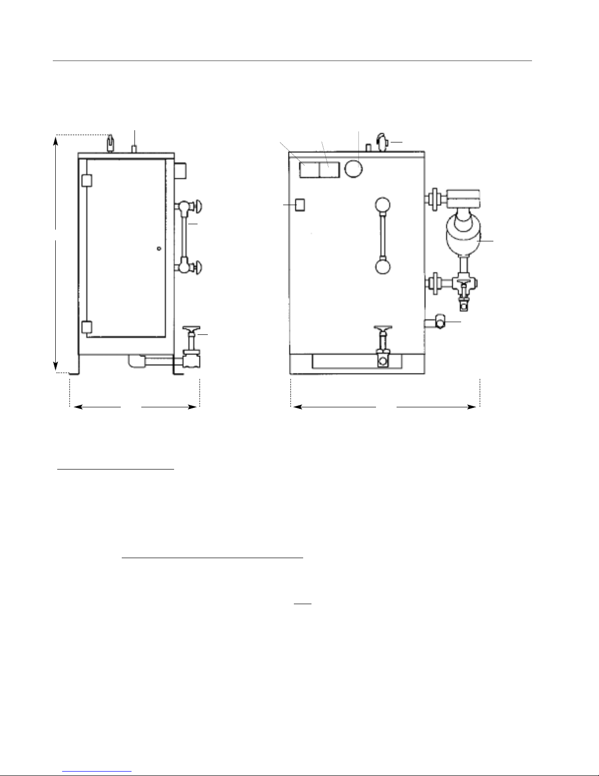
Dimensions & Clearance Specifications
Height
Steam Outlet
Operating
Pressure
A
Gauge Glass
Assembly
Control
On/Off
Switch
High Limit
Pressure
Control
D
E
L
Pressure
Gauge
15 PSIG
Safety Valve
MM 150 Liquid
Level Control
E
R
(see note 2)
B
Water Feed Inlet
Drain Valve
FrontLeft
Width Length
F
Figure 2:
Typical Arrangement of Boiler with McDonnell Miller.
For illustration purposes only.
Refer to all notes below
NOTES for Figure 2:
1.
All dimensions are approximate. Refer to chart on Page 5.
2
. MM150 Liquid Level Control on CU-2000 and larger models only.
CU-360 to CU-1400 have electronic liquid level controls.
3. IMPORTANT
: Minimum clearance from combustible surfaces.
Refer to Fig. 2 above for legend.
A
1" above top of CU generator
B
Front of CU generator suitable for alcove installation only.
D
1" from rear of CU generator.
E
1" from left side of CU generator.
L
E
16" from right side of CU generator.
R
F
Type of flooring: “C", suitable for combustible flooring.
4.
For ease of servicing, Mr. Steam recommends a minimum of
36 inches of clearance all around the CU generator.
4
Page 5

mr.steam
®
CU Series Installation, Operating & Maintenance Manual
Select a Mr. Steam®CU Series Generator
The resultant calculated volume of the steam room determines
the Model CU steambath generator required. Steam room size
and additional constructional factors affect model selected.
A.
To determine the steam room volume first multiply
Length x Width x Height of the steam room
__________________________________________________
Example: A steam room 8' x 9' x 8' = 576 Cu. Ft.(volume).
Select the Mr. Steam Model which is the next larger volume.
In this example, Model CU-750 is the correct selection.
Example: 2 Steam rooms each 6' x 10' x 7' x 2 rooms = 840
Cu. Ft. (volume).
In this example, Model CU-1000 is the correct selection.
SEE NOTE B BELOW
NOTE:
Insure adequate consideration is given to assure that the
CU unit selected is not undersized for the room.
B. NOTE:
the steambath generator:
1.
2
. Piping runs longer than 25 feet from the steambath genera-
3
. Exterior walls and outside windows: Increase volume.
Certain additional factors effect the correct sizing of
Construction materials such as glass or glass block, natural
marble or other stones: Increase volume.
tor to the steam room: Increase volume.
4
. Steam room with interior height in excess of 8 feet:
Increase volume
C. IMPORTANT:
recommendations only. Always
designer or architect. For general information, contact East
Coast: 1-800-767-8326 or West Coast: 1-800-727-8326.
D. IMPORTANT:
Steambath generator the following is strongly recommended for best performance and user satisfaction.
1
. One CU steambath generator should service no more that
two (2) steam rooms, each relatively similar in size and
construction.
2.
If two (2) steam rooms are serviced by one (1) CU generator, the combined resultant room volume of the two rooms
should not exceed 1000 cubic feet.
3.
Each room must be operated with the appropriate Digital 1
temperature control system inclusive of the room operating
temperature control and the high-limit temperature control.
4.
In any case, the purchase and/or owner/operator must consult with a designer, architect, and/or consultant to assure
the proper specification of the steam generator.
The above selection guidelines are
consult with contractor,
When specifying a CU Commercial
Model No. KW Room Volume (cu ft) Size NPT Outlet Size, NPT Width Length Height Wt. lbs.
CU-360 9 400 3/8" 1" 20 30 38 250
_____________________________________________________________________________________________________
CU-500 12 500 3/8" 1" 20 30 38 250
_____________________________________________________________________________________________________
CU-750 18 750 3/8" 1" 20 30 38 250
_____________________________________________________________________________________________________
CU-1000 24 1000 3/8" 1" 20 30 38 270
_____________________________________________________________________________________________________
CU-1250 30 1250 3/8" 1" 20 30 38 290
_____________________________________________________________________________________________________
CU-1400 36 1400 3/8" 1" 20 30 38 300
_____________________________________________________________________________________________________
CU-2000 48 2000 1/2" 1" 24 33 44 330
_____________________________________________________________________________________________________
CU-2500 60 2500 1/2" 1" 24 33 44 380
_____________________________________________________________________________________________________
CU-3000 72 3000 1/2" 1" 24 33 44 390
_____________________________________________________________________________________________________
CU-4500 108 4500 1/2" 1-1/2" 28 34 59 625
_____________________________________________________________________________________________________
*After taking into consideration all factors affecting resultant steam room volume, including materials of construction, distance
from generator to steam room, interior height of steam room ceiling, outside/exterior walls and windows etc, select proper
Model CU generator. Consult with an architect, engineer, designer and/or contractor before making final selection
Maximum* Water Inlet Steam Generator Dimensions (inches) Shipping
.
5
Page 6
mr.steam
Installation
®
CU Series Installation, Operating & Maintenance Manual
Plumbing
All plumbing shall be performed by a qualified
licensed plumber and in accordance with applicable
National and local Codes.
Water Supply
1.
Connect to hot or cold water line. A hot water line
is preferable, however incoming hot water should
not exceed 160°F
IMPORTANT:
hot water heaters provides 120°F water
2.
Provide a service shut off valve and water-line
strainer in the water supply line upstream to the
steambath generator
3.
Flush the inlet water line thoroughly before making connection to the steambath generator.
4.
Incoming water supply should be at least 25 psig
and is not to exceed 100 psig.
5.
Install a back flow preventor as required by Code.
6.
Provide anti-water hammer device as required in
accordance with Code.
7.
Use of unions in plumbing lines is strongly
recommended.
8.
Recheck all factory and field plumbing connections for tightness.
The low temperature setting on many
Steam Line
1.
The Digital 1 steam solenoid valve should be plumbed as close as
practical to the steam room using only brass pipe or copper tubing
but should remain accessible for service.
2.
Pitch the steam line a minimum of 1/4”per linear foot of run,
towards the steam outlet on the generator, avoid valleys and trapping of condensate.
3.
Fully insulate steam lines with suitably-rated high temperature
insulation.
4.
Install a suitable strainer or filter between the steam generator and
steam solenoid valve.
5.
Use of unions in plumbing lines is recommended.
Drain
In accordance with Code requirements, provide a drain line
connection from the steambath generator drain valve(s). If an Auto
Blowdown is used, the drain line must be connected to
the automatic blowdown valve. Refer to National and local plumbing
Codes for drain requirements including receptor,
trap, vent requirements and drain lines.
Safety Valve
Where permitted by Code, provide a
connection for safety |valve discharge.
P I P E SI Z E GU I D E
_____________________
Steam Outlet: 1"
Steam Solenoid Valve:3/4"
Steam Head: 3/4"
WARN I N G
!
DO NOT
DO NOT
connect a shut off valve or plug at the safety valve outlet.
reduce outlet size of safety valve discharge.
Water Quality Information
For optimum results, the feedwater supply should be
tested prior to initial startup. If the mineral content
exceeds the following recommended limits, various
external treatment processes may be used to correct the
problem.
NOTE:
An analysis of the on-site boiler feedwater must
be made by a recognized and reliable water treatment
company to ascertain the existing condition and treatment required.
Recommended Feedwater Quality
Hardness, ppm 8 – 85 (~0.5 – 5 gpg)
P-Alkalinity, ppm 85 – 410 (~5 – 24 gpg)
T. Alkalinity, ppm 200 – 500 (~7 – 0 gpg)
pH (strength of alkalinity) 8.0 – 11.4
Blowdown boiler at least a once a day. If boiler water
or feed-water are outside the above limits, a more
frequent blowdown is required
Recommended Limits Within a Boiler
Total Dissolved Solids, ppm 3500 Sulfite (SO3), ppm 25 – 50
Total Alkalinity, ppm 850 Phosphate, ppm 30 – 60
Suspended solids, ppm 300 P-Alkalinity as CaCO3, ppm 900
Silica (SiO2), ppm 125 Iron, ppm 2
Water quality can affect efficiency or result in boiler damage if neglected. Boiler feedwater contains impurities in solution and suspension.
These impurities concentrate in the boiler. The concentration of these
impurities increases as more feedwater is introduced into the boiler and
steam is produced. If the suspended solids are allowed to concentrate
beyond certain limits, a deposit or “scale” will form on the boiler
internal surfaces. This deposit can interfere with the proper boiler
operation and cause boiler failure.
The concentration of these impurities is generally controlled by the
feedwater quality and by blowdown. Blowdown refers to removing a
portion of the boiler water with high solids concentration and replacing it with makeup water of a lower concentration.
6
Page 7
mr.steam
Fully Assembled
Assembly
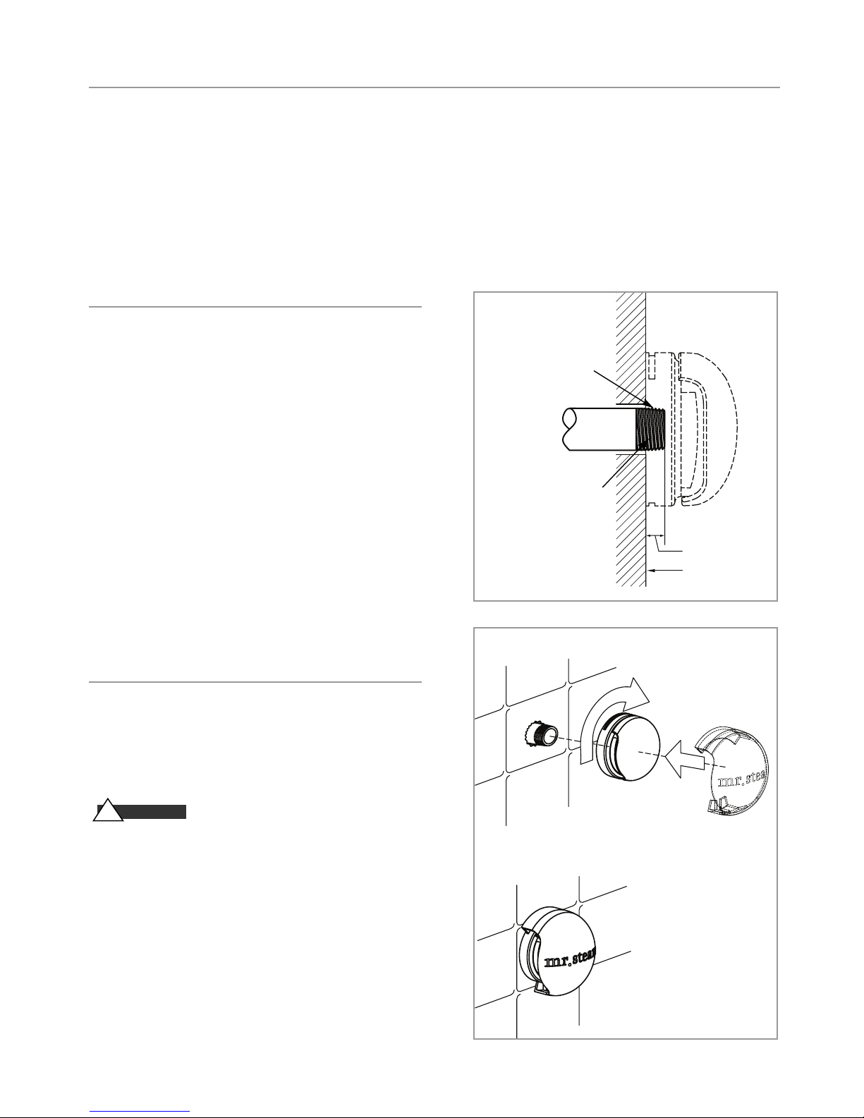
Steam Head
Steam Pipe
Acrylic Sheild
®
CU Series Installation, Operating & Maintenance Manual
Steam Room Guidelines
IMPORTANT:
and contractor in determining all factors necessary in providing a suitable and safe steam room environment
for your bathers.
IMPORTANT:
American College of Sports Medicine Health/Fitness Faculty Standards and Guidelines (ISBN: 0736051538),
or a similar resource and reference publication, and refer to those guidelines for the proper and safe operation
of a spa facility including steam rooms.
Steamhead
1
. For steam rooms constructed of tile, marble or similar non-
porous heat-resistant materials for the enclosure, locate
steam head 12 inches above steam room floor and install
Mr. Steam PN CU-103985 acrylic shield on each steamhead.
IMPORTANT:
other non-heat resistant materials used for steam room enclosure, install each steam head 20-30 inches above the floor.
2.
Locate each steamhead away from bather seating area and
away from traffic patterns.
3.
Install each steamhead with steam slots facing to the left
and right as shown in the diagrams.
4. NOTE:
or other tools to tighten. Use of proper thread sealant and
hand tightening is usually sufficient.
5.
Apply a bead of silicone around the steamhead where it
meets the wall.
The following general information should be used in conjunction with your architect, designer
Owners/operators should obtain a copy and familiarize themselves with the latest edition of the
(3/4” N.P.T.)
Use Teflon or equal
sealant on pi pe t hreads
Steam
For Steam rooms using acrylic, fiberglass or
To preserve the steamhead finish, do not use wrench
Fill g ap with sili cone or
equal sealan t as required
Diagram A
Supply P ipe
for mois ture seal
Steam Head
3/4”
Finis hed in terior face
of steam ro om wall
Acrylic Shield
Apply a small bead of silicone in the grooves on the top and
bottom of the steamhead. Place an Acrylic Shield (PN 103985)
over the steamhead until the tabs engage the grooves in the
steamhead.
WARN I N G
!
acrylic shield may expose users or surfaces to hot steam. Do
not operate steam room without an acrylic shield on each
steamhead.
IMPORTANT:
containing emulsifiers or aldehydes. Acrylic Shield damage may result.
Mr. Steam oils are approved for use with this acrylic shield.
Operation of the steam room without an
Do not use with water soluble fragrance or fragrance
Diagram B
7
Page 8

mr.steam
®
CU Series Installation, Operating & Maintenance Manual
Electric
WARN I N G
!
switch before proceeding. All electrical wiring must be installed by a qualified licensed electrician
in accordance with National and local Codes.
The steambath generator is factory wired and pre-tested before shipment. Electrical power supply
details are provided on the data plate secured to the generator and as part of this manual. Refer to
applicable wiring and schematic information.
1.
Check power and control circuit voltage requirements on the data plate.
NOTE:
Separate 120 VAC line is not required if optional 120 VAC control transformer has been
purchased and provided as factory equipment.
2.
Use minimum 90° C insulated copper conductors only for field wiring, sized in accordance
with National and local electric Codes. Refer to Amperage Chart below.
3.
Connect suitably sized copper equipment grounding conductor in accordance with National and
local electric Codes to ground terminal provided.
4.
Install a separate dedicated circuit breaker or other approved overcurrent protection device
between the incoming electrical supply and the generator, in accordance with National and local
electric Codes.
5. IMPORTANT:
tighten all electrical connections including all factory connections at the terminal block, fuse
block, top and bottom of contactor and element pins prior to energizing generator (torque
values are listed on individual components, control circuit terminal strips should be torqued
to 20 in-lbs.).
Electric shock hazard. Disconnect all power supplies at the main disconnect
With main disconnect switch off and no electric power entering the generator,
AMPERAGE CHART - Indicates Total Ampere Draw of Specific CU Model at Voltage & Phase Specifie
Model No. kW 208V/1 PH 208V/3 PH 240V/1 PH 240V/3 PH 480V/3 PH 600V/3
PH
________________________________________________________________________________________
CU-360 9 44 25 38 22 11 9
________________________________________________________________________________________
CU-500 12 58 34 50 29 15 12
________________________________________________________________________________________
CU-750 18 87 50 75 44 22 18
________________________________________________________________________________________
CU-1000 24 116 67 100 58 29 24
________________________________________________________________________________________
CU-1250 30 145 84 125 73 37 29
________________________________________________________________________________________
CU-1400 36 - 100 - 87 44 35
________________________________________________________________________________________
CU-2000 48 - 134 - 116 58 47
________________________________________________________________________________________
CU-2500 60 - 167 - 145 73 58
________________________________________________________________________________________
CU-3000 72 - 200 - 174 87 70
________________________________________________________________________________________
CU-4500 108 - 300 - 260 130 104
________________________________________________________________________________________
IMPORTANT: Use minimum 90° C insulated copper conductors only for field wiring sized in accordance with
National and local electric Codes.
NOTE:
Consult factory for other voltage/phase combinations. CU generators are suitable for 50/60 hz. Standard
control circuit voltage for above V/PH combinations for United States, Canada and Mexico is 120 VAC.
Exception: 220-240 VAC control circuit voltage is provided on non-domestic product where power voltage is 220240 V/3 PH, 380V/3PH, 415V/3 PH, etc.
d
8
Page 9

mr.steam
®
CU Series Installation, Operating & Maintenance Manual
Wiring
CA U T I ON
!
steambath generator shall be suitably grounded in accordance with National Electric and local Codes. Disconnect all
power supplies at the main disconnect switch before proceeding.
1.
Electric wiring to the steambath generator must be in
accordance with National Electrical and local wiring
Codes following wiring diagram supplied. Such wiring
shall be done by a licensed electrician. See Amperage
Chart and Notes, Page 8.
2.
The unit is wired and pre-tested before shipment. Follow
all instructions provided for safely and properly wiring
steambath generator and accessories.
CA U T I ON
!
quate capacity employing suitably rated circuit breakers or
fuses between main electrical power source(s) and the generator. Location of safety switch to be in accordance with
National and local electric codes.
To avoid possible electric shock, the
Installer shall use a safety switch of ade-
. IMPORTANT:Insure all electrical connections are sufficiently
3
tightened prior to energizing generator.
See Page 8, Item 5.
WARN I N G
!
of wiring systems voids warranty and can lead to dangerous
operating conditions.
4.
The Digital 1 Temperature Sensor and High Limit
Temperature sensor(s) must be located inside the steam room.
Locate approximately 5 feet above the steam room floor,
preferably away from steam heads.
5.
The Digital 1 steam solenoid valve(s) shall be located outside
the steam room and shall be wired to the Digital 1 controller(s) in accordance with wiring diagram provided. See
applicable wiring diagrams included as part of this manual.
CA U T I ON
!
securely crimped soldered and sealed with heat shrink tubing.
Substitution of components or modification
Ensure all splices in the sensor cable are
Typical Power Wiring Diagram
__ __ __ __
__________
IMPORTANT:
Field Wiring
Factory Wiring
3PH Power Supply
Diagram #1
Units with 1 Contactor (see note 1)
Also refer to Control Circuit diagrams in this manual.
GRD
Power Contactor
Heating Element
3PH Power Supply
GRD
Power Terminal Block
Power Contactors
Heating Elements
Diagram #2
Units with 2 or more Contactors (see note 1)
9
Page 10

mr.steam
®
CU Series Installation, Operating & Maintenance Manual
Control Circuit Wiring Diagram
SEE PAGES 11, 12 & 13 FOR DIAGRAMS
CA U T I ON
!
Installer shall use a safety switch of adequate capacity employing suitably rated circuit breakers or fuses between main electrical power
source(s) and the generator. Location of safety switch to be in accordance with National and local electrical codes.
NOTES:
1.
Larger rooms may require two or more steam solenoid valves in
parallel.
2.
When generator services two rooms, second room requires a set of
Digital 1 and solenoid valves.
IMPORTANT:
Digital 1 Plus sensors are intended to be field installed within the
3.
steam room at the location selected by the designer/architect. DO
NOT LOCATE THE DIGITAL 1 SENSOR NEAR OR ABOVE
THE STEAMHEAD(S) AS THIS MAY CAUSE DIRECT
STEAM EMISSION TO INTERFERE WITH STEAMROOM
TEMPERATURE REGULATION.
4.
Autoflush System 24 hr. timer and Digital 1 operating settings are
at the discretion of the owner/operator.
IMPORTANT:
themselves with the latest edition of the American College of Sports
Medicine Health/Fitness Faculty Standards and Guidelines, or a similar resource and reference publication, and refer to those guide lines
for the proper and safe operation of a spa facility including steam
rooms. Steam room construction information is avail-able from the
Tile Council of America, Inc. at (864) 646-8453 or www.tileusa.com.
WARN I N G
!
required
perature control is to be set by the owner/operator to sense desired
room temperature at the sensor location within the steam room.
Connection of the Over Temperature portion of the Digital 1 control
is mandatory to provide additional protection to the bathers. The
steam room is to be operated in accordance with “Important” information as noted above.
IMPORTANT:
is at the discretion of the owner/operator.
WARN I N G
!
securely crimped soldered and sealed with heat shrink tubing.
Owners/operators should obtain a copy and familiarize
The Digital 1 Temperature Control System is
operating equipment for each steam room. The operating tem-
Final selection of the steam room temperature setting
Ensure all splices in the sensor cable are
10
Page 11
mr.steam
L
EGEND
___________
Factory Wiring
__ __ __ __ __
Field Wiring
AUXILIARY LOW WATER CUTOFF 90241MRT
®
CU Series Installation, Operating & Maintenance Manual
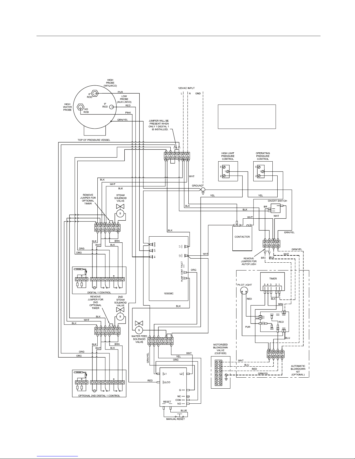
Control Circuit Wiring Diagram
Digital 1 Temperature Control System and optional automatic blowdown assembly
For Models: CU-360A to CU-750A and CU-1000AF3, CU-1250AF3, CU-1400AF3
NOTES:
1. Larger roo ms may require t wo or more
steam so lenoid val ves in parallel.
2. When generato r services two roo ms,
second roo m requires a Digital 1 and
Soleno id Valv e(s).
11
Page 12
LEGEND
___________
Factory Wiring
__ __ __ __ __
F
ield Wiring
AUXILIARY LOW WATER CUTOFF 90241MRT
mr.steam
®
CU Series Installation, Operating & Maintenance Manual
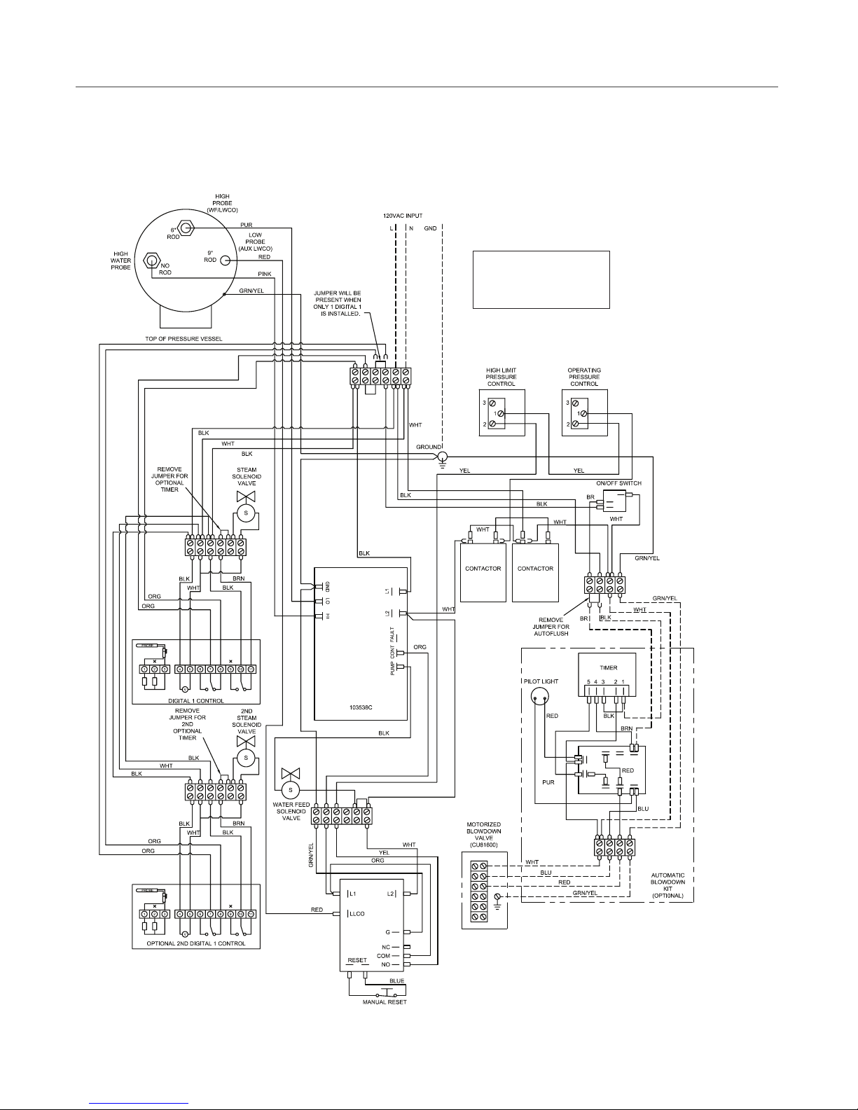
Control Circuit Wiring Diagram
Digital 1 Temperature Control System and optional automatic blowdown assembly
For Models: CU-1000AB3, CU-1000AC3, CU-1250AB3, CU-1250AC3, CU-1400AB3, CU-1400AC3
NOTES:
1. Larger roo ms may require t wo or more
steam so lenoid valves in parallel.
2. When generato r services two roo ms,
second roo m requires a Digital 1 and
Soleno id Valv e(s).
12
Page 13
mr.steam
AUXILIARY LOW WATER CUTOFF 90241MRT
®
CU Series Installation, Operating & Maintenance Manual
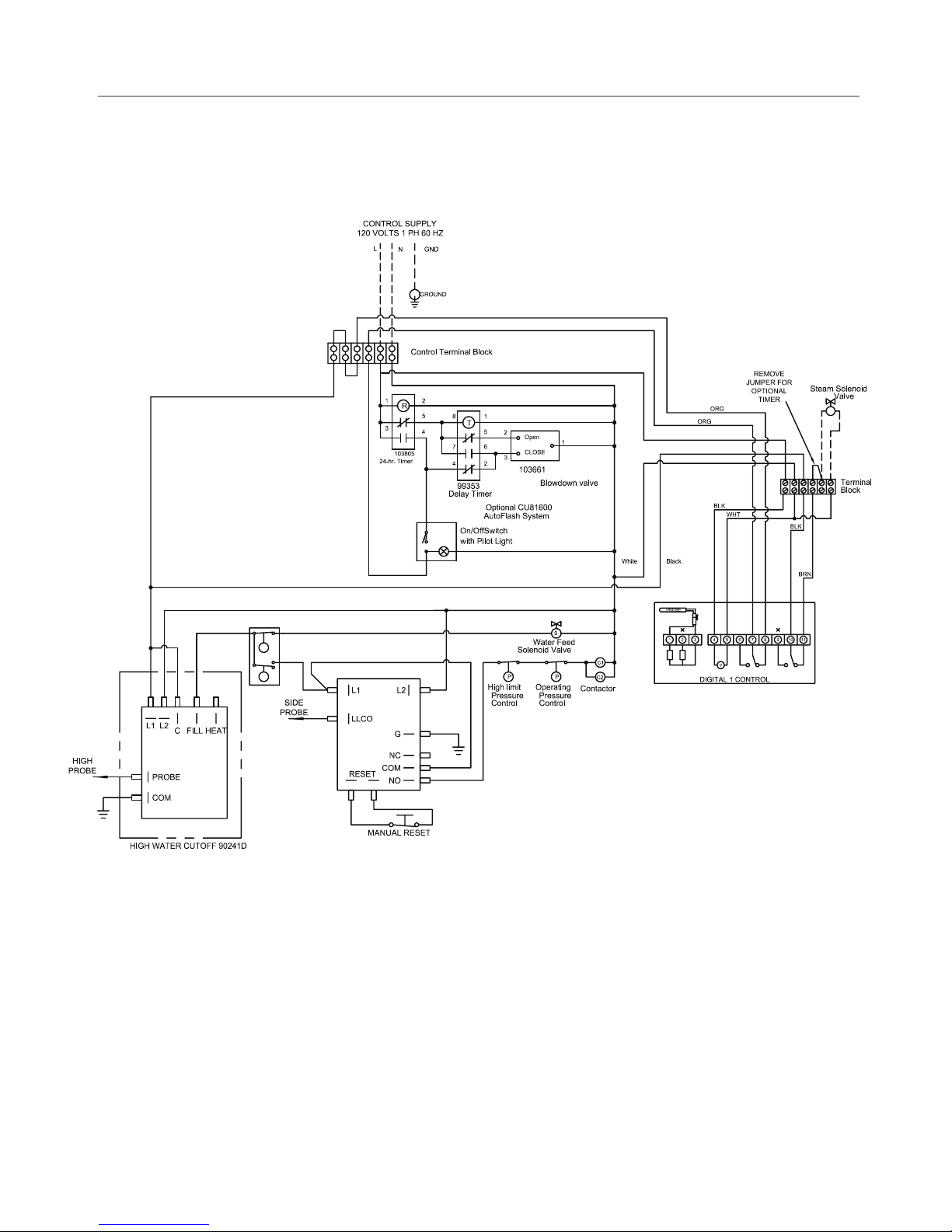
Control Circuit Wiring Diagram
Models CU-2000 and higher with Digital 1 Temperature Control System
and Optional Automatic Blowdown Assembly
IMPORTANT:
1.
Digital 1 Plus sensors are intended to be field installed within the steam
room at the location selected by the designer/architect.
DO NOT LOCATE THE DIGITAL 1 SENSORS NEAR OR ABOVE THE
STEAMHEAD(S) AS THIS MAY CAUSE DIRECT STEAM EMISSION TO
INTERFERE WITH STEAMROOM TEMPERATURE REGULATION.
2.
Autoflush System 24 hr. timer and Digital 1 operating settings are at the
discretion of the owner/operator.
IMPORTANT:
themselves with the latest edition of the instruction manual.
Owners/operators should obtain a copy and familiarize |
13
Page 14
Digital 1 Sensor
Digital 1 Control and 30 ft. Cable Acrylic Shield
3
⁄4"
Steam Solenoid Valve Digital1 Sensor Cover
3
⁄4"
Steam Head
Digital 1 Sensor
Digital 1 Control and 30 ft. Cable Acrylic Shield
3
⁄4"
Steam Solenoid Valve Digital1 Sensor Cover
3
⁄4"
Steam Head
mr.steam
®
CU Series Installation, Operating & Maintenance Manual
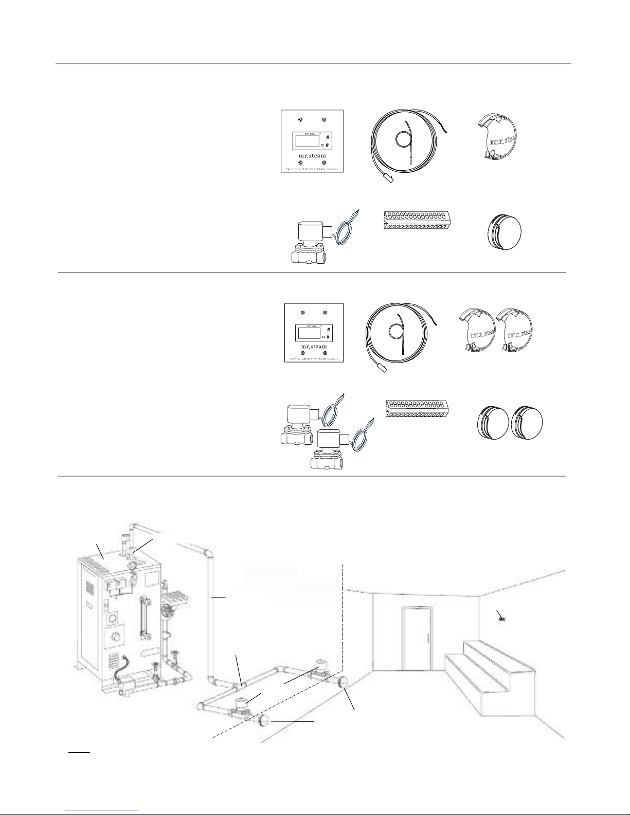
DIGITAL 1™Kit Contents
Mr. Steam CU Steambath Generator can be used for
one or two steam rooms in accordance with Page 5,
Item D. Each room requires one Digital 1 Kit sized
for the room.
See page 3 (figure 1) for typical installation.
DIGITAL 1 KIT CONSISTS OF:
• Digital 1 Control (factory installed on generator)
• Digital 1 Sensor
• One 3/4" Steam Solenoid Valves and 3/4" Steamhead
• Acrylic Shield
• Sensor Cover
CU2-Digital 1™Kit Contents
CU 2000–4500 serving one room using two steam
solenoid valves and two steamheads.
CU2-D1PLUS KIT CONSISTS OF:
• Digital 1 Control (factory installed on generator)
• Digital 1 Sensor
• Two 3/4" Steam Solenoid Valves and 3/4" Steamhead
• Two Acrylic Shields, one for each steamhead
• Sensor Cover
CU2-D1 Typical Installation
(CU2000-4500 serving one room using two steam solenoid valves and two steamheads)
Steam
Generator
1” Steam Outler
Fully Insulated
Steam Pipe
90 degree T
Digital 1 Sensor
U T I L I T Y R O O M S T E A M R O O M
NOTE: FOR ILLUSTRATIVE PURPOSES ONLY. Optional equipment shown. Consult with qualified designer,
architect or contractor for steam room construction details, including location of steam head(s) and sensors.
3
⁄4” Steam
Solenoid
3
⁄4” Steamheads
with Acrylic Shields
14
Page 15
mr.steam
®
CU Series Installation, Operating & Maintenance Manual
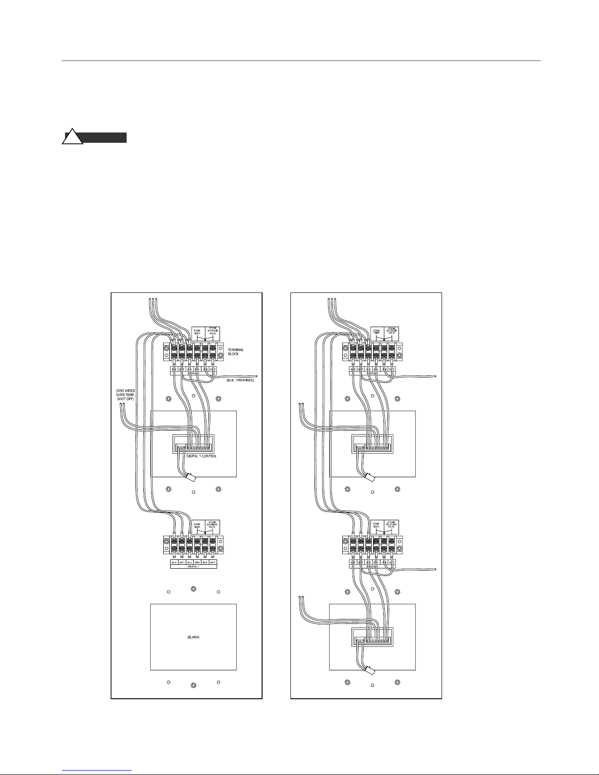
Digital 1™Control Installation
NOTE: If the stam generator came with a factory installed Digital 1control skip to page 16.
WARN I N G
!
before making wiring connections.
NOTE: Reference applicable wiring diagram.
1.
Remove 4" diameter blank cover located on steam generator. Mount the Digital 1 faceplate on the back
of the generator cabinet with provided screws and nuts. For one room installation use the upper blank.
2.
Connect the control wires to the bottom of the terminal block above the control.
The terminals are coded with the wire insulation color: Black-White-Black-Brown-Black-White.
3.
Refer to applicable schematic for proper wire connections.
Hazard of Electric Shock. Disconnect all power supplies
Control Panel Showing Control Panel Showing
One Digital 1 Control Two Digital 1 Controls
15
Page 16
S
e
n
so
r
Ca
b
l
e
3/8" hole
Silicone Sealant
(4) Mounting Screws
Bulb Guard
R
o
ut
e S
e
nso
r
C
a
b
l
e d
i
r
e
c
t
l
y
t
o
D
i
gi
t
a
l
1
C
o
nt
r
o
l
Locate approximately
5 feet above
steam room floor
Sensor
1
/2"
Front Back
CU-81600
Motorized Drain Valve
mr.steam
®
CU Series Installation, Operating & Maintenance Manual
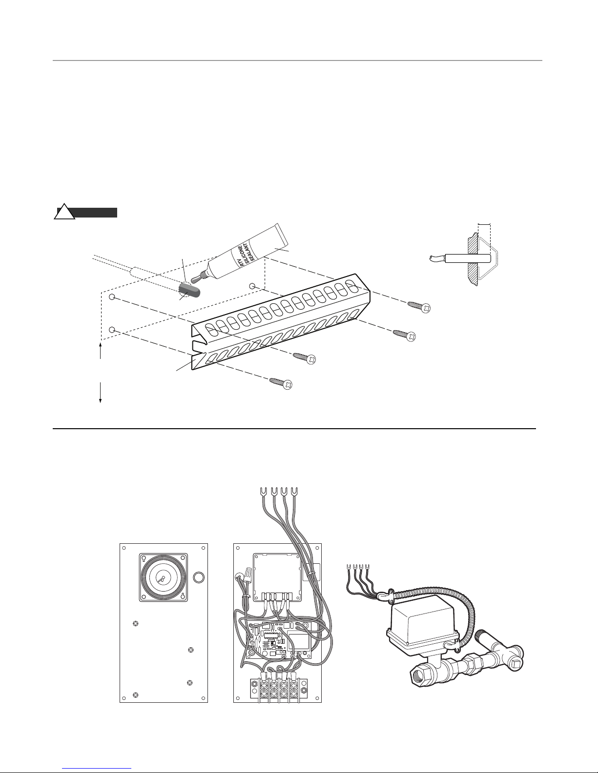
Digital 1™Operating Temperature Sensor Installation
• Locate sensor on a wall inside the steam room five (5) feet above the floor.
DO NOT LOCATE THE DIGITAL 1 SENSORS NEAR OR ABOVE THE STEAMHEAD(S) AS THIS MAY CAUSE DIRECT
STEAM EMISSION TO INTERFERE WITH STEAMROOM TEMPERATURE REGULATION.
• Route sensor cable directly to Digital 1 Control.
• Do not route sensor cable inside metal conduit.
• Do not route sensor cable with power wiring, next to electric motors or any other location subject to electrical noise.
• Seal cable entrance to steam room with silicone.
• Protect sensor with bulb guard provided.
CA U T I ON
!
Ensure all splices in the sensor cable are securely crimped soldered and
sealed with eat shrink tubing
DIAGRAM A
Automatic Blowdown System
CU 81600
The Automatic Blowdown System consists
of the following factory installed items:
• Blowdown Control Panel
• Motorized Drain Valve Assembly #CU-81600
16
Page 17
CU AUTOFLUSH
GRNWHTBLKBRN
Blowdown
Control Panel
Terminal Block
in Steam Generator
Panel Interior
Remove Jumper
mr.steam
®
CU Series Installation, Operating & Maintenance Manual
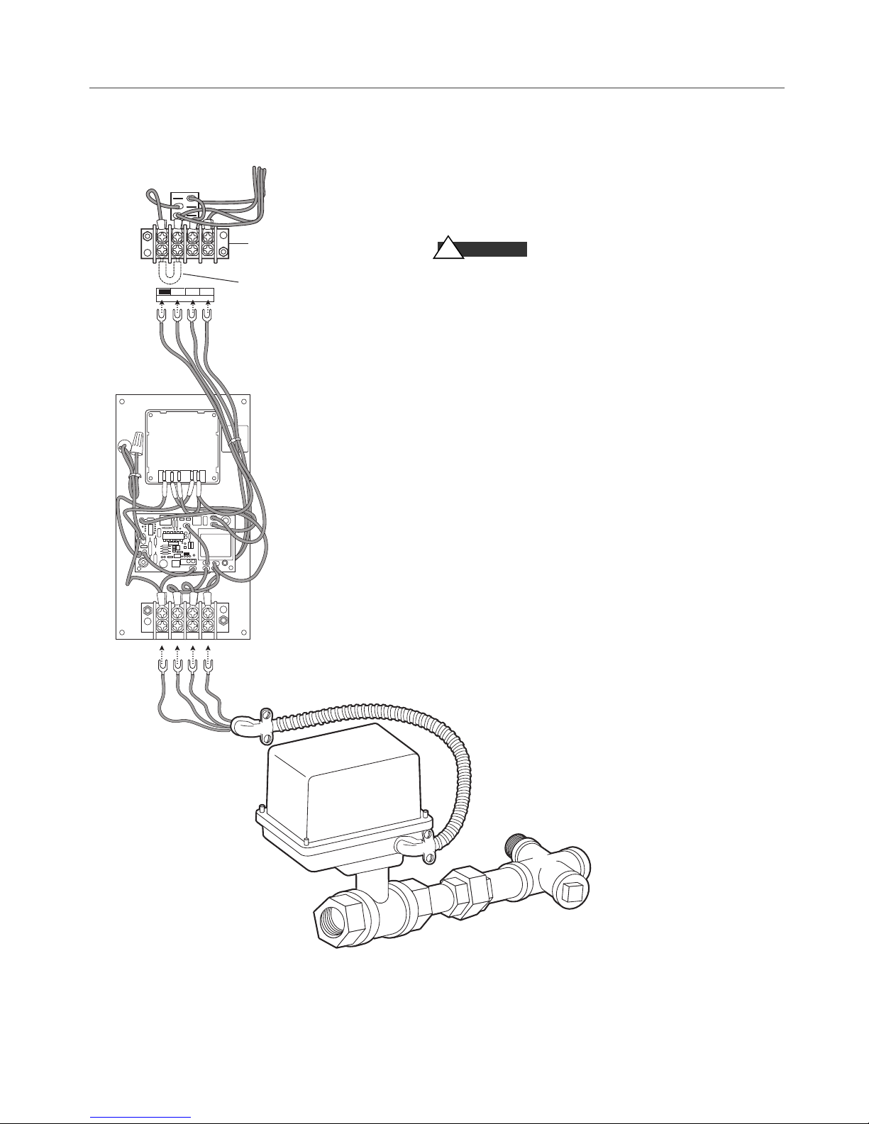
Automatic Blowdown System Kit Installation
Note:
If the steam generator came with a factory
installed Automatic Blowdown System see page 22
on how to program the timer.
WARN I N G
!
Hazard of Electric Shock.
Disconnect all power supplies before making
wiring connections.
Note:
Reference applicable wiring diagram.
1.
Remove blank cover and mount the Automatic
Blowdown Control Panel on the front of the generator cabinet with screws and nuts provided.
2.
Remove the jumper between Brown and Black from
the terminal block above the panel.
3.
Connect the wires to the terminal block.
The terminals are coded with the wire insulation
color: Brown-Black-White-Green.
4.
Plumb the motorized valve assembly to the generator drain valve.
5.
Install the valve cable in the knockout below the
Automatic Blowdown Control Panel.
6.
Connect the wires to the terminal block at the bottom of the panel. The terminals are coded with the
wire insulation color. CU81600: White-Blue-RedGreen
7.
Program the timer and set the clock (See page 24)
CU-81600 Motorized Drain Valve Assembly
17
Page 18
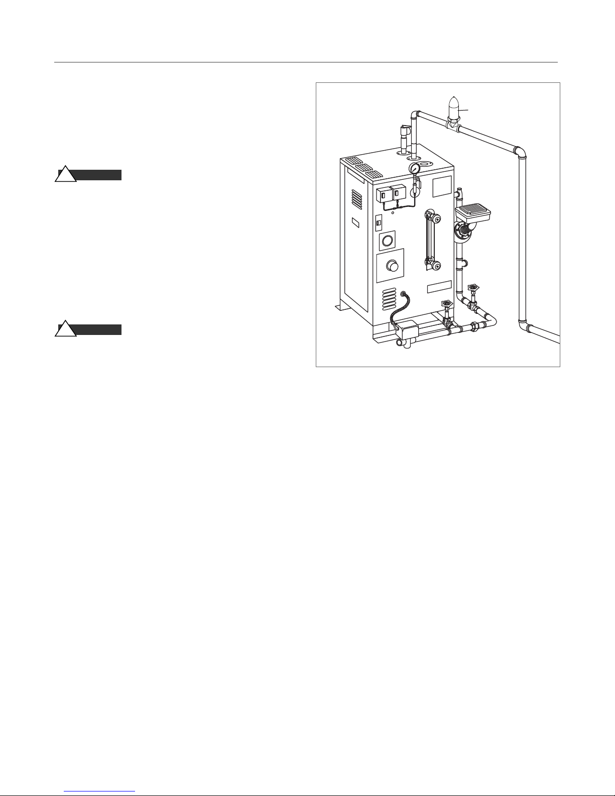
Steam Generator
Steam Vent
mr.steam
®
CU Series Installation, Operating & Maintenance Manual
30 Minute Room Timer
The 30 minute timer provides guests in the steam room an accurate and easy way to safely time their steam sessions. It is available as a Digital (CU-99216DIG) or Mechanical (CU-99216B)
timer.
1.
This timer may only be fitted by a qualified electrician.
WARN I N G
!
supply voltage. Fit the timer appropriately before connecting it
to the main supply. Never touch the live contacts or components
at the open back of the timer.
2.
Protection against touch contact must be ensured by a proper
mounting. When fitting the timer, make sure that during normal operation it is
impossible for the end user of the steam generator it was fitted
in to remove the timer by pulling it to the front and exposing
the live parts.
3.
Avoid any contact of the timer with water.
WARN I N G
!
inside the steamroom.
4.
IMPORTANT:
the steam line between the steam generator and the steam solenoid valve when using a 30 minute timer as shown.
NOTE:
See the Operating Manual for the Digital Timer (PUR
100383) for complete installation instructions.
NOTE: All drawings are for illustrative purposes only.
SHOCK HAZARD! This timer uses the specific
The 30 Minute Timers shall not be installed
A steam vent (PN 104072) must be installed in
Steam Vents
18
Page 19

mr.steam
®
CU Series Installation, Operating & Maintenance Manual
Principles of Operation
MR.STEAM CU Steambath Generators require two sources
of electrical supply – power voltage and control voltage.
Power voltage is usually 208, 240, or 480 volt, single or
three phase. Control voltage for generator suitable for operation with these voltages is 120V, 1PH.
IMPORTANT:
plate located on the outside of the boiler enclosure for rated
power and control voltages.
IMPORTANT:
trical supply requirements for your steam generator. A lighted
ON/OFF switch activates the control circuit. MR. STEAM
CU Generators are equipped with automatic liquid level/low
water cut-off control. CU360 – CU1400 are equipped with a
dual probe type electronic control. CU2000-CU4500 are
equipped with float type MM150 control (Refer to wiring
diagrams.) When there is no water in the generator, the contactor is "OFF" and the water feed solenoid valve is "ON".
The unit will start filling with water. When the water level
has reached approximately halfway up the gauge glass, the
contactor(s) will be energized and, in turn, energize the heating element(s). The water solenoid will continue to feed
water for a short time and then de-energize. Steam will be
available within a few minutes.
The generator has an electronic high water level cut-off control. If water level rises near the top of the pressure-sure vessel, the contactor(s) and the water feed solenoid valve will
de-energize to “OFF”.
When steam pressure reaches the operating pressure control
setting, the pressure control will de-energize the contactor(s).
Operating pressure control is factory set at
IMPORTANT:
be operated higher than
Steam supply to the steambath is controlled by the Digital 1
Temperature Control System and the steam solenoid
valve(s). As the room temperature selected by the
owner/operator decreases below the set point, the Digital 1
Control will energize the steam solenoid valve(s) and allow
steam to enter the steam room. Once the set temperature on
the control is reached at the sensor, the control will de-energize the steam valve, closing the valve and stopping the
flow of steam into the steam room.
In all cases, refer specifically to the boiler data
See the generator nameplate for specific elec-
5 psig.
It is recommended that the steam generator not
5 PSIG.
The Digital 1 Kit is provided with Over Temperature
Control. Digital 1 monitors the room temperature inside the
commercial steambath. If the room temperature exceeds the
set point, the Digital 1 shuts off the power to the CU
Steambath Generator, shutting steam off. CU-HL can also
send a signal to an audible alarm (CU-Alarm sold separately).
The pressure in the generator will decrease slightly as steam
leaves the generator and enters the steam room. The pressure
control will energize and de-energize the contactor(s), maintaining the set pressure. As the water level in the generator
decreases, the liquid level control will energize the water
solenoid valve on and off and maintain proper water level.
IMPORTANT:
familiarize themselves with the latest edition of the
American College of Sports Medicine Health/Fitness Faculty
Standards and Guidelines, or a similar resource and reference
publication, and refer to those guidelines for the proper and
safe operation of a spa facility including steam rooms.
The owner/operator has the responsibility to select a room
operating temperature meeting guideline requirements for
steam rooms.
Important Optional Equipment
1. Optional Automatic Blowdown System (CU81600) has a
24-hour, 7-day timer that turns the steambath generator ON
and OFF. At the end of the "ON" cycle, the boiler is automatically blown down, discharging daily accumulation of
minerals and salts which if not drained may affect steam generator performance and operation.
2. An optional control circuit transformer provides control
circuit voltage from the power supply voltage. This option
is in lieu of the need for a separate control circuit.
3. An optional Auxiliary Manual Reset Low Water Cutoff
serves as a back up to the standard liquid level control as
required in some jurisdictions.
Owners/operators should obtain a copy and
19
Page 20
mr.steam
out 1 out 2˚F
SET
®
CU Series Installation, Operating & Maintenance Manual
Automatic Blowdown Operation & Testing
NOTE:
The Time Clock controls boiler operation. The boiler is on
when the timer is on. The Blowdown Valve will open when the
timer turns the boiler off. See page 24 for Time Clock instructions
CA U T I ON
!
down, and to comply with National and local plumbing and building
Codes, it may be necessary to blowdown into an ASME Code blowdown separator tank, or to take other precautions to prevent damage
to building drain plumbing. Consult with a licensed plumber.
WARN I N G
!
is discharged during blowdown.
1.
Turn the override switch to permanent ON (I).
2. Turn the generator On/Off Switch to “ON”. On/Off Switch pilot
light and generator should be “ON”. Motorized drain valve should
be closed. Auto blowdown light should be “OFF”.
3. Turn the override switch to permanent OFF (0). On/Off Switch
pilot light and generator should be “OFF”. Auto blowdown light
should be “ON” Motorized drain valve remains open for approximately 10 seconds.
4. After 10 seconds: Motorized drain valve closes. Auto blowdown
light should be “OFF”. On/Off Switch pilot light and generator
remains “OFF”.
5. Turn the override switch to automatic
To provide for safe and low temperature blow-
Burn Hazard. Pressurized Steam and Hot Water
( ).
NOTE: ASME blowdown separator tank systems are available
from Mr. Steam. For more information please contact
Mr. Steam at 1-800-76 STEAM.
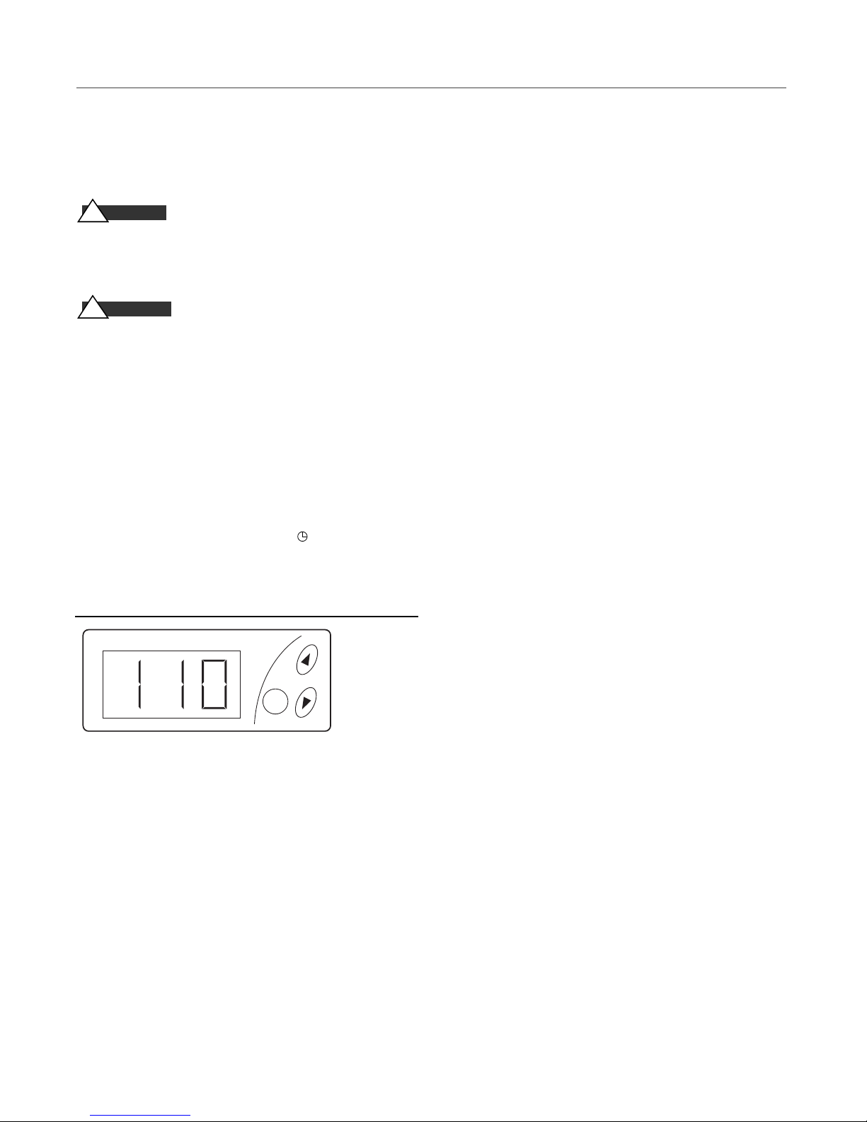
Digital 1 Control Operating Parameters
• Operating Temperature range 100 – 120 °F (37.5 – 49 °C)
• Backup Temperature shut off fixed at 130 °C (54.5 °C).
Setting Operating Temperature
1.
Press the SET button twice, the light under OUT 2 will be on
and the display will be flashing.
2.
Use the UP / DOWN arrows to set the temperature. Factory set
at 100 °F (37.5 °C).
3.
Press the SET button again; the display will be solid and showing room temperature (not pressing any button for 1 minute
will also return the control to the room temperature).
NOTE: the control display remains on if the steam bath
generator switch is in the OFF position, however power to
the solenoids will be OFF.
Operation Indicators
OUT 1:
OUT 2:
The LED under OUT 1 is on during normal operating
conditions. If the light under OUT 1 is off the Digital 1 is in
backup temperature mode, an alarm will sound, the display
will flash and the steam bath generator will be off.
The LED under OUT 2 goes on and off during normal
operating conditions. If the light under. OUT 1 is off the
room temperature is satisfied and the steam solenoid valve
will be closed. When the light under OUT 2 is on the room
temperature has not been satisfied and the steam solenoid
should be open (if a 30 minute timer is used, that must be
on to open the steam solenoid).
Backup Temperature Shut-Off
•
Digital 1 Control will shut off power to the steam bath generator.
• The display will change to a flashing AH1, and an alarm will
sound (if equipped the CU ALARM will also sound.
• To silence the Digital 1 Control Alarm press SET and DOWN
simultaneously. The alarm will be silenced but the display will
still flash AH1 and the steam bath generator will remain off.
*Note if equipped with a CU ALARM turn the steam bath genera-
tor switch off to silence it.
• The Digital 1 control will reset when the temperature in the
room reaches normal operating range.
Message Display
Under normal operation, the actual room temperature will be
displayed, the following messages may also appear (the Digital1
Control alarm will also sound, press SET and DOWN simultaneously to silence alarm, if equipped with a CU ALARM turn the
steam bath generator switch OFF to silence it, the steam bath
generator will shut off until the error is cleared):
___________________________________________________________________
• Err Memory reading error, cut power to control to clear
___________________________________________________________________
• AH1 Backup temperature alarm
___________________________________________________________________
• AL1 (AL2 ) Low temperature alarm, this may be an indication of a probe problem, check the actual room temperature
___________________________________________________________________
• ooo Open Probe, check probe connection, check probe
with multimeter
___________________________________________________________________
• - - - – Shorted probe, check any splices used, check probe
with multimeter (note: if equipped with CU STEAMSTOP,
the Digital 1 Control will display --- when the CU STEAMSTOP is pressed, reset the CU STEAMSTOP to clear)
___________________________________________________________________
NOTE: The operating room temperature setting is determined
by the owner/operator of the facility. For guidance, refer to
ASCM guidelines or equal reference.
20
Page 21
mr.steam
. Exit immediately if uncomfortable, dizzy or sleepy. Staying too long in a heated
1
rea is capable of causing overheating. Limit yourself to a maximum of ten (10)
a
inutes. High temperature and humidity can be dangerous to your health.
m
2. Children under the age of 16 should not use this facility.
. Check with a doctor before use if pregnant, diabetic, in poor health or under
3
edical care.
m
4. Breathing heated air in conjunction with consumption of alcohol, drugs
or medication is capable of causing unconsciousness. Therefore, do not use this
facility if you have recently consumed alcohol, drugs or medications.
. Do not contact steam head or steam at the steam head.
5
6. Allow yourself at least five (5) minutes after exercising to cool down before
entering this facility.
se care when entering or exiting the steam room. Floors may be slippery and
U
dangerous due to moisture. Use of proper footwear is recommended at all times.
Note: For additional safety considerations see Owners manual.
3-20 34th Street, Long Island City, NY 11101 1-800-76-STEAM www.mrsteam.com
4
®
mr.steam
CU Series Installation, Operating & Maintenance Manual
®
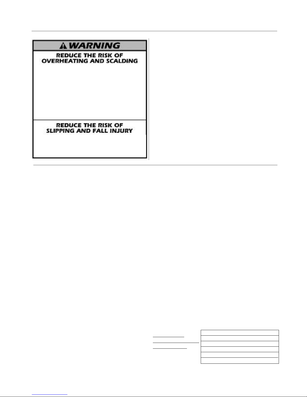
Warning Signage
The CU Steambath generator is provided with
a WARNING sign. This WARNING is to be
secured to the outside of the steam room, on
the steamroom door or adjacent to that door.
It's location must be such that all steam
bathers are readily made aware of the important
information contained in the sign.
Pre-Operation Check
Low water Cutoff (LWCO) and
Feed Control Operation and Testing
1.
All valves for incoming water supply are to be fully
opened. Main disconnect switch to be in "ON" position. Generator switch to be in “ON" position. Since
generator will be empty, water solenoid will be energized allowing the generator to fill with water until
proper level is reached. Then the contactors will energize and supply voltage to heating elements.
2.
Water level control operation: At this point the water
should be visible approximately half way up the sight
glass. Slowly open the drain valve located at bottom
of the generator. The water level will fall allowing the
low water cutoff/water level control to energize the
feed water system. Close the drain valve for proper
operation.
3.
Low water cut-out switch performance. Close water feed
valve. Open the drain valve completely. Maintain this
condition until the water level falls within the gauge
glass enough to cause the low water cutout switch to
de-energize the heating elements. All contactors will be
in the de-energized state at this time. Close the drain
valve. For automatic re-setting type low water cutoff
switches, feed system will return the water level to normal. For manual re-set the reset button must be
depressed to complete circuit. The generator is now
qualified for proper low water cutout and normal liquidlevel operating conditions.
NOTE:
For automatic blowdown, turn timer off and on
until water level is low enough to de-energize heaters.
Pressure Controls Operation & Testing
Steambath generators are provided with one hi-limit pressure control and at least one operating pressure control.
1.
All pressure controls are equipped with a screw allowing for set-
ting of the desired operational and hi-limit pressures.
2.
It is recommended that the hi-limit control be set at 8–10 psig
maximum and the operating pressure control(s) shall not be set
above 5 psig.
Note: Models CU360 - CU3000 are provided with one (1) automatic reset operating pressure control and one (1) manual reset high
limit pressure control. Models CU 4500 is provided with two (2)
automatic reset operating pressure controls and one (1) manual reset
high limit pressure control.
3.
Pressure control operation check: Manually close the steam
outlet valve. Switch the generator on to allow for steam pressure
build-up. Pressure gauge reading will build and the operating
pressure control will shut off the generator at the pressure setting. Re-setting the operating pressure control is accomplished
by manually bleeding off pressure through the steam outlet valve
and allowing the pressure to drop below the desired set point.
Torque Valves
Check to insure all element flange bolts, element terminals, and
contactor terminals are tightened to the following specifications.
IMPORTANT:
See page 28 for
additional information
and illustrations.
TORQUE VALUES
Element Flange Bo lts 22 lb-ft
Element Terminal s 20 l b-in
Contact or Terminals 50 amp 25 lb-i n
60 amp 4 5 lb-in
75 amp 7 5 lb-in
21
Page 22
mr.steam
®
CU Series Installation, Operating & Maintenance Manual
Operation
AU T I O N
C
!
switch, insure all electrical and mechanical connections are
tight before energizing unit to prevent electrical problems
and mechanical leaks.
1.
Turn on water and electrical supply, power and control
voltage suppliers. Turn unit switch to ON position;
Switch light will go ON and water level will reach operating level automatically.
2.
When proper operating level is reached (approximately
half way up the gauge glass), the heating element(s)
will be energized. In approximately 20 minutes, steam
will begin to be produced.
With all power disconnected at main
Manual Blowdown Instructions
Blowdown is an essential part of operation. It is an excellent
preventative maintenance procedure and will prolong
steambath generator operation. Insure the following recommended blowdown schedule is established and followed daily:
1.
If blowdown is conducted manually, at the end of each
working day while unit is still operating,
turn ON/OFF switch to the "OFF" position and close
water supply valve. De-energize wall-mounted safety
switch. Open blowdown valve(s) SLOWLY.
IMPORTANT:
2.
Discharge is complete when gauge glass shows no water.
Unit has been effectively drained. Follow this procedure:
a. Fully close the blowdown valve
b. Fully open water supply
c. Put ON/OFF switch in the "ON" position
d. Close wall-mounted safety switch
Pressure may still be in the generator.
3.
Adjust the Digital 1 operating temperature control to the
desired steam room setting at the sensor
(range 100°F – 120°F). Operating temperature is at the discretion of the owner/operator.
CA U T I ON
!
trol is provided with an adjustable temperature range. The
Digital 1 control will cycle automatically to maintain the room
operating temperature selected by the owner/operator
sensor at the set point temperature.
4.
If not supplied with an automatic blowdown system, the
generator must be blown manually down daily in accordance
with manual blowdown instructions below. See below.
An optional automatic blow-down assembly is recommended
for daily maintenance.
3.
When re-filling is complete (water feed solenoid valve de-energizes and water is visible to half-way level in gauge glass),
turn off generator unless further operation is required.
4.
If you have been supplied with a manual reset low water control, as required by some states, the reset button on the control
must be reset before unit will begin developing pressure. Do
not push reset until unit has filled with water.
5.
More frequent blowdowns may be required in area with hard
water or excessive usage. Please consult with factory.
CA U T I ON
!
down, and to comply with National and local plumbing and
building Codes, it may be necessary to blowdown into an ASME
Code blow-down separator tank, or to take other precautions to
prevent damage to building drain plumbing. Consult with a
licensed plumber.
For user comfort, the Digital 1 operating con-
at the
To provide for safe and low temperature blow-
NOTE: ASME blowdown separator tank systems are available
from Mr. Steam. For more information please contact Mr.
Steam at 1-800-76 STEAM.
Automatic Blowdown Instructions
Automatic Blowdown Systems drain the steambath
generator every 24 hours (or more often if required or
desired). It also turns the generator "ON" and "OFF".
Blowdown occurs after the timer turns the generator off.
The blowdown pilot light is energized during blow-down.
To set the timer, refer to instructions on inside of element
access door.
CA U T I ON
!
voids warranty.
Use of chemical cleaning compounds
CA U T I ON
!
blowdown, and to comply with National and local plumbing
and building Codes, it may be necessary to blowdown into an
ASME Code blow-down separator tank, or to take other precautions to prevent damage to building drain plumbing.
Consult with a licensed plumber.
NOTE: ASME blowdown separator tank systems are available
from Mr. Steam. For more information please contact Mr.Steam
at 1-800-76 STEAM.
22
To provide for safe and low temperature
Page 23
mr.steam
®
CU Series Installation, Operating & Maintenance Manual
Maintenance Instructions
To establish a good preventive maintenance program,
we suggest that the site equipment foreman, engineer
or owner/operator familiarize themselves with these
guidelines:
1. Daily blowdown
is recommended for best steambath generator performance. In order to safeguard the heating element(s)
within the steambath generator, the main wall switch
and the steambath generator switch shall both be
placed in the OFF position
the generator.
followed as outlined in this manual.
ical cleaning compounds in the steambath generator
since the chemical agents may damage some of the
generator components. A daily blowdown will assist
in prolonging product operation.
2. Only after electric power supplies have been
disconnected at main disconnect switch
monthly inspection should be made of all wiring. All
electrical connections should be checked for tightness.
A check for steam and/or water leaks should be made
and any loose fittings must be tightened immediately.
Check heating element flange bolts for tightness.
Specific torque in 22 Ft. lbs. cold.
3.
Generators equipped with the McDonnell-Miller control (Models CU-2000 and larger), should be checked
for proper operation
At the same time, a bottom heating element should be
removed and inspected. If scale has begun to form, all
elements should be cleaned and re-installed, using
only new gaskets and bolts. The pressure control
should also be removed to insure that the bellows has
not become clogged. (See trouble-shooting guide for
instructions.) Check valves should be inspected for
leakage and proper operation.
at max 5 PSIG operating pressure
prior to blowing down
Blowdown instruction should then be
Do not
every three months or sooner.
use chem-
, a
4.
Generators equipped with level probes (Models CU 2000 CU 1400) for maintaining operating water level and probe
for auxiliary low water cut-off protection need special consideration. The probe should be checked for chemical
deposits and cleaned as necessary. This should be done
every three months or sooner, as required by usage and/or
water quality.
The probes and probe isolators should be cleaned using the
following procedure:
a. Use emery paper to clean probes.
b. Remove the probe isolators.
c. Use a bottle brush to remove scale from the inside of the
probe isolators. Care must be taken to ensure the two holes
on the side of the probe isolators are clear.
d. Flush probe isolator thoroughly with water.
e. Use Teflon tape on probe isolator threads and reinstall.
Use Teflon tape on probe threads and reinstall.
f. After installation, make sure the probe is not touching
ground. With the generator drained and probe wires disconnected, there should be no continuity between the probe and
ground.
CA U T I ON
!
service personnel should attempt the above procedures.
Always insure all electrical power supplies are disconnected at
the main disconnect switches to prevent electric shock. Always
insure that pressure within steam generator is 0 PSIG (zero
pressure) whenever plumbing connections, including any factory-plumbed components, are being disconnected.
5. Torque Values
if required, insure all element flange bolts, element
terminals, and contactor terminals are tightened to the
following specifications.
TORQUE VALUES
Element Flange Bo lts 22 lb-ft
Element Terminal s 20 l b-in
Contact or Terminals 50 amp 25 lb-i n
Under any circumstances,
Every two months or more frequently
60 amp 4 5 lb-in
75 amp 7 5 lb-in
only qualified
IMPORTANT: See page 28 for additional information
and illustrations.
23
Page 24
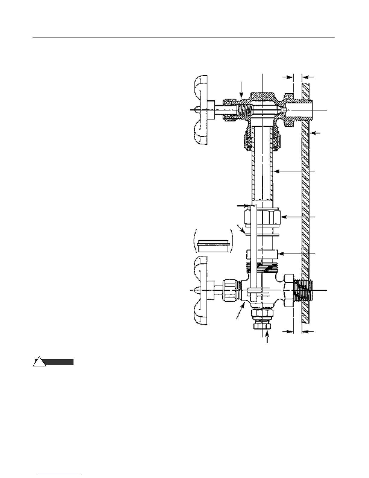
mr.steam
®
CU Series Installation, Operating & Maintenance Manual
Water Gauge & Gauge Glass Installation
IMPORTANT:
maintain water gauge glass and connections. Pressure in generator must be at zero before proceeding. Remember to wear safety
gloves and glasses during installation. Before installing, make
sure all parts are free of chips and debris.
1. Apply Teflon tape or pipe dope to pipe threads. Install top
gauge fitting (fitting without a drain valve) into the upper
most tapping. Wrench tighten the fitting until it is snug and
the glass outlet is pointing at five o'clock (about1⁄ 8 turn from
its final downward vertical position).
2. Install the bottom gauge fitting (the fitting with a drain valve)
until it is snug and the glass outlet is pointing directly
upward. Verify top and bottom fittings are threaded into the
tapping the same number of turns (distance A = distance B).
3. Remove glass packing nut, friction washer (or packing gland,
depending upon the model), and glass packing from the fittings, and place them, in the same order, on to both ends of the
gauge glass. Push both packings about an inch up the gauge
glass.
4. Gently insert one end of the glass into the top gauge fitting.
Keeping the glass inside the top fitting, gently rotate the top
gauge fitting clockwise until vertically aligned with the bottom gauge, then insert glass into bottom fitting until glass
bottoms out on the shoulder inside the bottom fitting.
5. Carefully raise glass about1⁄ 16" and slide lower glass pack-
ing down until the glass packing contacts the lower gauge fitting. DO NOT allow the glass to remain in contact with any
metal!
6. Carefully slide upper glass packing up as far as possible.
7. Hand tighten both glass packing nuts, then tighten 1/2 turn
more by wrench. Tighten only enough to prevent leakage. DO
NOT OVER TIGHTEN! If any leakage should occur, tighten
slightly, a quarter turn at a time, checking for leakage after
each turn.
IMPORTANT:
performing installation or maintenance.
!
worn at all times when working with or examining
water gauge glass and connections.
Only properly trained personnel should install and
Read all warnings and instructions before
WARN I N G
Safety glasses and gloves should be
Top Gauge
Fitting
Guard Rail
Friction Washer
(or Packing Gland)
Bottom
Gauge Fitting
A
Vessel Wall
Gauge
Glass
Glass
Packing
Nut
Glass
Packing
B
Drain
Valve
Pressure in generator to be at zero before proceeding.
Improper installation or maintenance of gauge glass
and connections can cause immediate or delayed
breakage resulting in bodily injury and/or property
damage.
24
Page 25
mr.steam
®
CU Series Installation, Operating & Maintenance Manual
Water Gauge & Gauge Glass
Use and Care
DO NOTs
DO NOT use glass if it contains any scratches, chips, or any
other visible signs of damage.
DO NOT reuse any tubular glass or glass packings.
DO NOT subject gauge glass to bending or torsional stresses.
DO NOT over tighten glass packing nuts.
DO NOT allow glass to touch any metal parts.
DO NOT exceed the recommended pressure of the gauge or
gauge glass.
DO NOT clean the gauge or gauge glass while pressurized or
in operation.
DOs
DO verify proper gauge has been supplied.
DO examine gauge glass and packings carefully for damage
before installation.
DO install protective guards and utilize automatic ball checks
where necessary to help prevent injury in case of glass
breakage.
DO inspect the gauge glass daily, keep maintenance records,
and conduct routine replacements.
DO protect glass from sudden changes in temperatures such
as drafts, water spray, etc.
MAINTENANCE
Examine the gauge regularly for any signs of clouding,
scratching, erosion, or corrosion. The glass should be inspected daily until the need for replacement becomes apparent.
This will help establish the routine inspection and routine
replacement schedules.
CLEANING
Use commercial non-abrasive glass cleaners to keep glass
clean. Use diluted acids such as Hydrochloric (muriatic) acid
when regular cleaners do not seem to work. Do not use wire
brushes or any other abrasive materials which could scratch
the glass.
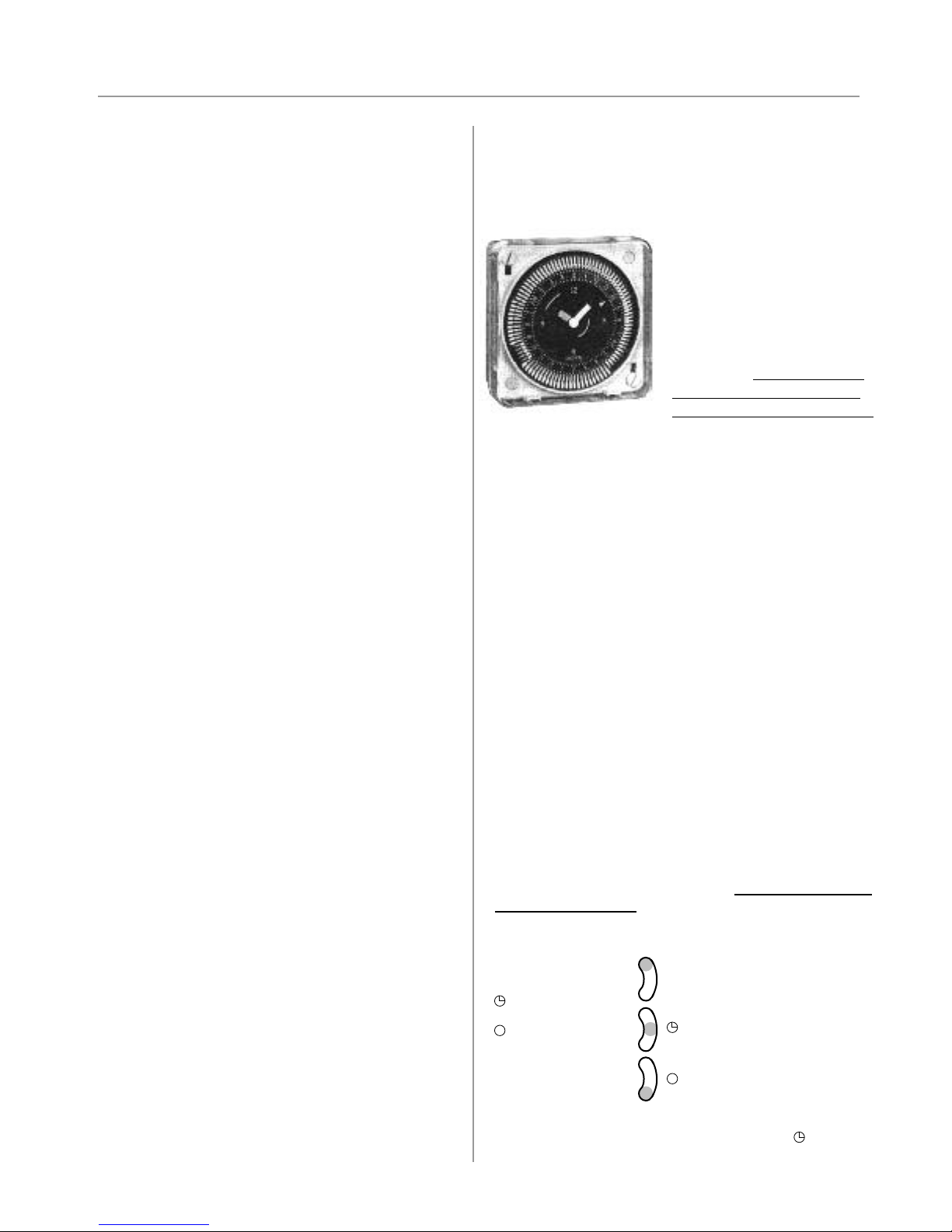
24-Hour and 7-day Time Switches
NOTE:
The Time Clock controls boiler operation. The boiler
is on when the timer is on. The Blowdown Valve will open
when the Timer turns the Boiler off.
PROGRAMMING
For CU steam bath
generators equipped with
Automatic Blowdown Systems
CU 81500 and CU 81600, refer
to the following instructions
for time clock operation
and settings. Timer settings for
blowdown operation are at the
discretion of the owner/operator.
The weekly program dial shows the seven days of the week
and AM/PM imprints for each day.
The time switch is set by pushing the captive trippers to the
outer ring position for the entire period that the load is to be
turned ON, i.e., 2 hours to each tripper on the 7-day dial.
When the tripper is pushed to the inside, the switch is in the
OFF position.
SETTING TIME
To set the current time and day of week, turn the
minute hand clockwise. Do not set the time by
rotating “Outer” Dial.
Turn the minute hand clockwise until the day of the week
and the time of day on the outer dial is aligned with the triangle marker on the inner dial (two o'clock).
Example for 7-day program dial Monday 10:30 AM. Turn
the minute hand clockwise until Monday 10:30 AM is
aligned with the triangle on the inner dial. The hour and
minute hand will show exactly 10:30.
FOR MANUAL OVERRIDE
Manual override can be accomplished
the owner/operator
as follows.
at the discretion of
INSPECTION
Examine the surface of the glass for scratches, corrosion,
chips, cracks, surface flaws, or nicks. To do this, shine a very
bright concentrated light at an angle of about 45 degrees. A
defective glass will glisten as the light strikes imperfections.
Glass which appears cloudy or roughened, and will not
respond to cleaning, should be replaced.
STORING
Keeping gauge glass in original packaging until ready to
install.
3-WAY MANUAL OVERRIDE SWITCH
I = permanent ON
= automatic
= permanent OFF
IMPORTANT:
tive blowdown,the override switch be set in the automatic
setting.
25
It is recommended that for periodic and effec-
I
Page 26

mr.steam
Trouble Shooting
®
CU Series Installation, Operating & Maintenance Manual
CA U T I ON
!
________________________________________________________________________________________________________
_
Problem Probable Cause Suggested Remedy
_________________________________________________________________________________________________________
No water in generator Water supply is "OFF" Turn on water supply
To prevent risk of electric shock, trouble shooting should be done only by a qualified licensed electrician
________________________________________________________________________________________________________
Clogged strainer Clean or replace strainer screen
________________________________________________________________________________________________________
Control voltage disconnected Restore control voltage
_______________________________________________________________________________________________________
_
Defective ON/OFF control switch Check/replace control switch
_______________________________________________________________________________________________________
_
Defective water solenoid valve Check/replace water solenoid valve
________________________________________________________________________________________________________
Defective PC Board Check/replace PC Board
________________________________________________________________________________________________________
Water feed probe not functioning Check/replace water feed probe (Models 360-1400) and
_______________________________________________________________________________________________________
_
_________________________________________________________________________________________________________
Generator does not heat Power supply disconnected Restore power supply
_________________________________________________________________________________________________________
Clogged isolator tube Check/replace isolator tube (models 360-1400)
________________________________________________________________________________________________________
No water in generator See above
________________________________________________________________________________________________________
Hi-Limit pressure control tripped Clean out syphon tube & reset pressure control
________________________________________________________________________________________________________
LWCO not functioning Check/replace LWCO probe
________________________________________________________________________________________________________
Defective contactor Check/replace contactor
________________________________________________________________________________________________________
Defective pressure control Check/replace control switch
________________________________________________________________________________________________________
Defective PC Board Check/replace PC Board
________________________________________________________________________________________________________
Defective heating element Check/replace heating element
probe isolator and/or MM150 (Models CU2000 & higher)
Contactor chatters Defective PC board Check/replace PC Board
_________________________________________________________________________________________________________
Generator floods Water feed solenoid Reverse solenoid connection
installed backwards CU 360-1400 Port “1” towards generator;
2" towards water supply
________________________________________________________________________________________________________
Defective water solenoid valve Check/replace water solenoid valve
________________________________________________________________________________________________________
Defective PC Board Check/replace board
________________________________________________________________________________________________________
CU2000 and larger, “IN” port towards water supply
Water feed probe (Models 360-1 400) Check/replace water feed probe
not functioning and isolator
________________________________________________________________________________________________________
Clogged isolator tube Check/replace isolator tube (models 360-1400)
________________________________________________________________________________________________________
MM 150
(Models CU 20 00 and higher)
Clean out pipes under MM 150
is clogged Equalizing piping and float chamber
_________________________________________________________________________________________________________
CU81600 rotates twice Jumper in (X) BRN & BLK Check/remove jumper (page 18)
terminals not removed
_________________________________________________________________________________________________________
26
Page 27

mr.steam
Check
®
CU Series Installation, Operating & Maintenance Manual
PC Board - Models CU 360, CU 500, CU 750,
CU 1000, CU 1400
CA U T I ON
!
1. Prior to checking boiler disconnect boiler electric power
supplies at main safety switch or fuse panel. Turn the
boiler switch OFF.
2. Turn the control voltage ON and turn the boiler switch
ON. Measure the voltage across "L1" and "L2" on the
103538C board. The voltage should be approximately
110 VAC.
3. On the 103538C board, disconnect the wire from the
"LO" terminal and check the voltage across "L2" and
"PUMP". The voltage should be approximately 110 volts
(same as "L1" and "L2"). Connect a jumper between the
"LO" and "GND" terminals. The voltage between "L2"
and "PUMP" should be zero.
4. On the 103538C board, disconnect the wire from the
"LO" terminal. There should be no voltage between the
"L2" and "CONT” terminals. Connect the jumper
between the "LO" and "GND" terminals. The voltage
between "L2" and "CONT" should be 110V.
________________________________________________
Low Water Cutout, Water Feed and
High Water Cutout Probes
Models CU-360 through CU-1400 are equipped with two
probes for low water cut-off (LWCO) and water feed control. Failure to clean the probes may result in generator not
operating, overflow or element failure.
CA U T I ON
!
bath generator and release pressure to zero (0 psig)
before removing probes.
1.
Probes are located in the top of the generator. Remove
covers and disconnect wires from probes. Note wire connections.
2.
Remove probes using a standard spark plug wrench.
Care should be taken not to damage the insulation.
3.
Check probes for deposits. Use emery cloth to clean
probes.
4.
Remove and flush probe isolator (thoroughly) with
water. If clogged, use a long piece of wire to remove
obstruction.
Replace if necessary, center probe rod in isolator tube.
5.
Use teflon tape on probe threads and reinstall.
6.
After installation, make sure probe is not touching
ground. With generator drained and probe wires
disconnected, there should be no resistance (X) between
probe and ground. Check for leaks.
7.
To test AUX LWCO, press and hold the manual reset
button on the side of the steam bath generator for 5
seconds.
Turn off all power supplies to steam
Steam Solenoid Valve
1.
Check voltage rating of solenoid valve (120 VAC for
United States, Canada, Mexico; may be 220-240 VAC
for other countries).
2.
Check voltage across solenoid coil.
a. If there is voltage across coil and valve does not
allow passage of steam, check for clogged valve.
Clean outline with bottle brush. If solenoid valve is
still malfunctioning, the valve is defective and should
be replaced.
b. If there is no voltage across coil, check room temper-
ature control.
c. There wull be a red dot under “OUT2” on the
Digital 1 Control when there is a call for heat.
d. Ensure, if equipped, the room Timer is On.
_______________________________________________
Digital 1 Control and Sensor:
Consult Factory
_______________________________________________
Heating Element
IMPORTANT: Turn off all power at circuit breaker.
Consult factory for resistance values.
1.
Check power voltage across heating element terminals.
Refer to nameplate data for voltage rating.
Voltage should be as marked on nameplate.
2.
Using an ammeter, measure total current draw as per
nameplate rating. (See also Amperage Chart, page 8.
Each leg should register about the same current reading.
3.
If there is more than one heating element, check
amperes of each element. Each leg of the same element
should register about the same reading for that element.
Reading may be different from other elements
due to KW (Kilowatt) rating of individual heating element.
4.
Check heating element for resistance values. Consult
factory for the resistance values for the element specifications.
CA U T I ON
!
boiler from electric power supply at main safety switch
or fuse panel. Turn boiler switch to OFF.
Prior to checking boiler disconnect
27
Page 28
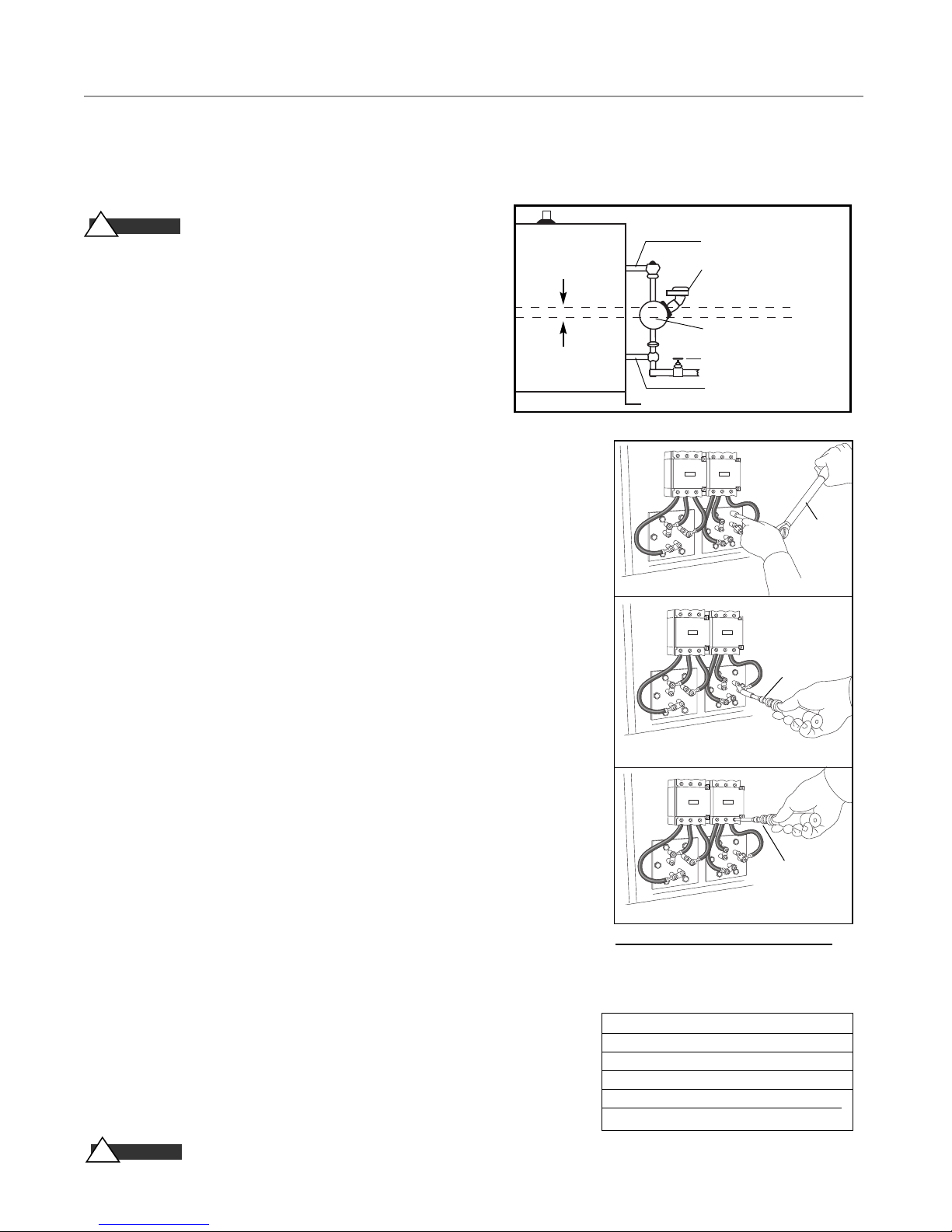
mr.steam
®
CU Series Installation, Operating & Maintenance Manual
Instructions for Element Replacement
READ INSTRUCTIONS COMPLETELY BEFORE STARTING WORK
AU T I O N
C
!
McDonnell Miller low water cut-off and aux. low water cutoff (if
supplied) is operating properly. The float chamber and lower
equalizer column of the MM control must be completely clear of
sludge or other foreign matter. Failure to do this may cause the
immediate burn-out of the new elements. If the unit is probe
equipped, check condition of the probes and isolator.
All elements are thoroughly checked before shipment. The manufacturer cannot be responsible for burn-outs caused by a faulty
low water cut-off.
The lower equalizer column can best be examined by breaking the unions on either
side and then visually and manually examining the piping with your finger or probes
to see if it is clear and clean.
IMPORTANT:
control. Model CU 2000 and higher use McDonnell-Miller MM 150.
1.
Disconnect boiler from electric power supply at main safety switch or fuse panel.
Then turn boiler switch to “OFF" position.
2.
Close water supply valve on incoming water supply line.
Drain boiler completely of water.
3.
Open boiler door to access heating element.
4.
Disconnect wire (electric) leads connecting element to main power
system of boiler. Again, note wire connections to facilitate re-assembly.
Proceed to remove and discard (6) bolts from flange.
IMPORTANT:
schematic). Remove and discard six (5/16"-18) bolts from flange.
Do not reuse these bolts.
5.
Thoroughly clean boiler flange of all foreign material.
Be certain no part of old gasket remains on flange.
6.
Apply "Slic-Tite" Gasket Compound (or equal) to both surfaces of new gasket
supplied with replacement element. Proceed to install element flange assembly
with gasket between boiler flange and element flange. In doing this, be careful to
align flange holes so element wire connection terminals on element assembly are
in line with previously disconnected wire leads to facilitate easy connections.
NOTE:
10.
11.
12.
Observe markings on element flange. Install element marking “TOP” on top.
7.
Use only new element flange bolts. Tighten all (6) element flange bolts to a
torque value of 22 lb-ft each (see illustration).
8.
Connect all wires to the terminals. Tighten all element terminals to a torque
value of 20 lb-in each (see illustration). Make sure all wires are clean and
bright to assure good electrical contact.
9.
Check that the wires are correctly connected to the contactor terminals and are
tightened to a torque value of 45 lb-in. (see illustration). Make sure all wires
are clean and bright to assure good electrical contact.
Open water valve to allow water supply to reach boiler feed mechanism.
As boiler automatically refills, observe the new flange assembly for possible
leaks. If water is noticed, the bolts must be re-tightened. Before doing this,
turn the boiler off at the main fuse safety switch.
When boiler reaches working pressure, check flange assembly again for leaks.
CA U T I ON
!
Before Installing your new elements be sure
Boiler with
McDonnell Miller
Models CU 360 - CU 1400 use probes for liquid level sensing and
Note the wire connections to facilitate re-assembly (see wiring
Avoid use of chemical cleaning compounds.
Follow maintenance instructions provided with the boiler.
11⁄2”
1” Steam Equalizing Pipe
Pump and Low Water Control
Normal Boiler Water Line
Cut-Off Level is Arrow Mark
Blowdown Valve
1” Water Equalizing Pipe
Torque Values:
Torque
Wrench
Element Flange Bolts: 22 lb-ft
Torque
Wrench
Element Terminals: 20 lb-in
Torque
Wrench
Contactor Terminals: See Torque Chart
For Illustrative Purposes Only.
Power wiring shown in approximate factory-installed location
TORQUE VALUES
Element Flange Bo lts 22 lb-ft
Element Terminal s 20 l b-in
Contact or Terminals 50 amp 25 lb-i n
60 amp 4 5 lb-in
75 amp 7 5 lb-in
28
Page 29
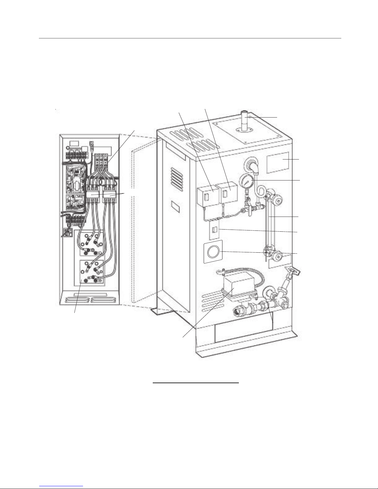
Operating
Pressure
Control
Steam Outlet
Terminal
Block
Hi-Limit
Pressure
Control
Data Plate
Pressure
Gauge
Heating Elements
Motorized
Drain Valve
Gauge Glass
On/Off Switch
24hr/7day
Blowdown Clock
Contactors
mr.steam
®
CU Series Installation, Operating & Maintenance Manual
CU 360-CU 1400 Typical Component Arrangement
For Illustrative Purposes Only.
29
Page 30
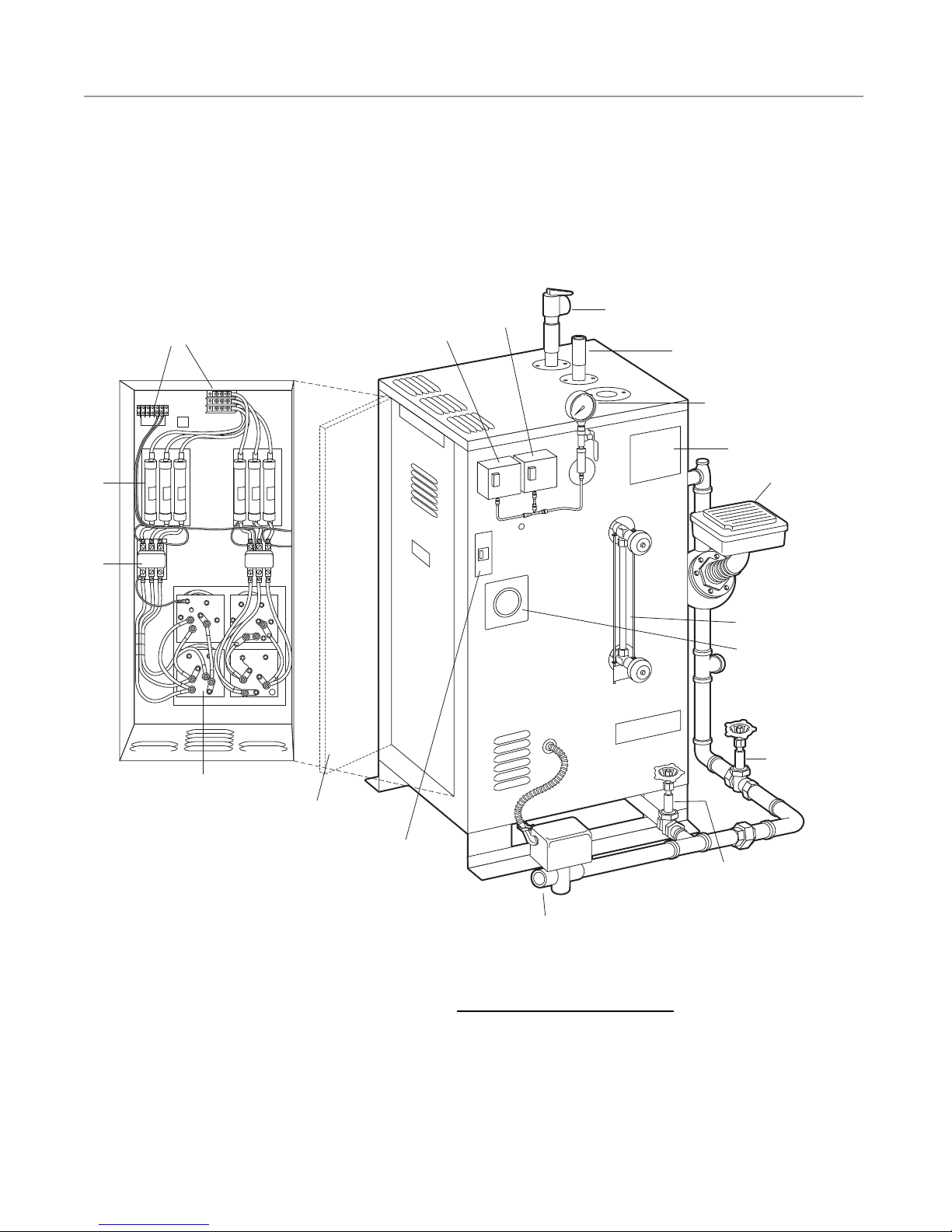
Drain Valve
Operating
Pressure
Control
Steam Outlet
Access
Door
Contactor
Terminal
Block
Fuses
Hi-Limit
Pressure
Control
Pressure
Relief Valve
Data Plate
Float-type
Liquid Level
Control
Pressure
Gauge
24hr/7day
AutoFlush
Blowdown Clock
(optional)
Heating
Elements
Drain Valve
Motorized AutoFlush
Blowdown Valve
On/Off
Switch
Gauge Glass
mr.steam
®
CU Series Installation, Operating & Maintenance Manual
CU 2000-4500 with Digital 1, Clock and Blowdown
For Illustrative Purposes Only.
30
Page 31

mr.steam
®
CU Series Installation, Operating & Maintenance Manual
Commercial Steambath Replacement Parts Models CU 360 – CU 4500
____________________________________________
PART # DESCRIPTION
____________________________________________
BLOWDOWN
____________________________________________
99353 Time Delay Relay Board
____________________________________________
102470 Blowdown Valve V for
____________________________________________
103661 Blowdown Valve V for
____________________________________________
103805 MIL 72* Blowdown Timer
____________________________________________
103662 Digi 20* Blowdown Timer
____________________________________________
CONTACTORS
____________________________________________
99003 50A 3 Pole 120V 50/60
____________________________________________
99006B 50A 4 Pole 120V 50/60
____________________________________________
99075 60A 3 Pole 120V 50/60
____________________________________________
102206-1 75A 3 Pole 120V 50/60
____________________________________________
CONTROLS
____________________________________________
104066 Digital 1 Board 120V
____________________________________________
104066C Digital 1 Board 240V
____________________________________________
104067-1 Sensor Only for Digital 1 with Guard
____________________________________________
CU-104066 Digital 1 Field Kit 120V (with Sensor
____________________________________________
CU-104066C Digital 1 Field Kit 1240V (with Sensor
____________________________________________
CU-99216B CU-30 Minute Mechanical Timer
____________________________________________
CU-99216DIG Digital Timer
____________________________________________
ELECTRIC
____________________________________________
90229 Probe Spark plug (1) for each Rod
____________________________________________
92830 ON/OFF Switch
____________________________________________
99207 Terminal Block 150 AMP 3 Pole
____________________________________________
99524-6T 18" #6 Wire with Terminal - for Heating
____________________________________________
99807B
____________________________________________
99807C
____________________________________________
103538C Level Control PC Board CU360-CU1400
____________________________________________
103538-240 240 Volt Level Control PC Board
____________________________________________
100378 Probe Isolator
____________________________________________
90229-1 AUX LWCO probe assembly
____________________________________________
90241MRT Aux LWCO Board
____________________________________________
90241N Aux HWCO Board
____________________________________________
92829 Aux LWCO Pilot Light
____________________________________________
CU81500-Soft Water
CU81600-Heavy Duty
+ Board, Guard, Cable)
+ Board, Guard, Cable)
Element
1
⁄4" x 9" Probe Rod Stainless**
CU360-CU750-Low Water
1
⁄4" x 6" Probe Rod Stainless**
CU360 - CU750-Hi Water
w/SN having an "A" Suffix, ie AXD-####A
CU360-CU1400
w/SN having an "A" Suffix, ie AXD-####A
ELECTRIC
_________________________________________________
99348 AUX LWCO RESET BUTTON
_________________________________________________
99315 Fuse Block 208/240V
_________________________________________________
99314 Power Fuses 208/240V 60A 250V
_________________________________________________
99317 Fuse Block 480V
_________________________________________________
99316 Power Fuses 480V 60A 600V
_________________________________________________
CU99331B Control Voltage transformer 208V to 120V
_________________________________________________
CU99331C Control Voltage transformer 240V to 120V
_________________________________________________
CU99331F Control Voltage transformer 480V to 120V
_________________________________________________
99580 Terminal Block 4 Pole
_________________________________________________
99593 Terminal Block
_________________________________________________
ELEMENTS
_________________________________________________
39121B 12 KW 208V 1PH
_________________________________________________
39121C 12 KW 240V 1PH
_________________________________________________
39123B 12 KW 208V 3PH
_________________________________________________
39123C 12 KW 240V 3PH
_________________________________________________
39123F 12 KW 480V 3PH
_________________________________________________
39181B 18 KW 208V 1PH
_________________________________________________
39181C 18 KW 240V 1PH
_________________________________________________
39183B 18 KW 208V 3PH
_________________________________________________
39183C 18 KW 240V 3PH
_________________________________________________
39183F 18KW480V3PH
_________________________________________________
99088 Gasket Compound
_________________________________________________
99096 Gasket 4
_________________________________________________
103540 Gasket Kit (includes gasket, hardware & bolts )
_________________________________________________
GAUGE GLASS
_________________________________________________
99074-1 Gauge glass with 2 Gaskets (CU360 - 750)
_________________________________________________
99080-1 Gauge glass with 2 Gaskets (CU1000 - CU1400)
_________________________________________________
99081-1 Gauge glass with 2 Gaskets (CU4500)
_________________________________________________
99174CV Gauge Glass 0-Ring Gasket-Viton Washer
_________________________________________________
99173C Gauge Glass Valve Set less Tube & Rods
_________________________________________________
MECHANICAL FEEDER
_________________________________________________
99114 Mechanical Low Water Cutoff & Feeder
_________________________________________________
99120 2 Wire Mercury Switch
_________________________________________________
99121 3 Wire Mercury Switch
_________________________________________________
103914 Micro Switch Assy
_________________________________________________
SA150-14 Head Gasket
_________________________________________________
SA150-106R Bellows Assembly w/Gasket
_________________________________________________
SA150-11 Float Rod & Ball Assembly
_________________________________________________
*Both MIL 72 and DIGI 20 BLOWDOWN TIMER S are available
for surface mounting. Add suffix "K" to Part Num ber
**Also CU1000 -1400 w/SN beginning with "AX"
(cont.)
1
1
⁄2" DIA.
Gauge glass with 2 Gaskets (CU1000 -1400)
(SN beginning with "AX")
(SN beginning with "N")
Gauge glass with 2 Gaskets (CU2000 - CU3000)
(mm 1 50)
31
Page 32

mr.steam
®
CU Series Installation, Operating & Maintenance Manual
Commercial Steambath Replacement Parts Models CU 360 – CU 4500
__________________________________________________
PART # DESCRIPTION
__________________________________________________
WATER FEED & STEAM SOLENOIDS
__________________________________________________
99031
__________________________________________________
99032
__________________________________________________
99042
__________________________________________________
99042C
__________________________________________________
99284A Low Pressure Steam 120V 1"
__________________________________________________
99285A Low Pressure Steam 120V
__________________________________________________
99284B Low Pressure Steam 240V 1"
__________________________________________________
99285B Low Pressure Steam 240V
__________________________________________________
99286A Low Pressure Steam 120V
__________________________________________________
PRESSURE CONTROL
__________________________________________________
99113R Operating Pressure Control 0-15 PSIG
__________________________________________________
99290 Pressure Gauge 0-30 PS
_________________________________________________
99969R HI-LIMIT Ccontrol w/Manual Reset 15PSIG
__________________________________________________
FB023 Pigtail
__________________________________________________
VALVES
__________________________________________________
99123 Strainer
__________________________________________________
99162 Spring Check Valve
__________________________________________________
99167 Spring Check Valve
__________________________________________________
99178 Valve
__________________________________________________
99182 Valve Gate Valve
__________________________________________________
99184 Valve Gate Valve 1 Steam
__________________________________________________
99297 15 PSIG Safety Valve
__________________________________________________
MISC. PARTS
__________________________________________________
103984PC Steam Head -
__________________________________________________
103985 Acrylic Shield
__________________________________________________
CU-99216B 30 Minute Mechanical Timer
__________________________________________________
CU-99216DIG 30 Minute Digital Countdown Timer
___________________________________________
1
⁄2" 120V
CU1000-CU1400 (SN beginning with "N")
CU2000-CU4500 (all)
1
⁄2" 240V
CU1000-1400 (SN beginning with "N")
CU2000-CU4500 (all)
1
⁄
" 120V
4
CU360-CU1400 (SN beginning with "AX")
CU360-CU750 (SN beginning with “DP”)
1
⁄
" 240V
4
CU360-CU1400 (SN beginning with "AX")
CU360-CU750 (SN beginning with “DP”)
1
⁄2"
1
⁄2"
3
⁄
"
4
CU 360-1400 (SN beginning AX 3197)
CU 2000-4500 (SN beginning N4-18455)
1
⁄
" NPT 180°
4
1
⁄2 inch
3
⁄
"
8
CU1000-1400 (SN beginning with "N")
CU2000-CU4500 (all)
1
⁄2"
CU360-CU1400 (SN beginning with "AX")
CU360-CU750 (SN beginning with "DP")
1
⁄2 Steam Ball
3
⁄
Steam
4
3
⁄
"
4
3
⁄4" Polished Chrome
32
 Loading...