

mr. steam CU-360, CU-500, CU-750, CU-1000, CU-1250 Maintance Manual
...
CU Series Steambath Generators
Installation, Operation & Maintenance Manual
Models: CU-360 through CU-4500
_________________________________________
IMPORTANT: LEAVE THIS MANUAL WITH THE OWNER/OPERATOR
_________________________________________
Table of Contents
Before Installing . . . . . . . . . . . . . . . . . . . . . . . .2
Steam Room Guidelines . . . . . . . . . . . . . . . . . .2
Locating the Steambath Generator . . . . . . . . . . . .3
Dimensional & Clearance Specifications . . . . . . .4
Selecting the Steambath Generator . . . . . . . . . . .5
Installation: Plumbing, Water Supply, Steam Line,
Drain, Safety Valve . . . . . . . . . . . . . . . . . . . .6
Water Quality Information . . . . . . . . . . . . . . . . . .6
Steam Room Guidelines . . . . . . . . . . . . . . . . . . .7
Steam Head & Acrylic Shield . . . . . . . . . . . . . . .7
Electric . . . . . . . . . . . . . . . . . . . . . . . . . . . . . .8
Wiring . . . . . . . . . . . . . . . . . . . . . . . . . . . . . .9
Control Circuit Wiring Diagrams . . . . . . . . .10-13
Digital 1 Control: Contents . . . . . . . . . . . . . . . .14
Control Installation . . . . . . . . . . . . . . . . . . .15
Temperature Sensor Installation . . . . . . . . . . .16
Automatic Blowdown System
Contents . . . . . . . . . . . . . . . . . . . . . . . . . .16
Installation . . . . . . . . . . . . . . . . . . . . . . . . .17
Auxiliary Manual Reset Low Water Cutoff . . . . . .18
Principles of Operation . . . . . . . . . . . . . . . . . . .19
Operating and Testing
Automatic Blowdown, Digi tal 1 Control , CU-HL
Warning Signage . . . . . . . . . . . . . . . . . . . . . .21
Pre-Operation Check . . . . . . . . . . . . . . . . . . . . 21
Operation:
Automatic Blowdown Instructions . . . . . . . . .22
Manual Blowdown Instructions . . . . . . . . . . . .22
Maintenance Instructions . . . . . . . . . . . . . . . . . . 23
Water Gauge & Gauge Glass: Installation . . . . . . .24
Water Gauge & Gauge Glass: Use and Care . . . . .25
24-hour and 7-day Time Switches . . . . . . . . . . . .25
Trouble Shooting . . . . . . . . . . . . . . . . . . . . . . .26
Check:
PC Boards, Probes, Steam Solenoid Valve,
Digital 1 Control, Heating Element . . . . . . . . .27
Element Replacement Instructions . . . . . . . . . . . 28
Typical Component Arrangement
CU 360–CU 1400 . . . . . . . . . . . . . . . . . . . .29
CU 2000–CU4500 . . . . . . . . . . . . . . . . . . .30
Replacement Parts List . . . . . . . . . . . . . . . .31-32
. .20
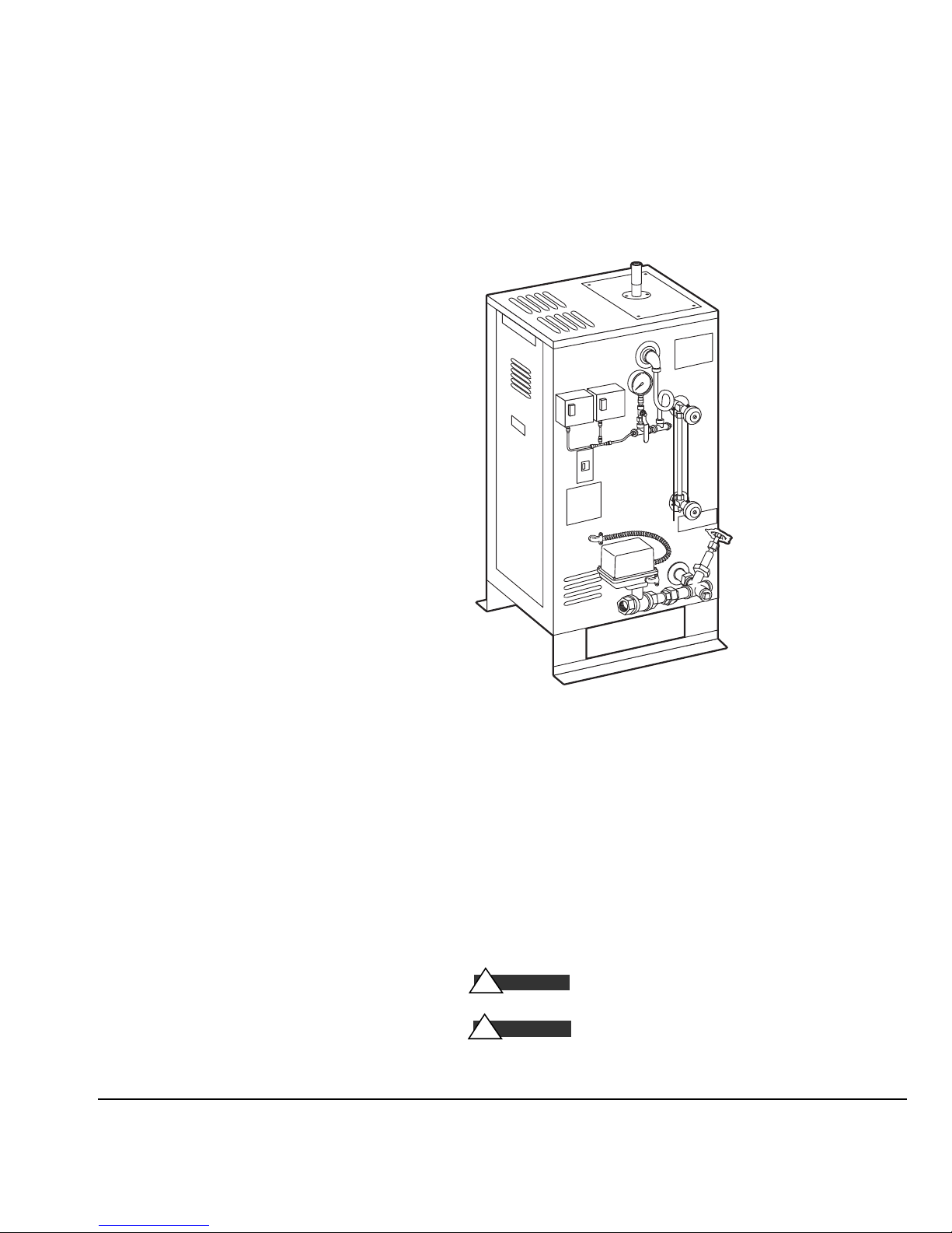
Typical CU Series Steambath Generat or
(for ill ustrative p urpos es only)
IMPORTANT NOTE:
you will notice warning and caution symbols. This information is important for the safe and efficient installation
and operation of this generator. These are types of potential hazards that may occur during this installation and
operation:
CA U T I ON
!
death if precauti ons are not fo ll owed.
WARN I N G
!
product damage may occur if y ou do not fol lo w instructio ns.
As you follow these instructions,
states a hazard may cause s erious injury or
sign als a situatio n where minor i njury or
®
steambaths
®
steam
.
mr
mr.steam
Sussman-Automatic Corp
info@mrsteam.com
www.mrsteam.com
®
43-20 34th Street
®
Long Island City, NY 11101
TEL: 800 76 STEAM
FAX: 718 472 3256
9410 S. La Cienega Blvd.
Inglewood CA 90301
TEL: 800 72 STEAM
FAX: 310 216 2944
1
PUR 100376 11/10

mr.steam
Before Installing
®
CU Series Installation, Operating & Maintenance Manual
IMPORTANT:
Although this CU Steambath Generator has been qualified for shipment by Mr. Steam, the
following must be reviewed for proper and safe use.
1.
Verify that the model and accessories are as specified and
ordered.
2.
Verify that the power voltage and control voltage at the site
is suitable for the CU Steambath Generator.
3.
Verify the correct steam generator sizing by referring to the
Mr.. Steam sizing guide. See page 5.
4.
Do NOT use black iron pipe or galvanized pipe for the
steam line. Use brass pipe or copper tubing ONLY, and
in accordance with National and local plumbing Codes.
5.
The physical size of the unit, clearance for plumbing
servicing and its distance from the steam room must all
be considered before selecting a location for the generator.
See pages 3 & 4.
Take time to read these instructions thoroughly before installing or servicing.
6.
The Manufacturer's Data Report is supplied with the generator. This is an important document and may be required by
a State or Provincial Agency. THIS DOCUMENT MUST
BE SECURED IN A SAFE LOCATION.
7.
Do not use or install unauthorized components, accessories
or products on the generator or generator piping.
IMPORTANT:
over temperature control is to be installed in accordance with
the specific instructions provided. See Note 7 below.
The Mr. Steam Digital 1 System operating and
Steam Room Guidelines
IMPORTANT:
used in conjunction with your architect, designer and contractor
in determining all factors necessary in providing a suitable and
safe steam room environment for your bathers.
IMPORTANT:
familiarize themselves with the latest edition of the American
College Sports Medicine Health/Fitness Faculty Standards and
Guidelines, or a similar resource and reference publication, and
refer to those guidelines for the proper and safe operation of a
spa facility including steam rooms.
Steam room construction information is available from the
Tile Council of America, Inc. at (864) 646-8453 or
www.tileusa.com
1.
Steam room must be completely enclosed, with full walls,
door, floor and ceiling.
2.
It is recommended that a gasketed door be used for heat sealing and steam containment. Windows, skylights and the like
that are part of the steam room should be double paned.
Only vapor sealed lighting fixtures approved for the application should be used.
CA U T I ON
!
the flooring, provide suitable anti-skid strips or equivalent,
to prevent user slipping and injury.
The following general information should be
Owners/operators should obtain a copy and
3.
If tile or other smooth surface is used for
IMPORTANT:
4.
Walls and ceilings must be constructed with water-resistant,
non-corrosive surface, such as tile, marble, molded acrylic,
or other non-porous material. The ceiling should be sloped
to prevent dripping of condensate on bathers. If acrylic,
fiberglass or other non-heat resistant- materials are used as
part of the steam room enclosure, see page 7, “Steamhead ”
and “Acrylic Shield” for important additional details.
5.
Provide floor drains for condensate run-off and steam room
cleaning.
6.
Comply with all applicable National and local building
and electrical Codes and confer with design consultants and
contractors for room construction details.
CA U T I ON
!
System is required operating equipment for each steam
room. The operating temperature control is to be set by the
owner/operator to sense desired room temperature at the
sensor location within the steam room. Connection of the
Digital 1 Over Temperature cut-off is mandatory to
provide additional protection to the bathers. The steam room
is to be operated in accordance with “Important” ºinformation as noted above.
IMPORTANT:
setting is at the discretion of the owner/operator.
7.
The Digital 1 Temperature Control
Final selection of the steam room temperature
2
mr.steam
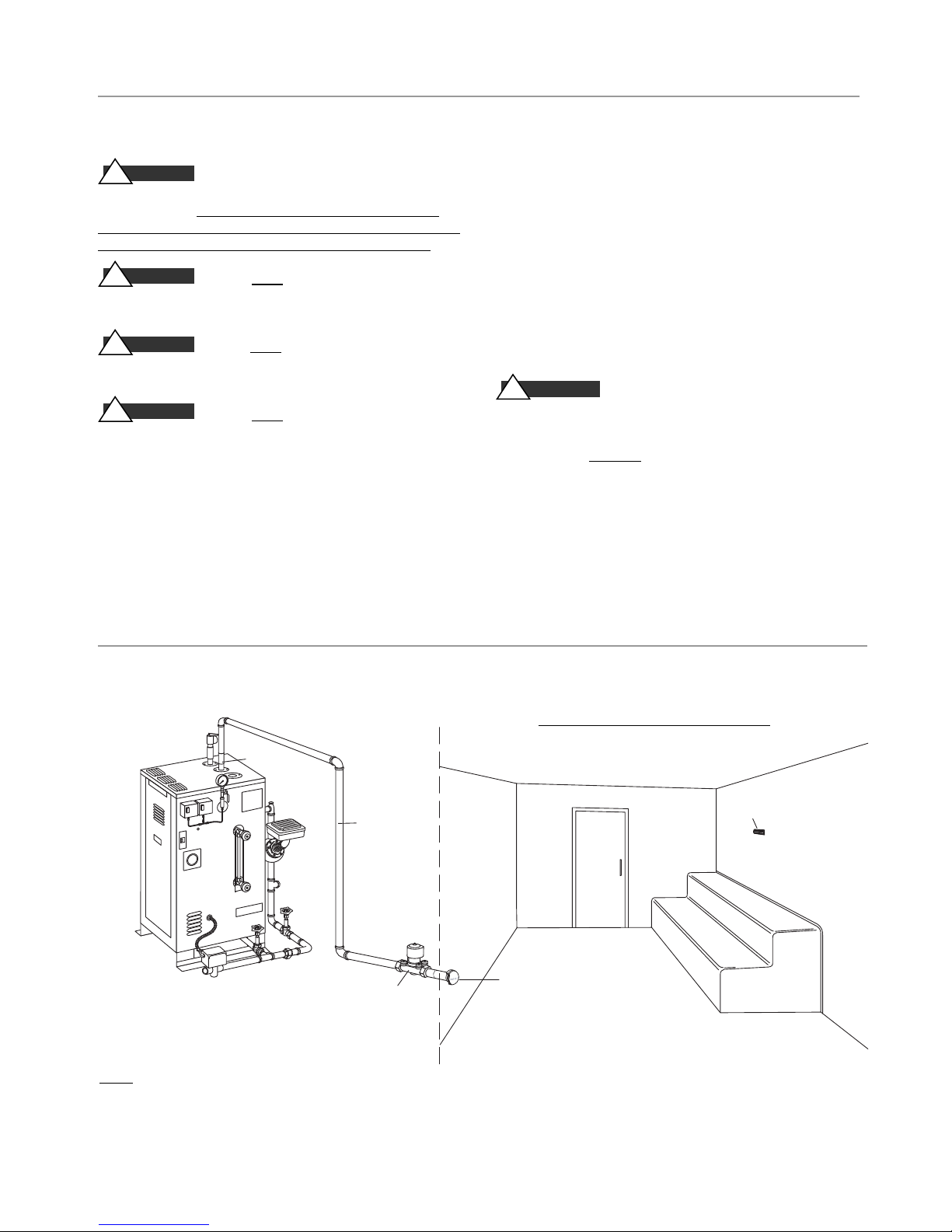
U T I L I T Y R O O M
Figure 1
3
⁄4" Steam
Solenoid
3
⁄4" Steamhead
with Acrylic Shield
Steam
Generator
Fully
Insulated
Steam Pipe
Digital 1 Sensor
1" Steam
Outlet
S T E A M R O O M
e
®
CU Series Installation, Operating & Maintenance Manual
Locating the Steam Generator Unit
CA U T I ON
!
generators are designed to NEMA Type 1 requirements and
are intended for indoor use only. They are to be located
indoors in a dry, clean location and are not to be subjected
to moisture, condensate, hose wash down or the like.
CA U T I ON
!
outdoors or wherever environmental conditions may effect
the safety and/or performance of the generator.
CA U T I ON
!
locations such as unheated attics or basements, or where
water could freeze.
CA U T I ON
!
near flammable or corrosive materials, or chemicals such as
gasoline, paint thinners, or the like. Installation in areas
having high concentrations of chlorine (such as pool equipment room) must be avoided.
5. IMPORTANT: Select a location for steam generator in
accordance with items 1-4 above and within 25 feet of
the steam room. Reference “Dimensional & Clearance
Specifications” information on page 4. See page 5 for
guidance if generator is more than 25 feet from steam
room.
1. Mr.Steam®CU commercial steambath
2. Do NOT install steambath generator
3. Do NOT
4. Do NOT
install steambath generator in
install steambath generator
. Install steambath generator on a solid and level surface,
6
and mechanically secure generator in place.
7. Provide access to the steambath generator for servicing.
See page 4 for Dimensional & Clearance Specifications
8. IMPORTANT: Steam line, safety valve and drain valve and
plumbing, and steamheads become hot during operation
and remain hot after shutdown for a period of time.
Provide appropriate protection, including insulating
plumbing lines. Avoid plumbing runs and steam head
locations that can come in contact with service personnel
and bathers. See page 6.
WARN I N G
!
from the bather seating areas and traffic patterns.
IMPORTANT: A LOCKED UTILITY ROOM THAT ONLY PERMITS
ACCESS TO THE STEAM GENERATOR AND ITS CONTROLS BY
AUTHORIZED PERSONNEL AND IS NOT ACCESSIBLE TO THE
GENERAL PUBLIC IS STRONGLY RECOMMENDED.
9. Each steamhead must be located away
Mr. Steam Installation
NOTE: FOR ILLUSTRATIVE PURPOSES ONLY. Optional equipment shown.Consult with qualified designer, architect
or contractor for steam room construction details, including location of steam head(s) and sensors.
3
For Illustrative Purposes Only
mr.steam
®
CU Series Installation, Operating & Maintenance Manual
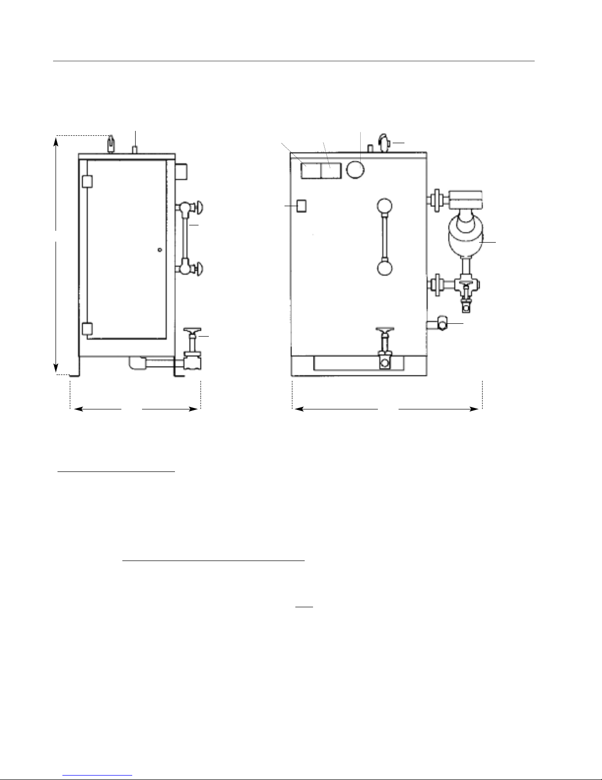
Dimensions & Clearance Specifications
Height
Steam Outlet
Operating
Pressure
A
Gauge Glass
Assembly
Control
On/Off
Switch
High Limit
Pressure
Control
D
E
L
Pressure
Gauge
15 PSIG
Safety Valve
MM 150 Liquid
Level Control
E
R
(see note 2)
B
Water Feed Inlet
Drain Valve
FrontLeft
Width Length
F
Figure 2:
Typical Arrangement of Boiler with McDonnell Miller.
For illustration purposes only.
Refer to all notes below
NOTES for Figure 2:
1.
All dimensions are approximate. Refer to chart on Page 5.
2
. MM150 Liquid Level Control on CU-2000 and larger models only.
CU-360 to CU-1400 have electronic liquid level controls.
3. IMPORTANT
: Minimum clearance from combustible surfaces.
Refer to Fig. 2 above for legend.
A
1" above top of CU generator
B
Front of CU generator suitable for alcove installation only.
D
1" from rear of CU generator.
E
1" from left side of CU generator.
L
E
16" from right side of CU generator.
R
F
Type of flooring: “C", suitable for combustible flooring.
4.
For ease of servicing, Mr. Steam recommends a minimum of
36 inches of clearance all around the CU generator.
4

mr.steam
®
CU Series Installation, Operating & Maintenance Manual
Select a Mr. Steam®CU Series Generator
The resultant calculated volume of the steam room determines
the Model CU steambath generator required. Steam room size
and additional constructional factors affect model selected.
A.
To determine the steam room volume first multiply
Length x Width x Height of the steam room
__________________________________________________
Example: A steam room 8' x 9' x 8' = 576 Cu. Ft.(volume).
Select the Mr. Steam Model which is the next larger volume.
In this example, Model CU-750 is the correct selection.
Example: 2 Steam rooms each 6' x 10' x 7' x 2 rooms = 840
Cu. Ft. (volume).
In this example, Model CU-1000 is the correct selection.
SEE NOTE B BELOW
NOTE:
Insure adequate consideration is given to assure that the
CU unit selected is not undersized for the room.
B. NOTE:
the steambath generator:
1.
2
. Piping runs longer than 25 feet from the steambath genera-
3
. Exterior walls and outside windows: Increase volume.
Certain additional factors effect the correct sizing of
Construction materials such as glass or glass block, natural
marble or other stones: Increase volume.
tor to the steam room: Increase volume.
4
. Steam room with interior height in excess of 8 feet:
Increase volume
C. IMPORTANT:
recommendations only. Always
designer or architect. For general information, contact East
Coast: 1-800-767-8326 or West Coast: 1-800-727-8326.
D. IMPORTANT:
Steambath generator the following is strongly recommended for best performance and user satisfaction.
1
. One CU steambath generator should service no more that
two (2) steam rooms, each relatively similar in size and
construction.
2.
If two (2) steam rooms are serviced by one (1) CU generator, the combined resultant room volume of the two rooms
should not exceed 1000 cubic feet.
3.
Each room must be operated with the appropriate Digital 1
temperature control system inclusive of the room operating
temperature control and the high-limit temperature control.
4.
In any case, the purchase and/or owner/operator must consult with a designer, architect, and/or consultant to assure
the proper specification of the steam generator.
The above selection guidelines are
consult with contractor,
When specifying a CU Commercial
Model No. KW Room Volume (cu ft) Size NPT Outlet Size, NPT Width Length Height Wt. lbs.
CU-360 9 400 3/8" 1" 20 30 38 250
_____________________________________________________________________________________________________
CU-500 12 500 3/8" 1" 20 30 38 250
_____________________________________________________________________________________________________
CU-750 18 750 3/8" 1" 20 30 38 250
_____________________________________________________________________________________________________
CU-1000 24 1000 3/8" 1" 20 30 38 270
_____________________________________________________________________________________________________
CU-1250 30 1250 3/8" 1" 20 30 38 290
_____________________________________________________________________________________________________
CU-1400 36 1400 3/8" 1" 20 30 38 300
_____________________________________________________________________________________________________
CU-2000 48 2000 1/2" 1" 24 33 44 330
_____________________________________________________________________________________________________
CU-2500 60 2500 1/2" 1" 24 33 44 380
_____________________________________________________________________________________________________
CU-3000 72 3000 1/2" 1" 24 33 44 390
_____________________________________________________________________________________________________
CU-4500 108 4500 1/2" 1-1/2" 28 34 59 625
_____________________________________________________________________________________________________
*After taking into consideration all factors affecting resultant steam room volume, including materials of construction, distance
from generator to steam room, interior height of steam room ceiling, outside/exterior walls and windows etc, select proper
Model CU generator. Consult with an architect, engineer, designer and/or contractor before making final selection
Maximum* Water Inlet Steam Generator Dimensions (inches) Shipping
.
5
mr.steam
Installation
®
CU Series Installation, Operating & Maintenance Manual
Plumbing
All plumbing shall be performed by a qualified
licensed plumber and in accordance with applicable
National and local Codes.
Water Supply
1.
Connect to hot or cold water line. A hot water line
is preferable, however incoming hot water should
not exceed 160°F
IMPORTANT:
hot water heaters provides 120°F water
2.
Provide a service shut off valve and water-line
strainer in the water supply line upstream to the
steambath generator
3.
Flush the inlet water line thoroughly before making connection to the steambath generator.
4.
Incoming water supply should be at least 25 psig
and is not to exceed 100 psig.
5.
Install a back flow preventor as required by Code.
6.
Provide anti-water hammer device as required in
accordance with Code.
7.
Use of unions in plumbing lines is strongly
recommended.
8.
Recheck all factory and field plumbing connections for tightness.
The low temperature setting on many
Steam Line
1.
The Digital 1 steam solenoid valve should be plumbed as close as
practical to the steam room using only brass pipe or copper tubing
but should remain accessible for service.
2.
Pitch the steam line a minimum of 1/4”per linear foot of run,
towards the steam outlet on the generator, avoid valleys and trapping of condensate.
3.
Fully insulate steam lines with suitably-rated high temperature
insulation.
4.
Install a suitable strainer or filter between the steam generator and
steam solenoid valve.
5.
Use of unions in plumbing lines is recommended.
Drain
In accordance with Code requirements, provide a drain line
connection from the steambath generator drain valve(s). If an Auto
Blowdown is used, the drain line must be connected to
the automatic blowdown valve. Refer to National and local plumbing
Codes for drain requirements including receptor,
trap, vent requirements and drain lines.
Safety Valve
Where permitted by Code, provide a
connection for safety |valve discharge.
P I P E SI Z E GU I D E
_____________________
Steam Outlet: 1"
Steam Solenoid Valve:3/4"
Steam Head: 3/4"
WARN I N G
!
DO NOT
DO NOT
connect a shut off valve or plug at the safety valve outlet.
reduce outlet size of safety valve discharge.
Water Quality Information
For optimum results, the feedwater supply should be
tested prior to initial startup. If the mineral content
exceeds the following recommended limits, various
external treatment processes may be used to correct the
problem.
NOTE:
An analysis of the on-site boiler feedwater must
be made by a recognized and reliable water treatment
company to ascertain the existing condition and treatment required.
Recommended Feedwater Quality
Hardness, ppm 8 – 85 (~0.5 – 5 gpg)
P-Alkalinity, ppm 85 – 410 (~5 – 24 gpg)
T. Alkalinity, ppm 200 – 500 (~7 – 0 gpg)
pH (strength of alkalinity) 8.0 – 11.4
Blowdown boiler at least a once a day. If boiler water
or feed-water are outside the above limits, a more
frequent blowdown is required
Recommended Limits Within a Boiler
Total Dissolved Solids, ppm 3500 Sulfite (SO3), ppm 25 – 50
Total Alkalinity, ppm 850 Phosphate, ppm 30 – 60
Suspended solids, ppm 300 P-Alkalinity as CaCO3, ppm 900
Silica (SiO2), ppm 125 Iron, ppm 2
Water quality can affect efficiency or result in boiler damage if neglected. Boiler feedwater contains impurities in solution and suspension.
These impurities concentrate in the boiler. The concentration of these
impurities increases as more feedwater is introduced into the boiler and
steam is produced. If the suspended solids are allowed to concentrate
beyond certain limits, a deposit or “scale” will form on the boiler
internal surfaces. This deposit can interfere with the proper boiler
operation and cause boiler failure.
The concentration of these impurities is generally controlled by the
feedwater quality and by blowdown. Blowdown refers to removing a
portion of the boiler water with high solids concentration and replacing it with makeup water of a lower concentration.
6
mr.steam
Fully Assembled
Assembly
Steam Head
Steam Pipe
Acrylic Sheild
®
CU Series Installation, Operating & Maintenance Manual
Steam Room Guidelines
IMPORTANT:
and contractor in determining all factors necessary in providing a suitable and safe steam room environment
for your bathers.
IMPORTANT:
American College of Sports Medicine Health/Fitness Faculty Standards and Guidelines (ISBN: 0736051538),
or a similar resource and reference publication, and refer to those guidelines for the proper and safe operation
of a spa facility including steam rooms.
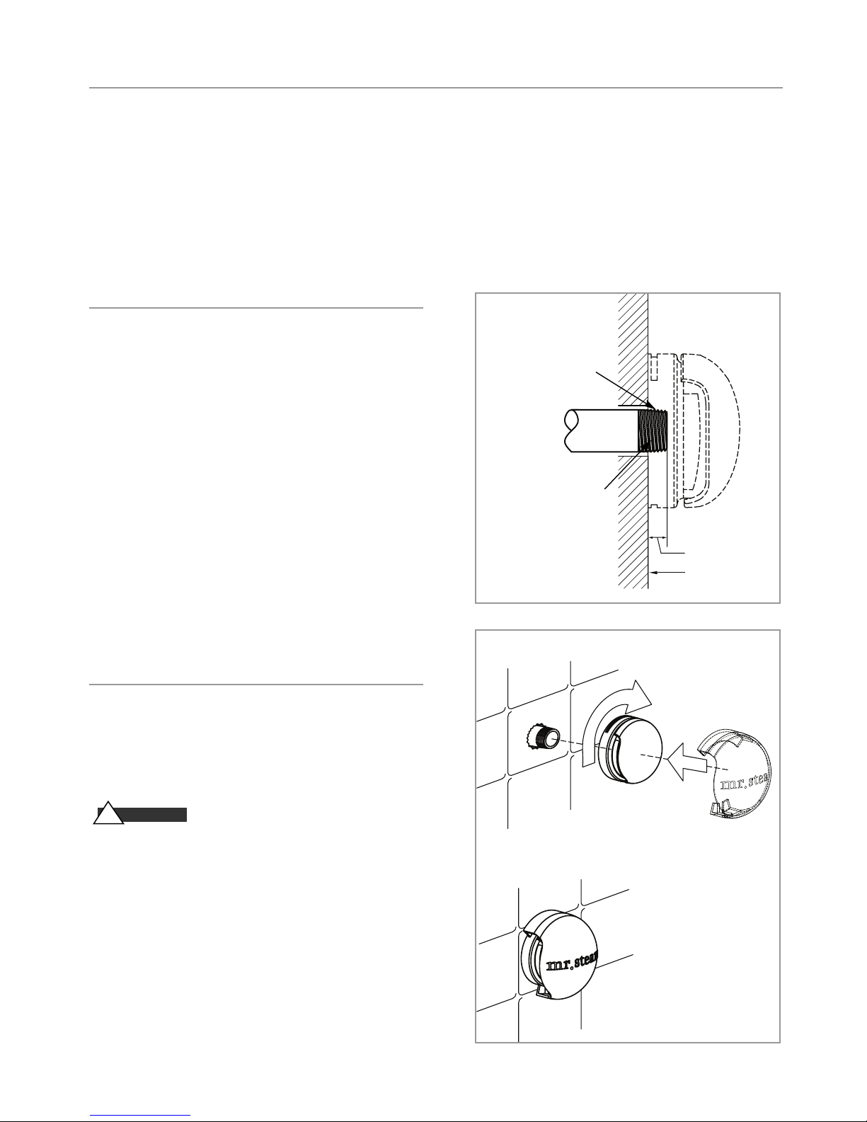
Steamhead
1
. For steam rooms constructed of tile, marble or similar non-
porous heat-resistant materials for the enclosure, locate
steam head 12 inches above steam room floor and install
Mr. Steam PN CU-103985 acrylic shield on each steamhead.
IMPORTANT:
other non-heat resistant materials used for steam room enclosure, install each steam head 20-30 inches above the floor.
2.
Locate each steamhead away from bather seating area and
away from traffic patterns.
3.
Install each steamhead with steam slots facing to the left
and right as shown in the diagrams.
4. NOTE:
or other tools to tighten. Use of proper thread sealant and
hand tightening is usually sufficient.
5.
Apply a bead of silicone around the steamhead where it
meets the wall.
The following general information should be used in conjunction with your architect, designer
Owners/operators should obtain a copy and familiarize themselves with the latest edition of the
(3/4” N.P.T.)
Use Teflon or equal
sealant on pi pe t hreads
Steam
For Steam rooms using acrylic, fiberglass or
To preserve the steamhead finish, do not use wrench
Fill g ap with sili cone or
equal sealan t as required
Diagram A
Supply P ipe
for mois ture seal
Steam Head
3/4”
Finis hed in terior face
of steam ro om wall
Acrylic Shield
Apply a small bead of silicone in the grooves on the top and
bottom of the steamhead. Place an Acrylic Shield (PN 103985)
over the steamhead until the tabs engage the grooves in the
steamhead.
WARN I N G
!
acrylic shield may expose users or surfaces to hot steam. Do
not operate steam room without an acrylic shield on each
steamhead.
IMPORTANT:
containing emulsifiers or aldehydes. Acrylic Shield damage may result.
Mr. Steam oils are approved for use with this acrylic shield.
Operation of the steam room without an
Do not use with water soluble fragrance or fragrance
Diagram B
7

mr.steam
®
CU Series Installation, Operating & Maintenance Manual
Electric
WARN I N G
!
switch before proceeding. All electrical wiring must be installed by a qualified licensed electrician
in accordance with National and local Codes.
The steambath generator is factory wired and pre-tested before shipment. Electrical power supply
details are provided on the data plate secured to the generator and as part of this manual. Refer to
applicable wiring and schematic information.
1.
Check power and control circuit voltage requirements on the data plate.
NOTE:
Separate 120 VAC line is not required if optional 120 VAC control transformer has been
purchased and provided as factory equipment.
2.
Use minimum 90° C insulated copper conductors only for field wiring, sized in accordance
with National and local electric Codes. Refer to Amperage Chart below.
3.
Connect suitably sized copper equipment grounding conductor in accordance with National and
local electric Codes to ground terminal provided.
4.
Install a separate dedicated circuit breaker or other approved overcurrent protection device
between the incoming electrical supply and the generator, in accordance with National and local
electric Codes.
5. IMPORTANT:
tighten all electrical connections including all factory connections at the terminal block, fuse
block, top and bottom of contactor and element pins prior to energizing generator (torque
values are listed on individual components, control circuit terminal strips should be torqued
to 20 in-lbs.).
Electric shock hazard. Disconnect all power supplies at the main disconnect
With main disconnect switch off and no electric power entering the generator,
AMPERAGE CHART - Indicates Total Ampere Draw of Specific CU Model at Voltage & Phase Specifie
Model No. kW 208V/1 PH 208V/3 PH 240V/1 PH 240V/3 PH 480V/3 PH 600V/3
PH
________________________________________________________________________________________
CU-360 9 44 25 38 22 11 9
________________________________________________________________________________________
CU-500 12 58 34 50 29 15 12
________________________________________________________________________________________
CU-750 18 87 50 75 44 22 18
________________________________________________________________________________________
CU-1000 24 116 67 100 58 29 24
________________________________________________________________________________________
CU-1250 30 145 84 125 73 37 29
________________________________________________________________________________________
CU-1400 36 - 100 - 87 44 35
________________________________________________________________________________________
CU-2000 48 - 134 - 116 58 47
________________________________________________________________________________________
CU-2500 60 - 167 - 145 73 58
________________________________________________________________________________________
CU-3000 72 - 200 - 174 87 70
________________________________________________________________________________________
CU-4500 108 - 300 - 260 130 104
________________________________________________________________________________________
IMPORTANT: Use minimum 90° C insulated copper conductors only for field wiring sized in accordance with
National and local electric Codes.
NOTE:
Consult factory for other voltage/phase combinations. CU generators are suitable for 50/60 hz. Standard
control circuit voltage for above V/PH combinations for United States, Canada and Mexico is 120 VAC.
Exception: 220-240 VAC control circuit voltage is provided on non-domestic product where power voltage is 220240 V/3 PH, 380V/3PH, 415V/3 PH, etc.
d
8

mr.steam
®
CU Series Installation, Operating & Maintenance Manual
Wiring
CA U T I ON
!
steambath generator shall be suitably grounded in accordance with National Electric and local Codes. Disconnect all
power supplies at the main disconnect switch before proceeding.
1.
Electric wiring to the steambath generator must be in
accordance with National Electrical and local wiring
Codes following wiring diagram supplied. Such wiring
shall be done by a licensed electrician. See Amperage
Chart and Notes, Page 8.
2.
The unit is wired and pre-tested before shipment. Follow
all instructions provided for safely and properly wiring
steambath generator and accessories.
CA U T I ON
!
quate capacity employing suitably rated circuit breakers or
fuses between main electrical power source(s) and the generator. Location of safety switch to be in accordance with
National and local electric codes.
To avoid possible electric shock, the
Installer shall use a safety switch of ade-
. IMPORTANT:Insure all electrical connections are sufficiently
3
tightened prior to energizing generator.
See Page 8, Item 5.
WARN I N G
!
of wiring systems voids warranty and can lead to dangerous
operating conditions.
4.
The Digital 1 Temperature Sensor and High Limit
Temperature sensor(s) must be located inside the steam room.
Locate approximately 5 feet above the steam room floor,
preferably away from steam heads.
5.
The Digital 1 steam solenoid valve(s) shall be located outside
the steam room and shall be wired to the Digital 1 controller(s) in accordance with wiring diagram provided. See
applicable wiring diagrams included as part of this manual.
CA U T I ON
!
securely crimped soldered and sealed with heat shrink tubing.
Substitution of components or modification
Ensure all splices in the sensor cable are
Typical Power Wiring Diagram
__ __ __ __
__________
IMPORTANT:
Field Wiring
Factory Wiring
3PH Power Supply
Diagram #1
Units with 1 Contactor (see note 1)
Also refer to Control Circuit diagrams in this manual.
GRD
Power Contactor
Heating Element
3PH Power Supply
GRD
Power Terminal Block
Power Contactors
Heating Elements
Diagram #2
Units with 2 or more Contactors (see note 1)
9

mr.steam
®
CU Series Installation, Operating & Maintenance Manual
Control Circuit Wiring Diagram
SEE PAGES 11, 12 & 13 FOR DIAGRAMS
CA U T I ON
!
Installer shall use a safety switch of adequate capacity employing suitably rated circuit breakers or fuses between main electrical power
source(s) and the generator. Location of safety switch to be in accordance with National and local electrical codes.
NOTES:
1.
Larger rooms may require two or more steam solenoid valves in
parallel.
2.
When generator services two rooms, second room requires a set of
Digital 1 and solenoid valves.
IMPORTANT:
Digital 1 Plus sensors are intended to be field installed within the
3.
steam room at the location selected by the designer/architect. DO
NOT LOCATE THE DIGITAL 1 SENSOR NEAR OR ABOVE
THE STEAMHEAD(S) AS THIS MAY CAUSE DIRECT
STEAM EMISSION TO INTERFERE WITH STEAMROOM
TEMPERATURE REGULATION.
4.
Autoflush System 24 hr. timer and Digital 1 operating settings are
at the discretion of the owner/operator.
IMPORTANT:
themselves with the latest edition of the American College of Sports
Medicine Health/Fitness Faculty Standards and Guidelines, or a similar resource and reference publication, and refer to those guide lines
for the proper and safe operation of a spa facility including steam
rooms. Steam room construction information is avail-able from the
Tile Council of America, Inc. at (864) 646-8453 or www.tileusa.com.
WARN I N G
!
required
perature control is to be set by the owner/operator to sense desired
room temperature at the sensor location within the steam room.
Connection of the Over Temperature portion of the Digital 1 control
is mandatory to provide additional protection to the bathers. The
steam room is to be operated in accordance with “Important” information as noted above.
IMPORTANT:
is at the discretion of the owner/operator.
WARN I N G
!
securely crimped soldered and sealed with heat shrink tubing.
Owners/operators should obtain a copy and familiarize
The Digital 1 Temperature Control System is
operating equipment for each steam room. The operating tem-
Final selection of the steam room temperature setting
Ensure all splices in the sensor cable are
10
 Loading...