

Page 1
IMPORTANT CONSUM ER SAFETY IN FORMATION
WARNING: R IDING A BIKE IS DANG EROUS. NOT PROPERLY MAINTAINING OR
INSPECTING YOUR BIKE AND ITS COMPONENTS IS EVEN MORE DANGE ROUS. IT IS
ALSO DANGEROUS TO NOT READ AND FOLLOW THESE INSTRUCTIONS.
1. DO NOT PERFO RM ANY MODI FICATIONS OR ADJUSTMENTS THAT ARE NOT OUTLINED IN THIS
MANUAL.
2. INSPECT YOUR C HAIN GUI DE BEFO RE EVERY RI DE. INSPECT AR EAS FOR ANY SIGNS OF
EXCESSIVE RU BBI NG, BEN DING, CRACK ING OR OTHER DAMAGE. I F YOU NOTICE ANYTHING
ABNOR MAL, DO NOT RIDE IT. RETUR N IT TO YOUR DEALER OR CONTACT MRP FOR A COMPLETE
INSPECTIO N AND NECESSARY R EPAIR.
3. MRP R ECOMME NDS THAT YOU WEAR PROPER SAFETY EQU IPME NT EVERY TIME YOU R IDE,
INCLUDI NG APPROVED B ICYCLE HELMET. NEVER RI DE AT NIGHT WITHOUT LIGHTS.
4. ALWAYS USE GENU INE MR P PARTS. USE OF AFTER MARKET RE PLACEME NT PARTS AND
UPGRAD ES VOIDS THE WARRANTY AN D COULD CAUSE STRUCTURAL FAILURE.
MRP H IGHLY RECOMME NDS THAT YOU HAVE YOUR NEW GUIDE INSTALLED BY A PROFESSIONAL
MECHANIC AT YOUR FAVORITE LOCAL BIKE SHOP. IF YOU HAVE ANY DOUBTS ABOUT HOW TO
INSTALL YOUR GU IDE, TAKE IT TO A BIKE SHOP. YOU’LL BE GLAD YOU DID.
COMPATIBI LITY
The D-Mount 1x guide is
compatible with most singlering specific and three-ring
cranks (with outer and inner ring
removed) and can accommodate
a 49-51mm chainline on standard
mountain bikes and 62.5-64.5mm
chainline on most “fat” bikes.
Used in a single-ring application,
two-ring “double” cranks may
produce a wide chainline
incompatible with the D-Mount
1x. There are several “offset”
chainrings on the market that can
fix this incompatibility.
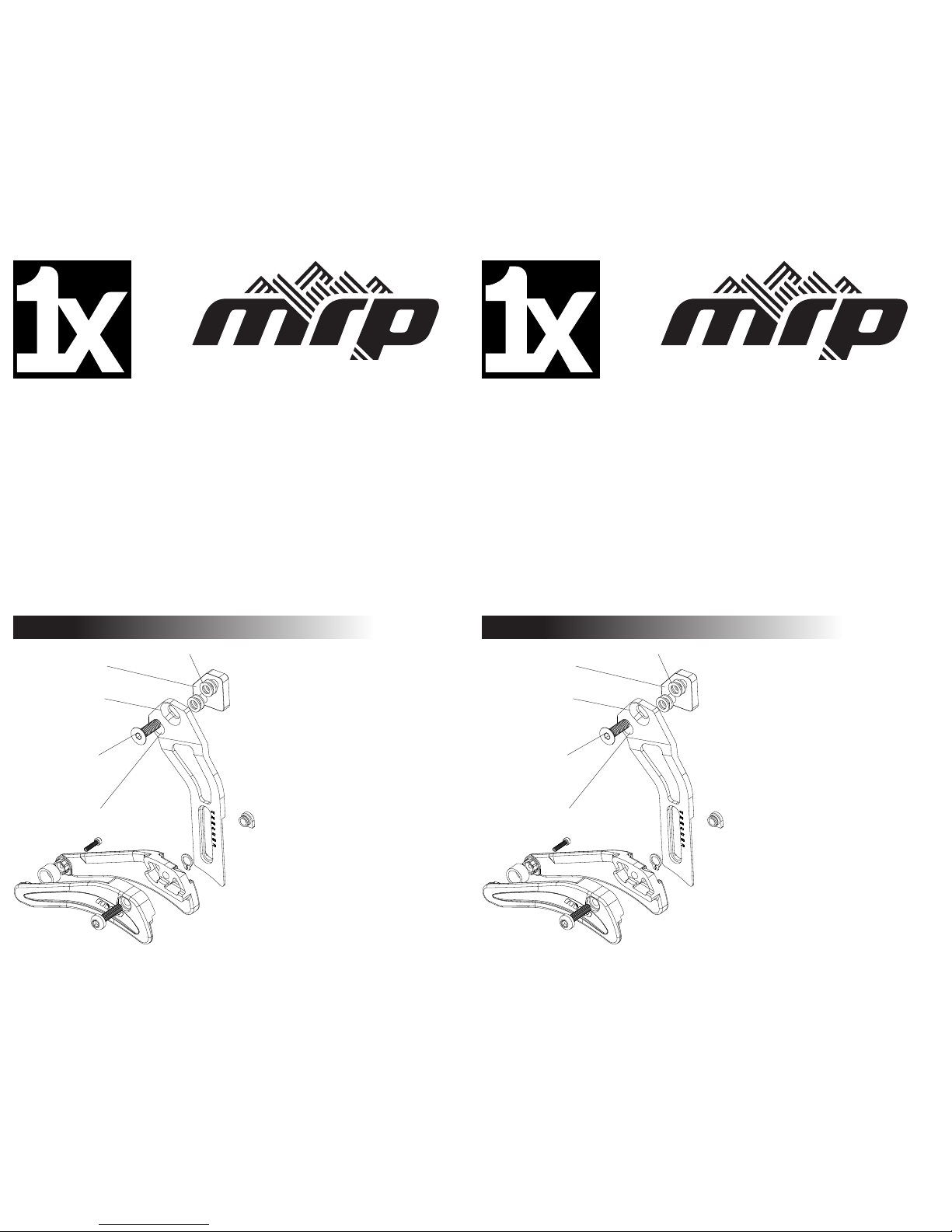
The D-Mount 1x guide includes
four 1mm spacers that can be
installed on the mounting bolt and
pivot boss between the mounting
plate and guide arm.
1
USE R MANUAL
D-MOUNT MODEL
MOUNTI NG
PLATE
GUIDE
ARM
PIVOT
BOSS
MOUNTI NG
B O LT
SPACER
IMPORTANT CONSUM ER SAFETY IN FORMATION
WARNING: R IDING A BIKE IS DANG EROUS. NOT PROPERLY MAINTAINING OR
INSPECTING YOUR BIKE AND ITS COMPONENTS IS EVEN MORE DANGE ROUS. IT IS
ALSO DANGEROUS TO NOT READ AND FOLLOW THESE INSTRUCTIONS.
1. DO NOT PERFO RM ANY MODI FICATIONS OR ADJUSTMENTS THAT ARE NOT OUTLINED IN THIS
MANUAL.
2. INSPECT YOUR C HAIN GUI DE BEFO RE EVERY RI DE. INSPECT AR EAS FOR ANY SIGNS OF
EXCESSIVE RU BBI NG, BEN DING, CRACK ING OR OTHER DAMAGE. I F YOU NOTICE ANYTHING
ABNOR MAL, DO NOT RIDE IT. RETUR N IT TO YOUR DEALER OR CONTACT MRP FOR A COMPLETE
INSPECTIO N AND NECESSARY R EPAIR.
3. MRP R ECOMME NDS THAT YOU WEAR PROPER SAFETY EQU IPME NT EVERY TIME YOU R IDE,
INCLUDI NG APPROVED B ICYCLE HELMET. NEVER RI DE AT NIGHT WITHOUT LIGHTS.
4. ALWAYS USE GENU INE MR P PARTS. USE OF AFTER MARKET RE PLACEME NT PARTS AND
UPGRAD ES VOIDS THE WARRANTY AN D COULD CAUSE STRUCTURAL FAILURE.
MRP H IGHLY RECOMME NDS THAT YOU HAVE YOUR NEW GUIDE INSTALLED BY A PROFESSIONAL
MECHANIC AT YOUR FAVORITE LOCAL BIKE SHOP. IF YOU HAVE ANY DOUBTS ABOUT HOW TO
INSTALL YOUR GU IDE, TAKE IT TO A BIKE SHOP. YOU’LL BE GLAD YOU DID.
COMPATIBI LITY
The D-Mount 1x guide is
compatible with most singlering specific and three-ring
cranks (with outer and inner ring
removed) and can accommodate
a 49-51mm chainline on standard
mountain bikes and 62.5-64.5mm
chainline on most “fat” bikes.
Used in a single-ring application,
two-ring “double” cranks may
produce a wide chainline
incompatible with the D-Mount
1x. There are several “offset”
chainrings on the market that can
fix this incompatibility.
The D-Mount 1x guide includes
four 1mm spacers that can be
installed on the mounting bolt and
pivot boss between the mounting
plate and guide arm.
1
USE R MANUAL
D-MOUNT MODEL
MOUNTI NG
PLATE
GUIDE
ARM
PIVOT
BOSS
MOUNTI NG
B O LT
SPACER
Page 2
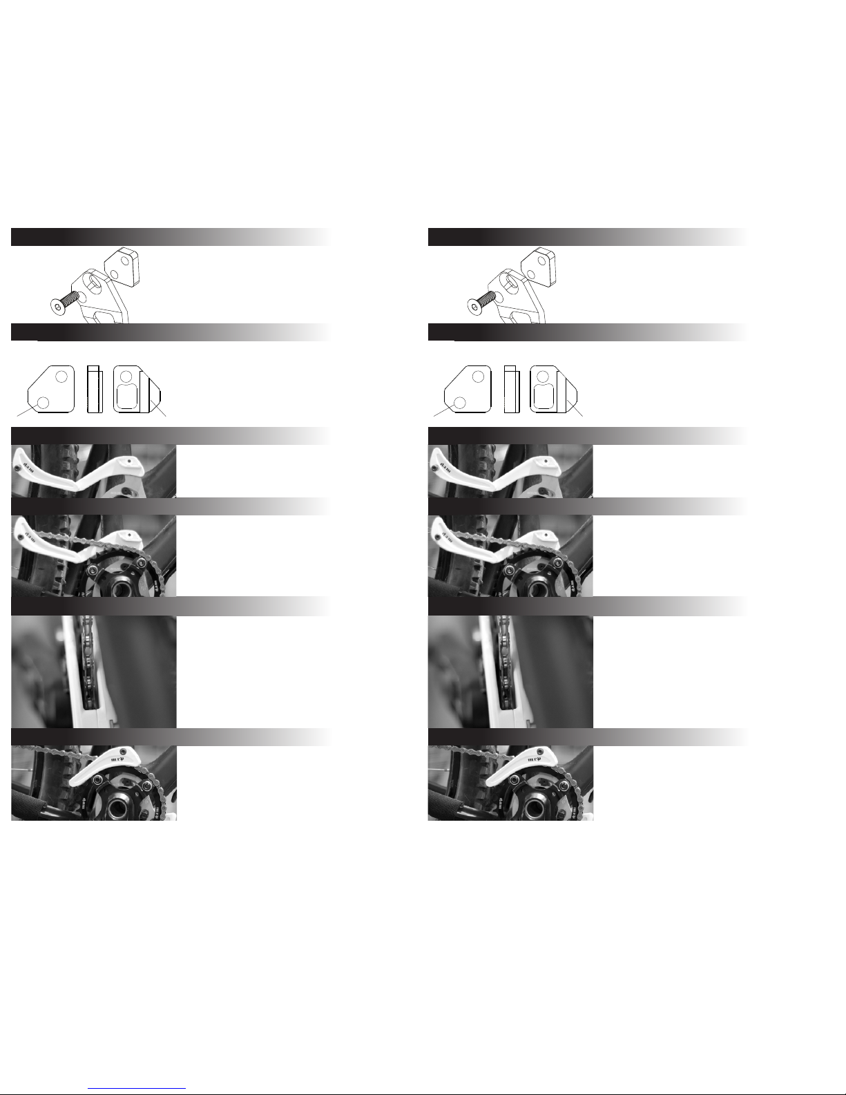
Install the crankset and chain. Close the upper
guide and reinstall the upper guide bolt. Tighten
the upper guide bolt to 1.2-1.3 Nm. The backplate
features laser etching to assist in the vertical
positioning of the guide. There should be roughly
3mm of space between the chain and the ceiling of
the upper guide.
Unthread the upper guide bolt from the captive
slider nut, pull it halfway through the upper guide,
and swing the upper guide open.
Check that all fasteners have been appropriately
tightened and that there is no unwanted rubbing
or contact anywhere in the assembly. Check
the functionality of the of the guide in a safe
environment.
Check that the alignment of the guide is correct. The
chain should be centered in the upper guide in the
middle range of the cassette. There should be little
or no contact between the chain and upper guide
while in the smallest or largest cogs of the cassette.
Refine this spacing using the included 1mm spacers
if necessary.*
*This will require reversal of the installation steps
thus far and restarting at step one.
2
Bring the mounting plate and guide arm together,
insert the mounting bolt through the kidney shaped
track on the upper portion of the guide arm. The
kidney shaped track allows for angular adjustment of
the guide.
4
5
6
7
FOR MORE INFORMATION PLEASE VISIT US ON THE WEB AT
MRPBIKE.COM
OR CALL US AT (970)241-3518, WE’LL BE GLAD TO ASSIST YOU!
Locate the front derailleur mount on your frame and
align the tongue and groove interface between it and
the mounting plate. Thread the mounting bolt into the
frame and tighten to 5-6 Nm.
3
PIVOT BOSS TONGUE
FRONT
SIDE REAR
MOUNTING BRACKET
Install the crankset and chain. Close the upper
guide and reinstall the upper guide bolt. Tighten
the upper guide bolt to 1.2-1.3 Nm. The backplate
features laser etching to assist in the vertical
positioning of the guide. There should be roughly
3mm of space between the chain and the ceiling of
the upper guide.
Unthread the upper guide bolt from the captive
slider nut, pull it halfway through the upper guide,
and swing the upper guide open.
Check that all fasteners have been appropriately
tightened and that there is no unwanted rubbing
or contact anywhere in the assembly. Check
the functionality of the of the guide in a safe
environment.
Check that the alignment of the guide is correct. The
chain should be centered in the upper guide in the
middle range of the cassette. There should be little
or no contact between the chain and upper guide
while in the smallest or largest cogs of the cassette.
Refine this spacing using the included 1mm spacers
if necessary.*
*This will require reversal of the installation steps
thus far and restarting at step one.
2
Bring the mounting plate and guide arm together,
insert the mounting bolt through the kidney shaped
track on the upper portion of the guide arm. The
kidney shaped track allows for angular adjustment of
the guide.
4
5
6
7
FOR MORE INFORMATION PLEASE VISIT US ON THE WEB AT
MRPBIKE.COM
OR CALL US AT (970)241-3518, WE’LL BE GLAD TO ASSIST YOU!
Locate the front derailleur mount on your frame and
align the tongue and groove interface between it and
the mounting plate. Thread the mounting bolt into the
frame and tighten to 5-6 Nm.
3
PIVOT BOSS TONGUE
FRONT
SIDE REAR
MOUNTING BRACKET
 Loading...