

Page 1
LEADERS IN CAMERA ROBOTICS
CRANES AND RIGS | BROADCAST | HEADS & DSLR | PRODUCT PHOTOGRAPHY | RENTALS
Titan
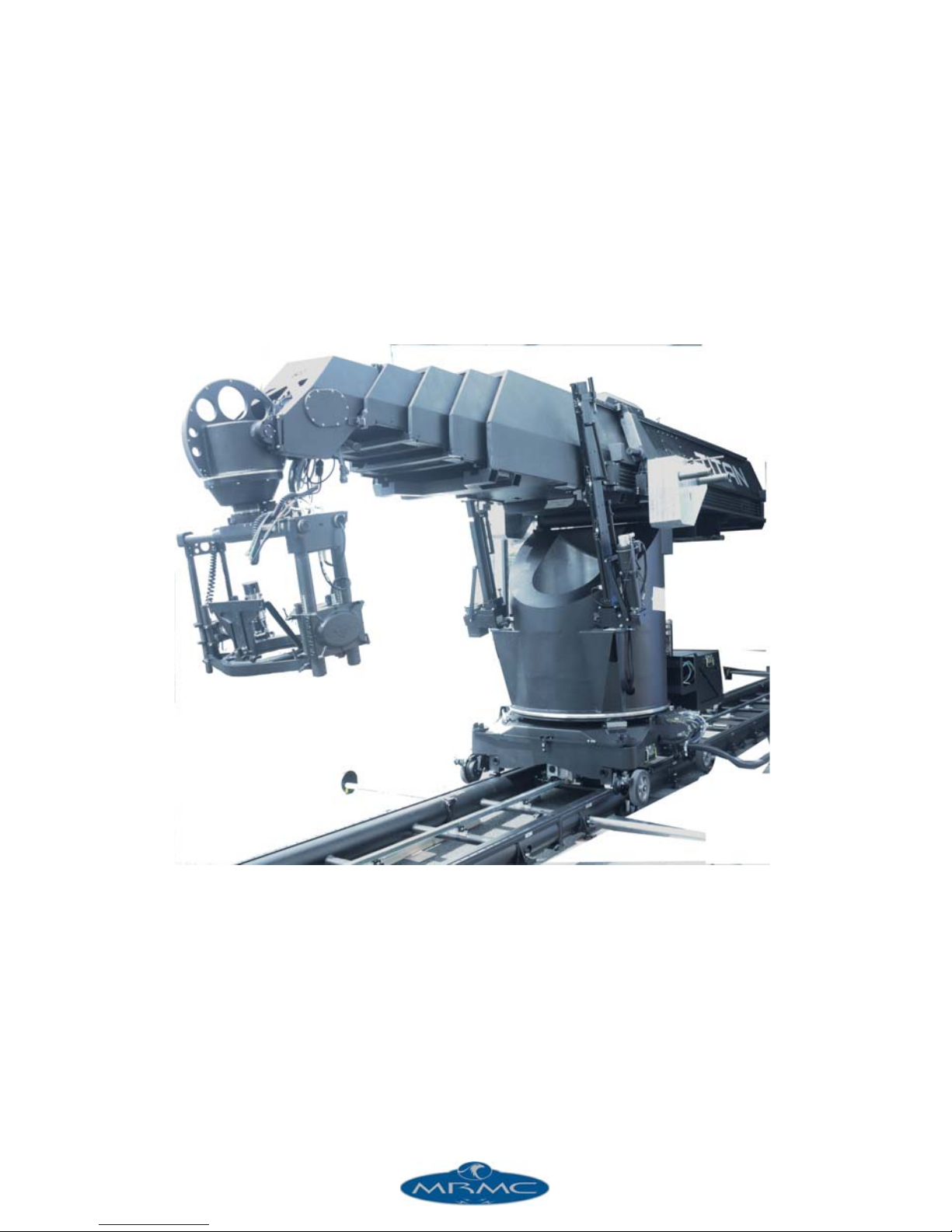
WORLD’S LARGEST TELESCOPIC MOTION CONTROL ARM
Quick Start Guide
Product code: MRMC-1479-00
Part number: MRMC-1489-00
Page 2

ii
Titan Quick Start Guide
Product code: MRMC-1479-00
Part number: MRMC-1489-00
© 2016 Mark Roberts Motion Control Ltd. All rights reserved.
No part of this publication may be reproduced, transmitted, or translated
by any means — graphical, electronic, or mechanical — including
photocopying, recording, taping, or storage in an information retrieval
system, without the express written permission of Mark Roberts Motion
Control.
Although every care has been taken to ensure that the information in this
document is accurate and up to date, Mark Roberts Motion Control
continuously strives to improve their products and may make changes to
the hardware, firmware, and software described in this document. Mark
Roberts Motion Control therefore cannot be held responsible for any
error or omission in this document.
All product names mentioned herein are the trademarks or registered
trademarks of their respective owners.
Contact information
Mark Roberts Motion Control Ltd.
Unit 3, South East Studios
Blindley Heath
Surrey
RH7 6JP
United Kingdom
Telephone: +44 (0) 1342 838000
E-mail: [email protected] (sales and general enquiries)
[email protected] (customer support)
Web: www.mrmoco.com
www.mrmocorentals.com
Page 3

iii
Page 4

Titan Quick Start Guide
iii
Titan Quick Start GuideTitanQuick Start Guide
Contents
Chapter 1 Assembling the hardware .............................................. 1
Overview .................................................................................1
Safety procedures for using industrial robots,
including high speed track....................................................2
Assessing a site..............................................................3
Installation safety.......................................................... 3
Software setup ...............................................................5
Operational safety.........................................................5
General procedure ................................................................7
Mounting the turret............................................................... 8
Mounting the main shaft.......................................................9
Mounting the lift ball screws..............................................10
Mounting the Power Supply Unit and the driver box.....11
Mounting the Titan main arm ..........................................12
Mounting the counter-weight mounting bars..................13
Mounting the nose...............................................................13
Adding the counter-weights ...............................................14
Mounting the bucket ...........................................................15
Mounting the head ..............................................................17
Connecting the cables .........................................................18
Lift ball screws connections ......................................19
Lift motor connections.....................................19
Connections to the slip ring base on the
Ulti-head......................................................................20
Mounting the rig on a track................................................21
Mounting the rig on the track bearings...................21
Attaching the track motor pinch wheel and its
connectors....................................................................23
Connecting the cables .........................................................24
Starting up the Milo-Titan system.....................................26
Milo-Titan start-up summary...................................27
Shutting down the Milo-Titan system...............................28
Appendix 2 Specifications............................................................... 29
Page 5

Titan Quick Start Guide
iv
Page 6

Titan Quick Start Guide
1
Titan Quick Start GuideTitanQuick Start Guide
Chapter 1 Assembling the hardware
Overview
Thank you for using the Titan motion control rig from Mark Roberts
Motion Control (MRMC). Titan is designed for reliable day-in, day-out
use in professional studio and Outside Broadcast environments.
Titan is typically part of a complete motion control system that includes:
The Milo turret on which the Titan arm is mounted. Therefore,
the rig is referred as Titan Milo combination system.
The Titan arm itself.
A head such as an Ulti-Head, Guinness head or Slimline head,
on which you mount your video camera.
A Windows PC running Flair Motion Control Software.
An RT-14 interface box, which handles the connections
between the PC and the Titan rig.
Additional controllers such as a Hand-Held Box (HHB),
MSA-20 Handwheels or Pan Bars.
The Titan Milo combination system is designed to work with heavy
weight precision track which must always be used with outriggers
preventing the rig from toppling over on fast moves.
If a Guinness or Slimline head are to be used with the rig, then the
normal Milo arm cables are provided. The head with its own pan slip
rings will fit in place of the Ulti-head bucket. The Milo arm driver box
can be fitted under the rear section of the Titan arm along with the
normal arm junction box.
Page 7

Titan Quick Start Guide
2
Safety procedures for using industrial robots,
including high speed track
Note that the words Robot and Rig are completely interchangeable and
identical in meaning, for the purposes of this document.
Motion Control rigs are potentially dangerous. It is important that you
and everyone else on the set understand the safety notes on the following
pages in order to stay safe.
You should use this document in addition to the normal Safety Manual
instructions that are applicable to all motion control rigs, such as Milos.
This section emphasises the safety concerns that are especially important
around high-speed, high-acceleration, industrial-grade robots which can
cause severe injuries, such as Titan.
Unlike traditional motion control equipment, Titan arm can
extend with speed in the blink of an eye - too fast for someone
to be able to quickly move out of the way.
See the separate Precision Track Quick Start Guide for
information on laying the track, securing it to the floor, and
mounting Milo and Titan combination system onto it.
It is ultimately the operator of the rig who is responsible for
the safe use of the equipment so never bypass any of the safety
points listed here.
No one other than a highly trained operator should use the
robot, no matter how simple it looks or is.
This document is for the use of robots for carrying cameras or
props, not people. Additional safety steps should be taken prior
to using a rig to carry people.
Page 8

Titan Quick Start Guide
3
Assessing a site
Before setting up Titan you need to assess the site, paying particular
attention to the following points:
Is the ground or floor firm enough and level enough? You
might have to use boards or bricks to create a level surface. The
surface needs to be strong enough to take the weight of
Extended Milo along with Titan arm (650 kg of the Titan arm
itself when retracted) plus the weight of the track (95 Kg per
section) or anchor weights (750-950kg) without flexing.
Does the site have access? You need to make sure you can
either push the rig into position on its wheels or carry it there
using a pallet truck or forklift.
Does the site have a power source with sufficient capacity for
the robot and the correct mains voltage?
– Titan and Milo combination system requires a 400 Volt,
three-phase power supply (five-wire including Neutral
and Ground), and can not be configured to run on less.
– The computer stack that controls Titan (that is, the
desktop computer and the power supply brick for the
RT-14 interface box) are auto-switching and can run on
120-240 Volts AC.
Does the site have unusual environmental attributes that
require specialised protection from extreme temperatures,
humidity, rain, or dust?
Installation safety
Due to the large mass of the rigs and the accelerations they
achieve it is important that they are securely mounted, with the
recommended plates and bolts to a secure and concrete floor.
Ensure the track is properly bolted to the floor. No amount of
counterweight will stop the track from moving and twisting if
the track isn’t secured, especially with short lengths of track.
Make sure there is plenty of clearance around the length of the
track for the trailing cables of the rig to slide along the floor.
Ensure that they are not mounted in such a way so that they
Page 9

Titan Quick Start Guide
4
can catch on the track or robot as it moves along the full
length.
Ensure the floor can support the load and the stresses (see
above).
Ensure the power supply is properly earthed (grounded) and of
the correct voltage (see above).
Check that all cables are securely fixed and are not going to
catch during motion.
Ensure the camera, lens, focus motor, accessories, power
supplies/batteries, etc. are all very securely mounted and will
not come off during sudden motions, to become lethal
missiles.
Ensure all safety accessories are securely attached and in
working order, including emergency stops, safety sensors, etc.
Clearly mark the area around the robot in which no persons
are allowed to enter. As a bare minimum, use brightly marked
tape on the floor, outside the reach of the robot, to indicate the
“No Go Zone”. Ideally, use physical safety barriers, and light
guards/curtains.
Keep stands, lights and accessories out of the No Go Zone, if
possible. If not possible then try to take as much care with their
positioning and the motion of the rig, as if they were a person.
Remember a light, accidentally hit at high speed by the robot,
can be just as dangerous to someone standing outside the No
Go Zone as the robot is to someone standing in the zone.
Where physical safety barriers are impractical, light guards
should be used or similar alternatives such as laser scanners, to
stop anyone entering the No Go Zone during motion.
Ideally have the robot surrounded on all four sides by a safety
barrier, but where that is not practical, ensure that the
maximum number of sides feasible are closed off, and that any
person having to stand within reach of the robot is located as
far away as possible for the shot.
Never let anyone cross the robot’s track when the track motor
is powered up. In fact, it is a good idea to get into the routine of
walking around the track instead of over it so that you don’t
Page 10

Titan Quick Start Guide
5
cross the track out of habit when the track motor is powered
up.
Software setup
Always ensure you have the right configuration for the robot
you are using, such as maximum axis speeds and accelerations.
Prior to running moves, enter in and keep to a minimum all
software axis and Cartesian limits. For example if the main axis
only needs to travel +/-40 degrees then reduce the limit to +/
-40 degrees even though it could do +/-180 degrees. This keeps
the likelihood of operator or software errors to a minimum.
Also check the Cartesian speed and acceleration limits are set
to reasonable values.
Operational safety
Do not use around flammable gas. All electrical equipment can
generate sparks that can ignite flammable gas.
Keep the equipment dry. The system has not been made
weatherproof. Do not use with wet hands.
Always run moves only when standing within easy reach of the
emergency stop.
Always loudly and clearly indicate to others when the rig is
about to move. Shout “Rig Moving!” if no other means exists.
Always have someone keep an eye on the trailing rig cables to
ensure they don’t get caught on anything or anyone.
Always ensure the rig is disabled when someone has to enter
the No Go Zone.
Always run any move or adjusted move slowly at first to check
the motion. Even if you have checked the move previously, if
you make a minor change to it then you need to recheck it.
Keep the software in “slow mode” unless the move has been
tested and is now specifically doing a high speed pass.
In the event that a person or Actor has to be within the no-go
zone during a move (hand model etc.) ensure that they fully
briefed on the safety requirements and that they know not to
Page 11

Titan Quick Start Guide
6
change their position or do anything other than the rehearsed
moves without fully warning the operator. Any such person is
to have a clear escape route to allow them to move safely away
from the robot.
During use, repeatedly check the rig mounting points, cables,
camera mount, accessories etc. to ensure nothing has, or is,
working its way loose.
Never bypass any safety hardware or software.
Page 12
Titan Quick Start Guide
7
General procedure
1
2
3
4
5
6
7
8
10
9
11
12
3
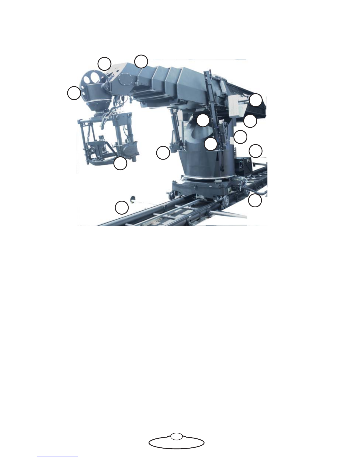
1. Mount the turret - page 8
2. Mount the main shaft on the turret (if it is not already on) - page 9
3. Mount the lift ball screws- page 10.
4. Mount the power supply unit and the driver box - page 11
5. Mount the Titan main arm - page 12.
6. Mount the counter-weight mounting bars - page 13
7. Mount the nose - page 13.
8. Mount the bucket - page 15
9. Mount the head - page 17.
10. Add the counter-weights - page 14
11. Connect the cables - page 18.
12. Mount Titan on a track - page 21.
Page 13
Titan Quick Start Guide
8
Mounting the turret
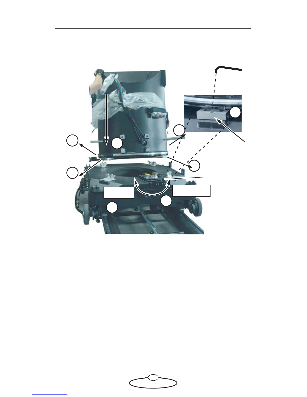
1. Make sure the rotation motor lever is in the anti-clockwise
(Disengaged) position.
2. Make sure all four turret bolt retainers are fully extended outward.
3. Lower the turret onto the base. Ensure that the slip rings line up
with the motor connectors.
4. Press the four turret bolt retainers all the way into the turret, and
tighten the bolts down into the base.
5. Move the rotation motor lever to the Engaged position taking care
that the gears underneath the turret mesh correctly.
Rotation motor
lever
2
5
Disengaged
Engaged
2
4
Press in
3
1
Tu r r et
Base
2
2
Page 14
Titan Quick Start Guide
9
Mounting the main shaft
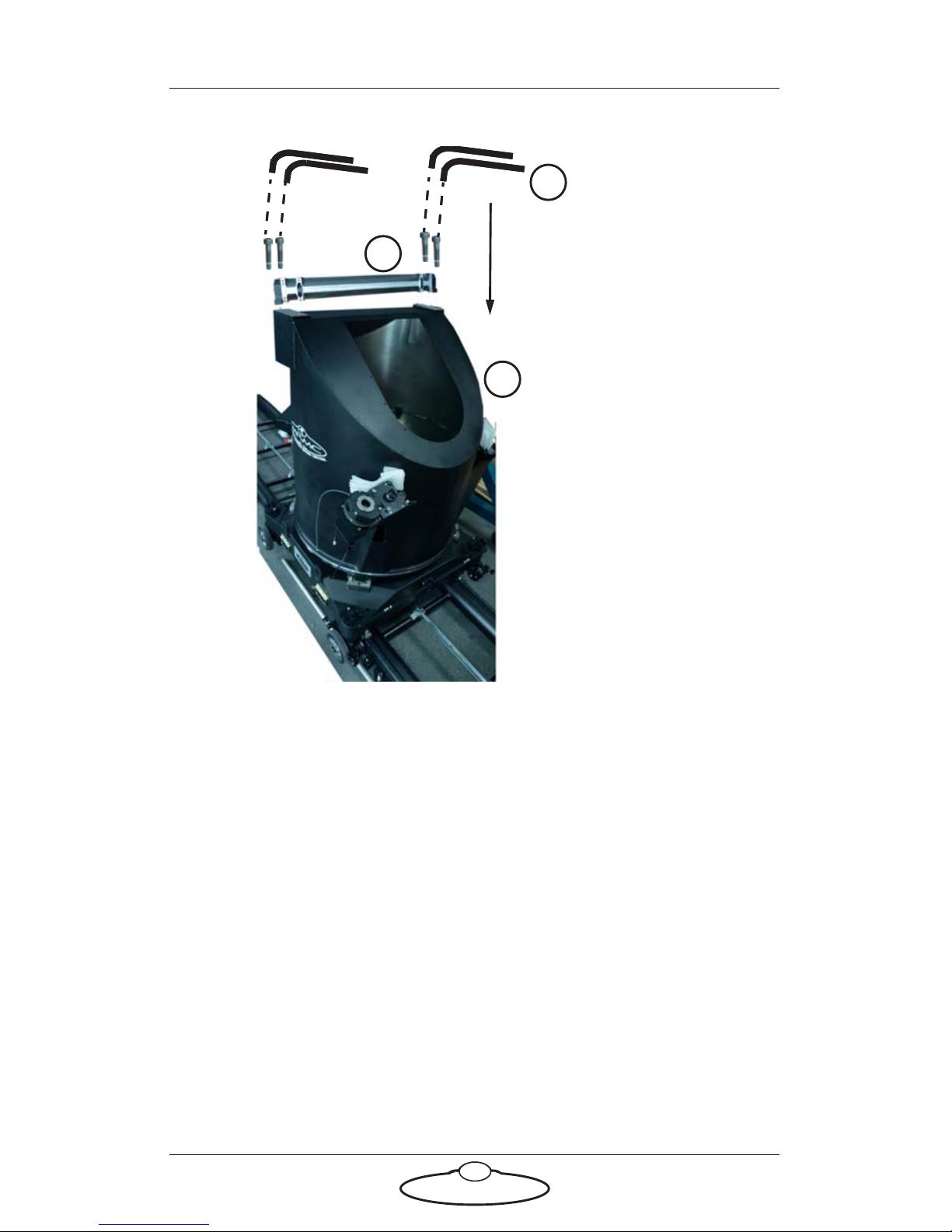
1. Remove the inspection cover from the turret.
2. Place the main shaft on top of the turret aligning the screw slots.
3. Insert and tighten the two bolts on each side of the main shaft to
secure it to the turret. The front bolts should have nylocs
underneath after bolting in place.
1
2
3
Page 15
Titan Quick Start Guide
10
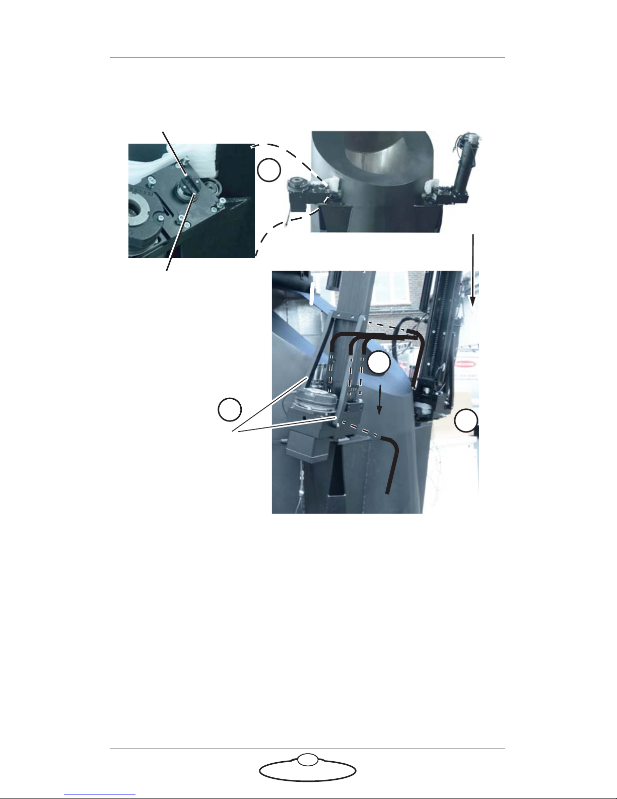
Mounting the lift ball screws
1. Insert the lift ball screw down into the slotted coupling on the
belt box. Ensure that the hole lines up with the dowel on the gear
box housing.
2. Tighten the four bolts on the belt box to hold it in place.
3. Add the two brace pieces to further secure the lift ball screws to
the belt box.
4. Repeat these steps for the second lift ball screw.
1
3
Brace pieces
Slotted coupling
2
Dowel
Slotted coupling
4
Page 16
Titan Quick Start Guide
11
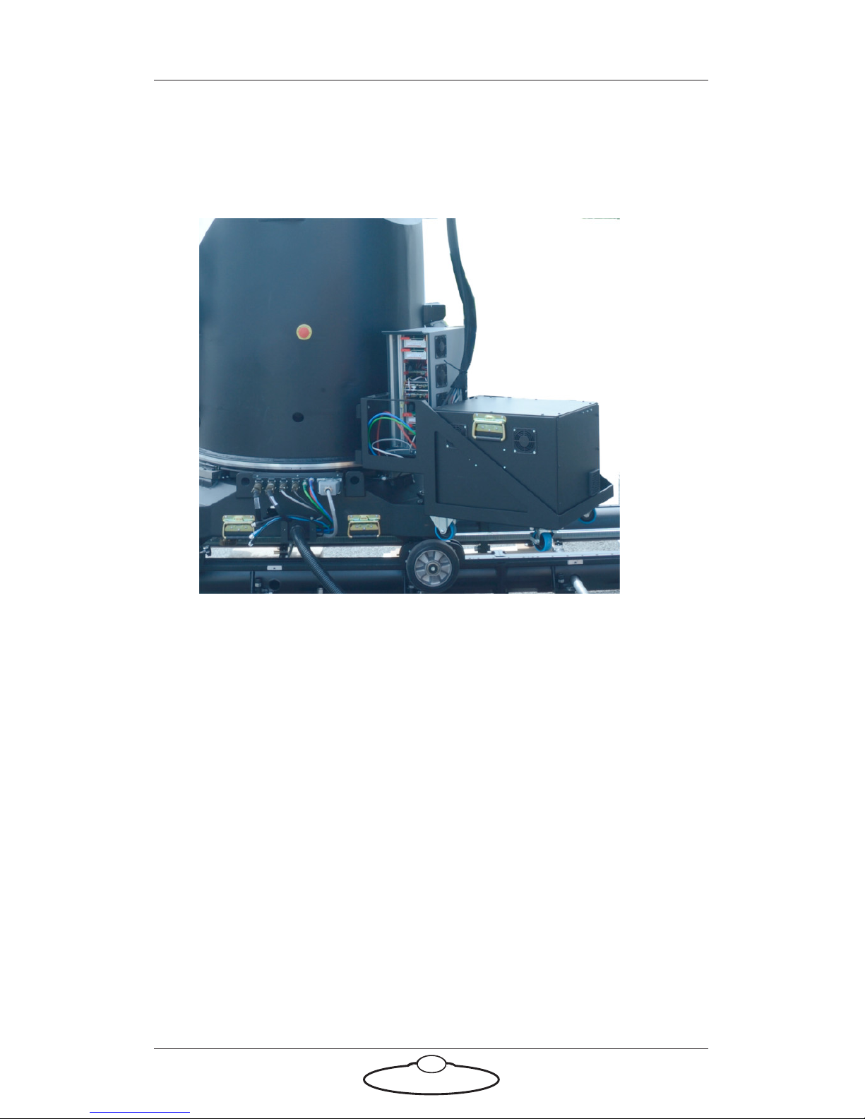
Mounting the Power Supply Unit and the driver
box
1. Put the bracket on the two mounting hooks on the rear of the turret.
2. Lift the PSUs and place them in the bracket.
Page 17
Titan Quick Start Guide
12
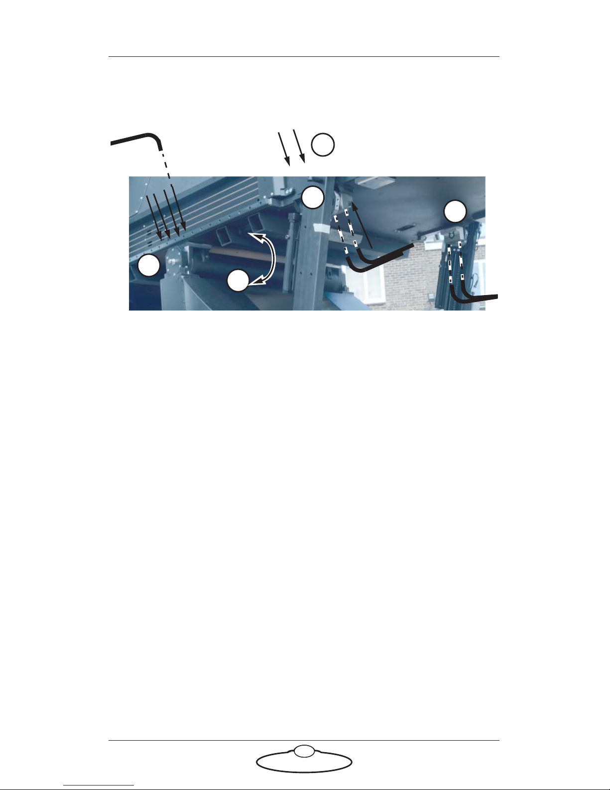
Mounting the Titan main arm
1
4
2
3
3
Place the retracted arm
on the main bearing
1. Rotate the main shaft on top of the turret so the brackets on the
main shaft face up.
2. Using a gantry lift, place the retracted arm without mounting bars
onto the brackets on the main shaft.
3. Insert and tighten the eight bolts that hold the arm on the main
shaft.
4. Line the mounting block on the lift ball screws on either side to the
shoulder of the arm and tighten the captive bolts.
Page 18
Titan Quick Start Guide
13
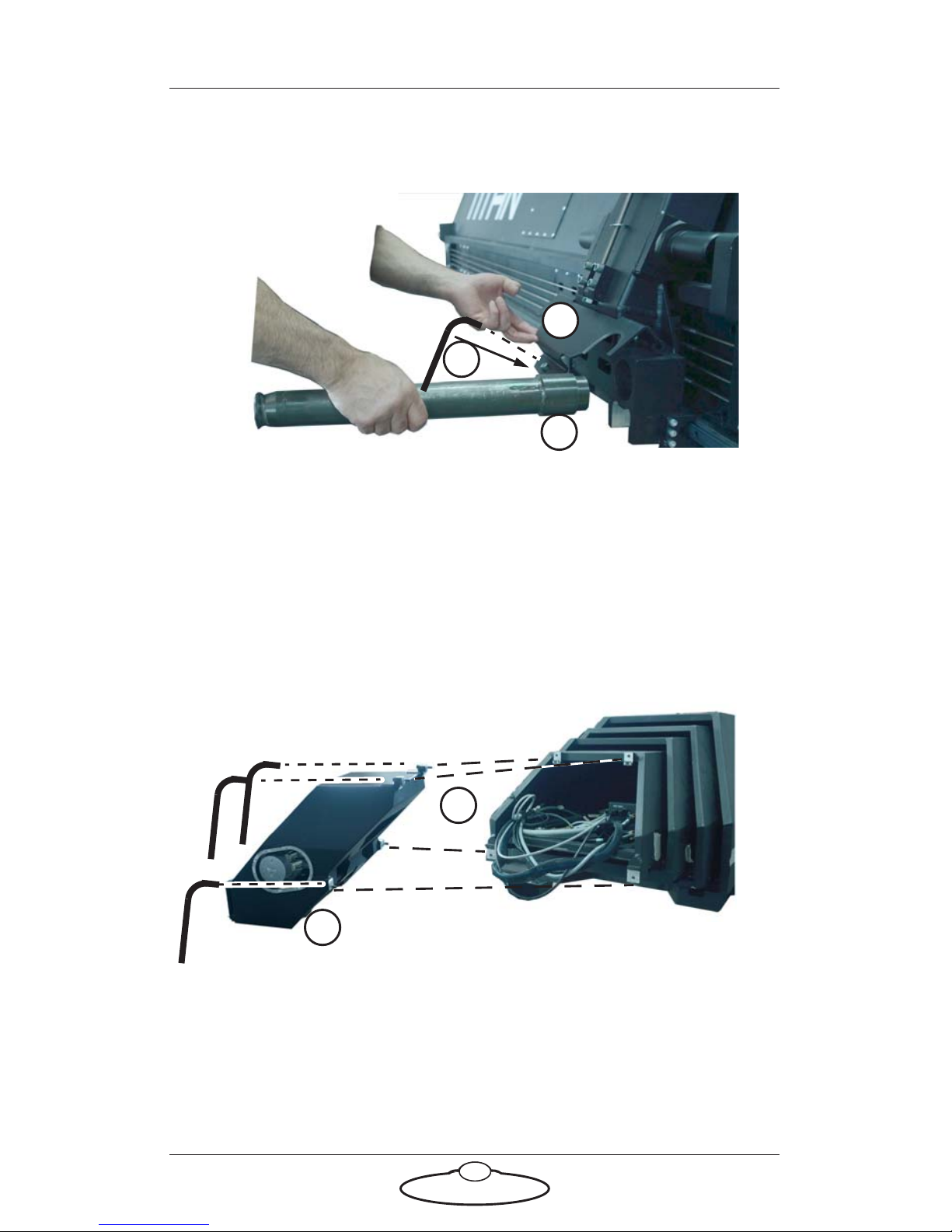
Mounting the counter-weight mounting bars
1
1
2
1. Lift up the weight clamp on the Titan arm and insert the
counter-weight mounting bars in the two slots on each side.
2. Release the clamp and tighten the single bolt to secure the
counter-weight mounting bars.
Mounting the nose
1
2
1. Lift nose to align it to the mounting bracket on the main arm.
2. Insert and tighten the four bolts that hold the nose and the arm.
Page 19
Titan Quick Start Guide
14
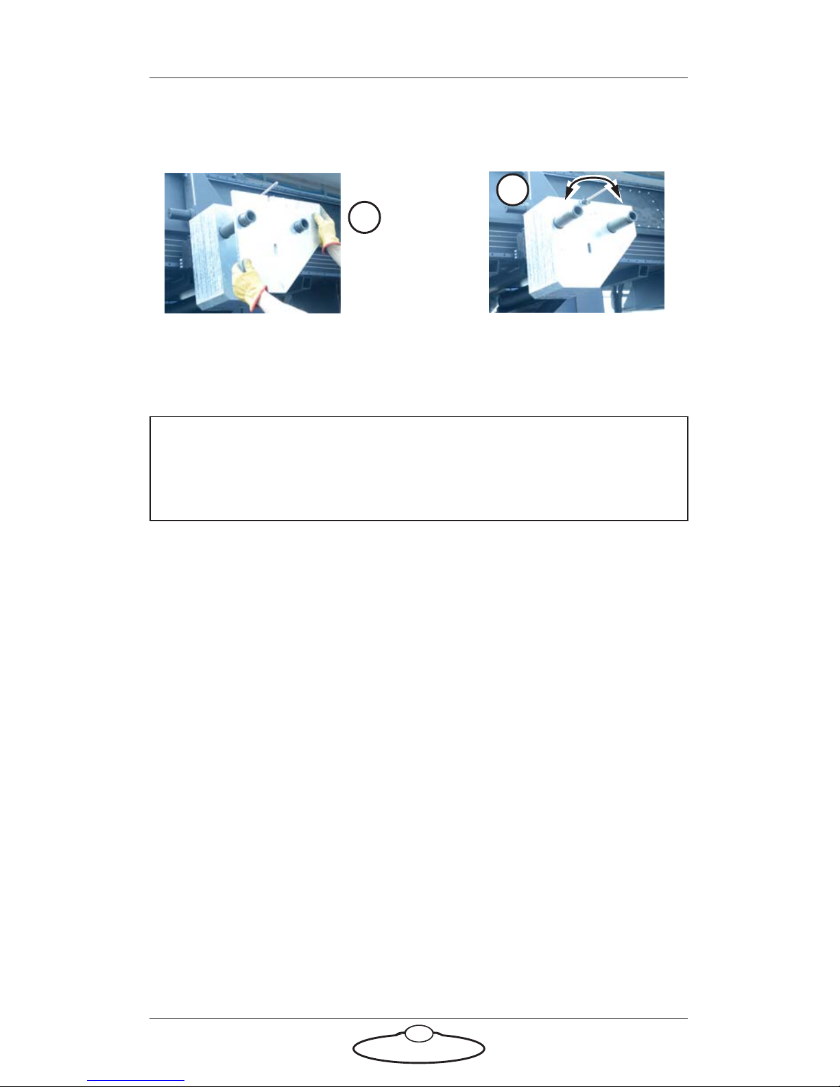
Adding the counter-weights
1. Add the counter-weights to the counter-weight mounting bars.
These should be about 16 when using the Ulti-head and 20 when
using the Guinness head.
2. Lower the clamp and tighten the nut to secure the counter-weights.
Note
Ensure that the sloping sides of the counter weights are towards the
rear end of the Titan arm.
1
2
Page 20
Titan Quick Start Guide
15
Mounting the bucket
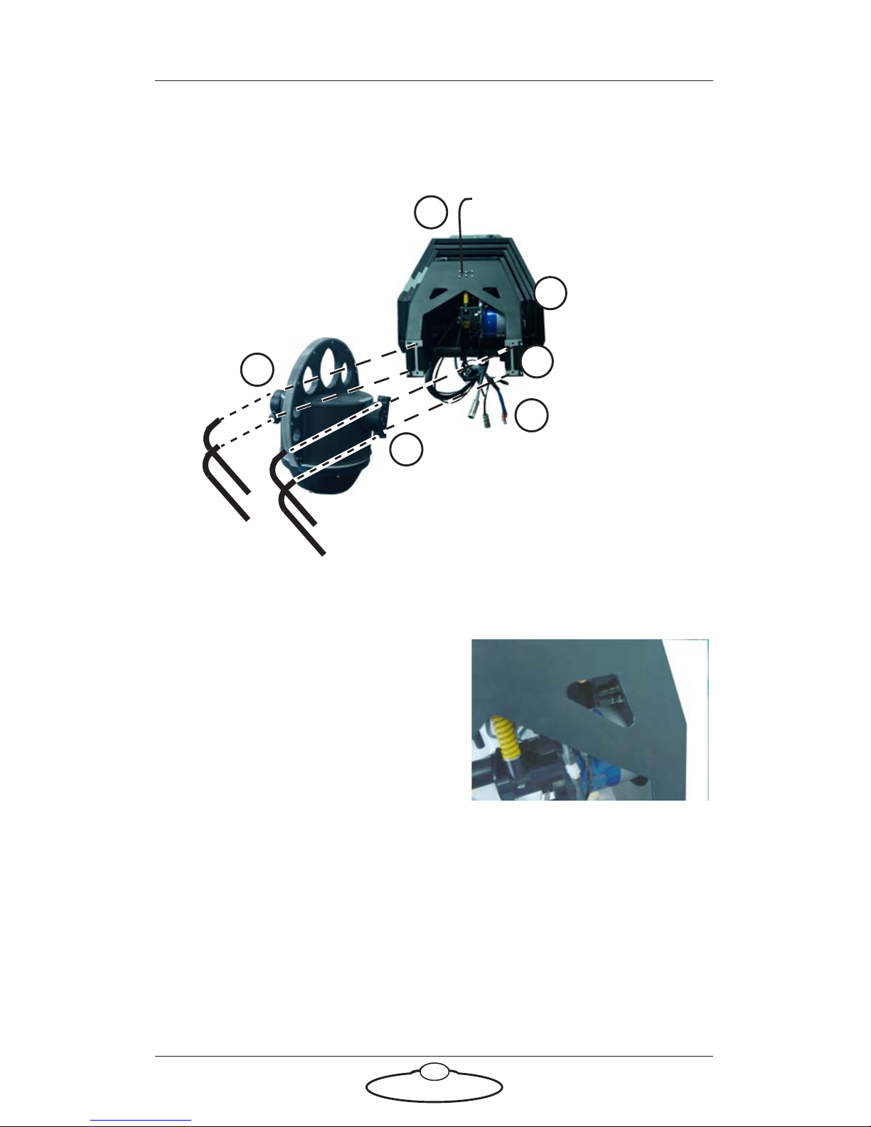
1. Pull out the cables from the Titan arm through to the nose.
2. Plug the connectors for the outer
arm into the nose. These are the
power connector, the encoder
connector for the outer arm and
the limit switches.
3. Retract the overcenter lock mesh bracket and secure it by inserting
an allen key into the slot.
4. Align the bucket to the nose bracket and tighten two bolts on each
side of the bracket.
1
2
3
Allen key inserted in
the slot
4
4
4
Page 21
Titan Quick Start Guide
16
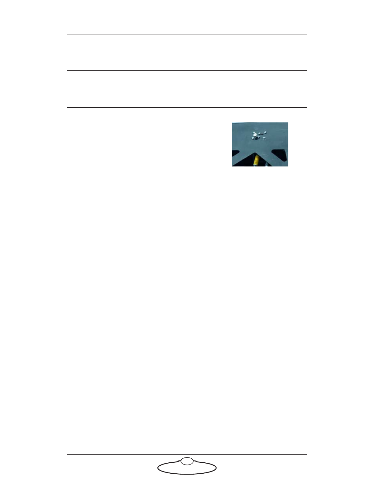
5. Remove the allen key and pull the lever to lock the gear into mesh.
You will need to reach in to the lever from below the nose.
6. Replace the safety bolt.
Tip
Swing the bucket slightly to ensure that the mesh lines up
Page 22
Titan Quick Start Guide
17
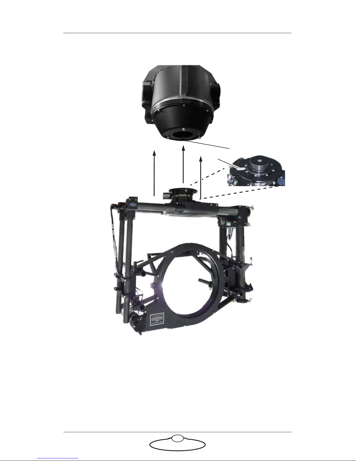
Mounting the head
Key
Slot
Example: Ulti-Head
Mount the head to the bucket using the three bolts, making sure that
the key on the head fits into the slot in the bucket.
Page 23
Titan Quick Start Guide
18
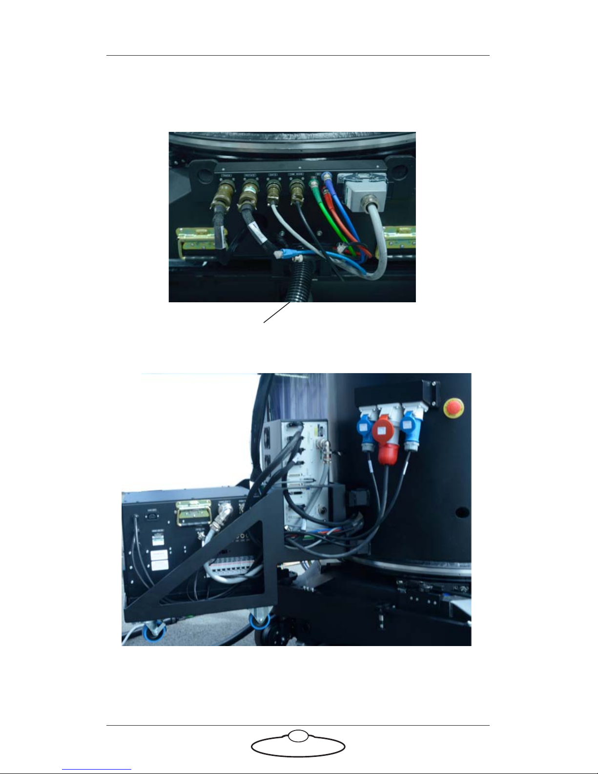
Connecting the cables
Picture of umbilical - base connections:
Picture of PSU-Turret-Titan Arm connections
Milo Base
Umbilical cable wrap
Page 24
Titan Quick Start Guide
19
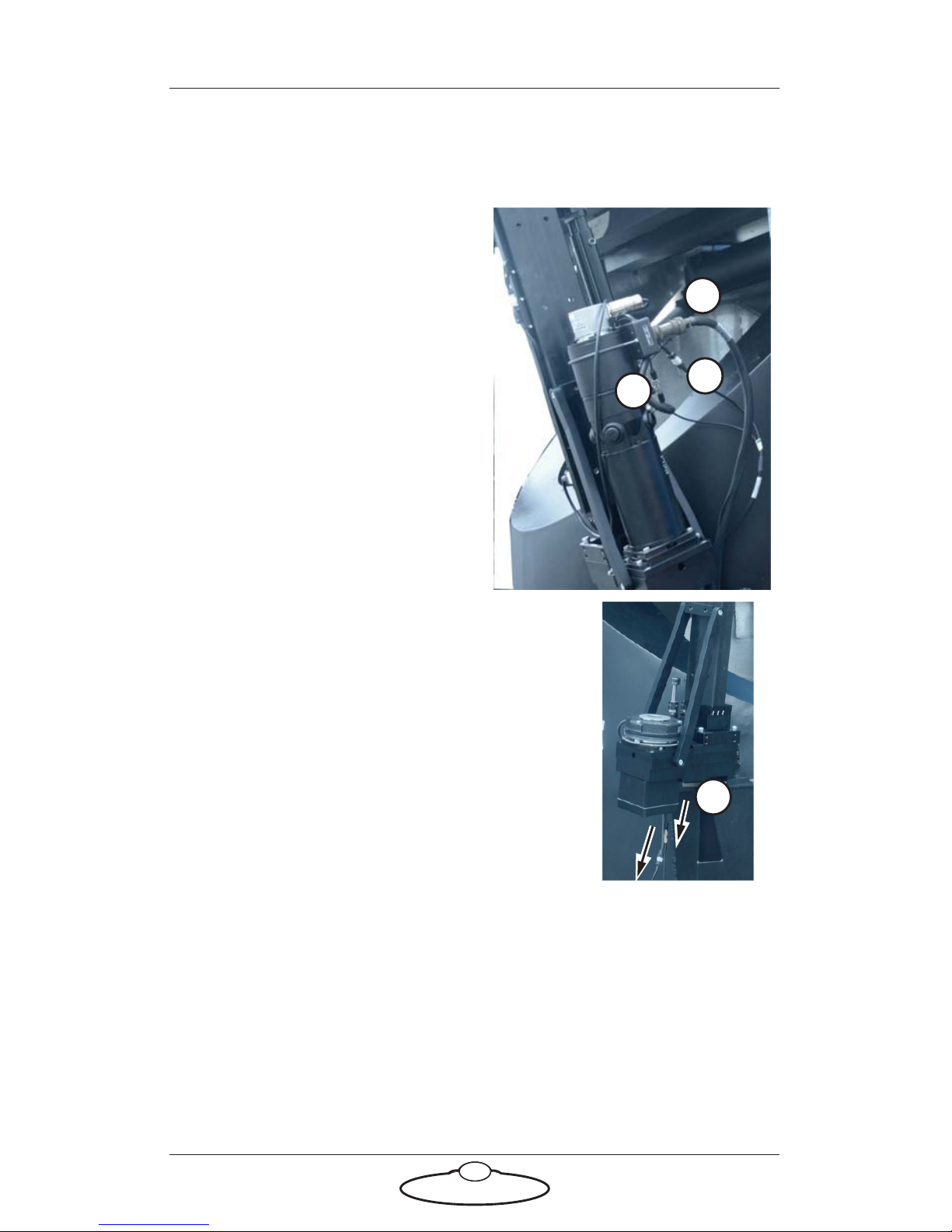
Lift ball screws connections
Lift motor connections
1. Attach the cable to the Limit
and Datum connector.
2. Attach the brake and speed
sensor cable to the connector
and tighten it.
3. Attach the lift motor cable to
the lift motor.
4. Attach the break and speed sensor cables
to the connectors on the other side of the
turret.
3
1
2
4
Page 25
Titan Quick Start Guide
20
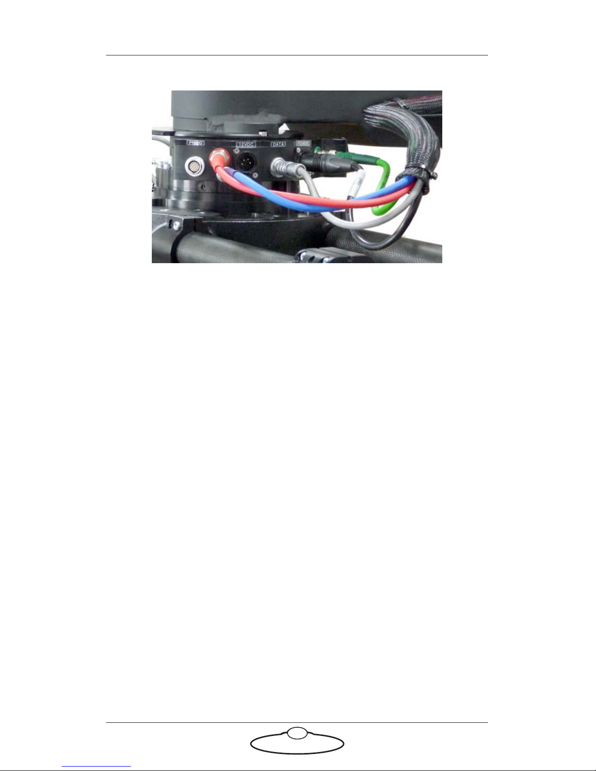
Connections to the slip ring base on the Ulti-head
Attach the cables to the head and camera. Here is an example of the cables
attached to the Ulti-head.
Page 26
Titan Quick Start Guide
21
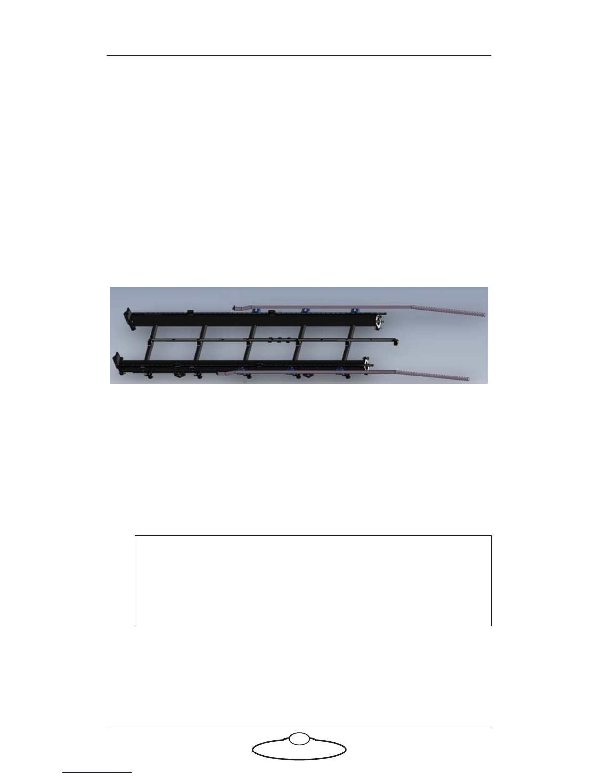
Mounting the rig on a track
Mounting the rig on the track bearings
1. Roll the rig to a position just off the end of the track, ensuring that
the track pinion on the rig is on the correct side of the track.
2. Mount the ramp-ups on to the side of the track. Roll the rig over to
the ramp- ups to raise the rig high enough over the track so that the
track motor gear on the underside of the rig completely clears the
rack (the middle rail on the track). Push the rig to the position over
the ramp-ups so that the track motor gear on the Milo underside is
on the toothed side of the rack. Do not engage the teeth yet; just
make sure Milo is the correct way around for the track.
3. Push the rig to the levelled part of the ramp-ups and whilst in the
position push the four track bearings under the four corners of the
Milo base making sure that all four bearings are aligned with the
corners of the Milo base, and the track motor gear on the underside
of Milo clears the rack. (The track motor gear is on bearing rails so
you can slide it out of the way to clear the rack.)Drop the four track
bearing bolts in their slots in the Milo without tightening them yet
ensuring they line up with the track bearings.
4. Push Milo further over the ramp-ups on to the bearings on the track
so it drops fully. Tighten the four track bearing mounting bolts at the
corners.
Hint
Always mount and remove the track bearings with care. Try to
keep them squared up and in-line with the bearing rail to avoid
damaging them or loosing a bearing.
Page 27

Titan Quick Start Guide
22
5. Feed out enough umbilical cable from your control area to reach the
entire length of the track without stretching the cable. Make sure the
area alongside the track is clear so that the umbilical cable doesn’t
catch on anything when Milo drags it alongside the track.
6. Attach the track motor pinch wheel on the underside of Milo,
described in the next section.
Caution
Manually push the rig to ensure there is no resistance in the track. If
there is, you might need to level the track.
Page 28
Titan Quick Start Guide
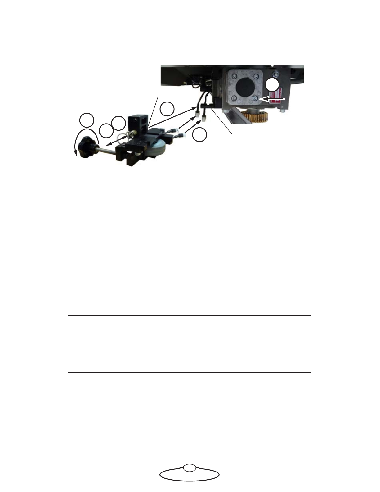
23
Attaching the track motor pinch wheel and its connectors
1. On the separately supplied pinch wheel assembly, remove the brass
retaining pin by pulling on the ring.
2. Mount the pinch wheel assembly onto the track motor on the Milo
underside, by sliding the track motor gear against the rack (the
motor is on bearing rails) and putting the pinch wheel Socket onto
the track motor Mounting bar.
3. Replace the retaining pin in the pinch wheel assembly by pushing on
the ring (not the locking sleeve), to hold the assembly in place on
the track motor.
4. Hand-tighten the pinch wheel adjustment bolt so that the rubber
wheel presses firmly against the smooth side of the rack. This holds
the track motor gear firmly against the toothed side of the rack.
5. The pinch wheel assembly has sensors for detecting the Limit (L)
and Datum (D) magnets on the track. Connect the cables for these
sensors to the corresponding connectors on the Titan underside,
and use cable ties to hold them securely up away from the track.
Hint
Do not tighten the pinch wheel too much to prevent damage to the
pinch wheel. It should only be so tight that you are able to turn the
wheel and then do about an additional half turn.
Mounting bar
Socket
1
2
5
4
2
3
Page 29
Titan Quick Start Guide
24
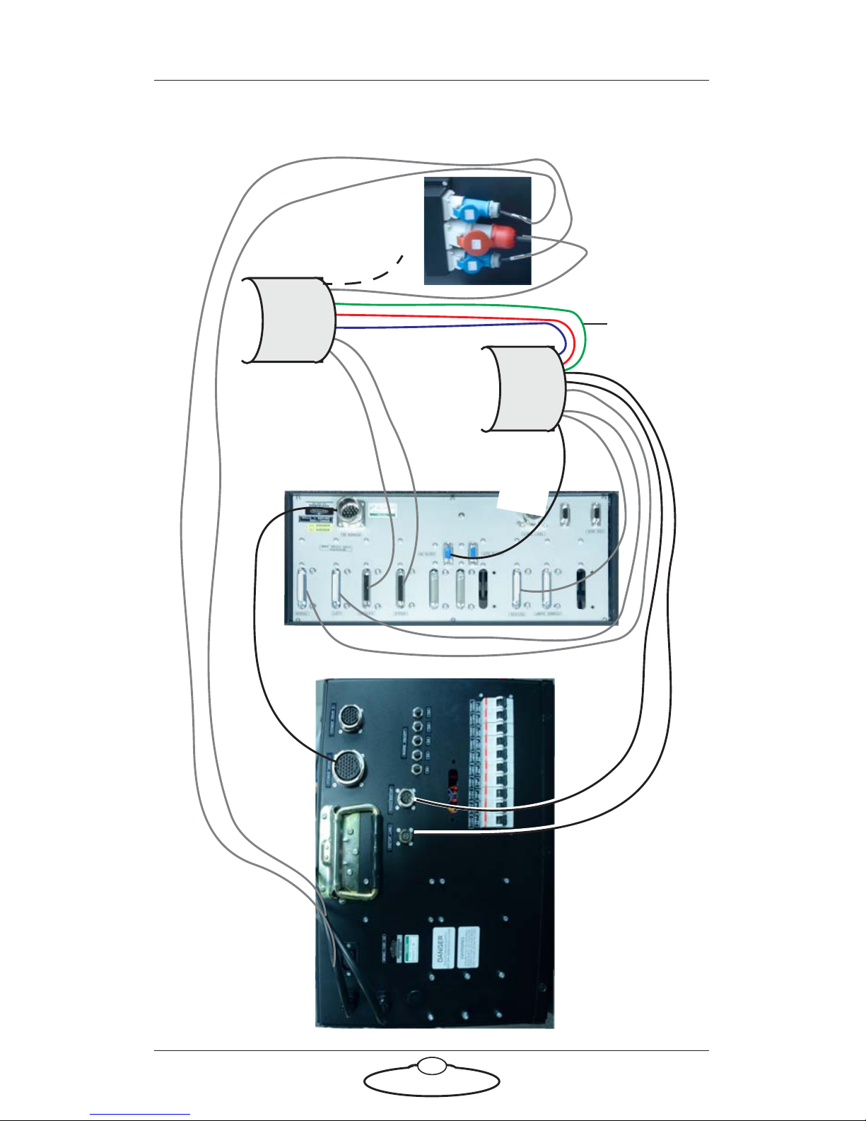
Connecting the cables
3-p
h
a
s
e po
wer
t
o T
i
t
an a
r
m
Da
t
a
lin
k
I
n
pu
t
To T
i
t
a
n
ar
m
S
in
g
le-ph
a
s
e po
wer t
o PS
U
EST
OP
R
OO
T/ESTOP
P
o
wer f
o
r Dri
v
er B
o
x 1
TR
ACK
LIFT
EX
TEND
ANGLE
V
ide
o
cab
les to
t
h
e h
e
ad
R
O
TATE
F
r
o
m
M
ilo
t
ur
r
et
C
a
b
le
w
ra
p
C
a
b
le
w
ra
p
E
TH*
Page 30
Titan Quick Start Guide
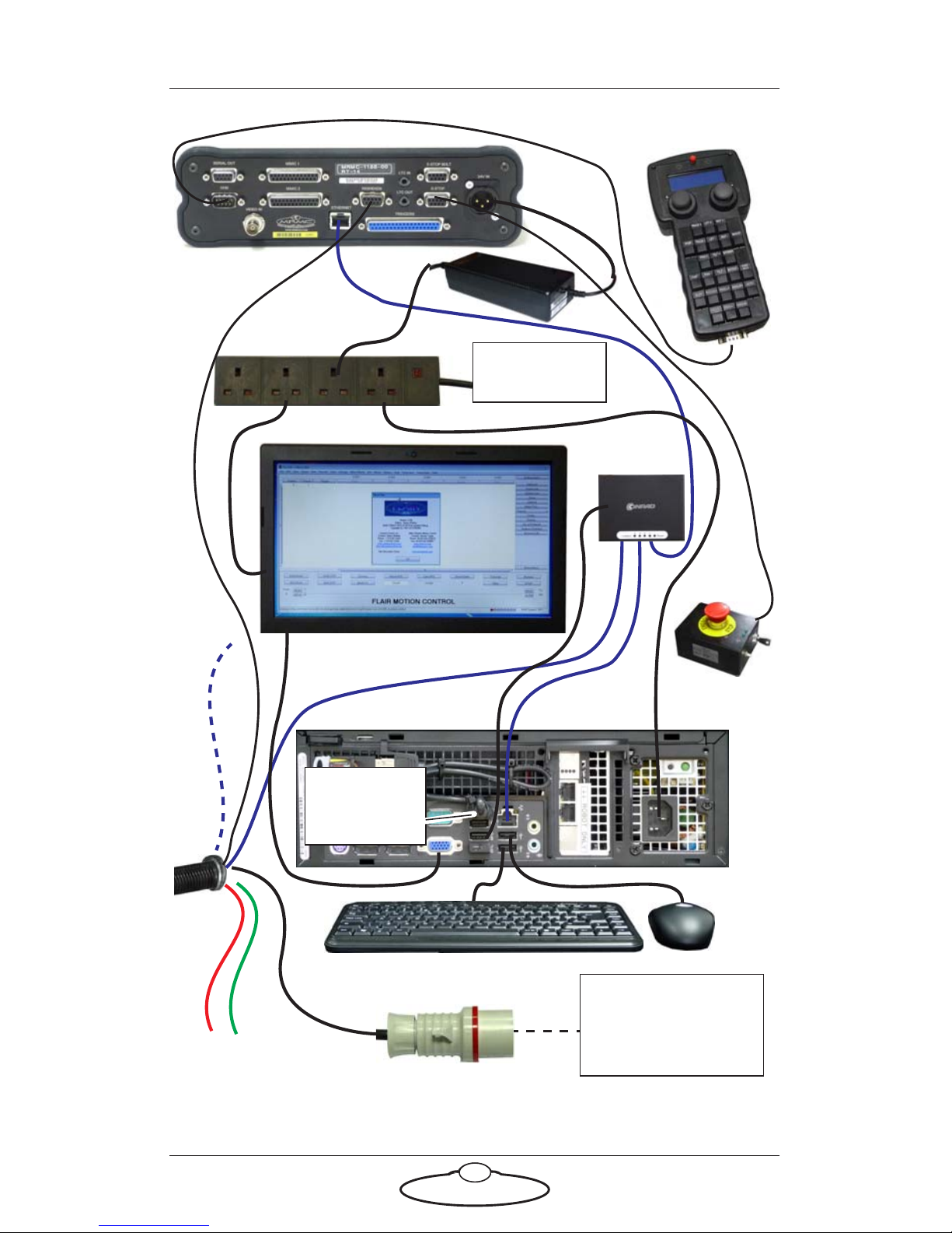
25
E-STOP
Ethernet
Power Supply:
400 Volt, 3-phase,
5-wire including
Neutral and Earth
VIDEO SIGNALS
Power Supply:
120-240 Volts
hub
5V
Flair dongle
cable in USB
port
RT-14
Hand Held Box
Ethernet for Camera
E
THERNET
POWER
ETHERNET
24V IN
D
A
TALINK
Page 31
Titan Quick Start Guide
26
Starting up the Milo-Titan system
Once you have attached all the cables, you power up the rig by switching
on the components in the order described below.
1. Make sure you have secured the area around the rig.
Put up guard rails around the rig (and the track) as
necessary, and tell others on the set that you are now
powering up the rig.
2. Ensure that the E-stop by the computer stack is pushed in.
3. Push in all the Mains switches on the PSU.
4. Turn on all the breakers from left to right.
5. Power up the Flair computer system and all of its components,
including the RT-14 interface box. You can do this while the rig is
powering up (step 3 and 4).
6. On the Flair PC, start the Flair application by double-clicking on the
Flair icon on the Desktop.
Flair automatically loads the relevant firmware into all attached axis
boards, including:
The quad board that runs the track motor
The Ulti-head that is mounted on the Titan arm
Any additional interface boxes that are attached to the
computer stack
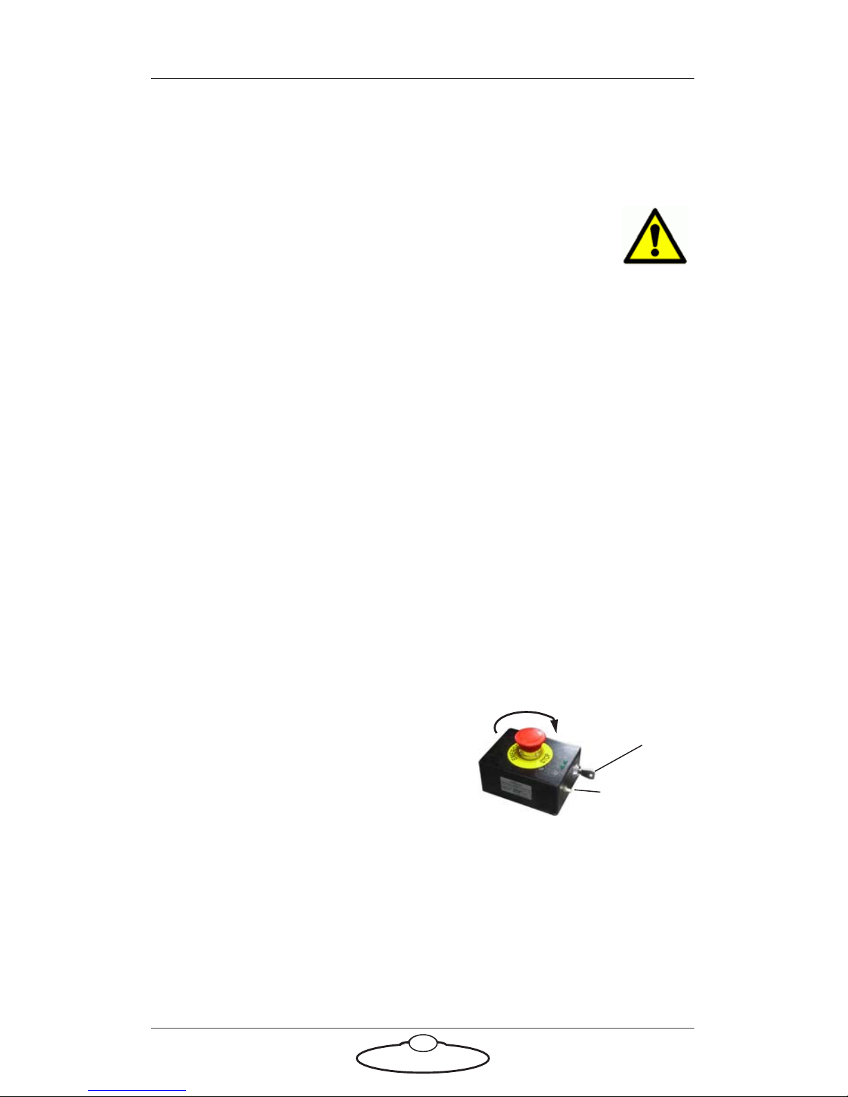
7. Release the E-stop that is plugged
into the computer stack, by turning
the button clockwise until the red
button pops up and then pressing
the Reset button. Also make sure the
key is in the vertical position.
8. Zero the axes as required in Flair. For example, to zero the Track
axis:
To do this you use the Zero > Home Axis > Track menu
option.
Any external Lens Control Motors (LCMs) that you are using.
To zero these you first set the focus to infinity (), zoom to
Reset button
Key
Page 32
Titan Quick Start Guide
27
wide-angle (zoomed out all the way), iris/aperture to wide
open and then use the relevant Zero > Direct Zero Axis menu
option to set those lens positions as the zero points in Flair.
9. In Flair, move the Titan arm to its home position.
10. Set the soft limits for the rig axes in Flair as required:
Particular axes (if space is limited)
Track limits
Lens Control Motor limits (if using external LCMs)
Milo-Titan start-up summary
1. Secure the area
2. Release the E-stop on the rig
5. Turn switches on the PSU
5. Switch on the Flair PC and RT-14
6. Start Flair
6. Release the E-stop on the computer stack
In Flair:
7. Zero the track and Lens Control Motor axes
8. Home all axes
9. Set the soft limits
The rig is now ready to use.
Hint
• Manually move the arm close to its home
position before Homing it.
• When you home the rig, have one hand ready on the
E-stop in case you need to stop the rig quickly.
Page 33

Titan Quick Start Guide
28
Shutting down the Milo-Titan system
1. Move the rig to its Home position, for both the arm and the track.
or...
If you are going to transport the rig to a new location, put the Titan
arm into its transport position. You can do this either by using Flair
(although you might have to reset the soft limits to reach the
transport position) or by moving the arm manually.
2. In the Flair software, disengage all axes.
3. Press down the E-stop button on the computer stack.
4. Close the Flair software. Ensure that you save any unsaved jobs
before closing Flair.
5. Shut down Windows on the Flair PC.
To remove the rig from the track see Mounting the rig on a track and
follow the instructions there in reverse order, detach the pinch motor
wheels and remove the rig from the track bearings.
Page 34

Titan Quick Start Guide
29
Titan Quick Start GuideTitanQuick Start Guide
Appendix 2 Specifications
Weight: 1700kg including trolley wheels and 32 sliding weights on each
side
Weight (without counter-weights): 675kg
Payload (camera and head): 50 Kg
Power requirements: 400 Volts 3-phase (earthed/grounded) 7KW.
Temperature range: 0-45 °C (32-113 °F)
Humidity tolerance: 0% to 85% relative humidity, non-condensing
Rotate 360 degrees
Lift 1m
Angle 138.5 degrees
Dimensions:
Length (Arm fully extended): 11.5m
Length (Arm retracted): 4.5m
Width (With counter-weight mounting bars): 1.85m
Height (horizontal arm): 2.46m
Height (arm fully extended at maximum height): 7.9m
Page 35

Titan Quick Start Guide
30
Notes
Page 36

Titan Quick Start Guide
31
Notes
Page 37
Mark Roberts Motion Control Ltd.
Unit 3, South East Studios, Blindley Heath, Surrey RH7 6JP
United Kingdom
Telephone: +44 (0) 1342 838000
www.mrmoco.com
 Loading...