

Page 1
Quick Start Guide
Document version: SFH50-QSG-20150811
Part number: MRMC-1166-00
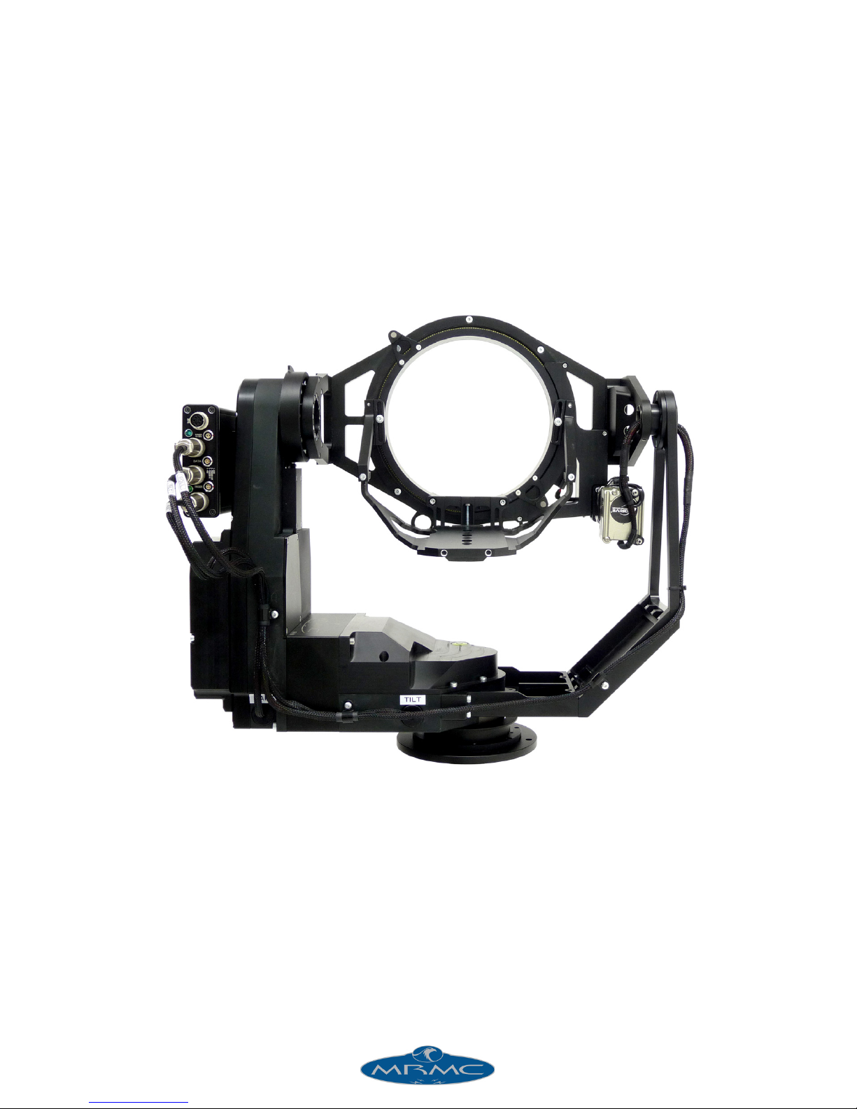
SFH-50 HEAD
Page 2
ii
SFH-50 Quick Start Guide
Document version: SFH50-QSG-20150811
Part number: MRMC-1166-00
© 2015 Mark Roberts Motion Control Ltd. All rights reserved.
No part of this publication may be reproduced, transmitted, or translated
by any means — graphical, electronic, or mechanical — including
photocopying, recording, taping, or storage in an information retrieval
system, without the express written permission of Mark Roberts Motion
Control.
Although every care has been taken to ensure that the information in this
document is accurate and up to date, Mark Roberts Motion Control
continuously strives to improve their products and may make changes to
the hardware, firmware, and software described in this document. Mark
Roberts Motion Control therefore cannot be held responsible for any
error or omission in this document.
All product names mentioned herein are the trademarks or registered
trademarks of their respective owners.
Contact information
Mark Roberts Motion Control Ltd.
Unit 3, South East Studios
Blindley Heath
Surrey
RH7 6JP
United Kingdom
Telephone: +44 (0) 1342 838000
E-mail: [email protected] (sales and general enquiries)
[email protected] (customer support)
Web: www.mrmoco.com
www.mrmocorentals.com
Page 3

SFH-50 Quick Start Guide
iii
SFH-50 Quick Start GuideSFH-50Quick Start Guide
Contents
Chapter 1 Quick Start..................................................................... 1
Safety........................................................................................ 1
Overview .................................................................................1
Setting up the hardware ........................................................2
Connecting the cables ...........................................................9
Quad-box example, for an SFH-50 head with
stepper motors...............................................................9
Ulti-box example, for an SFH-50 head with
servo motors................................................................11
Your first session ..................................................................12
Subsequent sessions .............................................................15
Appendix 1 Troubleshooting........................................................... 16
Typical symptoms, causes, and actions .............................16
Working with Local Area Networks..................................17
Introduction to LAN addresses ................................17
Managing LAN addresses with Flair........................19
Appendix 2 SFH-50 Panel ............................................................... 23
Introduction to SFH-50 connections ................................23
Interface boxes ............................................................23
Notes on head-controller communication
methods........................................................................23
Quad-box and Octo-box connector summary ................24
Quad-box and Octo-box connector pin-out
information...........................................................................26
Stepper motor connector...........................................26
Power 18-36 Volts connector ....................................26
Serial RS232 connector ..............................................26
Trigger connector .......................................................27
Data In connector.......................................................27
Data Out connector....................................................27
Ulti-box connector summary.............................................28
Ulti-box connector pin-out information ..........................30
Servo motor connector ..............................................30
Program serial connector ..........................................30
Power connector .........................................................31
Camera Accessory connector....................................31
Data In connector.......................................................32
Page 4

SFH-50 Quick Start Guide
iv
Appendix 3 Specifications............................................................... 33
Page 5

SFH-50 Quick Start Guide
1
SFH-50 Quick Start GuideSFH-50Quick Start Guide
Chapter 1 Quick Start
Safety
• Do not use around flammable gas. All electrical equipment can
generate sparks that can ignite flammable gas.
• The head has powerful motors that can pinch, so take care not to get
your hands trapped in the head or cabling.
• Keep the equipment dry, and do not use with wet hands.
• Keep cables tidy. Use cable ties to keep them out of harm’s way. If
you have a head with slip rings then make use of them; avoid
running any cables between the base and the rotating head or
camera.
Overview
Thank you for using the SFH-50 robotic camera head from Mark Roberts
Motion Control (MRMC). The SFH-50 head is designed for reliable
day-in, day-out use in professional studio and Outside Broadcast
environments
You can use the Ethernet connection on the SFH-50 head to connect
directly or remotely to any MRMC controller, such as the Large Flat Panel
(LFP), MSA-20 Handwheels, Mini MSA, or a PC running Flair Motion
Control Software.
Page 6
SFH-50 Quick Start Guide
2
Setting up the hardware
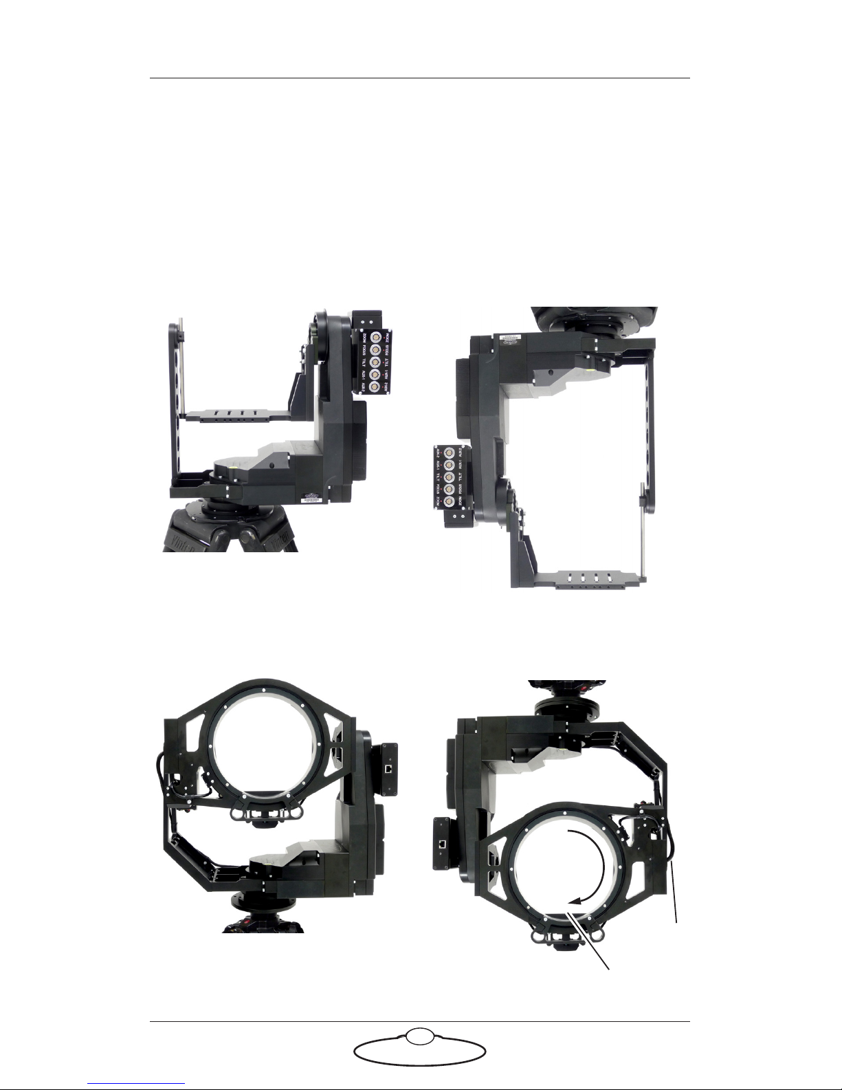
1. Mount the SFH-50 head onto your choice of support, such as a
heavy-duty tripod or metal plate. The head can be over-slung
(sitting on a tripod or platform) or under-slung (hanging from its
mount).
SFH-50 with Support Arm:
SFH-50 with Roll Ring:
Over-slung
Under-slung
Over-slung
Under-slung
Roll
Cable
Platform
180°
Page 7
SFH-50 Quick Start Guide
3
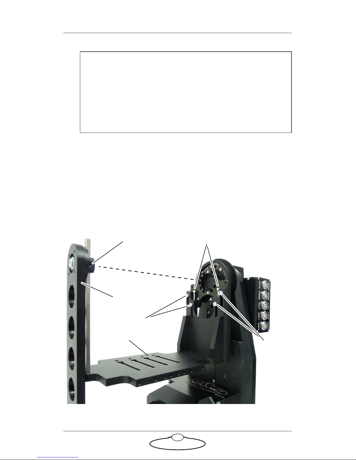
2. Adjust the height of the camera platform relative to the head, so that
the camera lens will be at the same height as the Tilt axis (and
centred in the optional Roll Ring) when the camera is mounted later.
Do not adjust the platform height when a camera is mounted.
To adjust the height on an SFH-50 with a Support Arm, loosen the
five retaining bolts that hold the camera platform in place (one on
the Support Arm, then four on the main platform arm), turn the
two height adjustment bolts to achieve the platform height you
want, then re-tighten the five retaining bolts.
Hint
If your SFH-50 has a Roll Ring and you use under-slung
mounting, move the camera platform to the bottom
(lowermost) position by manually rotating the Roll Ring 180°.
Do not move the camera platform to the bottom by inverting
the Tilt, as doing this will twist the Roll motor cable that goes
through the Tilt axle.
Loosen
Loosen
Platform
Loosen this one first,
tighten last
Height adjustment bolts
T
i
l
t axi
s
Support Arm
Platform
Page 8
SFH-50 Quick Start Guide
4
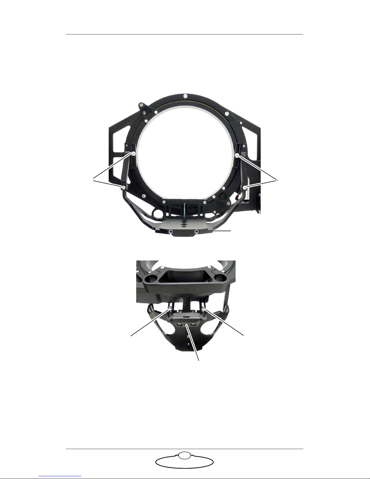
To adjust the height on an SFH-50 with a Roll Ring, loosen the six
retaining bolts that hold the camera platform in place (four in the
rear, two in the front), turn the height adjustment bolt to achieve the
platform height you want, then re-tighten the six retaining bolts.
Loosen
Loosen
Rear view:
Loosen
Loosen
Height adjustment bolt
Front view:
Platform
Page 9
SFH-50 Quick Start Guide
5
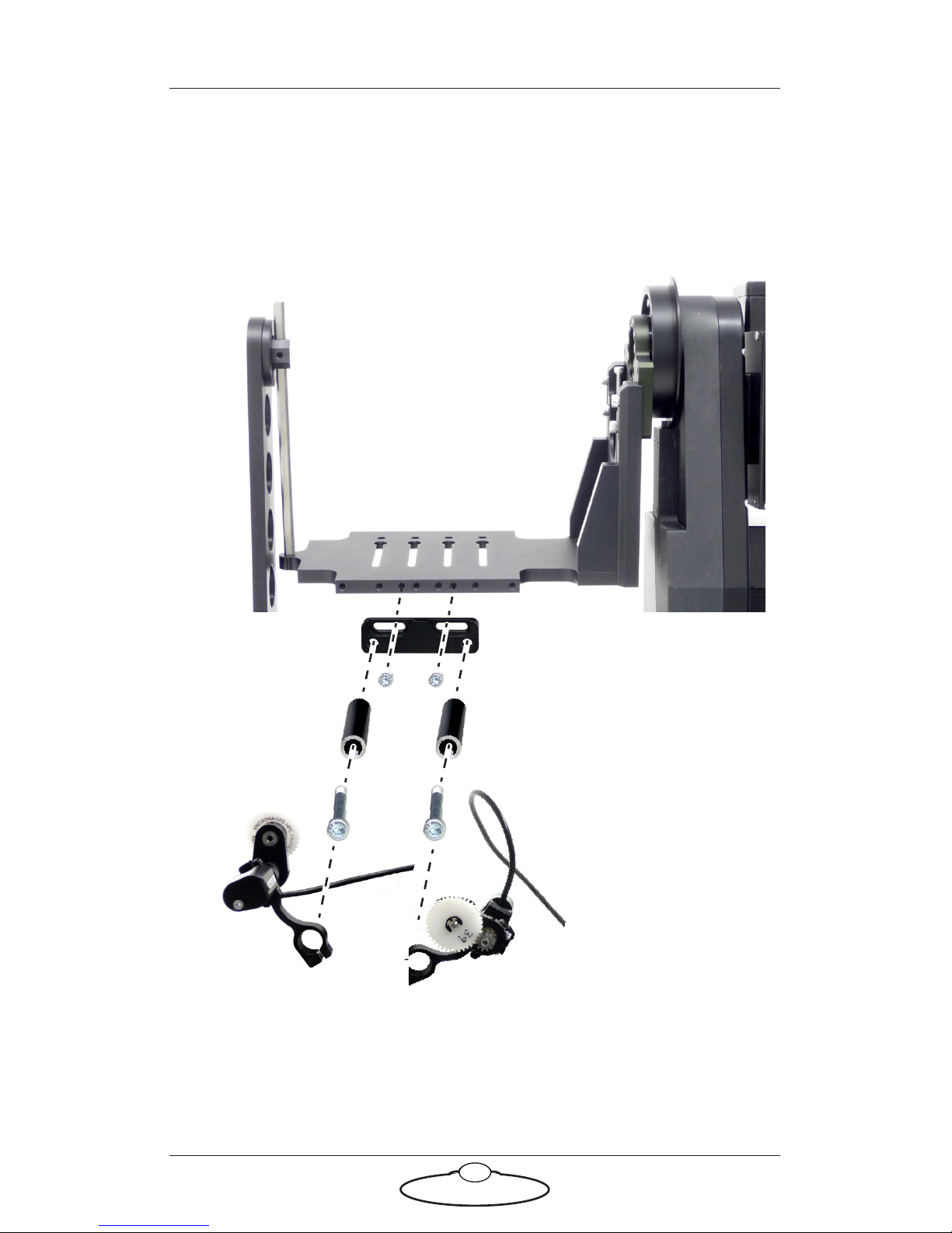
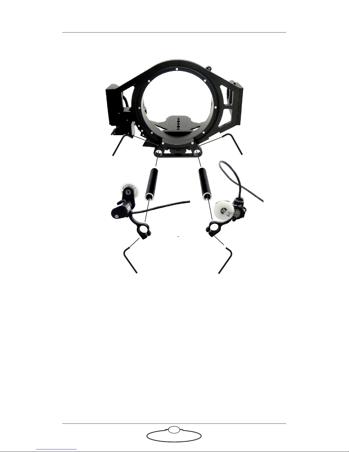
3. If you are using external Lens Control Motors (LCMs) that are
mounted on the head, bolt the mounting rods onto the head, then
mount the LCMs onto the rods in approximately the correct
position. You can fine-tune the position later.
SFH-50 with Support Arm:
Mounting
rods
LCM: Zoom
LCM: Focus
Page 10
SFH-50 Quick Start Guide
6
SFH-50 with Roll Ring:
Mounting
rods
LCM: Zoom
LCM: Focus
Page 11
SFH-50 Quick Start Guide
7
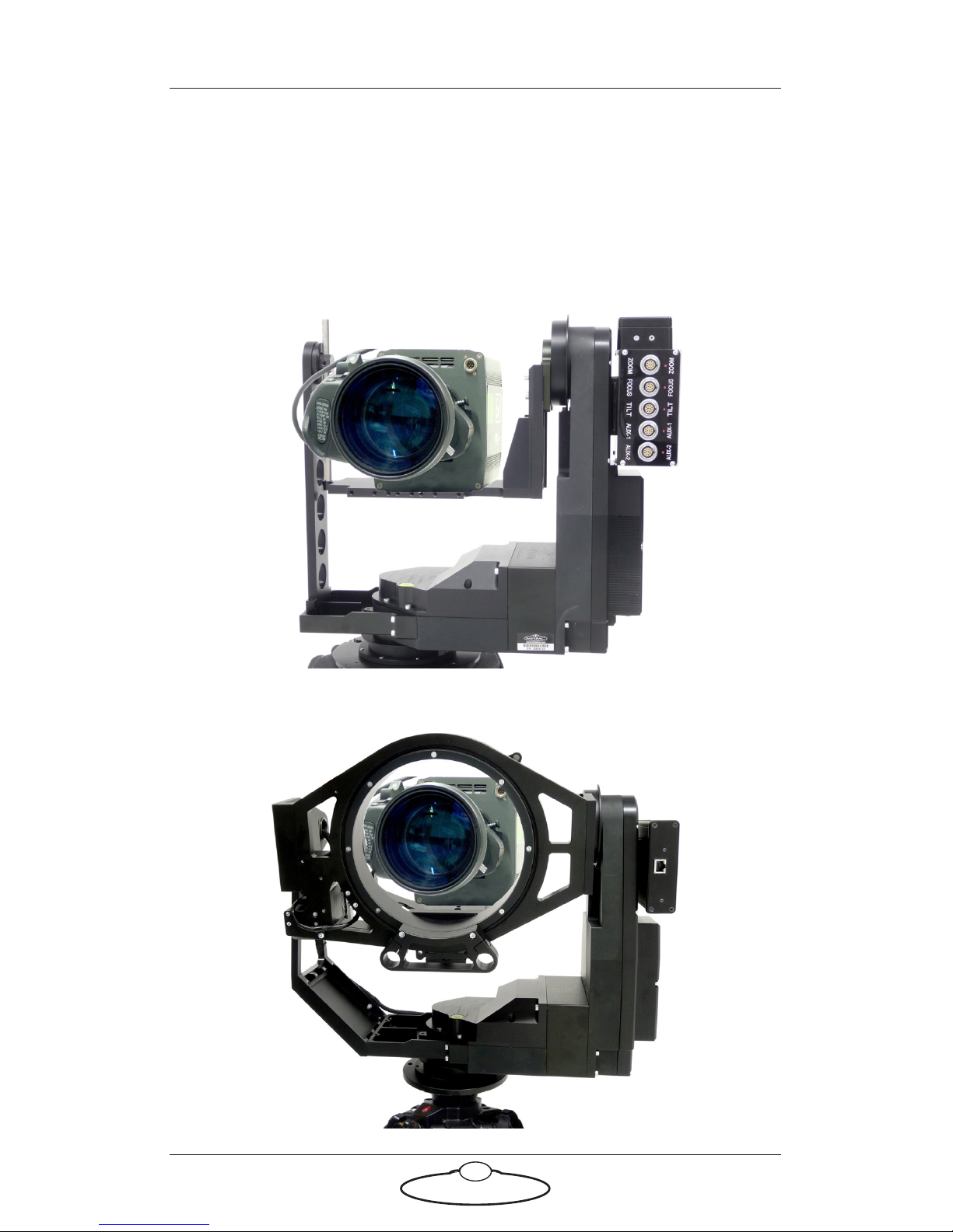
4. Place the camera on the platform, move the camera forward or
backward to balance the platform in Tilt, then insert the camera
mounting bolts under the platform and into the bottom of the
camera housing and tighten firmly.
SFH-50 with Support Arm:
SFH-50 with Roll Ring:
Page 12

SFH-50 Quick Start Guide
8
You normally mount the camera with the lens pointing through the
Roll Ring, but you can mount it backwards (pointing away from the
ring) if you want.
5. If you are using head-mounted Lens Control Motors (LCMs), adjust
their position on the rods so that the LCM gears mesh firmly with
the lens gears.
Page 13
SFH-50 Quick Start Guide
9
Connecting the cables
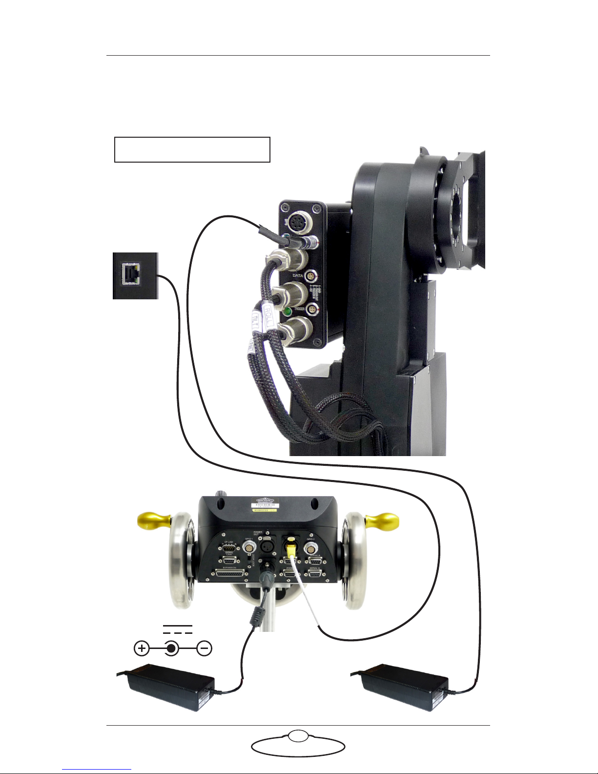
Quad-box example, for an SFH-50 head with stepper motors
24V 5A
#1 PAN
#2 TILT
#3 ROLL
E
THERNE
T
Rear
Front
Example:
MSA-20 Handwheels
POWER
18-36V
Attach the power cables last.
Quad-box
Quad-box
The head and
controller both use
the same type of
power supply brick.
Page 14
SFH-50 Quick Start Guide
10
Hint
If you use a dedicated controller that has a POWER OUT socket, you
should not use this socket to power the head if you are using
Ethernet to connect the head to the controller. If you do so then
powering up the controller will simultaneously power up the head,
and in this case powering up two Ethernet devices at the same time
on the same network can cause communication problems between
them.
Page 15
SFH-50 Quick Start Guide
11
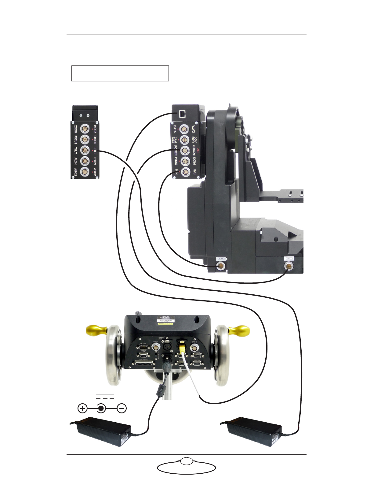
Ulti-box example, for an SFH-50 head with servo motors
24V 5A
PAN
E
THERNE
T
Rear
Front
Example:
MSA-20 Handwheels
POWER
Attach the power cables last.
Ulti-box
Ulti-box
TILT
TILT
PAN
The head and
controller both use
the same type of
power supply brick.
Page 16
SFH-50 Quick Start Guide
12
Your first session
Instructions for using the SFH-50 head with a specific controller, or with
Flair Motion Control Software running on a PC, are beyond the scope of
this manual. The first time you use the head you typically need to
perform the steps given below. Refer to the manual that came with your
controller or software for details.
1. Attach the power cables to the head and controller.
There is no power switch on the SFH-50 head; the power is
on whenever the 24-volt power supply is attached and live.
After you have attached the power cable, make sure the
relevant indicator on the head lights up.
Similarly, to turn off the head you simply remove the power cable.
All MRMC controllers and heads have robust electronics that are
designed to withstand the rigours of connection and disconnection
to live power cables.
2. Load the head.
The head does not retain any operating system when it is switched
off, so when you turn on the head you must load the head operating
system from the attached controller or PC.
For example to load the head from an LFP controller you press the
SELECT knob on the controller when prompted to do so. Different
head models and controller-head connection methods use different
operating systems, so be sure that the operating system that you load
from your controller is the correct one for your particular SFH-50
head model and connection method.
3. Set the control directions.
Hint
It is a good idea to attach the power cables last, after all the
other cables are in place.
It is also recommended that you power up the controller last,
after powering up the head if you are using Ethernet to connect
the head to the controller, as powering up two devices
simultaneously on the same Ethernet network can cause
communication problems.
Page 17

SFH-50 Quick Start Guide
13
In your controller or software you need to specify the directions of
the focus, zoom and joystick/handwheel controls for your particular
head, lens gearing attachments, and preference. For example, some
people prefer the camera to point upward when the joystick is pulled
back, while others prefer the opposite logic whereby pushing
forward (“up”) on the joystick targets the camera upward in the
scene.
For example to set the control directions on an LFP controller you
use the menu option SET DIRECTION. On the Mini MSA controller
you can use the same menu option or use the FWD and REV
hardware switches.
4. Zero the axes.
At the beginning of each session, right after loading the head, you
need to zero the axes. This defines a base position at which all head
positions and lens settings are set to zero (0) in the controller or
software. All limits, lens controls, preset positions, and moves that
are stored in the controller or software are measured relative to this
base position. The zero points themselves are not stored in the head
or lens when the power is off, so you need to define them at the start
of each session, by zeroing the axes.
For example to zero the axes with external Lens Control Motors you
first set the focus to infinity (), zoom to wide-angle (zoomed out
all the way), iris/aperture to wide open. You then use the
controller’s procedure for zeroing the head. For example to zero the
axes with the LFP controller you either go into film mode and use
the menu option HOME AXES > ALL AXES, or you use the controls
to point the camera head in the direction that you want to use as the
zero position for the head axes and use the menu option DIRECT
ZERO ALL
.
Page 18
SFH-50 Quick Start Guide
14
5. Set the limits.
In order to prevent damage to cables and other equipment, you can
set limits to the range of physical travel of the head movement and
lens controls.
For example to set the limits in the LFP controller you use the menu
option SET SOFT LIMITS.
Hint
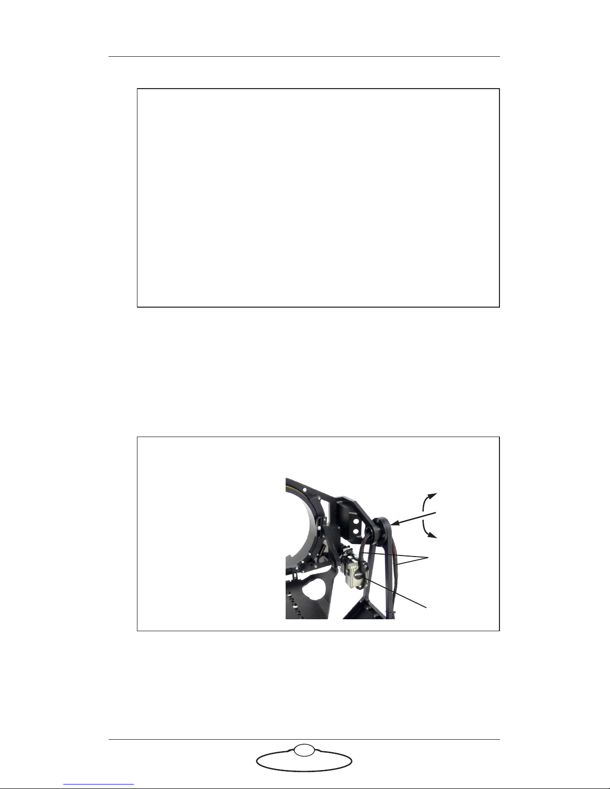
The homing facility on the SFH-50 head uses optical sensors
(with homing fins) on the Pan and Tilt axes. The optional Roll
facility uses a magnetic sensor. There are two magnets on the
Roll ring, so the Roll homing facility will work for both
over-slung and under-slung mount configurations. For either
configuration, note that the camera platform is not horizontal
in the Roll home position. This is intentional, as it makes the
homing procedure quick and directionally reliable when you
invoke the homing facility from a typical horizontal (or
near-horizontal) platform starting position, whether the camera
is over-slung or under-slung.
Hint
If your SFH-50 has a
Roll Ring, set a Tilt
limit within ±90° of a
horizontal platform in
order to avoid
damaging the Roll
motor cable which goes
through the hole in the
centre of the Tilt axle.
–90°
+90°
Roll motor
Roll motor
T
i
lt axle
cable
Page 19

SFH-50 Quick Start Guide
15
Subsequent sessions
After you have initially set up the system for your particular camera lens
and preferences, subsequent sessions take less time to set up, especially if
you have not disconnected control cables or moved sites. For subsequent
sessions at the same site you typically need to do the following at the start
of every session.
1. Attach the power cables to the head and controller.
2. Load the head.
3. Zero the axes.
If you have moved sites you will need to connect the control cables before
the power cables, and then set new limits after you have zeroed the axes.
Page 20
SFH-50 Quick Start Guide
16
SFH-50 Quick Start GuideSFH-50Quick Start Guide
Appendix 1 Troubleshooting
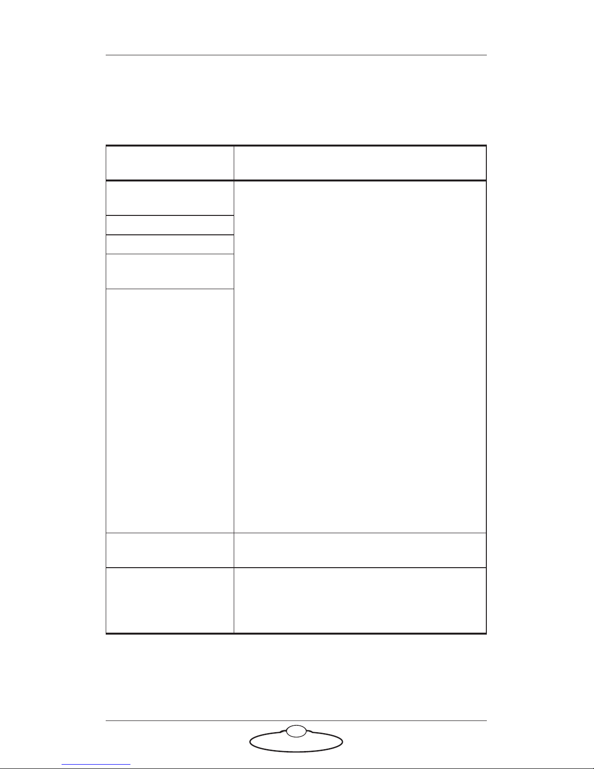
Typical symptoms, causes, and actions
Symptoms or message
on the controller
Cause and/or action
HEAD DID NOT
LOAD
The controller failed to load the operating
system into the head.
Check that all cables are connected, and all
devices have power.
Check the order in which the devices are
powering up. If two devices on the network try
to power up and initialise their Ethernet
connection at the same time, the devices can
conflict with each other on the network. Avoid
powering the head from the power output
socket on the controller, in order to avoid
powering them up simultaneously. Use an
independent power source for each, and power
up the controller after powering up the head.
If you have connected more than one head,
connected the MRMC system to another local
network, or moved the controller and head
between networks, check that correct LAN
addresses have been entered in the controller.
See Working with Local Area Networks on page
17.
HEAD NOT LOADED
LOAD FAIL
FAILED TO LOAD
HEAD
FAILED TO
INITIALIZE
ETHERNET
Controls move in the
wrong direction
Change the working direction of the controls
to your preference.
Limits are being
ignored or causing the
head to oscillate when
reached.
The axes have not been zeroed. You must do
this at the beginning of each session just after
you load the head.
Page 21

SFH-50 Quick Start Guide
17
Working with Local Area Networks
The controller and head communicate with each other through an
Ethernet Local Area Network (LAN). The controller and head are devices
on the network. Under certain circumstances you might need to change
the LAN settings of the devices so that the devices not only work together,
but do so when connected to another network. For example:
• If you install the controller as part of a multi-component
system.
• If you connect your MRMC equipment to a local network.
• If you move the equipment between networks.
• If you have customised the LAN settings in a head for one of
the above reasons and then sent the head back to MRMC for
servicing. The service might change the LAN settings back to
the factory defaults, and you will need to customise them again
when you get the head back.
Introduction to LAN addresses
Each device on an Ethernet network has a suite of three addresses:
• Internet Protocol (IP) address
• Subnet (SN) address
• Gateway (GW) address
Together, these addresses indicate the device’s identity and location on the
network. Each address is usually written as a group of four numbers
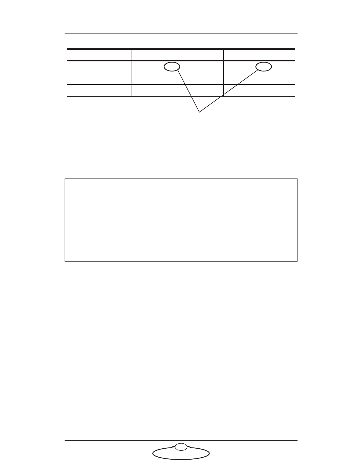
separated by periods. The factory default values used in MRMC
equipment are shown in the next table:
Page 22
SFH-50 Quick Start Guide
18
The LAN addresses of the controller and head are static. That is, they will
stay the same unless you explicitly change them.
Although a simple controller setup has only two devices on the network
(the controller and the head) there are potentially three IP addresses
involved:
1. The IP address of the controller itself. You don’t ordinarily need to
change this unless you are connecting it to a local network that
requires different settings.
2. The IP address that the controller looks for when it tries to find
and load the head on the network. This must match the next IP
address...
3. The actual IP address of the head. This is usually the IP address
shown in the above table unless it has been changed, or unless you
specified a different address when you ordered the head. In any case,
the factory-set IP address of a head is ordinarily printed on a sticker
on the head.
Hint
Most local networks use the SN and GW addresses shown in the
above table, so under ordinary circumstances you will only need to
be concerned with IP addresses. The rest of this section therefore
concentrates on IP addresses, but you might also need to inspect or
change the SN and GW addresses, depending on the structure of the
network that you are using to access the head.
MRMC Controller Head
IP address 192.168.1.235 192.168.1.236
SN address 255.255.255.0 255.255.255.0
GW address 192.168.1.1 192.168.1.1
On a given local network, the last group of
numbers in the IP address must be unique
for each device. All other numbers and
addresses must be identical.
Page 23
SFH-50 Quick Start Guide
19
You can usually inspect and change the first two IP address settings
directly on the controller, by accessing the LAN settings on the controller.
Once you have established a connection between the controller and the
head, you might be able to change the actual IP address of the head from
the controller. For details see the documentation that came with your
controller.
To find out the IP address of a head with an unknown history you must
connect it to a PC that has Flair Motion Control Software installed.
Details are in Managing LAN addresses with Flair on page 19.
Managing LAN addresses with Flair
The factory-set IP address of a head is printed on a sticker on the head.
If the IP address of a head has been changed to an unknown value so you
can’t load the head from the controller, you can find out the head’s IP
address by connecting the head to a Windows PC that has Flair Motion
Control Software installed on it, and use Flair to interrogate the head on
the network. You can also use Flair to change the IP, SN, and GW
addresses of the head if necessary.
1. Find a PC that has Flair Motion Control Software installed on it, or
install Flair on your own PC.
2. Attach the head to the PC with an Ethernet cable. You can use the
same Ethernet cable that was connecting the head to the controller.
3. Make sure the head has power.
4. Start Flair on the PC.
5. If you get any error messages, click on OK to close them.
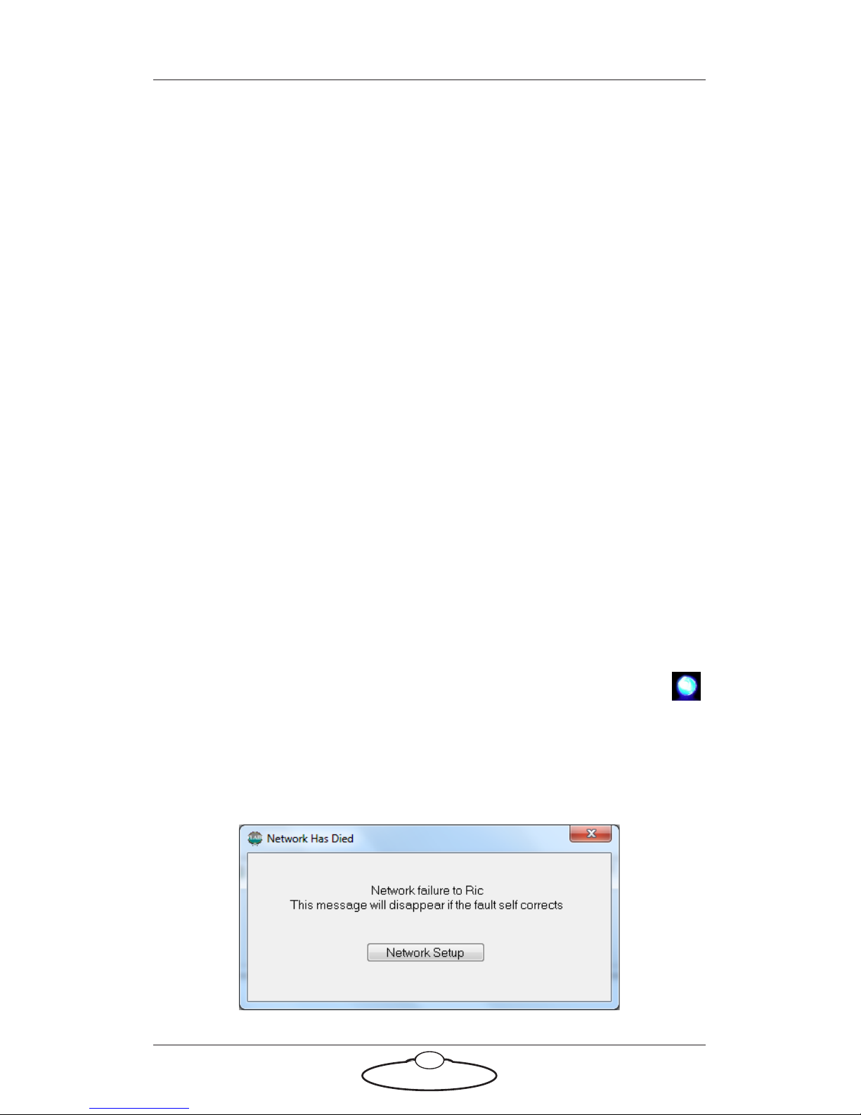
6. When you get a message about network failure, click on the
Network Setup button in the message:
Page 24
SFH-50 Quick Start Guide
20
or...
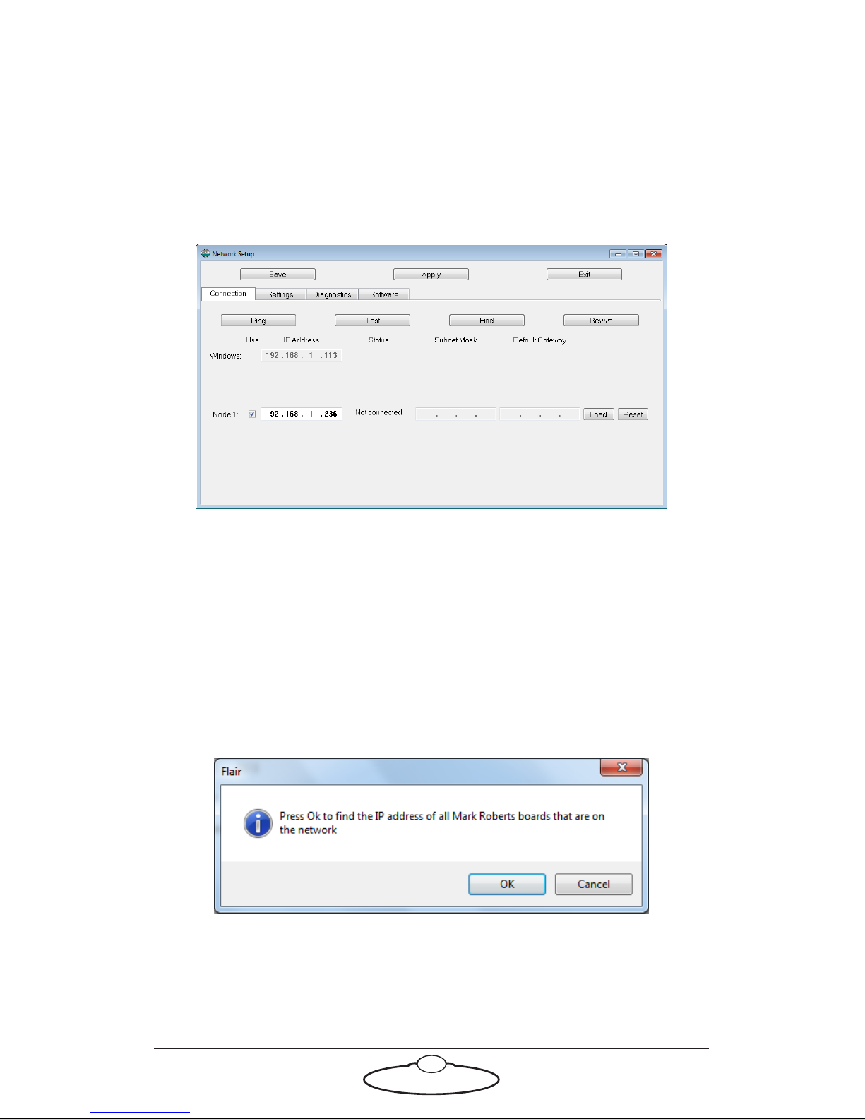
If the Flair installation already has a valid head connection on a
network then you might not get the network failure message. In this
case, start the Network Setup facility manually by choosing the
Setups > Network Setup menu option in Flair.
The Network Setup window, Connection tab, lists the Nodes (head
connections) that Flair is looking for, as defined in the
NetworkDirect.ini file. Any changes that you make and Save in the
Network Setup window are saved in the NetworkDirect.ini file. You
can also edit this file by using the menu option Help > View
Network .ini File. If Flair cannot find the head on the network at
the IP address shown then the node’s status is Not connected.
7. In the Network Setup window click on Find, then on OK in the
pop-up to confirm:
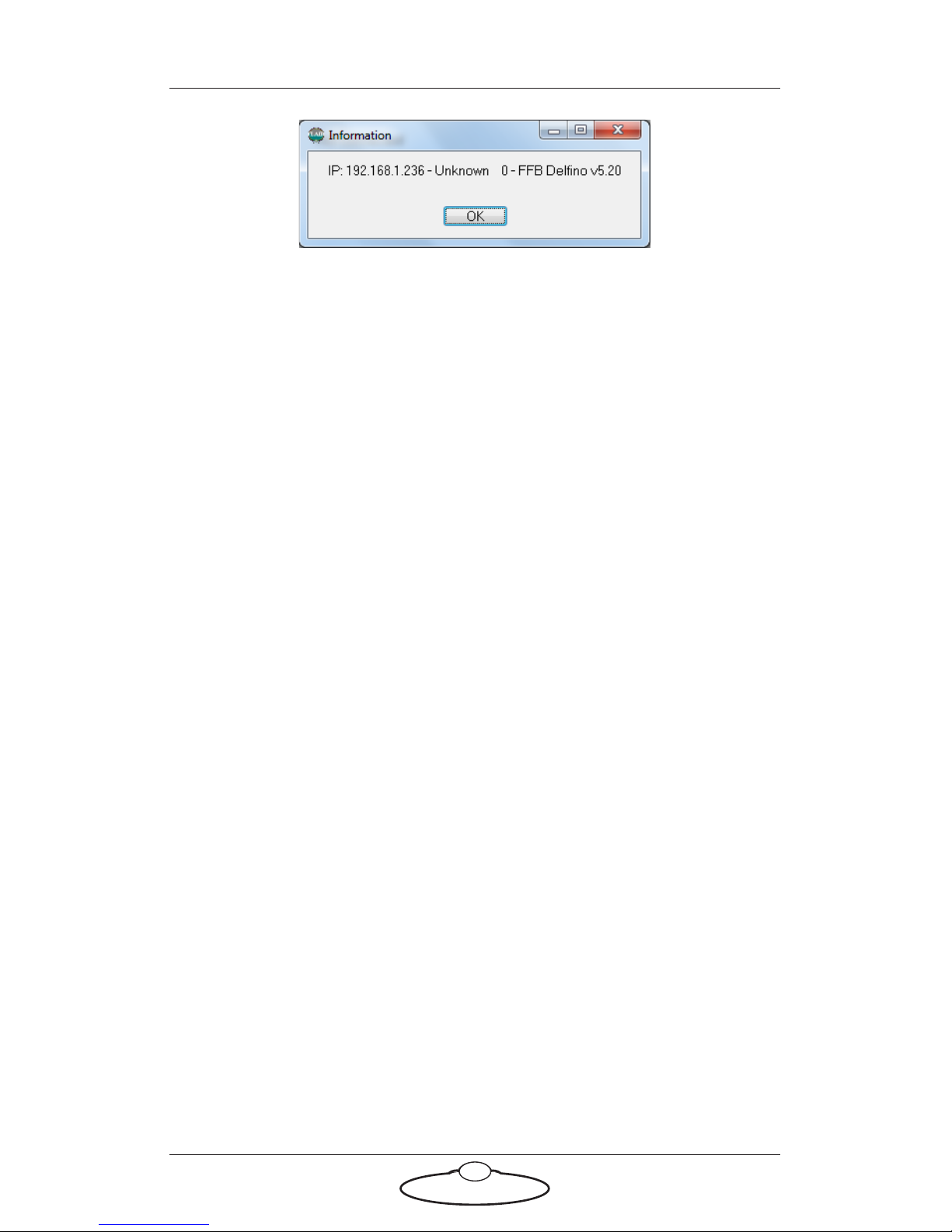
8. An Information pop-up displays information about the heads that
Flair has found on the network:
Page 25
SFH-50 Quick Start Guide
21
Make a note of the head’s IP address that is displayed in the pop-up;
for example 192.168.1.236.
9. If you want to use the head with Flair or change any of the head’s
LAN addresses, follow the substeps below:
9.1 Enter the head’s existing IP address (as shown in the
Information pop-up) into the Network Setup window and click
on Save.
9.2 Click on Load to reset and load the head.
Once Flair is connected to the head, any LAN address changes
that you make and Save in the Network Setup window will also
affect the LAN addresses stored in the head.
9.3 To change the IP address of the head, enter the new IP address
into the Network Setup window now and click on Save.
The Status temporarily changes to Not connected as Flair
changes the IP address in the head, then to Connected as Flair
reconnects with the head at its new IP address.
9.4 To inspect or change the SN or GW address of the head, click
on Find again. A pop-up shows the head’s three current LAN
addresses, and the Subnet Mask (SN) and Default Gateway
(GW) fields in the Network Setup window become editable.
Enter the new SN and GW addresses that you want to use and
click on Save.
10. Close the Network Setup window by clicking on Exit.
11. If you want to use a controller other than a Flair PC then you are
now done with the PC:
11.1 Close Flair by choosing the File > Quit menu option.
11.2 Disconnect the Ethernet cable from the PC, and re-attach it to
the controller, so the head and controller are now connected.
Page 26

SFH-50 Quick Start Guide
22
11.3 Tell the controller which IP address to look for by following the
procedures in the documentation that came with your
controller.
Page 27

SFH-50 Quick Start Guide
23
SFH-50 Quick Start GuideSFH-50Quick Start Guide
Appendix 2 SFH-50 Panel
Introduction to SFH-50 connections
Interface boxes
The SFH-50 uses a modular, replaceable interface box to manage the
connections between the camera, head, and controller. Your SFH-50 is
supplied with one of the following interface boxes:
Quad-box, for SFH-50 heads with stepper motors. See
Quad-box and Octo-box connector summary on page 24.
Octo-box, for SFH-50 heads with stepper motors. This box has
all the connectors of the Quad-box, plus four additional
stepper motor connectors and DataLink In/Out connectors.
See Quad-box and Octo-box connector summary on page 24.
Ulti-box, for SFH-50 heads with servo motors. See Ulti-box
connector summary on page 28.
Notes on head-controller communication methods
Three types of connections between the head and controller are in
common use in MRMC equipment:
Ethernet - This is the most modern preferred method, and uses
standard Ethernet plugs, cables, hubs, and protocols.
DataLink - This is an MRMC proprietary connection type
based on a modified form of Serial RS232. You can connect
several DataLink devices together in a daisy-chain. DataLink is
robust and dependable and is still the preferred connection
method in environments with high electrical interference that
can cause problems on Ethernet networks.
Serial RS232 - This is based on standard computer serial RS232
hardware and protocols.
Although many MRMC devices have built-in hardware for two or three of
the above connection methods, any controller that you use (such as the
MSA-20 Handwheels, LFP, or Mini MSA) must be programmed at the
factory for the connection method that you want to use.
Page 28
SFH-50 Quick Start Guide
24
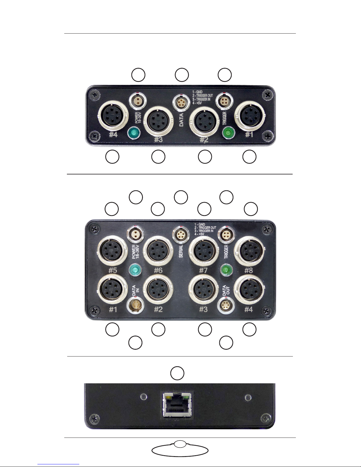
Quad-box and Octo-box connector summary
1234
9
10 11
Quad-box front
4321
5 6 7
Octo-box front:
8
9 10 11
12 13
14
Quad-box and Octo-box rear:
Page 29

SFH-50 Quick Start Guide
25
1-8. #1 - #8 connectors for the PAN (#1), TILT (#2), and ROLL (#3)
stepper motors in the head. The extra numbered connectors are for
auxiliary stepper motors. For pin-out information see Stepper motor
connector on page 26.
9. POWER 18-36V connector, for power input for the head. For
pin-out information see Power 18-36 Volts connector on page 26.
10. DATA (on a Quad-box) or SERIAL (on an Octo-box) connector.
This is a Serial RS232 connector, for updating the firmware in the
Quad-box or Octo-box. For pin-out information see Serial RS232
connector on page 26.
11. TRIGGER connector, for a bi-directional trigger signal between the
head and camera. For pin-out information see Trigger connector on
page 27.
12. DATA IN DataLink In (Up Link) connector for controlling the head
using a DataLink connection, as an alternative to an Ethernet
connection. You connect this to a device that is further up the
DataLink daisy-chain, such as one of the following:
The DATA OUT (or DOWN LINK) connector on a controller
such as the MSA-20 Handwheels or Large Format Panel (LFP).
The RIG/HEAD connector on an RT-12 interface box which is
in turn connected to a PC running Flair Motion Control
Software.
For pin-out information see Data In connector on page 27.
13. DATA OUT DataLink Out (Down Link) connector for connecting
additional devices on the DataLink network. This is not normally
used, as the Octo-box on the head is usually at the end of the
DataLink daisy-chain. For pin-out information see Data Out
connector on page 27.
14. ETHERNET RJ45 connector for controlling the head using an
Ethernet network connection, as an alternative to a DataLink
connection.
Page 30
SFH-50 Quick Start Guide
26
Quad-box and Octo-box connector pin-out information
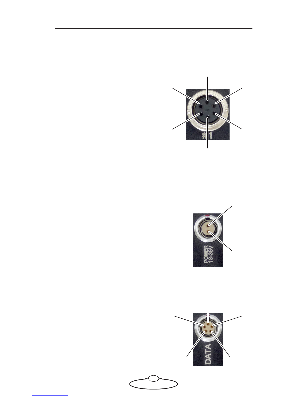
Stepper motor connector
This connector is used on the SFH-50
head with the stepper motor option.
The Quad-box and Octo-box have
connectors for Pan (#1), Tilt (#2), and
Roll (#3) motors, plus one or more
extra connectors for auxiliary stepper
motors.
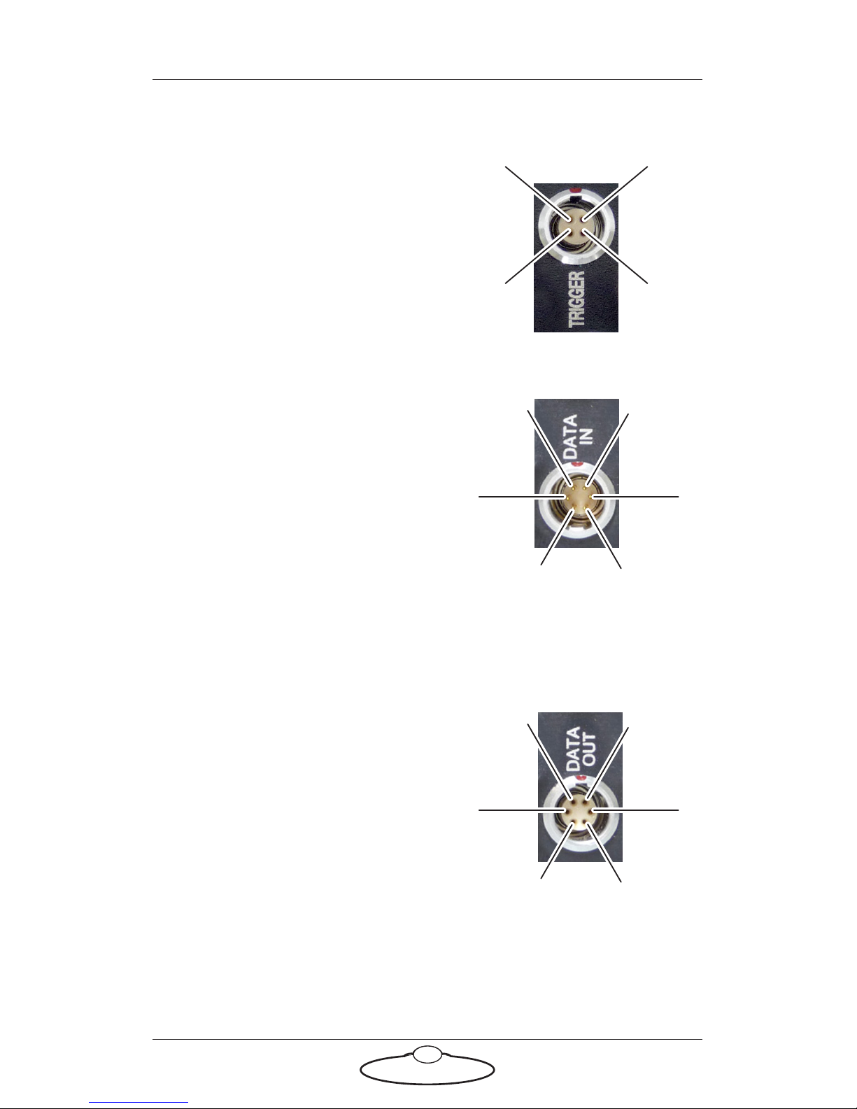
1. GND
2. 24V
3. 5V
4. Limit
5. Step
6. Direction
Power 18-36 Volts connector
Two-pin DC input for powering the
head. The head runs best on a 34-Volt
power supply.
1. GND
2. +24V
Serial RS232 connector
This is a 5-pin Serial RS232 connector.
For usage see page 25.
1. Boot select
2. Tx (out)
3. Rx (in)
4. 5V
5. GND
5
6
1
3
2
4
2
1
4
5
3
2
1
Page 31
SFH-50 Quick Start Guide
27
Trigger connector
Trigger connection with Trigger Out
and Trigger In connections.
1. GND
2. Trigger Out
3. Trigger In
4. +5V
Data In connector
This is a 6-pin male DataLink In (Up
Link) connector for connection to a
DataLink device higher up in the
DataLink daisy-chain. For usage see
page 25.
1. Watchdog–
2. Link1Out–
3. Link1Out+
4. Link1In–
5. Link1In+
6. Watchdog+
Data Out connector
This is a six-pin female DataLink Out
(Down Link) connector for connection
to a head. For usage see page 25.
1. Watchdog–
2. Link1Out–
3. Link1Out+
4. Link1In–
5. Link1In+
6. Watchdog+
3
4
2
1
2
1
6
4
5
3
5
6
1
3
2
4
Page 32
SFH-50 Quick Start Guide
28
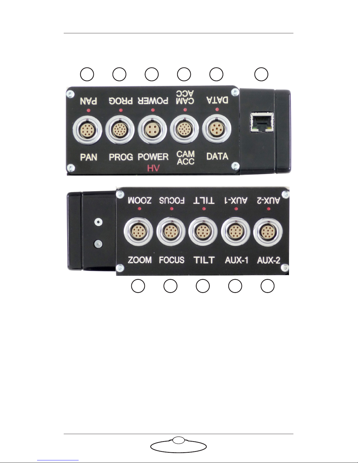
Ulti-box connector summary
1. PAN connector for the Pan servo motor on the head. For pin-out
information see Servo motor connector on page 30.
2. PROG serial connector for connection to a controller using a Serial
RS232 connection (as an alternative to an Ethernet or DataLink
connection), and for updating the firmware in the Ulti-box. For
pin-out information see Program serial connector on page 30.
3. POWER DC input for the head. The standard unit uses a power
input of 24-36 Volts. The high-power variant (marked HV, for High
Voltage) uses 24-48 Volts. For pin-out information see Power
connector on page 31.
1 3 4 5 62
7 8 9 10 11
Page 33

SFH-50 Quick Start Guide
29
4. CAM ACC Camera Accessory input/output connector. It has pins for
three stepper motors, two serial lens controls, two trigger in
controls, and two trigger out controls. For pin-out information see
Camera Accessory connector on page 31.
5. DATA DataLink In (Up Link) connector for controlling the head
using a DataLink connection, as an alternative to an Ethernet or
Serial RS232 connection. You connect this to a device that is further
up the DataLink daisy-chain, such as one of the following:
The DATA OUT (or DOWN LINK) connector on a controller
such as the MSA-20 Handwheels or Large Format Panel (LFP).
The RIG/HEAD connector on an RT-12 interface box which is
in turn connected to a PC running Flair Motion Control
Software.
Note that because there is no DataLink Out connector on the
Ulti-box, the Ulti-box must be connected at the end of the DataLink
daisy-chain rather than the middle. For pin-out information see
Data In connector on page 32.
6. ETHERNET RJ45 connector for controlling the head using an
Ethernet network connection, as an alternative to a DataLink or
Serial RS232 connection.
7, 8. ZOOM, FOCUS connectors for external servo Lens Control Motors
(LCMs). For pin-out information see Servo motor connector on page
30.
9. TILT connector for the Tilt servo motor on the head. For pin-out
information see Servo motor connector on page 30.
10, 11. AUX-1, AUX-2 connectors for control of auxiliary servo motors.
For pin-out information see Servo motor connector on page 30.
Page 34
SFH-50 Quick Start Guide
30
Ulti-box connector pin-out information
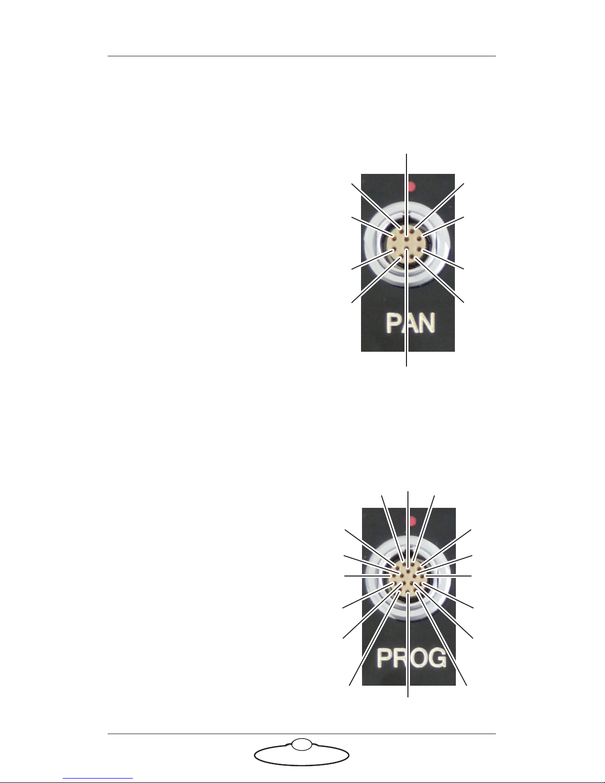
Servo motor connector
This type of connector is used for six
servo motor connectors on the Ulti-box:
Pan, Zoom, Focus, Tilt, Aux-1, Aux-2.
1. DATUM
2. A+
3. B+
4. Z+
5. N/C
6. MOTOR_B
7. MOTOR_A
8. LIMIT
9. +5V
10. GND
Program serial connector
Serial connector for connection to a controller using a Serial RS232
connection, and for updating the firmware in the Ulti-box.
1. SerialTxA
2. SerialRxA
3. +5V
4. FGPIO
5. DSP_TRSTN
6. TCK
7. TMS
8. DSP_TDI
9. DSP_TDO
10. DSP_EMU0
11. DSP_EMU1
12. FPGA_TDI
13. FPGA_TDO
14. BOOT_SEL
15. +3.3V
16. GND
2
1
4
3
7
8
5
6
9
10
1
2
3
4
5
7
15
8
9
10
11
13
6
16
12
14
Page 35
SFH-50 Quick Start Guide
31
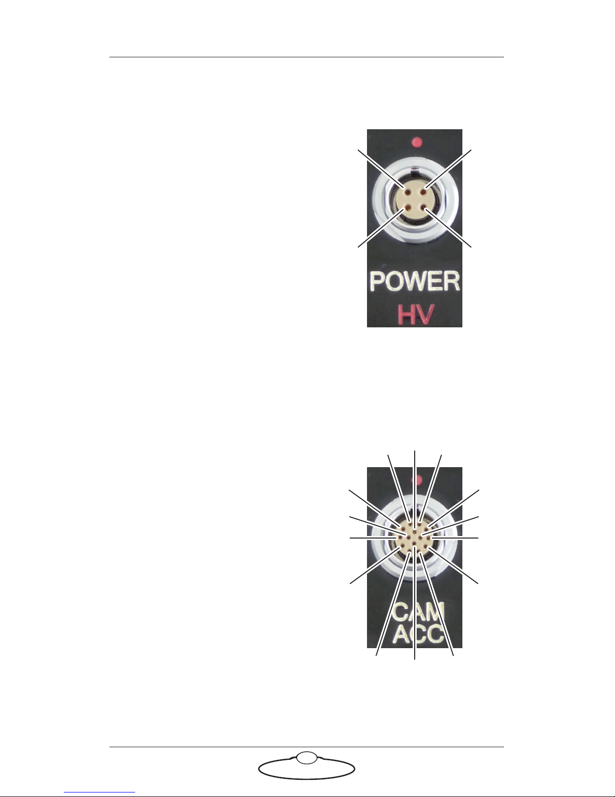
Power connector
The power input connector for the Ulti-box. For usage see page 28.
1. GND
2. GND
3. +35V
4. +35V
Camera Accessory connector
This is a multi-purpose camera accessory connector with connections for
three stepper motors, two serial lens controls, two trigger in controls, and
two trigger out controls.
1. Step1
2. Gp2In (Trigger In 2)
3. Step2
4. SerialTxB serial lens control
5. Step3
6. SerialRxB serial lens control
7. Dir3
8. GND
9. +5V
10. Gp1In (Trigger In 1)
11. Dir1
12. Dir2
13. Gp2Out (Trigger Out 2)
14. Gp1Out (Trigger Out 1)
3
4
2
1
1
2
3
4
5
6
7
8
9
10
11
12
13
14
Page 36
SFH-50 Quick Start Guide
32
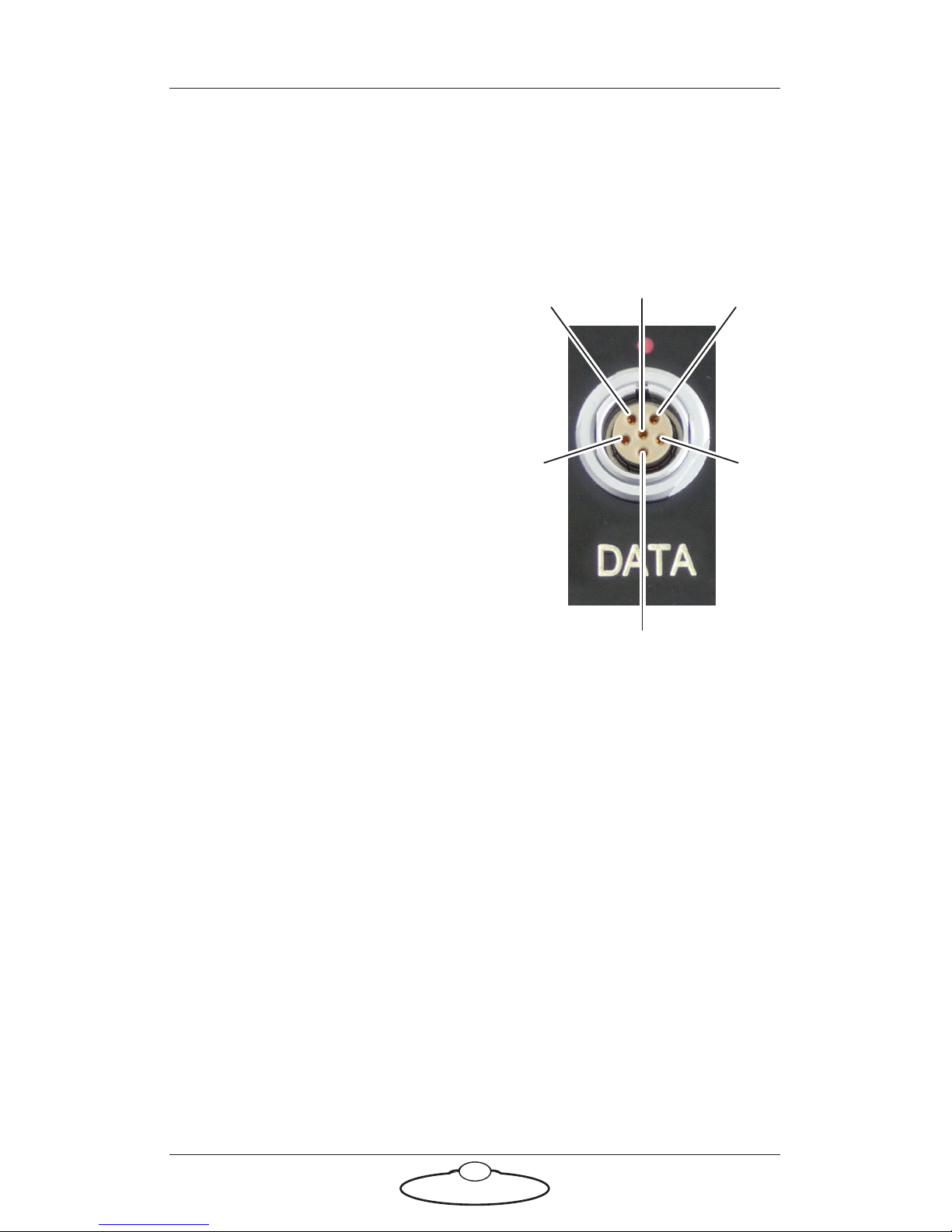
Data In connector
This is a DataLink In connector for connection to a controller using a
DataLink connection. DataLink In (Up Link) connector for connection to
a DataLink device higher up in the DataLink daisy-chain. For usage see.
page 29.
1. Watchdog–
2. Link1Out–
3. Link1Out+
4. Link1In–
5. Link1In+
6. Watchdog+
5
4
1
2
3
6
Page 37
SFH-50 Quick Start Guide
33
SFH-50 Quick Start GuideSFH-50Quick Start Guide
Appendix 3 Specifications
Weight: 6.5Kg to 11Kg, depending on options
Power requirements: 18-36 Volts DC
Temperature range: 0-45 °C (32-113 °F)
Humidity tolerance: 20% to 85% relative humidity, non-condensing
Camera payload: 13Kg
Maximum speed: 30°/sec to 100°/sec, depending on options
Maximum acceleration: 100°/sec2
Accuracy of playback (angular resolution): Better than 0.0001°
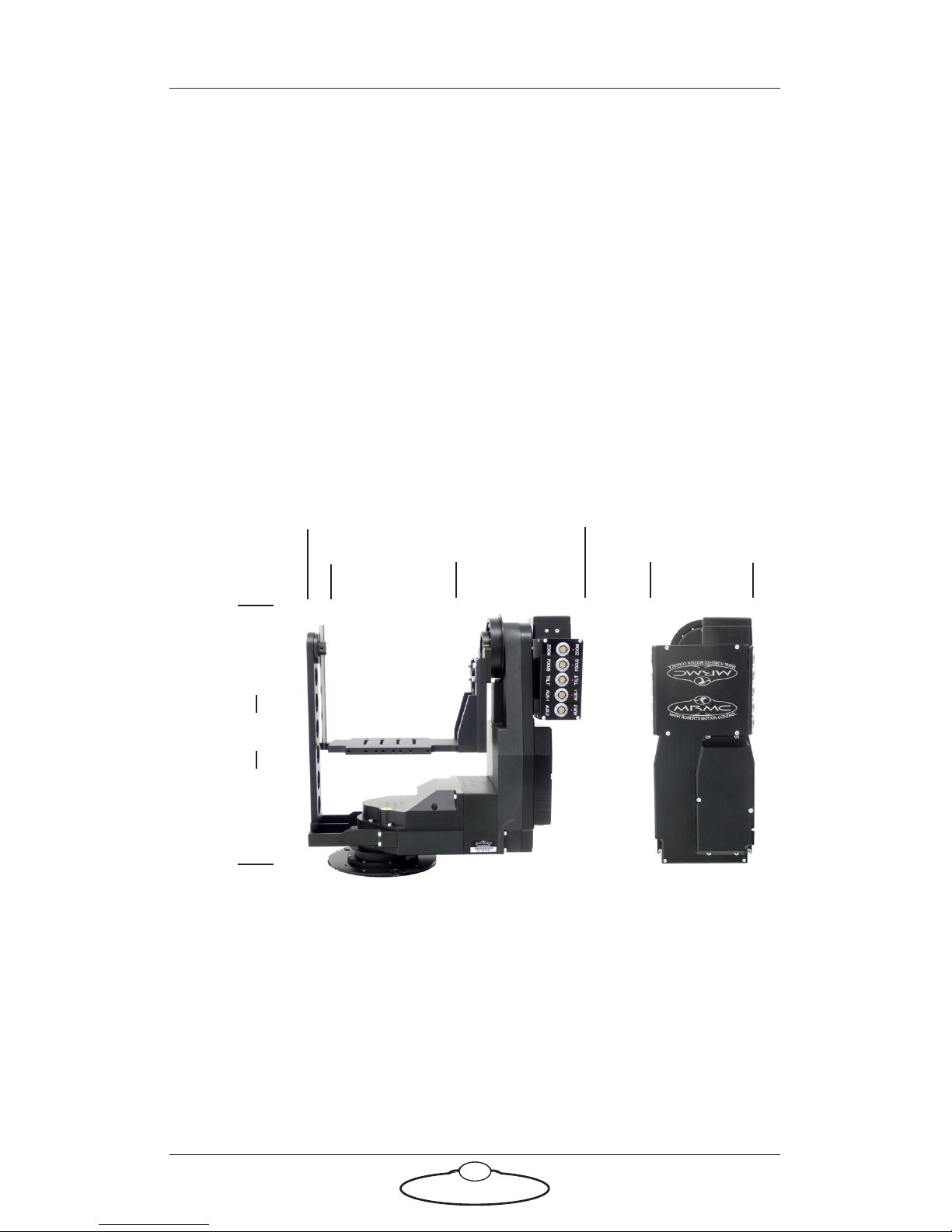
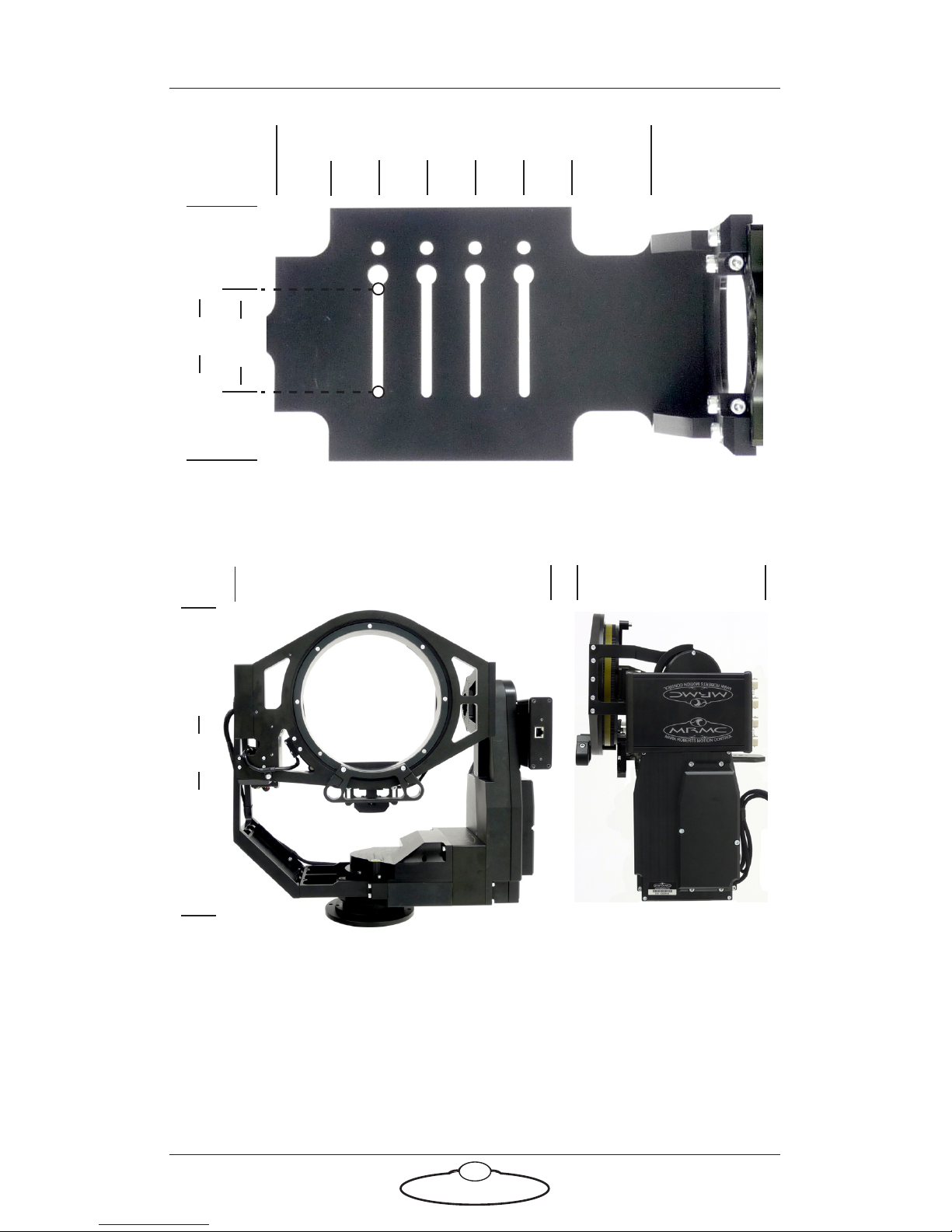
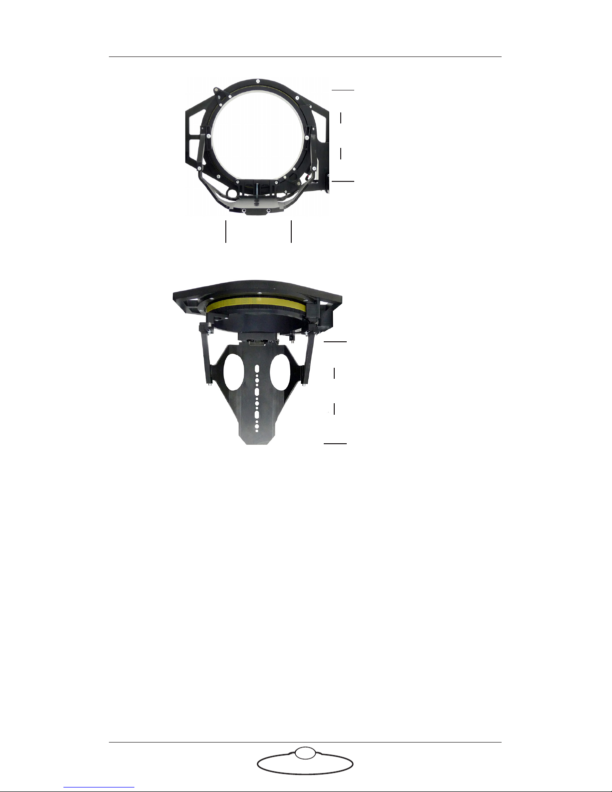
Dimensions are shown below. All measurements are in mm.
SFH-50 with Support Arm:
— 143 —
— 373 —
358
— 192 —
Page 38
SFH-50 Quick Start Guide
34
SFH-50 with Roll Ring:
130
53
- 25 - - 25 - – 40 –
— 192 —
- 25 - - 25 -- 27 -
- 25 -
max
— 305 —
— 480 —
455
Page 39
SFH-50 Quick Start Guide
35
— 188 —
215
116
Roll Ring
inner diameter
Platform width
Roll Ring
platform length
Page 40
Mark Roberts Motion Control Ltd.
Unit 3, South East Studios, Blindley Heath, Surrey RH7 6JP
United Kingdom
Telephone: +44 (0) 1342 838000
www.mrmoco.com
 Loading...