

Page 1
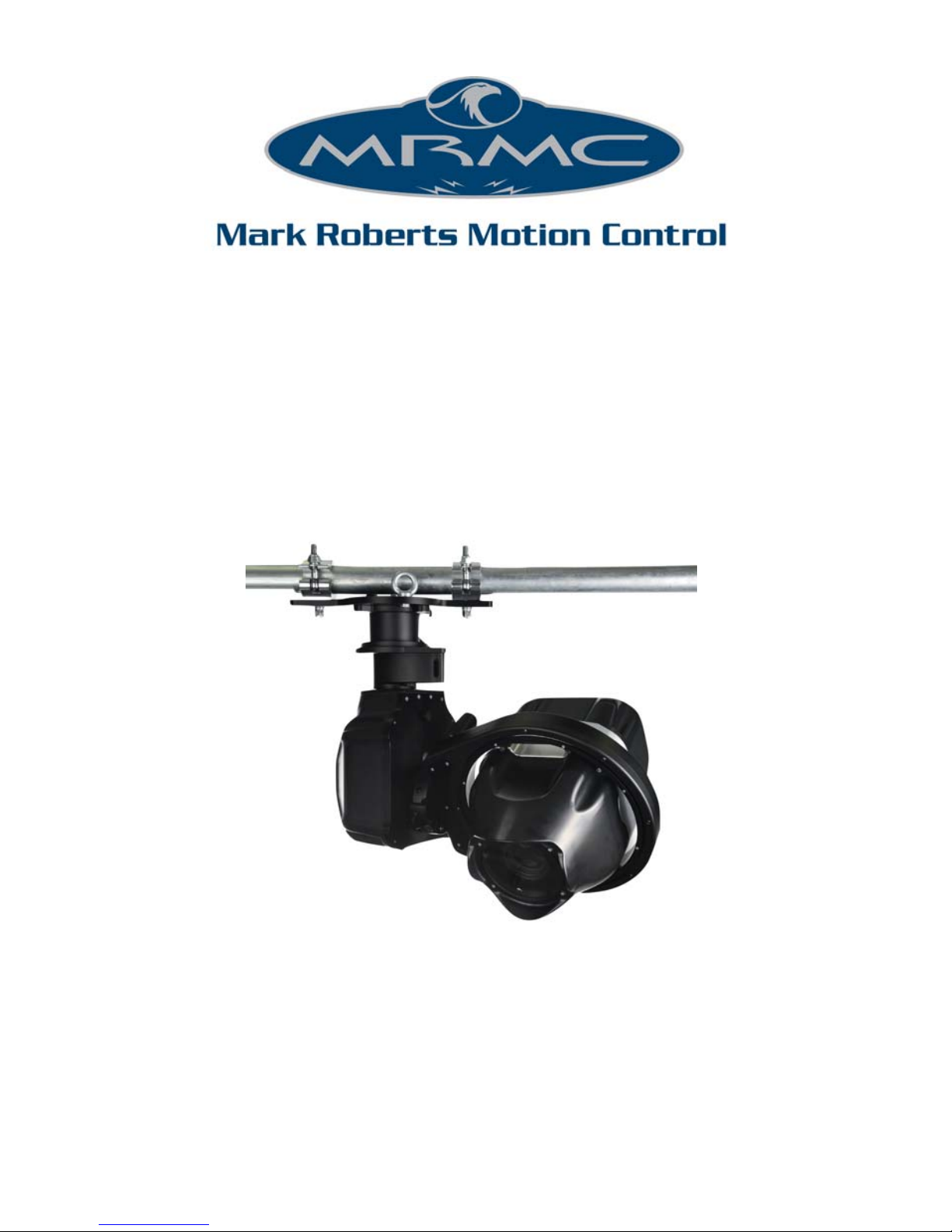
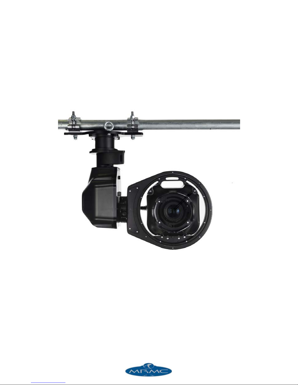
Robotic Pod
(Stadium)
Quick Start Guide
Part number: MRMC-1464-00
Product code: MRMC-1292-C
Page 2

ii
Robotic Pod (Stadium) Quick Start Guide
Part number: MRMC-1464-00
Product code: MRMC-1292-C
© 2017 Mark Roberts Motion Control Ltd. All rights reserved.
No part of this publication may be reproduced, transmitted, or translated
by any means — graphical, electronic, or mechanical — including
photocopying, recording, taping, or storage in an information retrieval
system, without the express written permission of Mark Roberts Motion
Control.
Although every care has been taken to ensure that the information in this
document is accurate and up to date, Mark Roberts Motion Control
continuously strives to improve their products and may make changes to
the hardware, firmware, and software described in this document. Mark
Roberts Motion Control therefore cannot be held responsible for any
error or omission in this document.
All product names mentioned herein are the trademarks or registered
trademarks of their respective owners.
Contact information
Mark Roberts Motion Control Ltd.
Unit 3, South East Studios
Blindley Heath
Surrey
RH7 6JP
United Kingdom
Telephone: +44 (0) 1342 838000
E-mail: [email protected] (sales and general enquiries)
[email protected] (customer support)
We b: www.mrmoco.com
www.mrmocorentals.com
Page 3

iii
Robotic Pod (Stadium) Quick Start GuideRobotic PodQuick Start Guide
Contents
Chapter 1 Quick Start..................................................................... 1
Important safety instructions ...............................................1
Power and connections................................................ 1
General care................................................................... 1
Location .........................................................................2
Intellectual property..................................................... 2
Overview .................................................................................3
Setting up the hardware ........................................................3
Connecting the cables ...........................................................9
Setting up the Robotic Pod System using the MHC
software .................................................................................11
Home Zeroing .....................................................................12
Changing system configuration and network settings....13
Launching MHC as Admin .......................................13
Network setup ......................................................................15
Adding Pods ................................................................15
Adding Pods by using FIND............................15
Adding Pods manually......................................16
Changing a Pod’s name..............................................16
Assigning Pods to user(s) ..........................................16
Removing a Pod ..........................................................17
Editing network settings on the Pod........................17
Adding users.........................................................................17
Changing the Server IP address................................18
Logging in as a User ...................................................18
TDCGraphics software ..............................................19
Port tabs .......................................................................20
Polycam system ....................................................................22
Polycam settings..........................................................22
Tracking data............................................................... 26
Page 4

Robotic Pod Quick Start Guide
iv
Lens tab .................................................................................27
Linearise Zoom button.....................................28
Importing lens settings.....................................28
Exporting lens settings .....................................28
Infinity offset......................................................29
Lens Focal Length .............................................29
Sensor Width and Height.................................30
Use Pan to Calibrate FOV................................30
Focus calibration ...............................................30
Zoom linearisation............................................31
Tools tab.......................................................................32
EXPORT ROBOT SETTINGS.........................32
Reset Robot ........................................................33
IMPORT ROBOT SETTINGS.........................34
Reset Camera ....................................................34
Camera Direct Connection Toggle ................34
TenPin Init .........................................................34
Subsequent sessions .............................................................34
Appendix 1 Troubleshooting...........................................................36
Typical symptoms, causes, and actions.............................36
Appendix 2 Pod connectors ............................................................ 39
Connector pin-outs..............................................................39
Panel mount connector..............................................39
Panel mount connector..............................................40
Power In connector ....................................................40
Mains In connector ....................................................41
SDI Out Connector ....................................................41
Appendix 3 Specifications............................................................... 43
Page 5

1
Robotic Pod (Stadium) Quick Start GuideRobotic Pod (Stadium) Quick Start Guide
Chapter 1 Quick Start
Important safety instructions
To ensure the best from the product, please read this manual carefully.
Keep it in a safe place for future reference.
To reduce the risk of electric shock, do not remove the cover from the
unit. No user serviceable parts inside. Refer servicing to qualified
personnel.
Power and connections
This unit must be connected to a mains socket outlet with a
protective earth connection.
This unit is not disconnected from the AC power source as
long as it is connected to the wall outlet.
When not using the unit for a long period of time, ensure that
the AC power cord is disconnected from the wall outlet.
The AC wall outlet should be installed near to the unit and be
easily accessible.
Do not plug in or attempt to operate an obviously damaged
unit.
General care
Do not force switches or external connections.
When moving the unit, disconnect the mains cable and then
disconnect the long umbilical cable.
Do not attempt to clean the unit with chemical solvents or
aerosol cleaners, as this may damage the unit. Use a clean dry
cloth.
Do not use around flammable gas. All electrical equipment can
generate sparks that can ignite flammable gas.
Keep away from pets and children. The head has powerful
motors that can pinch, so take care not to get your hands
trapped in the head or cabling.
Page 6

Robotic Pod (Stadium) Quick Start Guide
2
Keep cables tidy. Use cable ties to keep them out of harm’s way.
If you have a head with slip rings then make use of them; avoid
running any cables between the base and the rotating head or
camera.
Location
Installation of this unit should be away from sources of excessive heat,
vibration, and dust.
Intellectual property
This product includes confidential and/or trade secret property.
Therefore, you may not copy, modify, adapt, translate, distribute, reverse
engineer, or decompile contents thereof.
Page 7
Robotic Pod (Stadium) Quick Start Guide
3
Overview
Thank you for using the robotic Pod camera head from Mark Roberts
Motion Control (MRMC). The Pod head is designed for reliable day-in,
day-out use in professional studio and Outside Broadcast environments.
The versatility of the Pod head makes it suitable for live action, stills, and
time-lapse applications.
You can use the Ethernet connection on the Pod head to connect directly
to a PC running Multi-Head Controller (MHC) software
Setting up the hardware
1. Mount the Pan Tilt Arm (PTA) onto a heavy-duty scaffolding pole
by securing the PTA to the pole using the two scaffolding clamps.
Ensure the nuts on the clamps are tight and the arm cannot twist on
the scaffolding plate.
Note
Ensure the mounting bar can take the weight without stress and that
the space on the bar is free to allow full movement of the pod when
panning without hitting any obstacles. The maximum weight of the
PTA system is 30kg but due to motion and, if mounted outdoors
possible high winds, the bar should be able to support at least 100kg.
The torque setting of the screws in the scaffolding clamps is
159.1Nm. Always ensure there is enough thread going through the
nyloc.
Page 8

Nuts
PTA underslung
PTA overslung
If the head is going to be
used for target tracking,
then ensure that the PTA
is perfectly levelled to the
ground using a spirit level.
Robotic Pod (Stadium) Quick Start Guide
4
Page 9

Robotic Pod (Stadium) Quick Start Guide
5
2. Attach the safety cable around the bar, through at least one eyelet,
and through the pan safety hole (near the connector socket).
Remove any excess slack by making extra loops around the bar.
Then join with a carabiner and screw the carabiner shut.
Pan safety hole
Eyelet
Wind any excess
cable around
scaffolding pole
Carabiner screwed shu
t
Note
Safety cables should be wound up to keep them short:
In the event of a fall, the falling item has less opportunity
to get speed before the cable catches it.
This prevents them catching on any moving parts.
Page 10

Robotic Pod (Stadium) Quick Start Guide
6
3. Attach the roll ring to the arm by sliding the roll wedge into the side
plate and ensure the safety catch locks into place —preventing the
roll ring to be detached again. Then tighten the two captive screws
to firmly secure the roll.
Safety catch
Once the roll ring is
attached to the arm, safety
catch locks into place
Roll motor
Do not use the
roll motor as a
carrying handle.
Tighten the screws
using 4mm allen key.
The torque setting of
the screws is 11.2Nm.
Do not touch the
contacts on the roll
ring or the PTA.
Page 11

Robotic Pod (Stadium) Quick Start Guide
7
4. Attach the pod to the roll ring by sliding the pod front into the roll
ring from rear. Note the pod has a wedge on its bottom that will
slide into a plate on the roll ring. You can use the roll ring to help
support the weight of the pod while mounting by pointing the pod
downwards.
5. Tighten the three screws on roll ring to secure the Pod into the head.
The Pod is not secure
until it is screwed in.
The torque setting of
the screws is 11.2Nm.
Page 12

Robotic Pod (Stadium) Quick Start Guide
8
6. Attach the safety cable between the pod handle and the roll safety
hole. Ensure you do not tie it around the roll ring. Wind up any
excess cable by looping further through the holes. Screw closed the
carabiner.
Pod handle
Roll safety
handle
Ensure that you do
not tie the safety
cable around the roll
ring.
Page 13
Robotic Pod (Stadium) Quick Start Guide
9
Connecting the cables
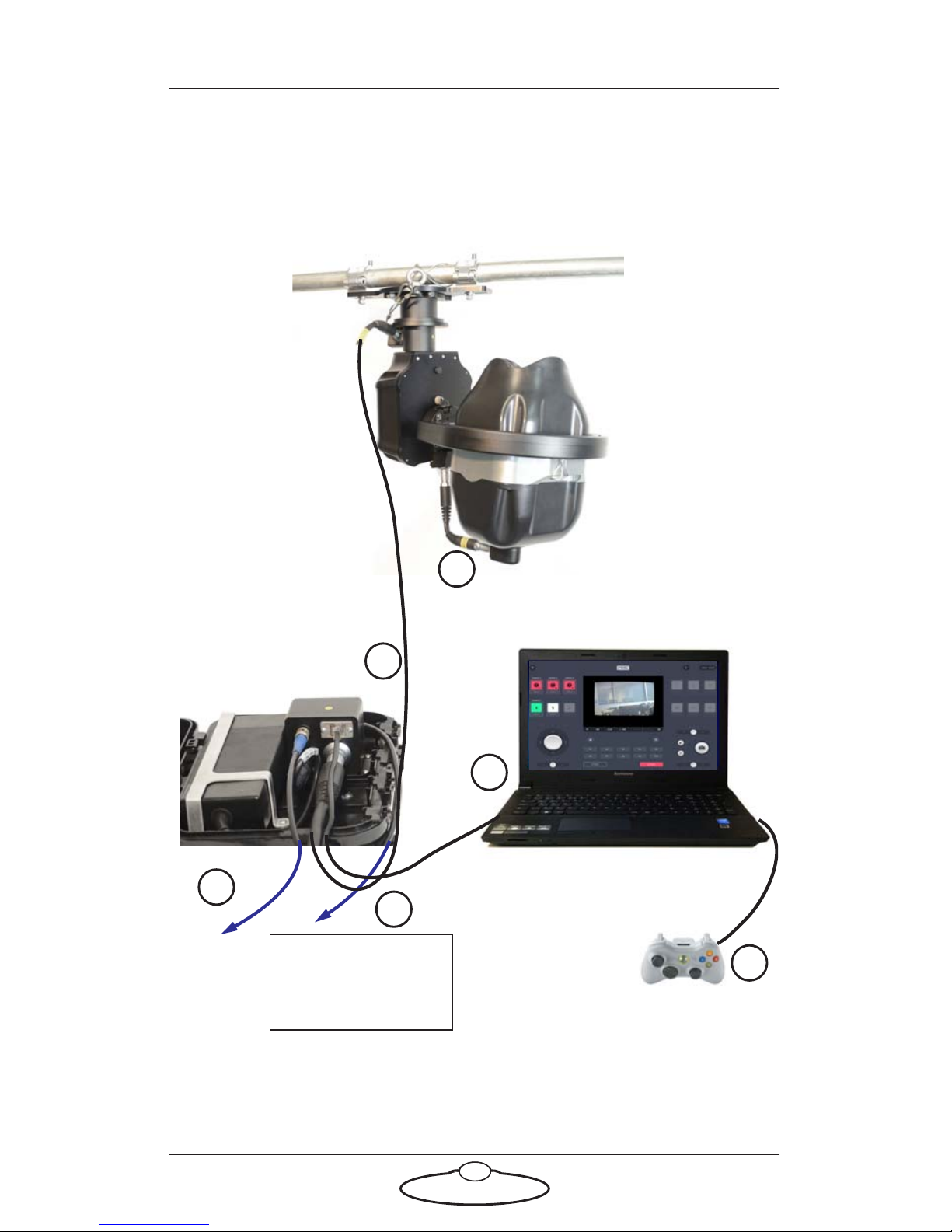
Attach the power cables ensuring each connector is fully secured into the
socket and that the cable or connector is not caught in any moving part.
C
ommunications / PO
WER 24V
PC running MHC
Software
ETHERNET
SDI OUT
From Mains
100-240V 447-63Hz
1.6A Max
1
2
3
4
USB joystick, such as an XBox
joystick or MRMC Joystick
Controller
5
6
USB
Break-out box
Page 14

Robotic Pod (Stadium) Quick Start Guide
10
1. Connect the short umbilical cable to the power connectors in the
PTA and the Pod. Ensure the red markers on the socket and the plug
align.
2. Connect one end of the long umbilical cable to the
PTA-1 and the other to the power supply socket in the
break-out box. Ensure the red markers on the socket
and the plug align.
3. Connect one end of the network cable to the Ethernet connector in
the junction box and the other to the PC. If your setup contains
multiple heads connected via Ethernet, then the network cable
would connect to a network switch, which in turn would be
connected to the PC.
4. Connect the SDI Out connector to a video output device using a
standard coaxial cable.
5. Optionally, connect the USB port on the PC to a joystick, such as an
Xbox joystick or a MRMC Joystick Controller. This device gives you
a precise and real-time control of the camera direction and
functions. You can use the MHC screen to control the camera
instead if you omit a joystick.
6. Finally, connect the mains cable to the power supply.
Page 15
Robotic Pod (Stadium) Quick Start Guide
11
Setting up the Robotic Pod System using the MHC
software
To control and use the Pods, you need to connect them to the network
that has the PC running the MHC server software. You can choose to
assign the Pods to specific users using MHC server. Then, each user can
use the MHC client application to control the Pod assigned to them
1. Attach the cables to the Pod and PC, as described in the previous
section.
2. There is no power switch on the Pod; it is
powered on whenever the mains supply is
attached and live. After you have attached the
power cable, make sure the power indicator
LED on the Pod lights up.
3. Similarly, to turn off the Pod you simply
remove the power cable.
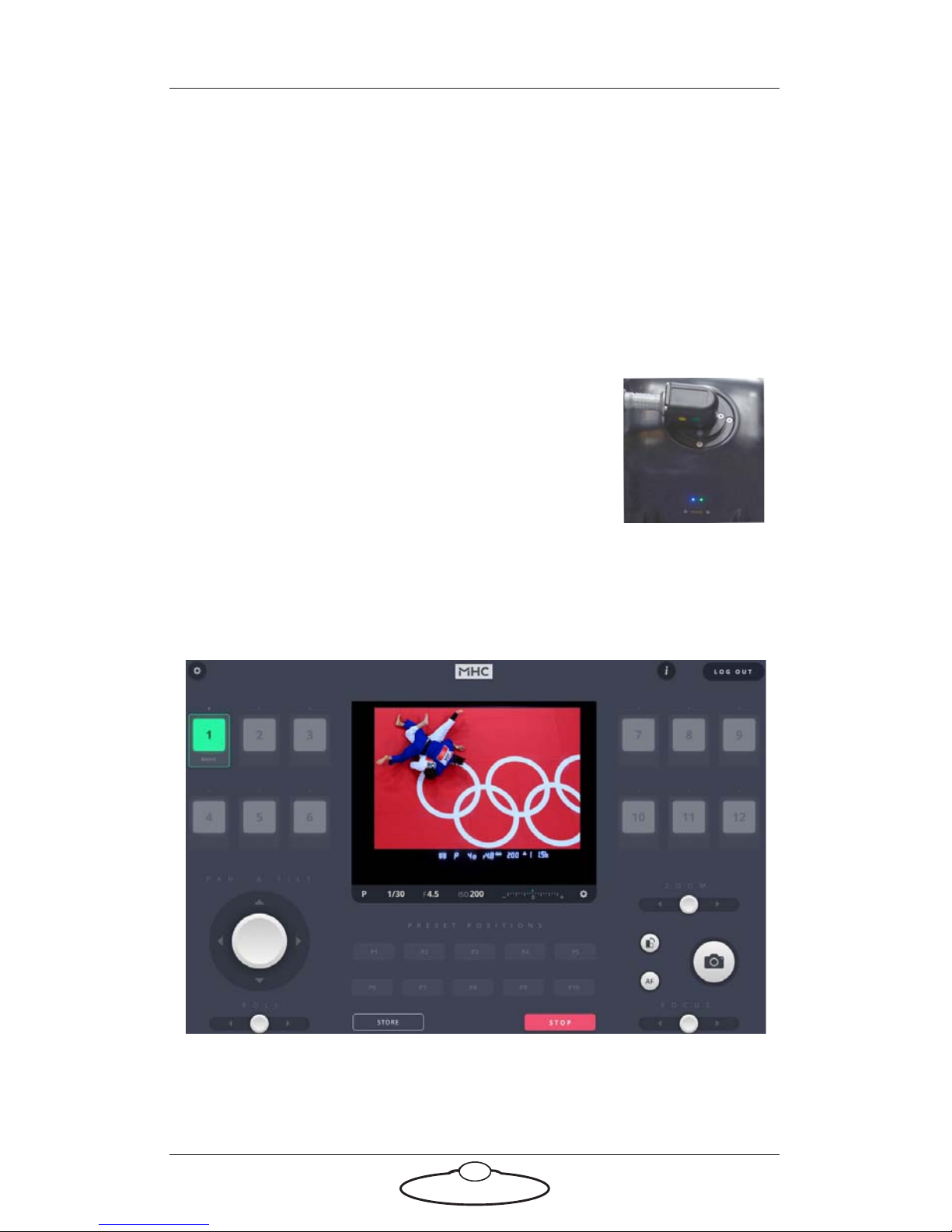
4. Power up the PC. Both the MHC Server and Client applications are
started. The MHC Main page appears.
Observe that the cabled Pod appears as a white or green icon to
show that it is connected over the network.
Page 16
Robotic Pod (Stadium) Quick Start Guide
12
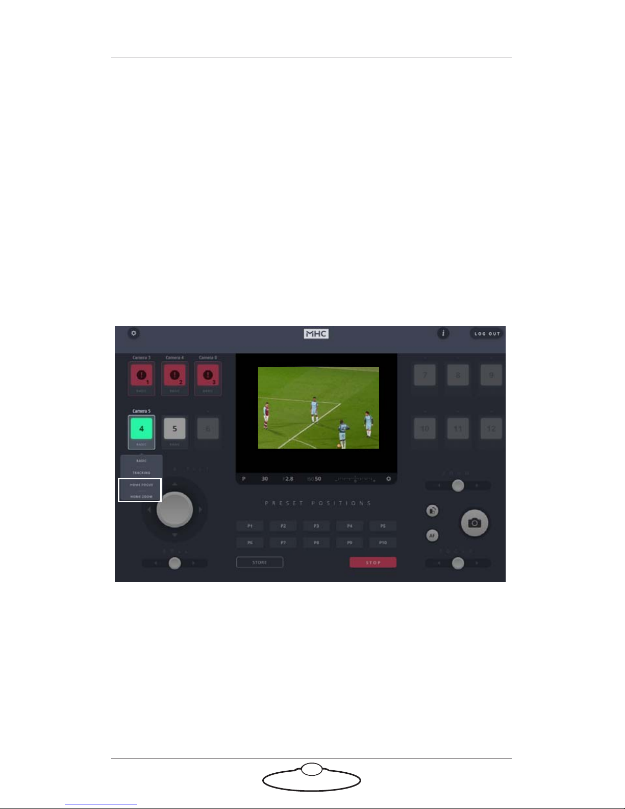
5. Clicking/tapping the Pod icon enables the Pod and changes the icon
to green showing it is selected for control from the Main page.
Observe that the un-cabled Pods appear as red icons.
Cable together and power up the remaining Pods. They will appear on
MHC connected, as white icons.
Home Zeroing
Pan, Tilt and Roll axes in Pods are absolute encoders making Homing an
automatic function. Therefore these axes do not need to be Homed by the
User. However, the lens axes Zoom and Focus do need to be Homed. To
home the axes, left-click and hold the Pod head icon and select HOME
FOCUS or HOME ZOOM.
Page 17
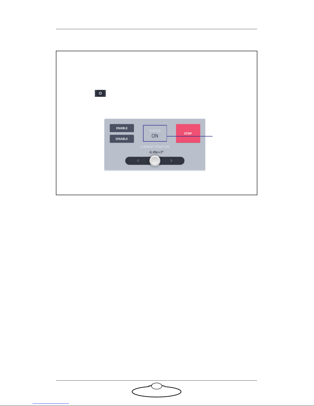
Note
The focus and zoom axes must be homed individually. If an error
occurs after homing, do the following:
1. In the > Robot > Axes tab, check that the Status of the axis
is ON in the grey box. If it is not, click the ENABLE button to
turn it on.
Status should
be ON
2. Click/tap the HOME button to home the selected axis.
Robotic Pod (Stadium) Quick Start Guide
13
Changing system configuration and network
settings
Launching MHC as Admin
To change any network setting, you need to be logged in to the MHC
Client as the Administrator.
1. Log out of the User login.
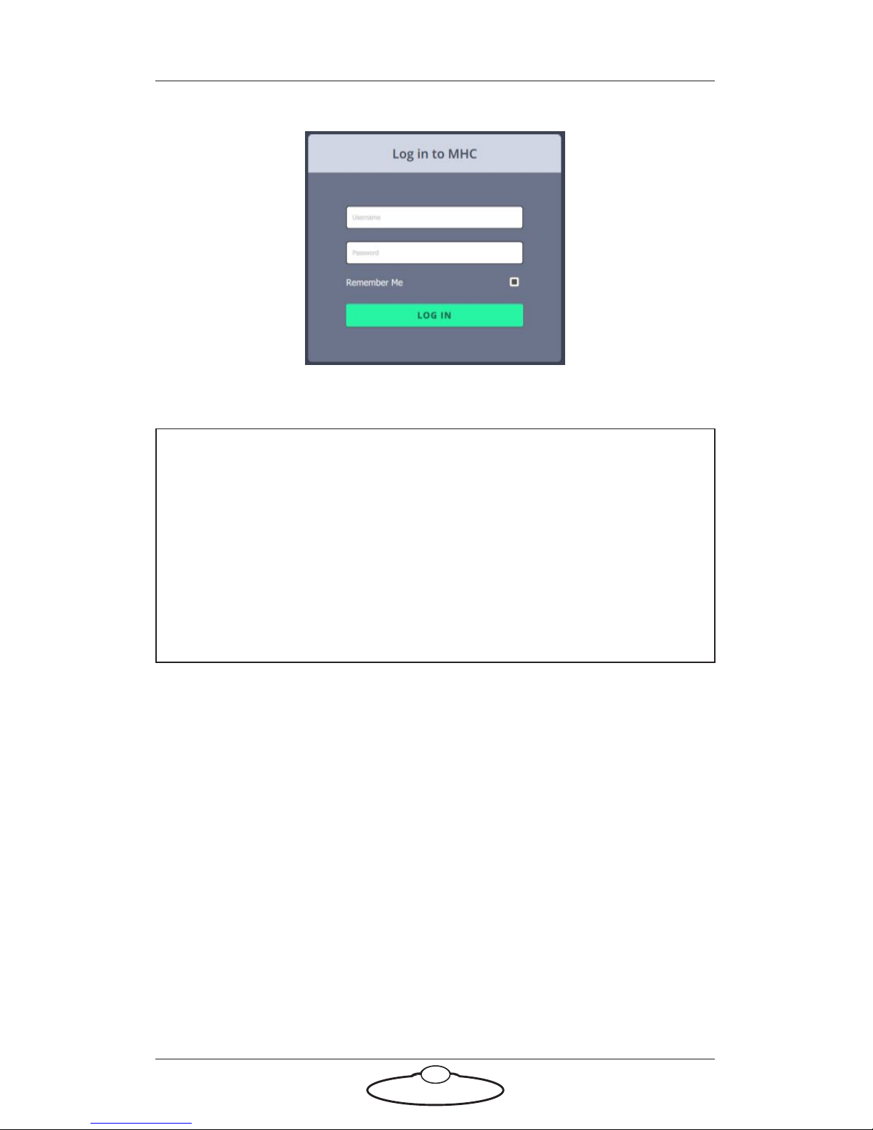
2. Log in to the MHC client as Administrator using the following
credentials:
Username: Admin
Password: Admin1234
Page 18
Note
At any time, if you need to restart MHC, perform the following steps:
1. Close the MHC Client and the MHC Server windows.
2. Double-click or tap the MHC Server desktop icon to launch it.
3. Double-click or tap the MHC Client icon to launch it. The
MHC Client can be launched on the same or a different
computer present on the same network.
Robotic Pod (Stadium) Quick Start Guide
14
Page 19
Robotic Pod (Stadium) Quick Start Guide
15
Network setup
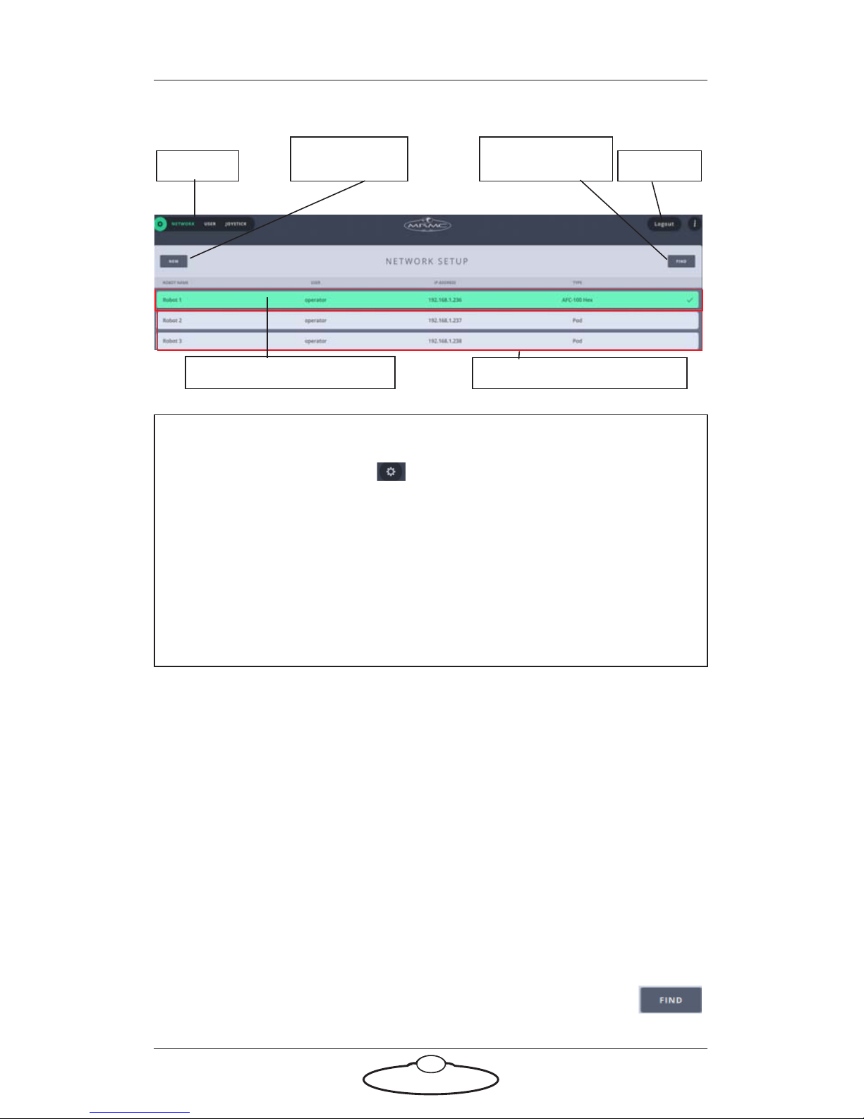
Heads on the network
Heads not on the network
Manual Pod
addition
Automatic Pod
addition
Settings Log out
Note
You can click the Settings ( ) button to display the Settings menu.
The tabs in the menu are:
Network – Settings regarding connected/connecting Pods
User – Add/change user accounts
The Settings menu is different for Administrator and User login. For
more information on Settings menu for the User login, go to Settings
menu on page 12.
When you log in as the Administrator, the NETWORK SETUP page
launches and provides a general overview of all the Pods linked to the
system’s network. The two row colours represent the status of the Pods:
Green: The Pod is connected and ready to operate.
Grey: The Pod with the IP address is not connected with the
system’s network or is not powered up.
Adding Pods
MHC allows you to add Pods in two ways:
Adding Pods by using FIND
You can click the FIND button to automatically find the
connected Pod(s). This will appear in a new row. Select the
Page 20
Robotic Pod (Stadium) Quick Start Guide
16
Pod’s row that you want to connect to and click the appearing ADD
button. This will connect the Pod to the system, and move it to the group
of the connected Pods (the green section).
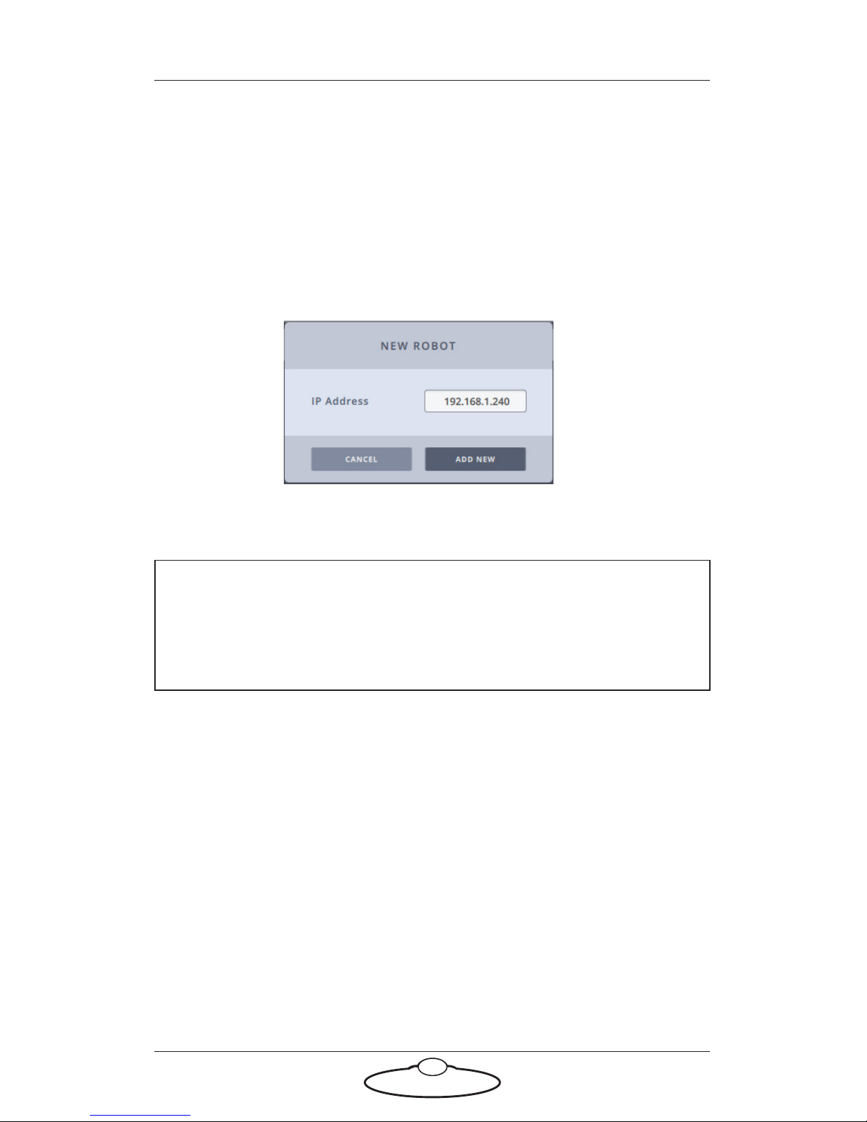
Adding Pods manually
Alternatively, if your Pod is not present at the time and will be connected
later, you can add the Pod by manually typing its IP address. If you know
the IP address of the Pod you want to add, you can use the NEW button,
then enter the IP address, and click ADD NEW.
Then, enter the TYPE of head and a NAME for it.The row for the Pod
stays grey until the Pod is actually present on the network.
Caution
Do not connect a Pod with the same IP address as another Pod on
the network. This would cause an IP address conflict and both Pods
will not function.
Changing a Pod’s name
You can change the name of a connected or disconnected Pod. The name
appears in the ROBOT NAME column. To change the Pod’s name:
1. Select the row for the Pod.
2. Click or tap in the box representing the name of the Pod.
3. Enter the name for the Pod.
Assigning Pods to user(s)
A Pod can only be used by a user, if it is assigned to the user. Assign a Pod
to the user by selecting the user from the drop-down list.
Page 21
Robotic Pod (Stadium) Quick Start Guide
17
Removing a Pod
To remove a Pod, click the appearing remove ( ) button on the Pod’s
row.
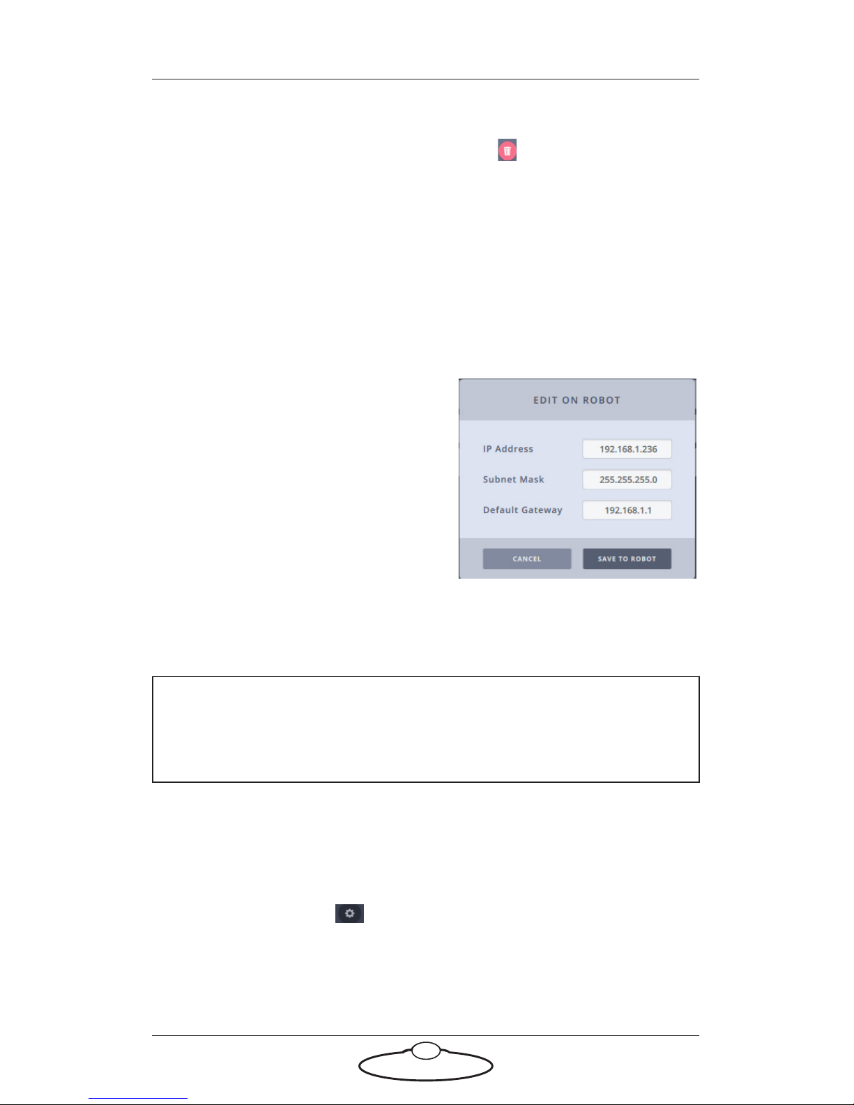
Editing network settings on the Pod
On the NETWORK SETUP page, only the disconnected (grey) Pod’s IP
address is editable. Only when the Pod is connected, can the network
settings be changed on it.
Select a robot that is connected (green) and click in the IP ADDRESS
box.
Use the appearing dialog box to change
the IP settings of the robot. Your
system will also automatically update
its local reference address, so you won’t
lose the connection to the edited robot.
Enter the IP Address, Subnet Mask,
and Default Gateway. These are
settings of the robot, not just the
references in MHC Client. By changing
these, you will override the settings on
the robot.
Note
You must be logged in as Administrator to change network settings
on the Pod.
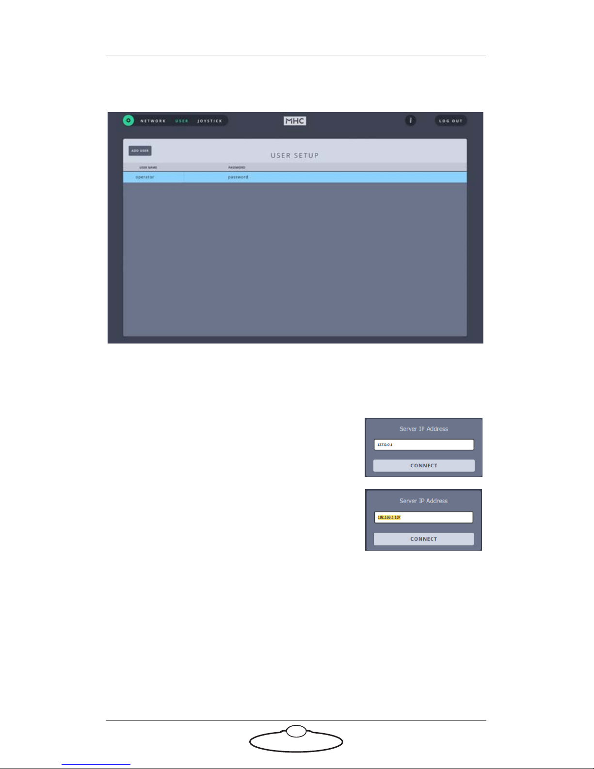
Adding users
By default, there is one User account added to the system. However, if you
require you can add more Users. To do this:
1. Click/tap Settings ( ) > User.
2. Click/tap ADD USER.
3. Enter the username and password that you want to assign to the
user.
Page 22
Robotic Pod (Stadium) Quick Start Guide
18
4. Click/tap Save.
Once user(s) are added, the Pods each of them can see can be assigned.
Changing the Server IP address
By default, if the MHC Server and Client are
running on the same PC, the Server IP
address is set to 127.0.0.1. However, if the
MHC Server is running on a PC other than
that of the MHC Client, specify the server IP
address when you start the MHC Client.
Logging in as a User
Once robots are added, accounts are created and robots are assigned to
users, log out of the Administrator login and log in as a User.
The default user credentials are:
username: operator
password: password
Page 23
Robotic Pod (Stadium) Quick Start Guide
19
TDCGraphics software
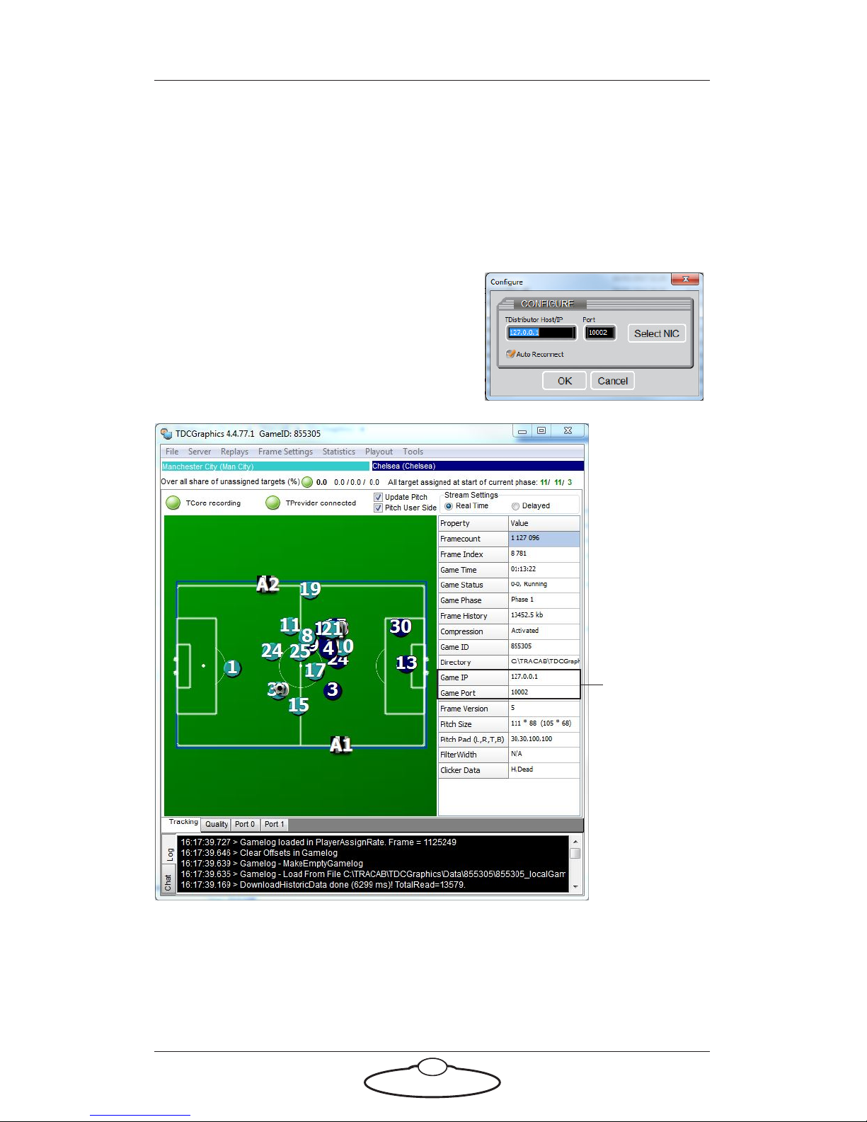
In the stadia environment, the Tracab server sends data to TDCGraphics
software which in turn assembles it in a format that can be read by MHC
in order to track the targets on the field. TDCGraphics is a tool that
allows you to specify additional clustering and zonal data and then send it
to MHC in the suitable format.
When you launch TDCGraphics, a dialog
box is displayed where you need to
specify the IP address of the Tracab
server.
IP address
and port
number of
the Tracab
server
Port tabs
Each port tab provides a port number for MHC Server to connect to, to
receive data and a configuration for defining the position of the pod
relative to the centre spot of the pitch and configuration of the zonal data
Page 24
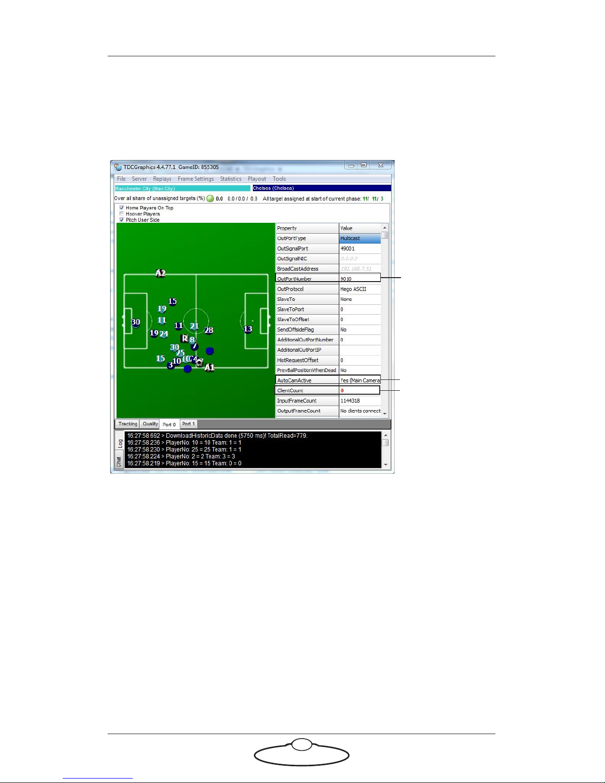
Robotic Pod (Stadium) Quick Start Guide
20
that will be sent. The zonal data can be either a position of general play
with field of vision (FOV), or a position of a cluster of players with FOV.
If the stadium setup requires more than one Pod to track zonal data, then
additional port tabs will be required for each Pod.
Port used as
source by
MHC
Used to
enable player
clustering
Changes to 1
if MHC
server is
connected
To specify zonal data:
1. Select the port tab on which you want to set player clustering.
2. Double-click AutoCamActive to display the Set Offset for Slave
Type window.
3. Check AutoCam active to turn zonal data on.
4. From the Camera Type field, select Player Cluster to set player
clustering as the FOV or select Master Game to set entire play as the
FOV.
5. Specify the X, Y, and Z coordinates of the head’s location with
respect to the centre of the football pitch. (This has to be measured
manually.)
Page 25
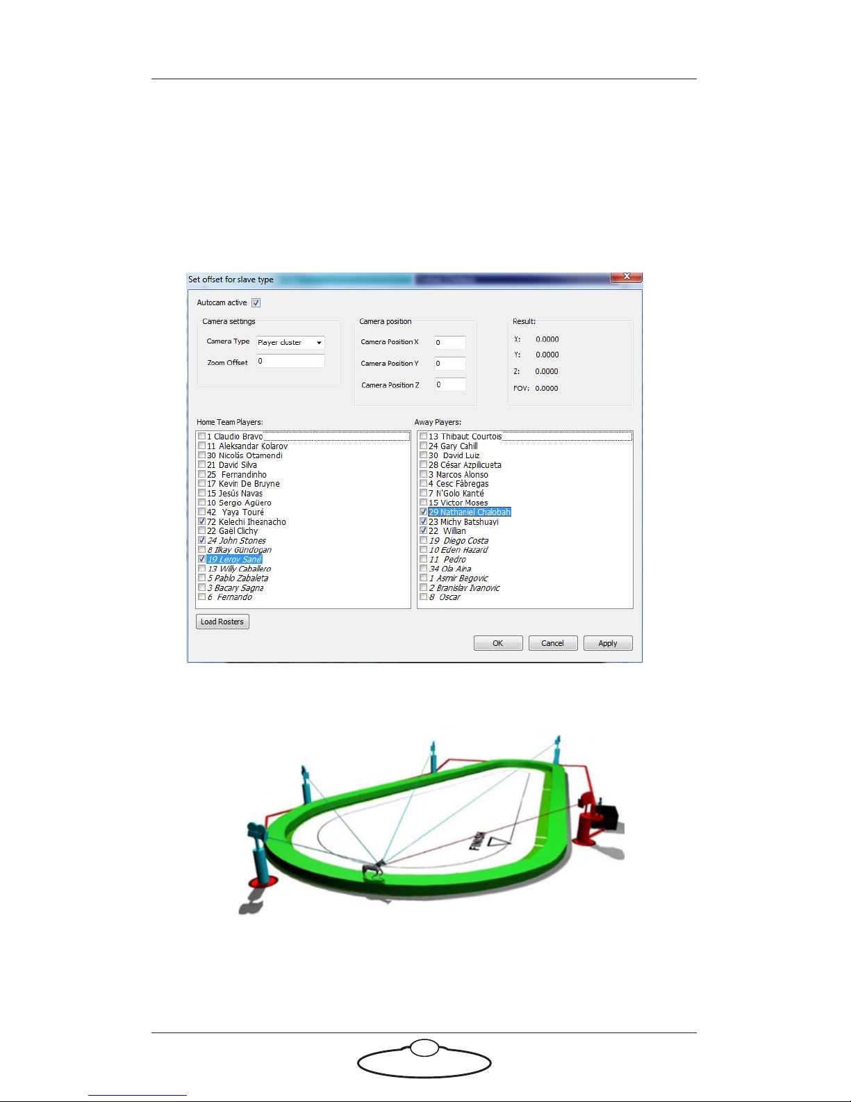
Robotic Pod (Stadium) Quick Start Guide
21
6. If you are setting player clustering, select the players that you want
to cluster.
In the Result area, the X, Y, Z, and FOV positions show the data of
the target that would be output to the MHC Server.
7. Click Apply and then click OK.
Polycam system
Polycam is a system containing multiple heads configured for fully
automated subject tracking for broadcast or monitoring. A Polycam
Page 26
Robotic Pod (Stadium) Quick Start Guide
22
system uses external data feed from a source (for example, ChyronHego)
and the cameras on the Pods are set to trigger or record the target.
Polycam settings
After starting TDCGraphics, you need to specify how the Polycam system
tracks moving subject, such as the players on the football field, and
configure the MHC server to communicate with the Tracab system.
To do this:
1. Log in to the MHC client as a user.
Page 27
Robotic Pod (Stadium) Quick Start Guide
23
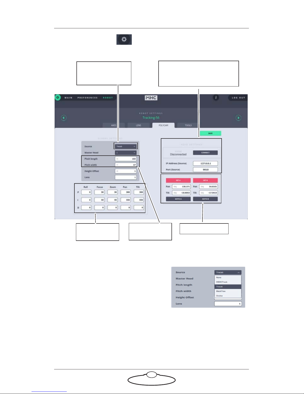
2. Click the Settings button, and select ROBOT. This opens the
Robot Settings page. Select POLYCAM to specify the polycam
settings.
IP address and port number
of the system that the head is
communicating with
System with which
the network link is
established
Dimensions of
the field
A and B points PID controller
settings
3. Under GLOBAL SETTINGS, specify:
The name of the system that
the camera needs to
communicate with. In this
case, select Tr ac ab .
Select the head that you want
to set as the master head. This
is useful, when you are
player-tracking and have the
Autozoom on, the framing on
the master head will be
automatically used by all the
other heads.
Page 28
Robotic Pod (Stadium) Quick Start Guide
24
Specify the Pitch length and Pitch width. Specify the Height
Offset which is how far off the ground the Pods should target.
If height offset is set to zero, the tracking system will target
ground level. A value of 1m is usually used, as this is about
waist height of a football player.
Specify the PID controller settings. A PID controller is a
control loop feedback mechanism. This is used to fine tune the
robot’s response to the incoming tracking data. Each axis of the
head has a value for:
– P (Proportional) accounts for present values
– I (Integral) accounts for past values
– D (Derivative) accounts for possible future values
The values entered are used by the PID controller to
continuously calculate the required velocity of the axes to keep
the target in frame. Changing these values will affect the
smoothness and accuracy of tracking.
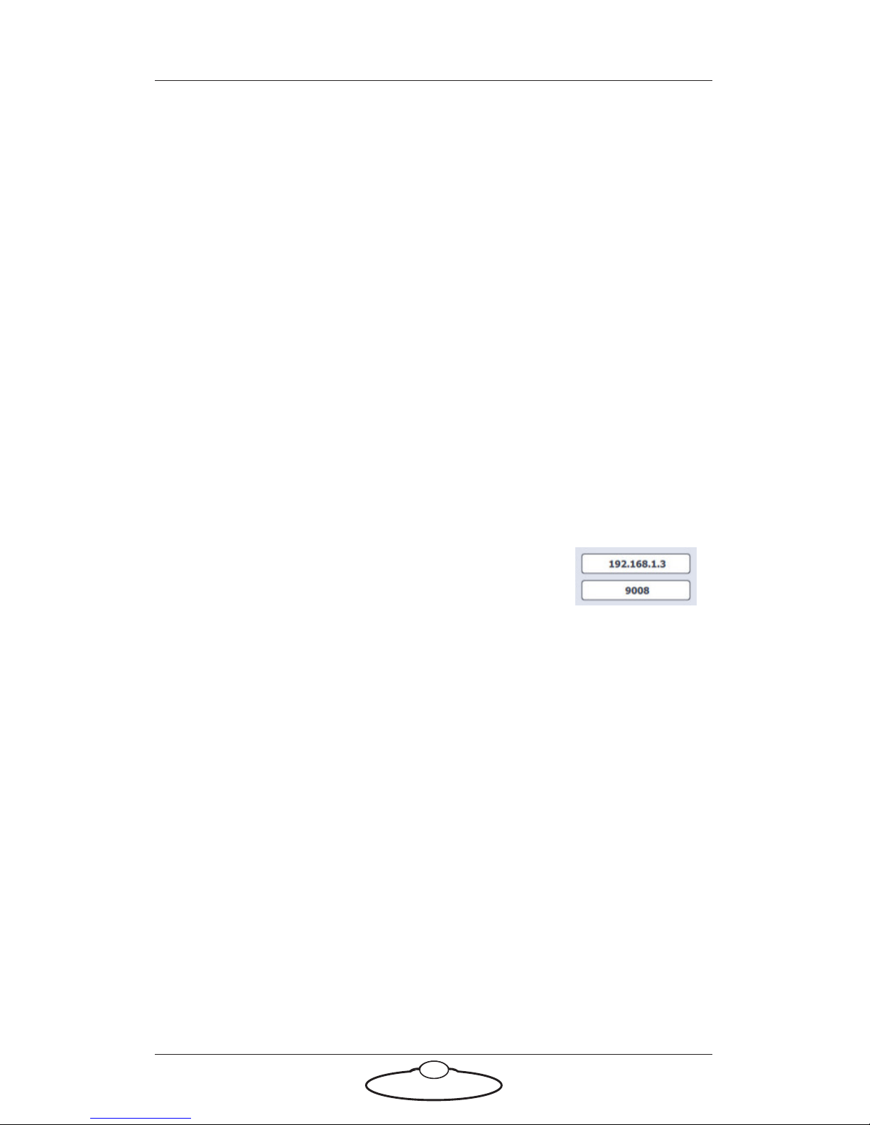
4. Under HEAD SETTINGS, specify the IP
address and port number of the incoming
connection of the data from Tracab. Note that
the port number is the same as that in the
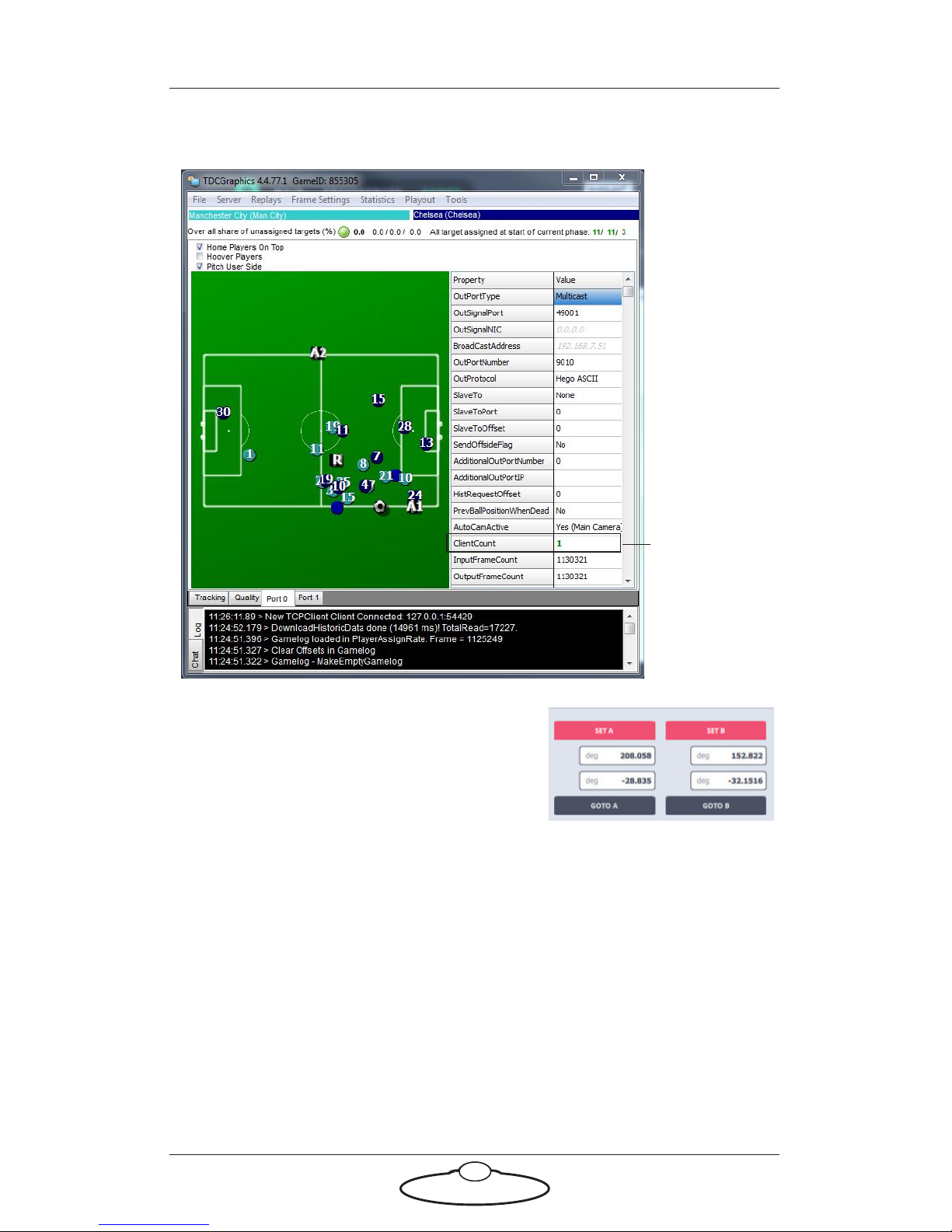
TDCGraphics software in the OutPortNumber field. Click
CONNECT.
Page 29
Robotic Pod (Stadium) Quick Start Guide
25
Note that the value in ClientCount field in TDCGraphics changes
to 1.
Changes to 1
when MHC is
connected to
TDCGraphics
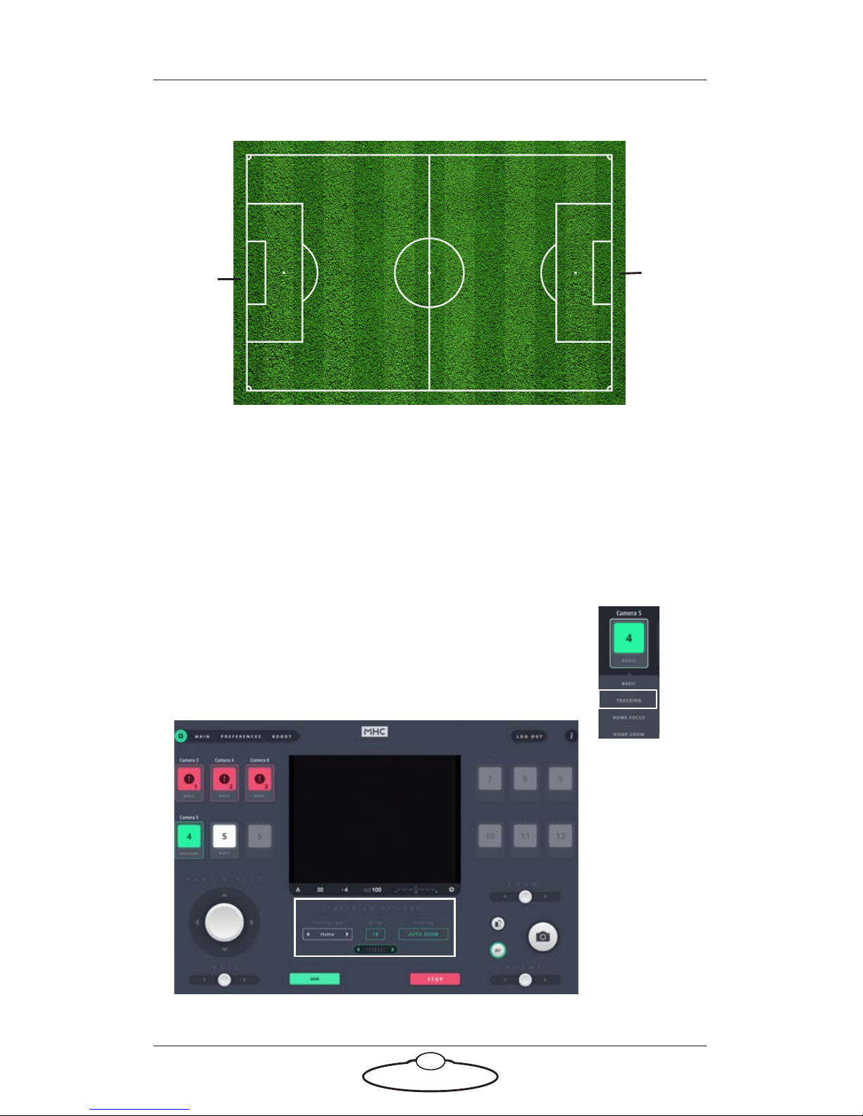
5. Use the SET A and SET B buttons to
specify the range of physical travel of
the head movement. For example,
Point A is the angular position in the
middle of the goal post of Team A and
Point B is the angular position in the
middle of the goal post of Team B. These positions along with the
dimensions of the football pitch will enable the camera to calculate
the relative position of the subject on the field.
Page 30
Robotic Pod (Stadium) Quick Start Guide
26
.
+
Point A
Point B
+
6. Click SAVE.
7. Use the GOTO A and GOTO B buttons to test the settings specified.
Tracking data
Tracking does not automatically begin after specifying the polycam
settings. You will need to enable tracking for each Pod. To do this:
1. Click/tap and hold the head you want to enable
tracking on.
2. Select Tracking.
Page 31
Robotic Pod (Stadium) Quick Start Guide
27
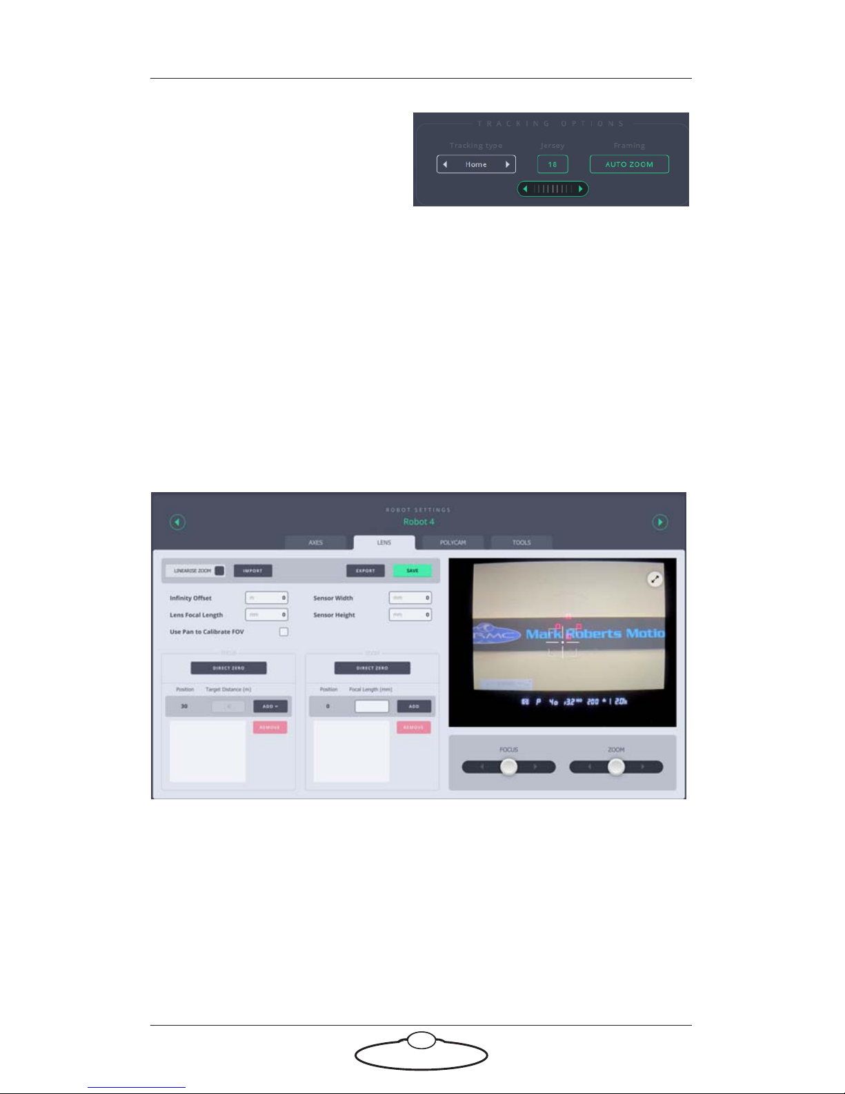
3. On the MAIN screen, use
the TRACKING OPTIONS
section to specify the
options for tracking. For
example, you can select the
Tracking type as Home,
Away, Ball, Referee, or Zone. Use the dial to select the Jersey
number of the player you want to track. You can also specify
whether you want to AutoZoom. You can select the Tracking type as
Zone if tracking a player cluster. and click SAVE to begin tracking.
Once you set player clustering on, the player cluster data received
from the Tracab system would be in accordance with the player
clustering settings specified in TDCGraphics.
Lens tab
Settings in the Lens tab stores information relating to the individual
lenses characteristics, such as its focal length and throw of the manual
Focus ring so that the system knows which lens is attached. These settings
are used when you are using an external tracking system or when you
need to control the camera lens in the robot in a more advanced way. A
tracking system requires Focus and Zoom axes to keep the moving target
in focus and in frame without apparent change in target size. However,
the relationship between Focus motor position and target distance, and
Page 32
Robotic Pod (Stadium) Quick Start Guide
28
Zoom motor position and focal length is not linear. Therefore, the Zoom
and Focus axes need to be linearised or calibrated allowing the head to
control the Focus axis in terms of target distance and the Zoom axis in
terms of focal length.
For details on setting up a tracking system using MHC, refer to Polycam®
tab.
Linearise Zoom button
Linearise Zoom is a toggle button that allows you to enable Zoom
linearisation during Goto moves, using the parameters shown in the
table.
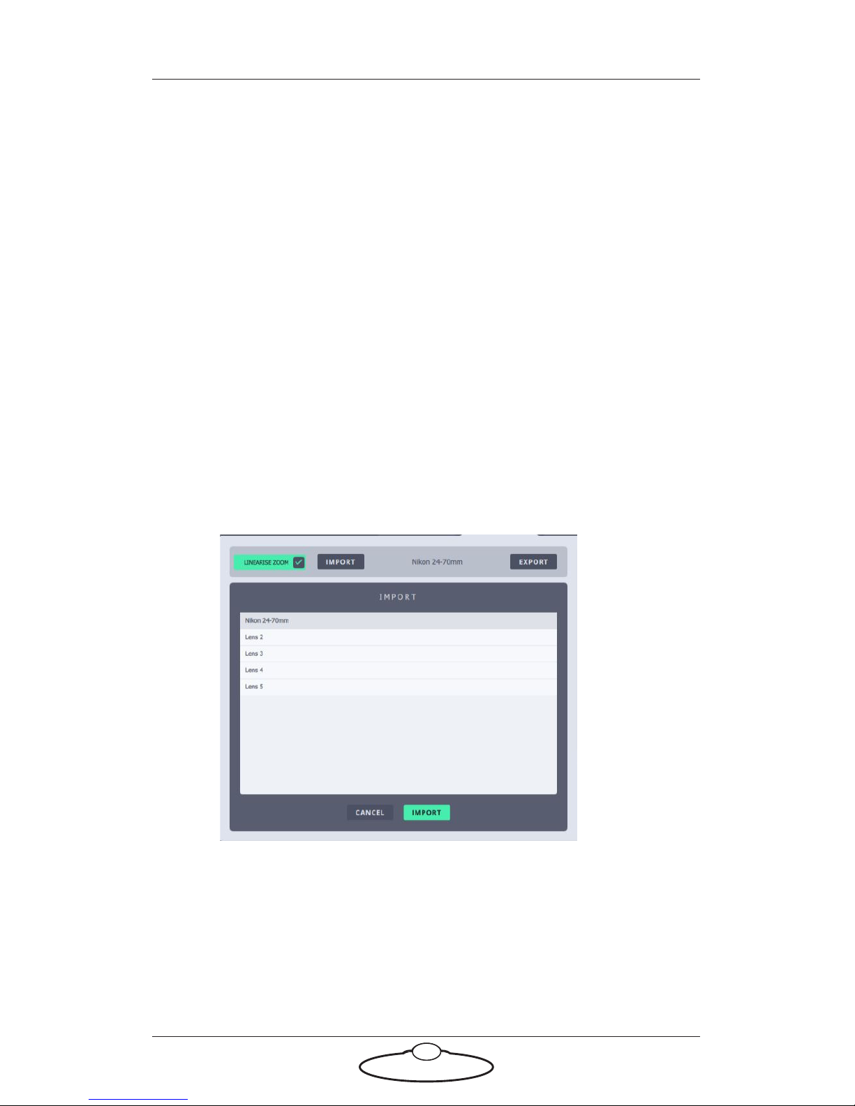
Importing lens settings
Use the IMPORT button to populate a previously saved lens profile on
the Lens tab. Note that any value changed will be stored on the head
immediately. Normally, as long as you are using the same lens on the
head, you will not need to change this.
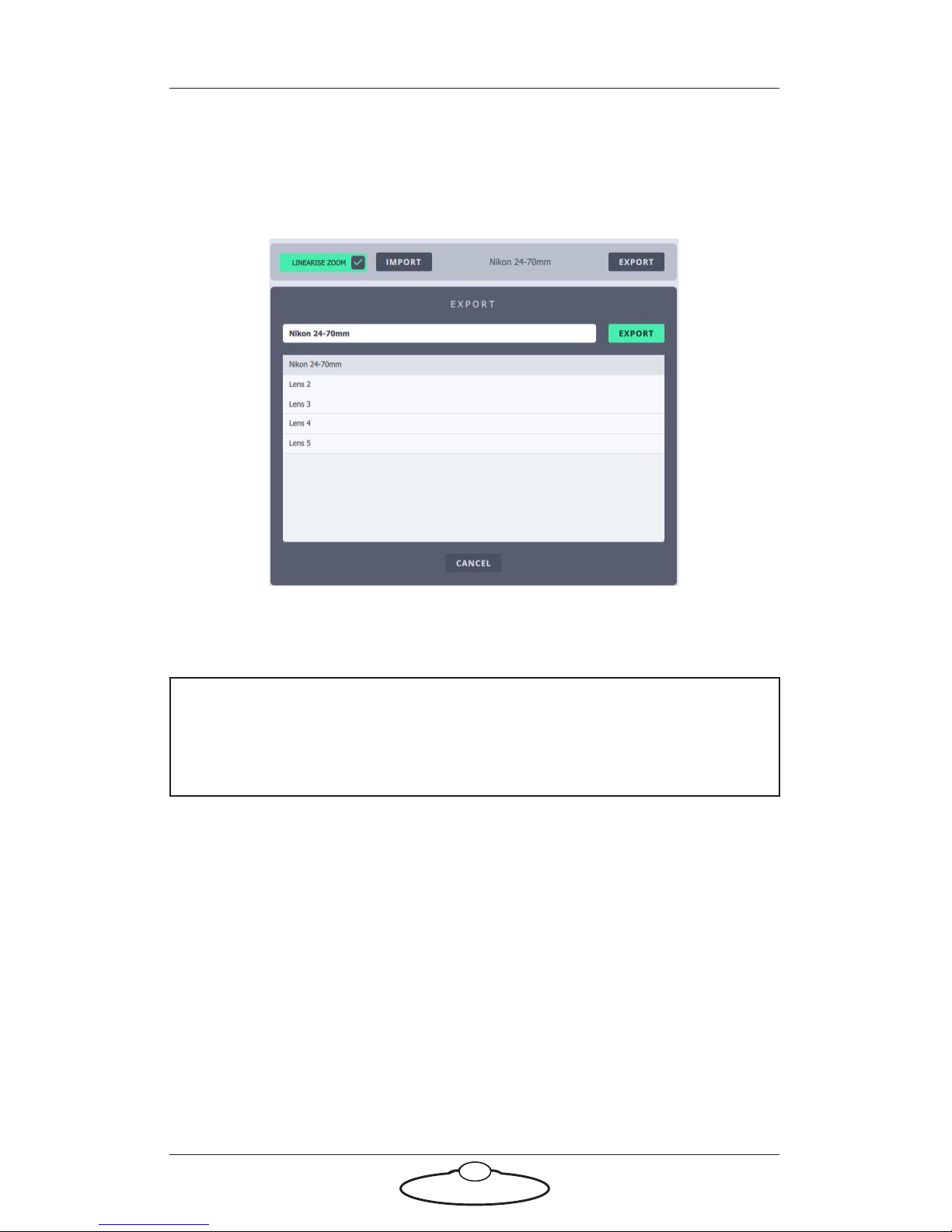
Exporting lens settings
You can save the current populated field characteristics in a lens
configuration file on the local disk. In other words, clicking the EXPORT
button will save the current values to the local disk.
To export a lens configuration file:
Page 33
Robotic Pod (Stadium) Quick Start Guide
29
1. Change the required settings on the Lens tab.
2. Click EXPORT.
3. Select one of the existing lens configurations. Rename the
configuration.
4. Click EXPORT.
Note
For the Lens calibration settings to work, you should have already set
the soft limits in the AXES tab.
Infinity offset
Before calibrating the Focus axis, it is important that the axis is correctly
zeroed. Sometimes, the Focus axis might not zero at infinity. In this case,
set up the zeroing to where you want it to go and zero the lens, then move
it to Infinity, and use the reading over the Focus axis control on the Main
page to store this distance as the Infinity Offset.
Lens Focal Length
Specify the focal length of the lens. If the focal length of the lens is not
fixed, then use a number in the middle of the focal length range of the
camera.
Page 34

Robotic Pod (Stadium) Quick Start Guide
30
Sensor Width and Height
Specify the Sensor Width and Sensor Height for the sensor of the lens.
Use Pan to Calibrate FOV
When using pan and tilt along with Zoom, a small movement in the pan
axis on narrow zoom can result in greater shift in FOV than the same
movement in pan axis on wide zoom. Therefore, the Zoom axis might
need to be scaled to avoid such shifts. Specify whether you want to use
Pan to calibrate FOV.
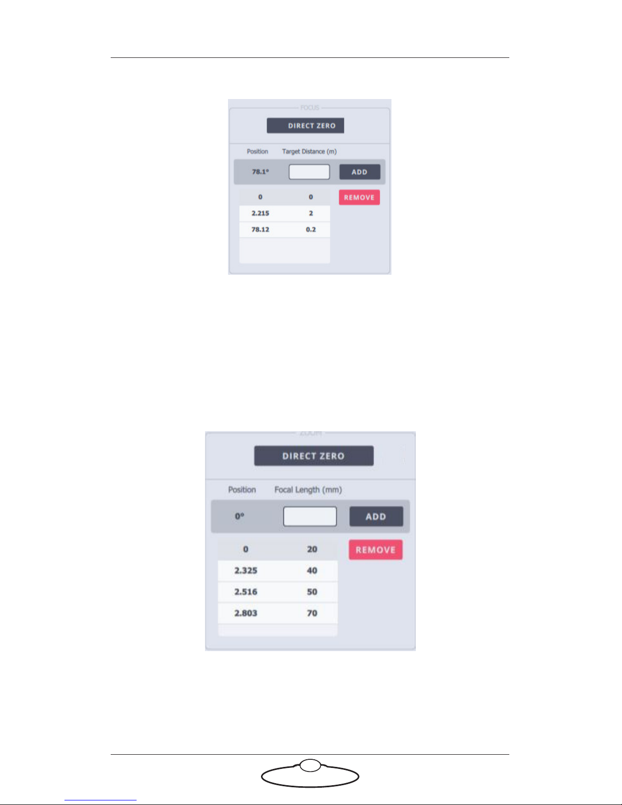
Focus calibration
To calibrate the Focus axis, you need to specify a linearisation table in
which each line contains a Target Distance and a matching Focus
Position. The Target Distance is measured in metres, and the Focus
Position is specified by using the Focus control. To create the linearisation
table:
1. Ensure that the soft limits are set correctly on the AXES tab.
2. Ensure that the Focus ring on the camera is at the minimum
position.
3. Click the ADD button to add the first line as the Target Distance
of infinity and Focus Position of 0.0.
4. The next value must be in increasing Focus position and decreasing
target distance:
4.1 Use the Focus control to drive the Focus Position and type the
Target Distance in the box.
4.2 Click the ADD button.
5. The third or final position must be the maximum position that you
set as the soft limit in the Axis tab. Use the marking of the lens to
decide how many entries you add in the translation table. Normally,
you would add about three entries for Focus linearisation.
Page 35
Robotic Pod (Stadium) Quick Start Guide
31
Zoom linearisation
By entering in the MHC a few Zoom motor positions and the their
respective focal lengths, the software can work out for any desired focal
length what the Zoom motor position should be. This means that you can
plot a move on the Zoom axis in terms of focal length, and the zoom will
be driven to change the focal length in a smooth manner. Normally the
focal length (or field of view) change does not move steadily with a
constant movement on the Zoom lens.
To linearise the Zoom axis, you need to specify a linearisation table in
which each line contains a Focal Length and a matching Zoom Position.
The Focal Length is measured in millimetres, and the Zoom Position is
specified by using the Focus control. To create the linearisation table:
Page 36
Robotic Pod (Stadium) Quick Start Guide
32
1. Ensure that the soft limits are set correctly for the Zoom axis on the
AXES tab.
2. Ensure that the Zoom ring on the camera is at the minimum
position (at widest zoom).
3. Specify the focal length for the widest zoom.
4. The next value must be in increasing Zoom position and respective
focal length:
4.1 Use the Zoom control to specify the Zoom Position and type
the Focal Length in the box.
4.2 Click the ADD button.
5. Use the marking of the lens to decide how many entries you add in
the linearisation table. Normally, you would add about 3 to 7 entries
for Zoom linearisation.
6. The last entry must correspond to the upper travel limit of the
Zoom axis.
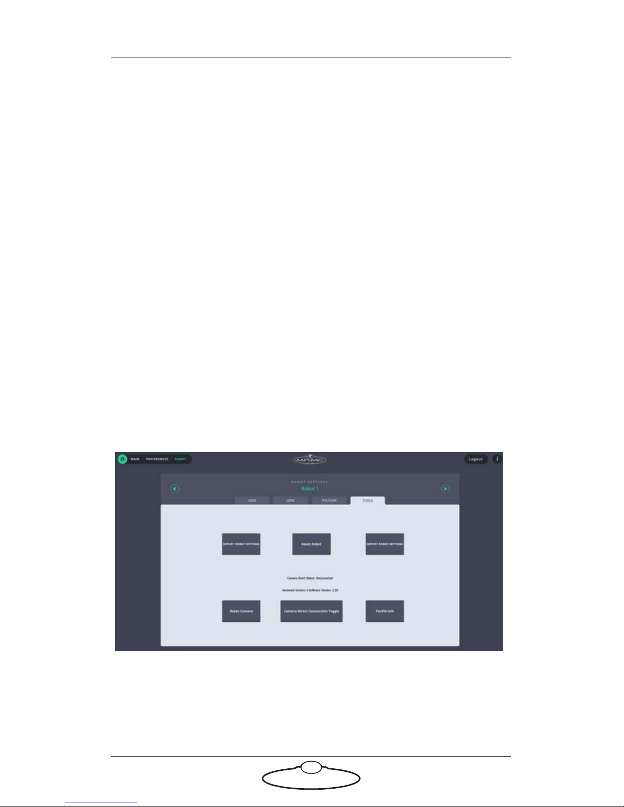
Tools tab
The TOOLS tab allows resetting of the head and exporting and importing
MHC settings:
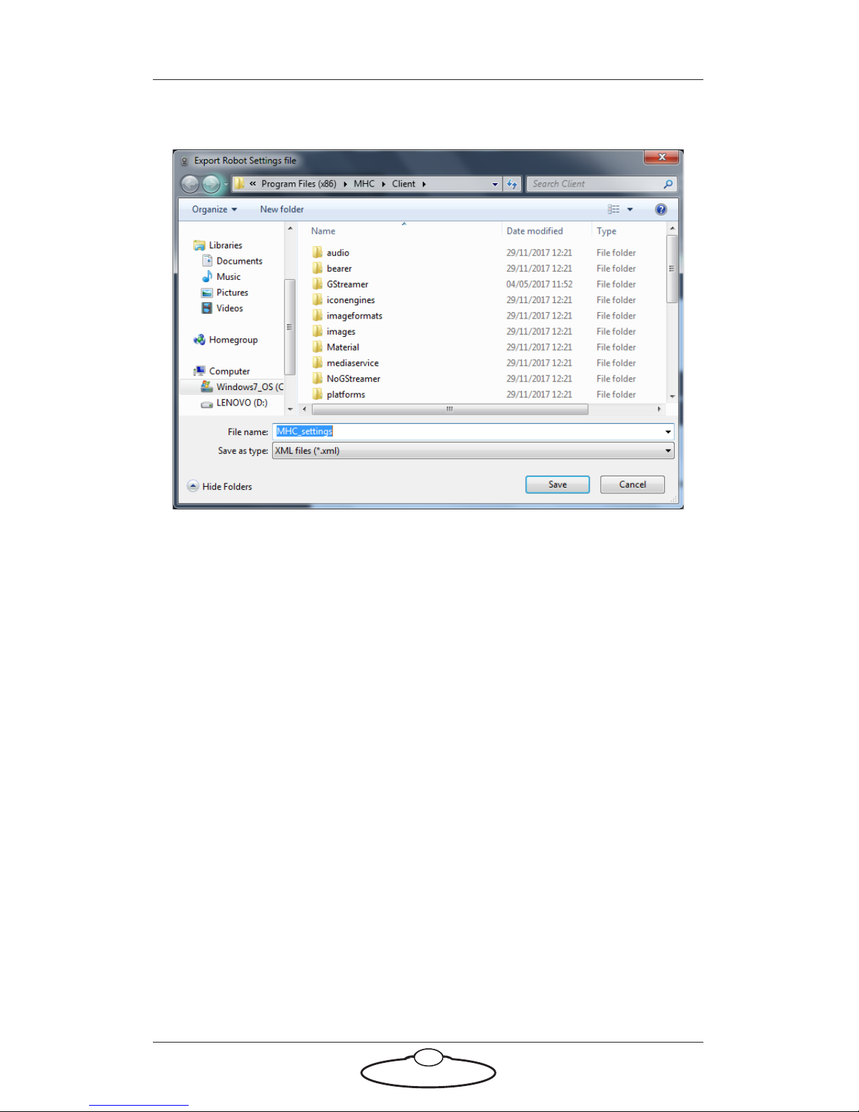
EXPORT ROBOT SETTINGS
Use this button to store all the settings in MHC to an XML file which you
can import later. This can be used to copy settings to another robot or
save the factory settings to be restored later.
Page 37
Robotic Pod (Stadium) Quick Start Guide
33
1. Clicking the button will open a dialog box, enter the name of the
XML file.
2. Click Save.
Reset Robot
Clicking Reset Robot resets the axes (Hex) board in the head. Use this
option when the camera has crashed/frozen or a power cycle is required.
Page 38
Robotic Pod (Stadium) Quick Start Guide
34
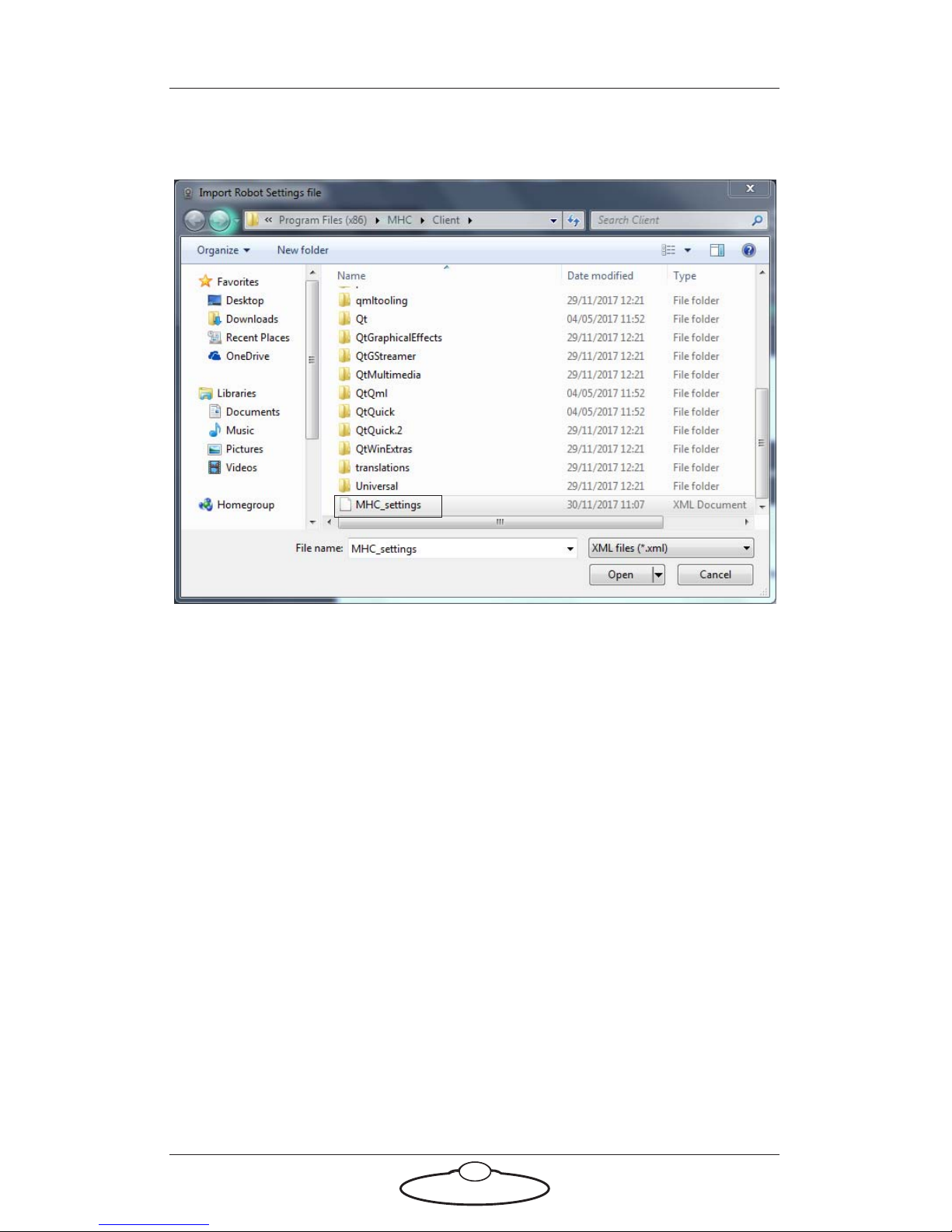
IMPORT ROBOT SETTINGS
Use this button to import MHC settings from an XML file.
Reset Camera
Clicking Reset Camera resets the Nikon camera as-though you
power-cycled it.
Camera Direct Connection Toggle
Resets the camera to be connected to the PC via USB.
TenPin Init
Clicking TenPin Init reinitialises the TenPin board.
Subsequent sessions
After you have initially set up the system for your pod head and
preferences, subsequent sessions take less time to set up, especially if you
have not disconnected control cables or moved sites. For subsequent
sessions at the same site you typically need to do the following at the start
of every session.
1. Attach the power cables to the head and PC.
2. Launch the MHC server.
Page 39

Robotic Pod (Stadium) Quick Start Guide
35
3. Launch the MHC client on each user PC.
4. Home the zoom and focus axes.
5. Define the polycam options for the match.
Page 40
36
Robotic Pod (Stadium) Quick Start GuideRobotic PodQuick Start Guide
Appendix 1 Troubleshooting
Typical symptoms, causes, and actions
Symptoms Cause and/or action
Pod head did not
appear connected in
MHC
Check that all cables are connected, and all
devices have power.
Check you have added the correct IP address of
the Pod head in MHC.
If you have connected more than one Pod
heads, connected the MRMC system to
another local network, or moved the Pod head
between networks, check that correct addresses
have been entered in MHC.
The LEDs on the Pod
head did not light up.
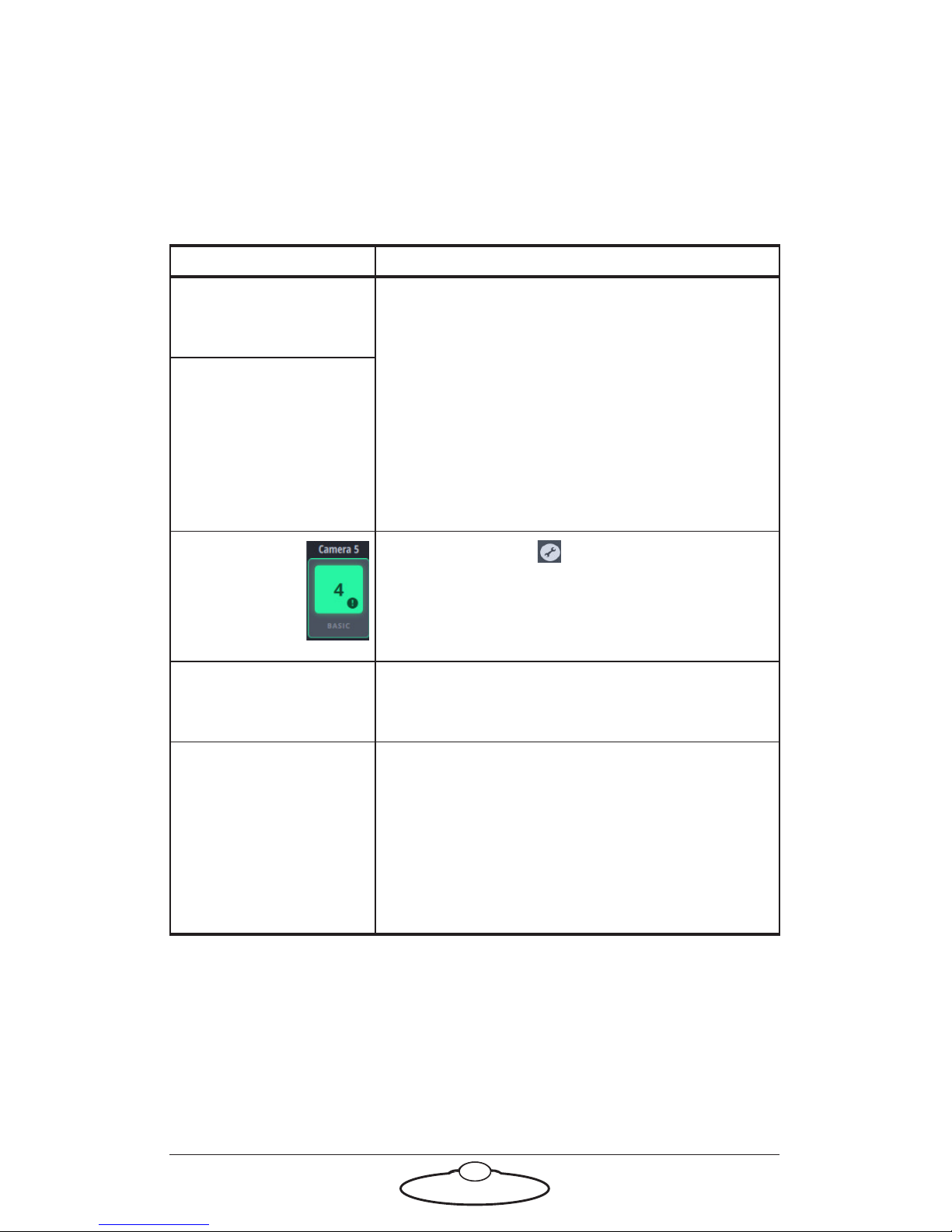
A ‘!’ appears
with the Pod
head icon in
the MHC
Main screen.
Click the spanner( ) icon appearing below
the Pod head icon to allow MHC to correct the
error.
Pod tracking is not
accurate
Ensure that the PTA is installed perfectly
levelled to the ground. Ensure that you have
checked this with spirit level.
While tracking the
camera is pointing in
the wrong direction.
The Pan axis must move to the left when
position is moved positively. If it is incorrect,
then scaling for the axis will need its sign
changing.
The Tilt axis must move up when position is
moved positively. If this is incorrect, then
scaling for the axis will need its sign changing.
Page 41

Robotic Pod Quick Start Guide
37
Notes
Page 42

Robotic Pod Quick Start Guide
38
Notes
Page 43
39
Robotic Pod (Stadium) Quick Start GuideRobotic PodQuick Start Guide
Appendix 2 Pod connectors
Connector pin-outs
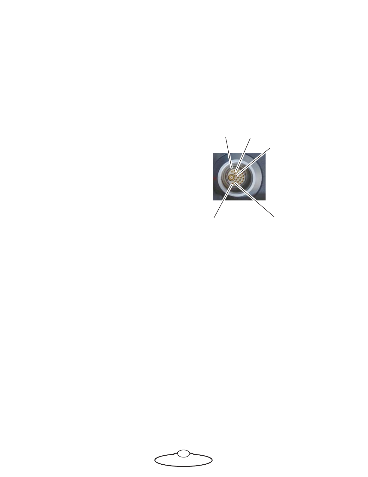
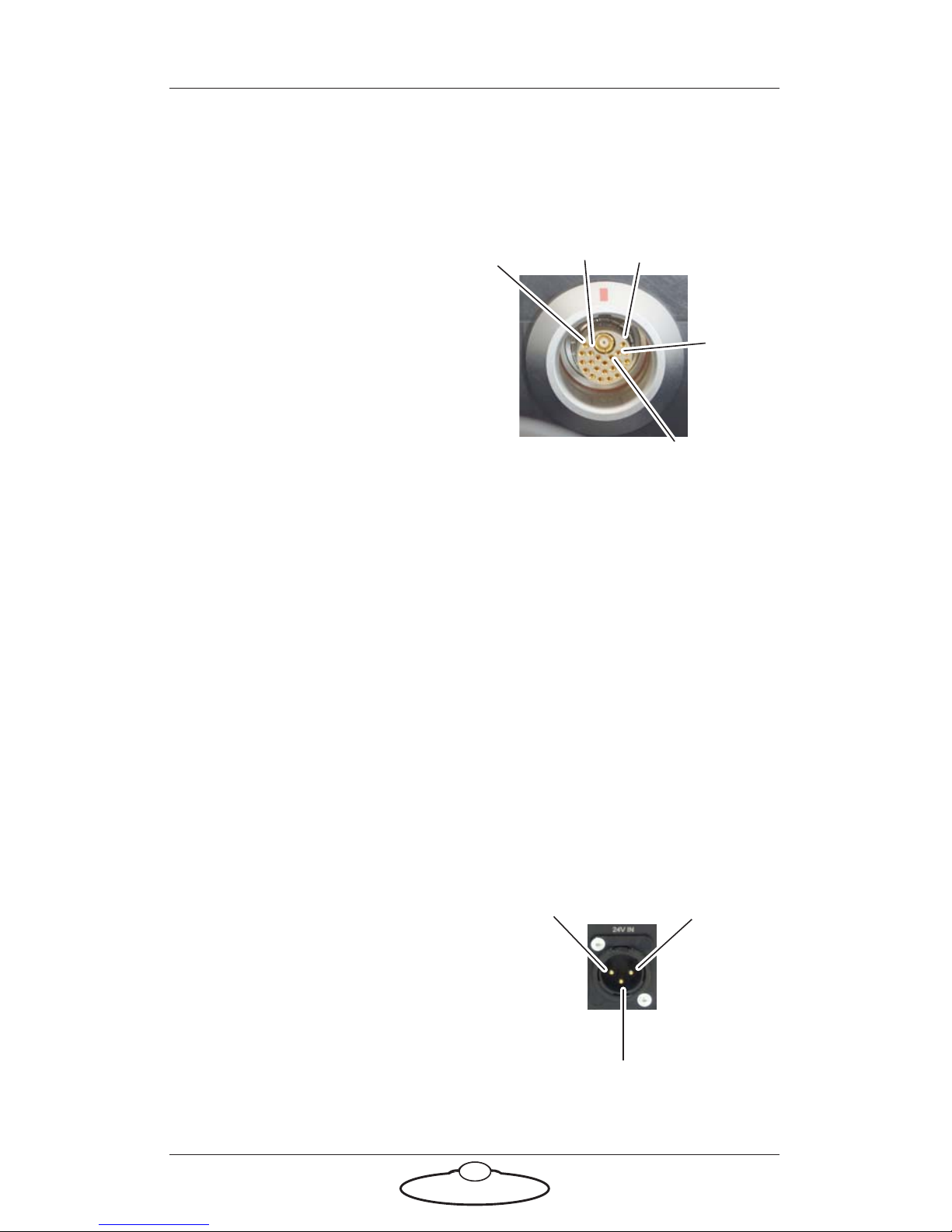
Panel mount connector
Panel mount connector is the 22-way (female) connector of type
EGG.3K.822.CLL1 on the POD and on the PTA.
1. 24V
13
12
19
22
1
2. GND
3. 24V
4. GND
5. 24V
6. GND
7. Ethernet 1
8. Ethernet 2
9. Ethernet 3
10. Ethernet 4
11. Ethernet 5
12. Ethernet 6
13. Ethernet 7
14. Ethernet 8
15. CANL
16. CANH
17. Motor+ (ROLL)
18. Motor-
19. Encoder A
20. Encoder +5V
21. Encoder B
22. Motor Limit (detect if motor is connected)
Page 44
Robotic Pod Quick Start Guide
40
Panel mount connector
Panel mount connector is the 22-way (female) connector of type
EGG.3K.822.CLL1 on the Pod base and in the power supply box.
1. 24V
13
19
22
112
2. GND
3. 24V
4. GND
5. 24V
6. GND
7. Ethernet 1
8. Ethernet 2
9. Ethernet 3
10. Ethernet 4
11. Ethernet 5
12. Ethernet 6
13. Ethernet 7
14. Ethernet 8
15. Not assigned
16. N/C
17. N/C
18. N/C
19. N/C
20. N/C
21. N/C
22. N/C
Power In connector
Power to supply the head and the power output connector. It is a XLR
3-Way (Male) connector. The Pod can run from 12-35 Volts DC.
1. GND
2
1
3
2. N/C
3. +24V
Page 45
Robotic Pod Quick Start Guide
41
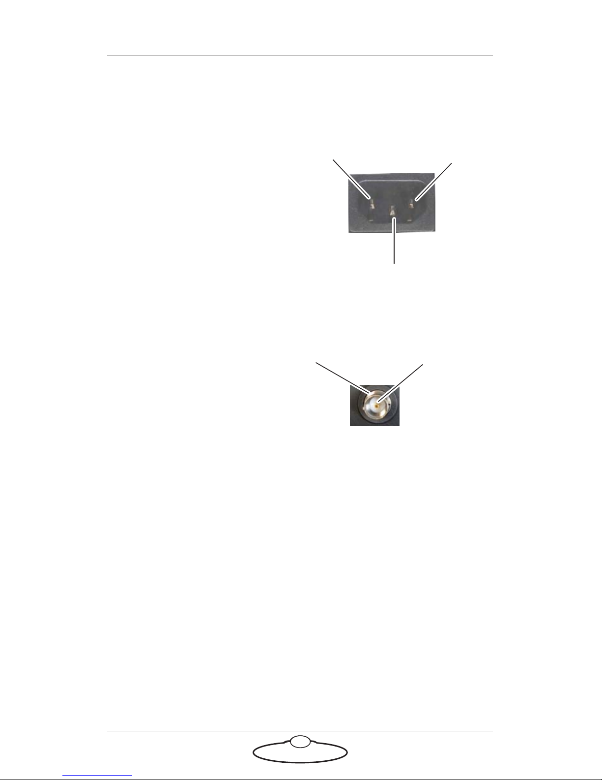
Mains In connector
Power input connector for the Pod head. It is a 3-Way (Male) C14 IEC
connector. 240 Volts AC.
1. Earth
2
3
1
2. Live
3. Neutral
SDI Out Connector
Connector for SDI Video signal from the camera.
1. Video Out (HD or SD)
(Centre
2
1
2. GND
Page 46

Robotic Pod Quick Start Guide
42
Notes
Page 47
43
Robotic Pod (Stadium) Quick Start GuideRobotic PodQuick Start Guide
Appendix 3 Specifications
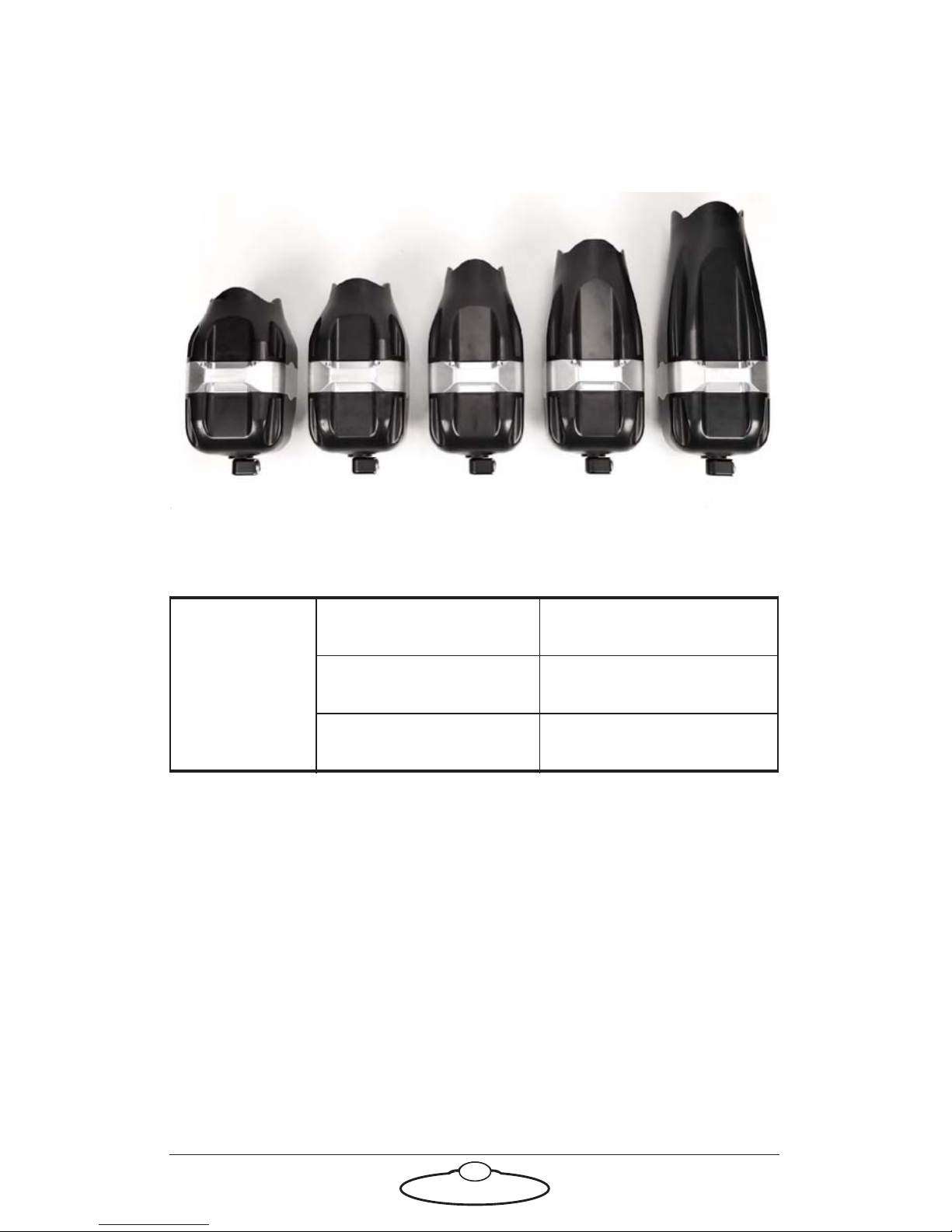
24-120mm 70-200mm 80-400mm 200-500mm24-70mm
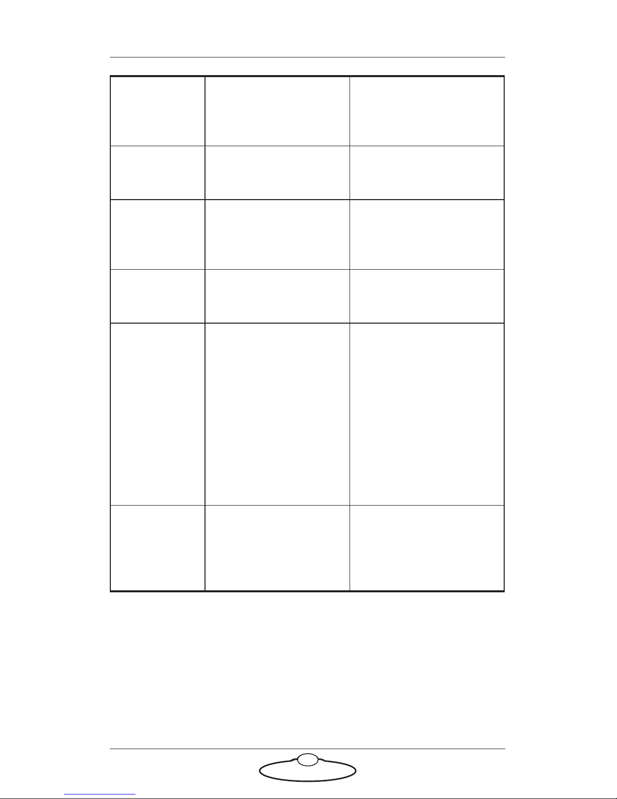
There are five types of robotic Pods based on the camera lens within.
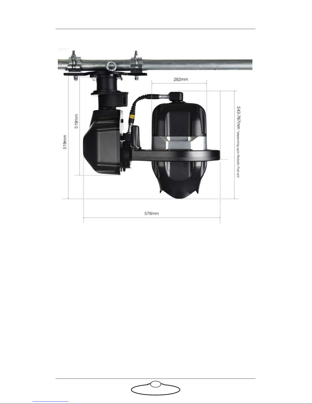
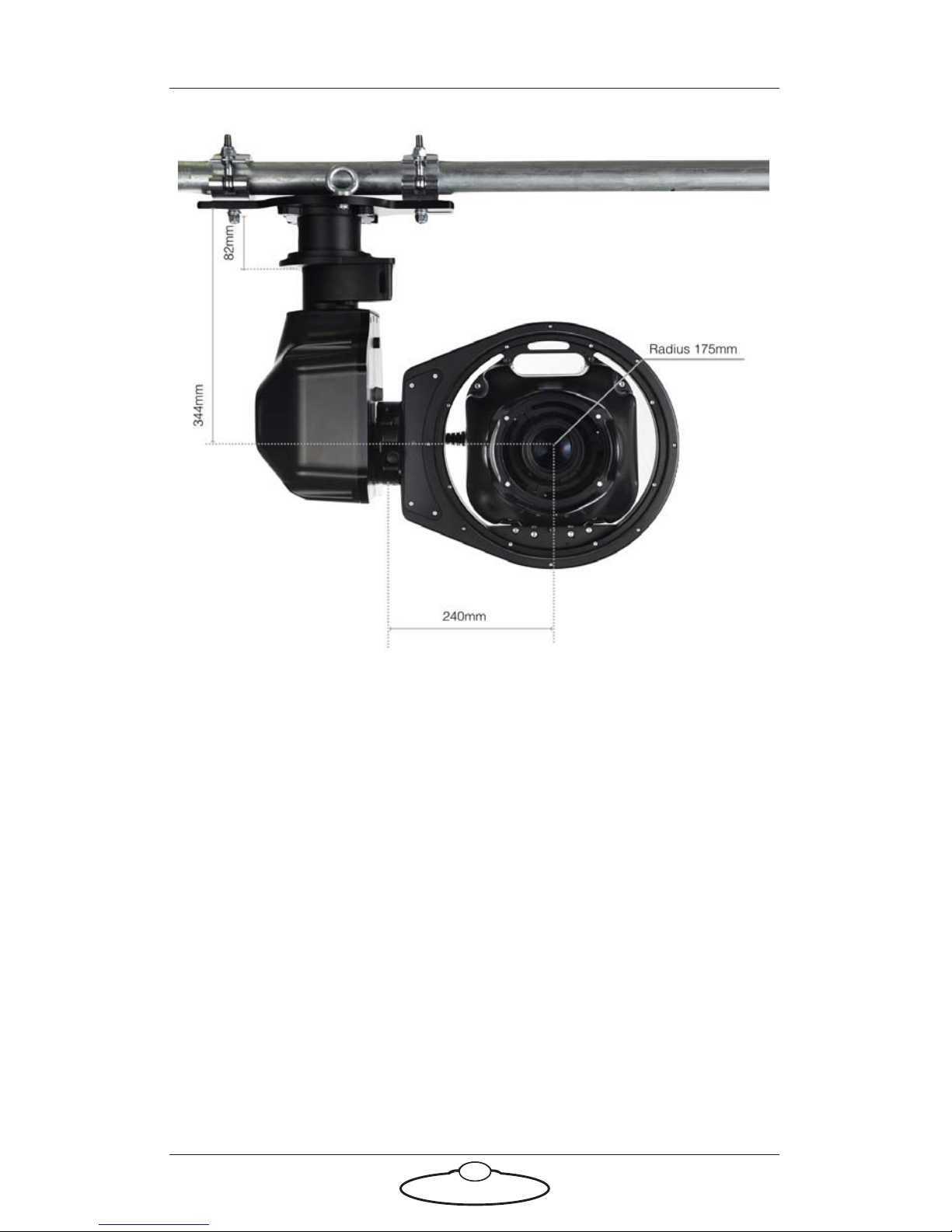
Size Total height 52cm-58cm
Total width 58cm
Operational space ~ 1.2m
3
Page 48
Robotic Pod Quick Start Guide
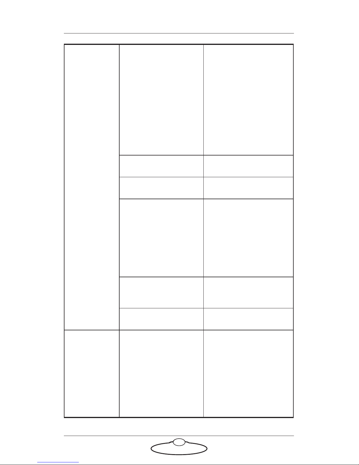
44
Weight Robotic Pod Between 7-10kg
depending upon the
unit
24-120mm RP: 8.4kg
24-70mm RP:
70-200mm RP:
80-400mm RP: 9.7kg
200-500mm RP: 10.5kg
Arm 11.8kg
Roll 4.71kg
Connection cable
(long)
5m: 1.10kg
10m: 2.10kg
15m: 3.10kg
20m: 4.10kg
30m: 6.10kg
Connection cable
(short)
0.30kg
Breakout Box 4.00kg
Connections RJ45 (1000base-t)
SDI (3G, Maximum
output 1080p 50/60
fps)
Fibre (Optional plug
in SFP for optical SDI
output)
Page 49
Robotic Pod Quick Start Guide
45
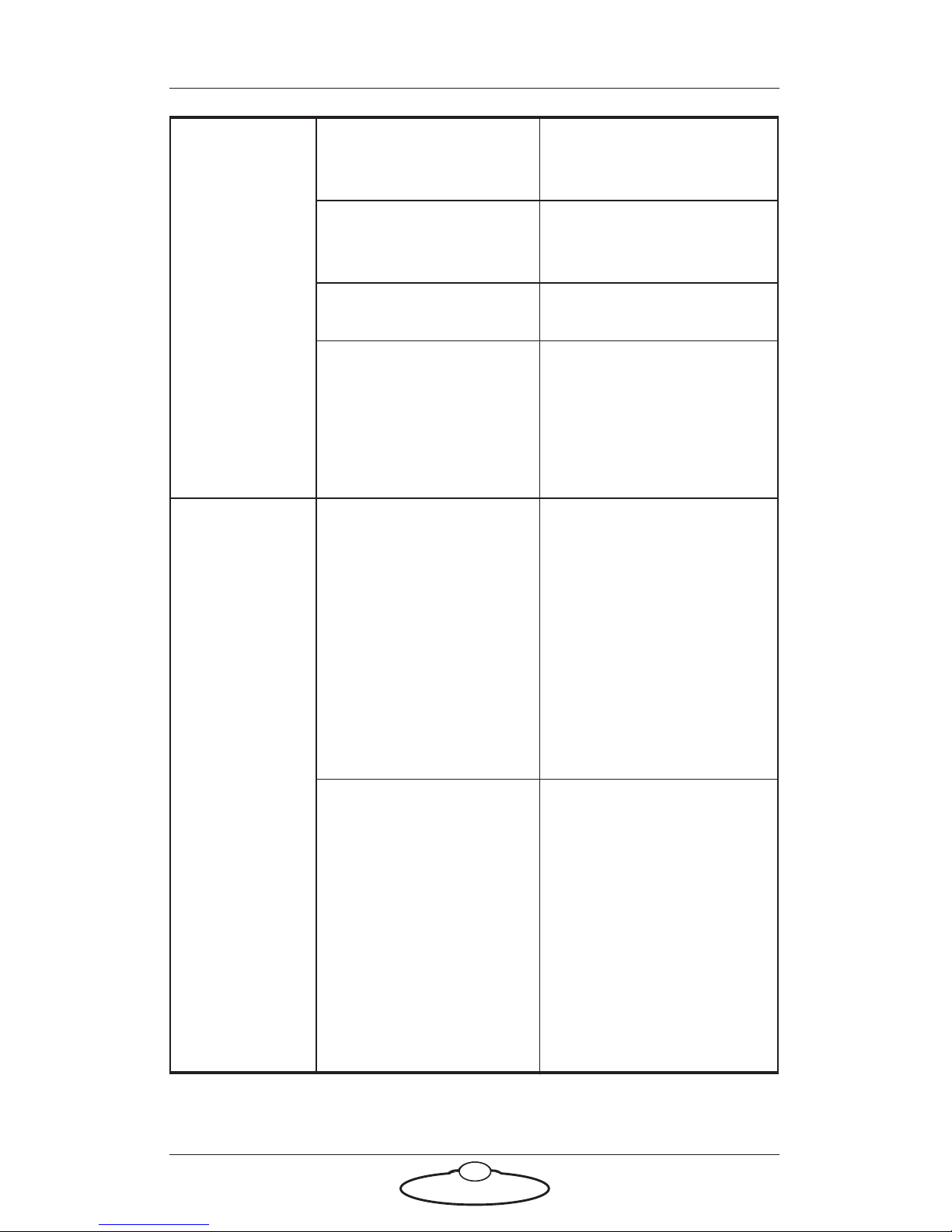
Power
requirement
s
24 Volts DC 16A
Temperature
range
0-45 °C (32-113 °F)
Humidity
tolerance
0% to 85% relative
humidity,
non-condensing
Maximum
speed
135 ° a second
Axes Pan (max 180° a
second, infinite
movement)
Tilt (max 180° a
second/340°
movement)
Roll (max 90° a
second, infinite
rotation)
Accuracy of
playback
(angular
resolution)
Better than 0.0001°
Page 50
Robotic Pod Quick Start Guide
46
Stills Image sensor FX, CMOS, 35.9 mm x
23.9 mm
Tot a l pi xel s 21.33 million (20.8
million effective pixels)
Frame advance rate 12 fps
ISO sensitivity ISO 100 to 102400, with
a Hi 5 setting of EV
(ISO 3280000
equivalent) above ISO
102400
Video Movie frame size
(pixels) and frame
rate:
3840 x 2160 (4K UHD):
30p (progressive), 25p,
24p; (internal
recording)
1920 x 1080: 60p, 50p,
30p, 25p, 24p; 1920 x
1080 crop: 60p, 50p,
30p, 25p, 24p;
1280 x 720: 60p, 50p;
Actual frame rates for
60p, 50p, 30p, 25p,
and 24p are 59.94, 50,
29.97, 25, and 23.976
fps via SDI
All tri-level sync
standards, cross lock
compatible
(exceptions 1080p 50/
59.94/60Hz)
Page 51
Robotic Pod Quick Start Guide
47
Page 52
Robotic Pod Quick Start Guide
48
Page 53

Robotic Pod Quick Start Guide
49
Notes
Page 54

Robotic Pod Quick Start Guide
50
Notes
Page 55
Mark Roberts Motion Control Ltd.
Unit 3, South East Studios, Blindley Heath, Surrey RH7 6JP
United Kingdom
Telephone: +44 (0) 1342 838000
[email protected]
www.mrmoco.com
 Loading...