

Page 1
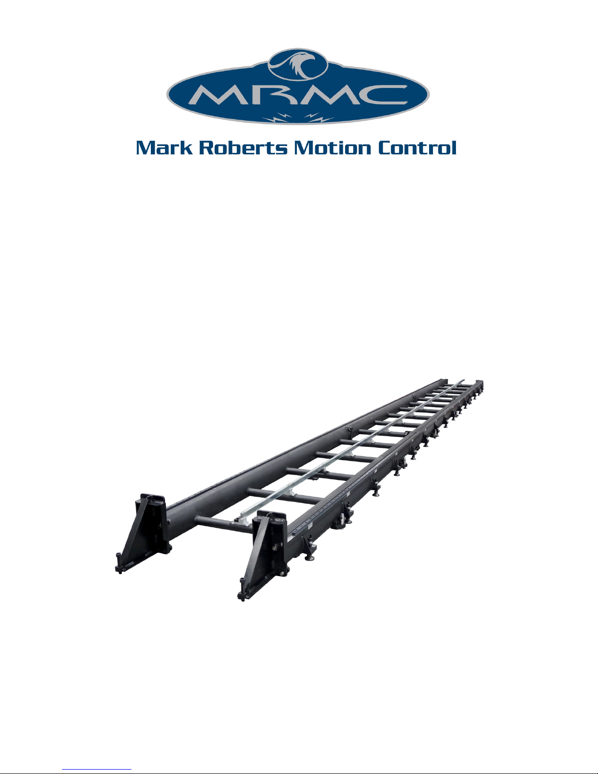
Precision
Track
Quick Start Guide
Document version: TRKPRC-QSG-20160209
Part number: MRMC-1182-04
Page 2

ii
Precision Track Quick Start Guide
Document version: TRKPRC-QSG-20160209
Part number: MRMC-1182-04
© 2016 Mark Roberts Motion Control Ltd. All rights reserved.
No part of this publication may be reproduced, transmitted, or translated
by any means — graphical, electronic, or mechanical — including
photocopying, recording, taping, or storage in an information retrieval
system, without the express written permission of Mark Roberts Motion
Control.
Although every care has been taken to ensure that the information in this
document is accurate and up to date, Mark Roberts Motion Control
continuously strives to improve their products and may make changes to
the hardware, firmware, and software described in this document. Mark
Roberts Motion Control therefore cannot be held responsible for any
error or omission in this document.
All product names mentioned herein are the trademarks or registered
trademarks of their respective owners.
Contact information
Mark Roberts Motion Control Ltd.
Unit 3, South East Studios
Blindley Heath
Surrey
RH7 6JP
United Kingdom
Telephone: +44 (0) 1342 838000
E-mail: [email protected] (sales and general enquiries)
[email protected] (customer support)
Web: www.mrmoco.com
www.mrmocorentals.com
Page 3

Precision Track Quick Start Guide
iii
Precision Track Quick Start GuidePrecision TrackQuick Start Guide
Contents
Chapter 1 Assembling the track .....................................................1
Safety........................................................................................ 1
Overview .................................................................................1
Before you start.............................................................1
Laying the first track section ................................................ 4
Anchoring the track...............................................................6
Laying subsequent track sections.........................................8
Mounting the rack ...............................................................10
Mounting the bearing rail joints ........................................12
Mounting Bolt on the track ................................................14
Mounting Bolt on the track bearings.......................14
Attaching the track motor pinch wheel to Bolt
On Track ......................................................................16
Mounting the bumpers on Bolt On Track...............17
Removing the trolley wheels from Bolt On
Track.............................................................................18
Mounting a Milo or Titan on the track.............................20
Mounting outriggers on the track ............................20
Mounting a Milo or Titan on the track
bearings........................................................................21
Attaching the track motor pinch wheel to a
Milo or Titan...............................................................24
Mounting the bumpers on a Milo or Titan.............25
Mounting the Limit Switch and Datum Switch
magnets on the rack.............................................................27
About track limits.......................................................27
Mounting the magnets ...............................................28
Mounting the weight wings and mechanical limits.........30
Mounting the mechanical limits without weights ...........32
Appendix 1 Specifications............................................................... 33
Page 4

Precision Track Quick Start Guide
iv
Page 5

Precision Track Quick Start Guide
1
Precision Track Quick Start GuidePrecision TrackQuick Start Guide
Chapter 1 Assembling the track
Safety
• Due to the size and weight of track sections, it is recommended that
you use at least two people to assemble it.
• Motion control rigs have powerful motors that can injure, so take
care not to get near the rig while it is switched on.
• Do not step over the track when the rig is switched on — walk
around it instead.
Overview
Thank you for using Precision Track from Mark Roberts Motion Control
(MRMC). The track is designed to help you achieve pixel-perfect
repeatability of your camera moves by supplying smooth, rigid support
when using large, heavy motion control robots such as the Milo, Titan,
and Bolt over long distances.
Before you start
When deciding on the location and orientation of the track, keep in mind
the following important points:
Before laying the track, assess the site to see how level and
firm the ground or floor is. You might need to use boards,
bricks, or crates to create a level surface or stop the track feet
sinking into soft ground. If you will be laying more than two
track sections on a reasonably level floor, laying the middle
section first and working outward can help prevent any
unevenness of the floor from accumulating from section to
section, beyond the ability of the track height adjustment range
Page 6
Precision Track Quick Start Guide
2
to cope. Beyond this range you will need to use additional
supports to keep the track flat and level.
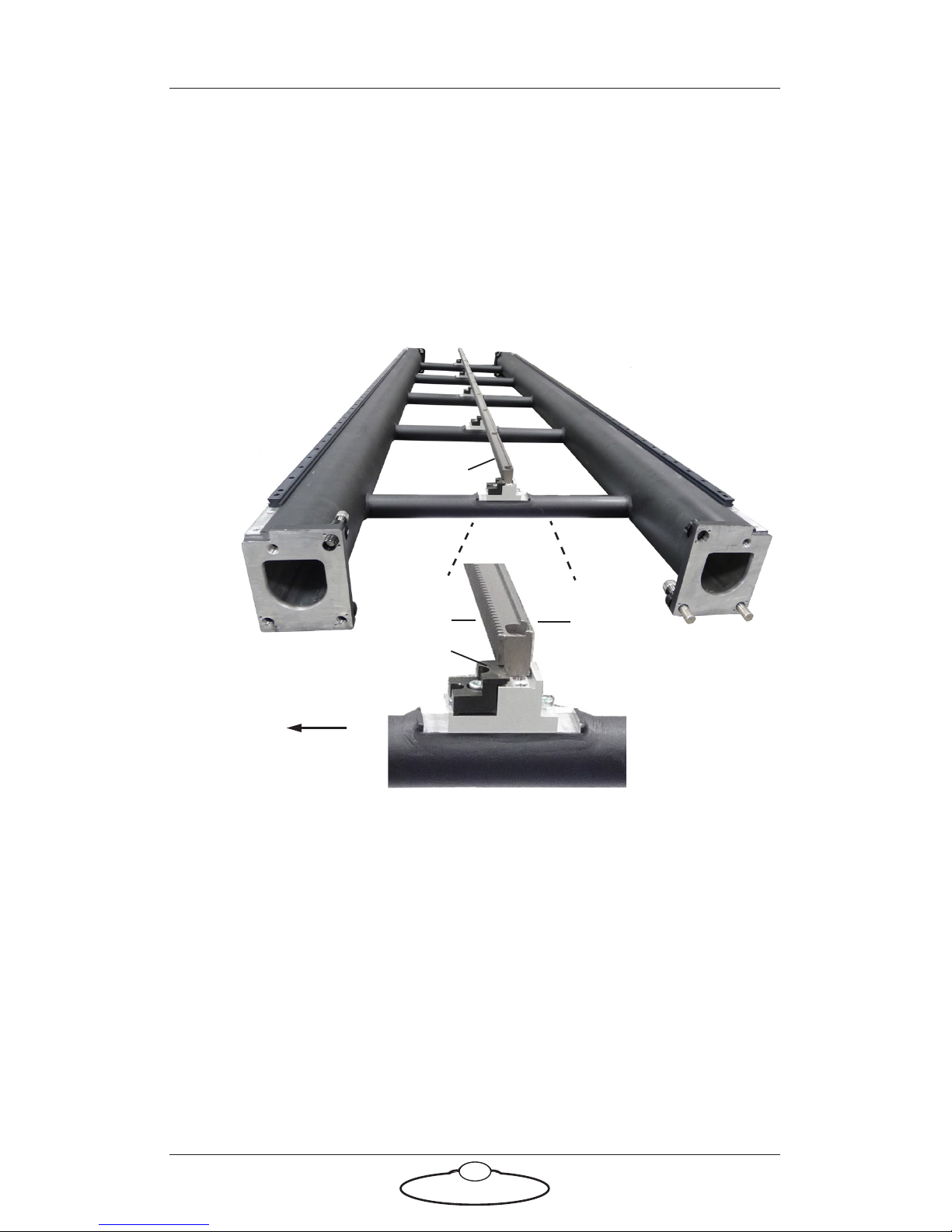
The track is not reversible due to the rack, which has teeth on
one side. You must lay all sections the same way around. If
your track does not have the rack installed yet, look at the rack
clips on the track, which will grip the rail on the teeth side
when you install the rail later.
Some rigs have a sense of Forward and Reverse on the track. A
Bolt High-Speed Cine-bot, for example, executes moves going
Forward. Because its track motor gear is on the front left
underside of the rig, the teeth of the rack are on the left side as
you look in the Forward direction down the track.
Keep in mind where the umbilical cable comes out on the rig
(if this is important for your shot) and whether you can change
it by re-routing the cables on the rig. For example the umbilical
cable on Bolt comes out on the same side of the track as the
track motor gear (which is the same side as the rack teeth).
Umbilical side
Clip
Te e t h
Smooth
Rack
View looking
“Forward” down the
track with the gear
teeth on the left:
Page 7
Precision Track Quick Start Guide
3
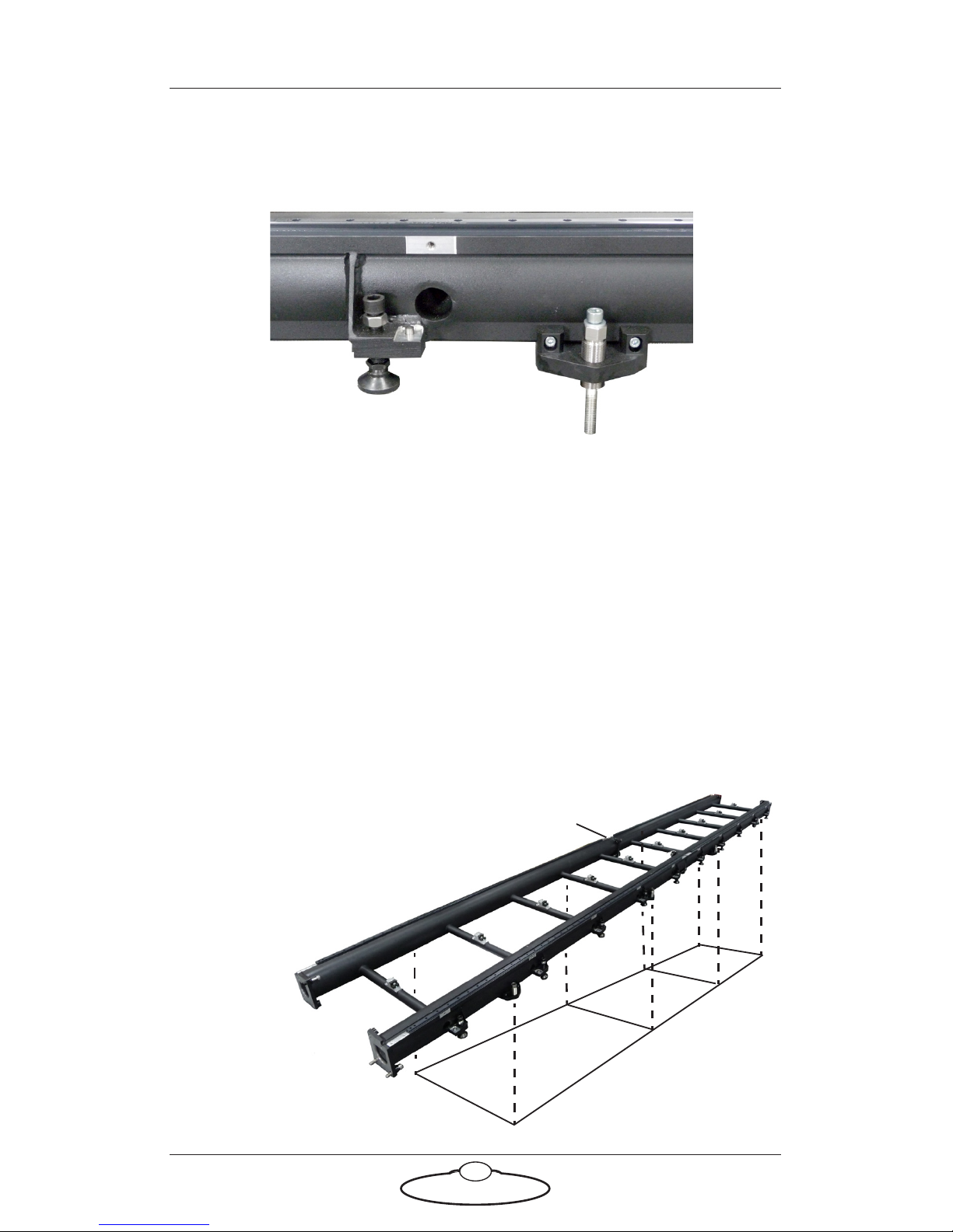
Each Precision track section has ten feet for supporting and
levelling the track, and four anchor brackets for holding the
track down if you are using a high-speed rig such as Bolt.
If you are using a fast rig such as Bolt On Track then you must
hold the track down. You can either anchor the track to the
floor to get the best repeatable stability (page 6), or if this is not
feasible you can use weights on the ends of the track to give
you the safety margin that you need to perform the shoot (page
30). Anchoring the track to a concrete floor involves drilling
holes in the floor. If the floor is wood you can screw directly
into it. The anchor hole spacing is shown below but it is more
accurate to drill through the anchor brackets once the track is
in place using the procedures later in this guide.
Foot, which takes the
weight of the track and
rig
Anchor bracket, which
holds the track down
on the ground.
Joint
873
1562
1562
1429
millimetres:
Page 8
Precision Track Quick Start Guide
4
Laying the first track section
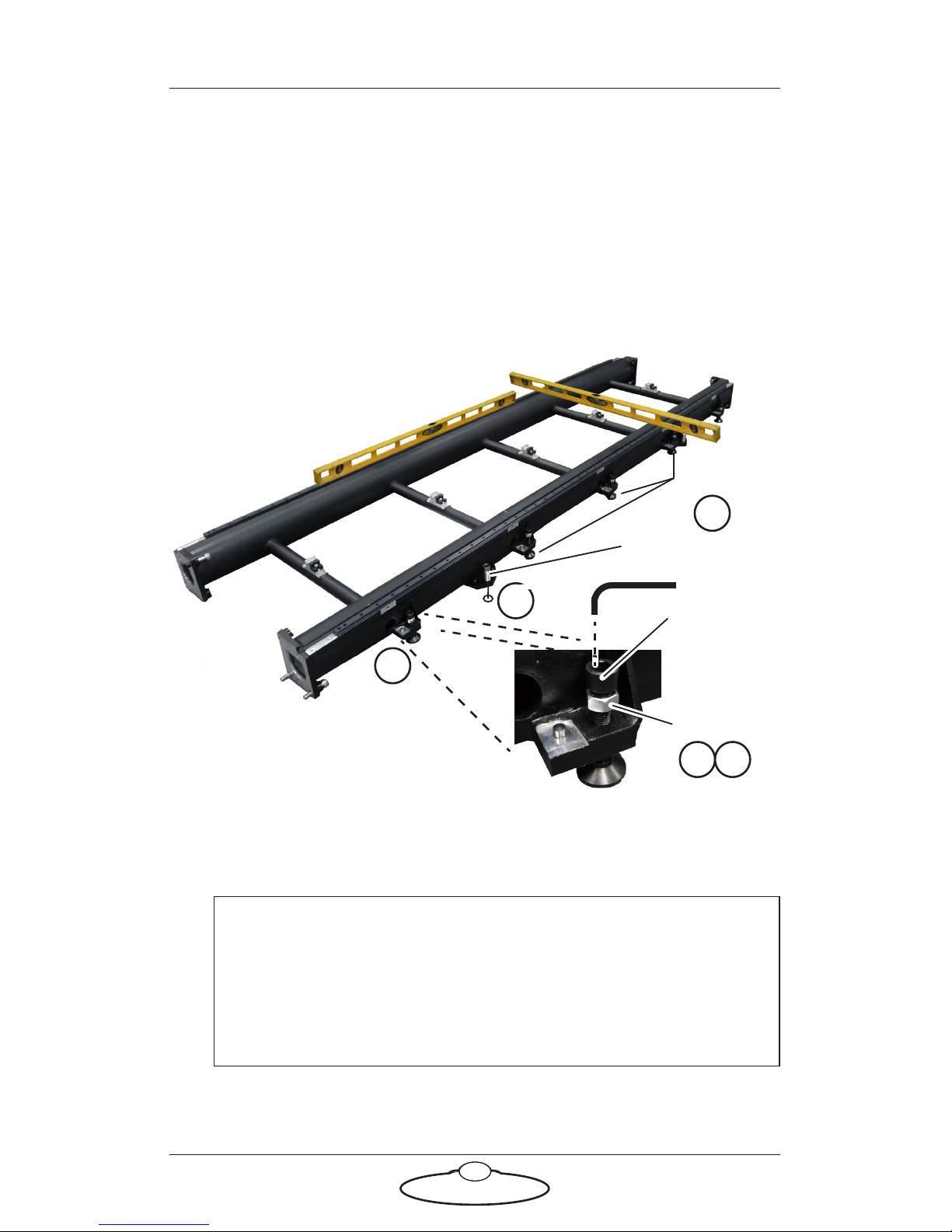
1. Lay the first track section on the ground, on its feet.
2. If you will be using a fast rig such as Bolt and the floor already has
anchor holes from a previous installation then you would obviously
put the track anchor brackets over the existing holes.
3. Raise the six middle feet of the track section (three on each rail) and
the four threaded anchor sleeves so they do not touch the ground.
4. Level the track in both length and width directions using a spirit
level, by adjusting the four corner feet of the track. Make sure all
four corner feet are touching the ground (no wobble).
5. Tighten the lock nuts down against the track on the corner feet,
being careful not to change the height.
Hint
The four corner feet also determine the track height. If you are
laying track on a level floor, try to use the middle of the height
adjustment range so that subsequent sections have some leeway
(in their feet) to cater for any unevenness in the floor.
Lock nut
4
Height
adjustment
bolt
2
5
Middle feet
Anchor sleeve
3
6
Page 9

Precision Track Quick Start Guide
5
6. Lower the six middle feet until they touch the ground (finger tight
against the ground) and then tighten the lock nuts on them.
Page 10
Precision Track Quick Start Guide
6
Anchoring the track
If you are using a fast rig such as Bolt On Track you must either hold the
track down with weights (see page 30) or secure the track to the floor by
using bolts or screws through the four track anchor brackets. Anchoring
the track to the floor gives you more repeatable stability than using
weights. The following procedure tells you how to anchor the track to a
concrete floor.
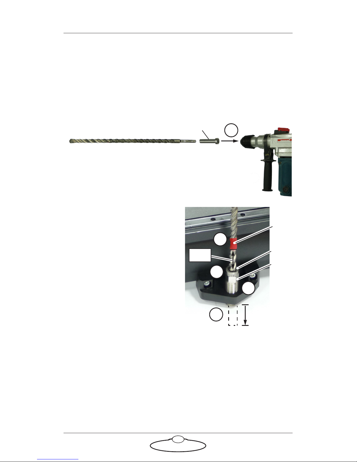
2. On one of the track anchor
brackets, screw the sleeve all
the way down to the floor,
finger tight.
3. Insert the drill bit and guide
into the threaded sleeve on the
anchor bracket, so the drill bit
is against the floor.
4. Put tape around the drill bit 5
cm above the guide. This will
help you gauge the depth of the
hole in the next step.
5. Drill a hole 5 cm deep into the
concrete. When the tape reaches the top of the guide, drilling is
complete.
6. Remove the drill bit and guide from the sleeve and clean the hole.
1. Put the drill bit into the drill guide and attach
the bit to the drill. (The cutting end of the bit is
too large to fit through the guide, so you must
insert the other end into the guide, then into
the drill.)
1
Guide
15 mm drill bit
Guide
Sleeve
2
3
5 cm
Ta pe
4
5 cm
4
5
Page 11
Precision Track Quick Start Guide
7
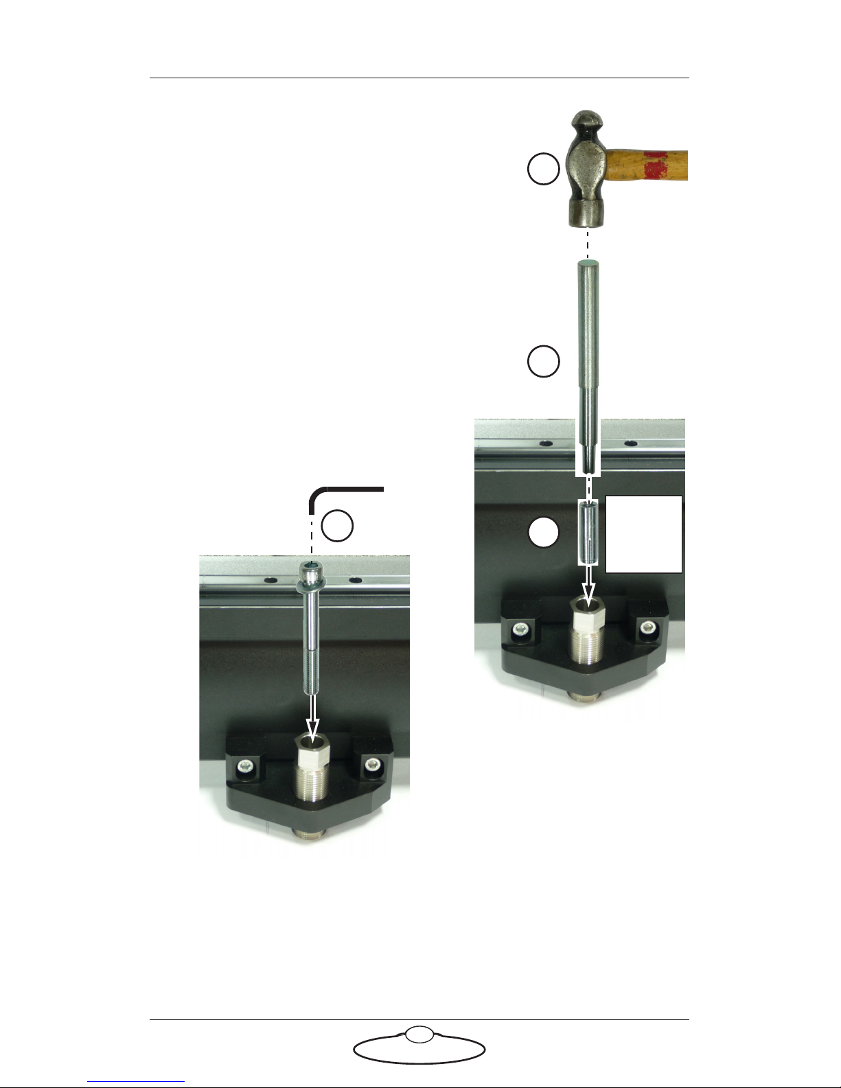
7. Put the drop-in anchor insert,
threads upward, through the sleeve
and into the hole in the concrete, all
the way to the bottom.
8. Insert the anchor spreader tool into
the drop-in anchor insert.
9. Hit the top of the anchor spreader
tool with a hammer until the anchor
is fully spread in the concrete, being
careful not to hit the track.
10. Remove the anchor spreader tool.
11. With the sleeve still finger-tight
against the floor, insert the retaining
bolt through the sleeve and into the
drop-in anchor insert, and tighten.
12. Repeat steps 2 to 11 for the other three anchor brackets on the track
section.
7
Anchor
spreader
tool
Drop-in
anchor
insert
8
9
11
Page 12
Precision Track Quick Start Guide
8
Laying subsequent track sections
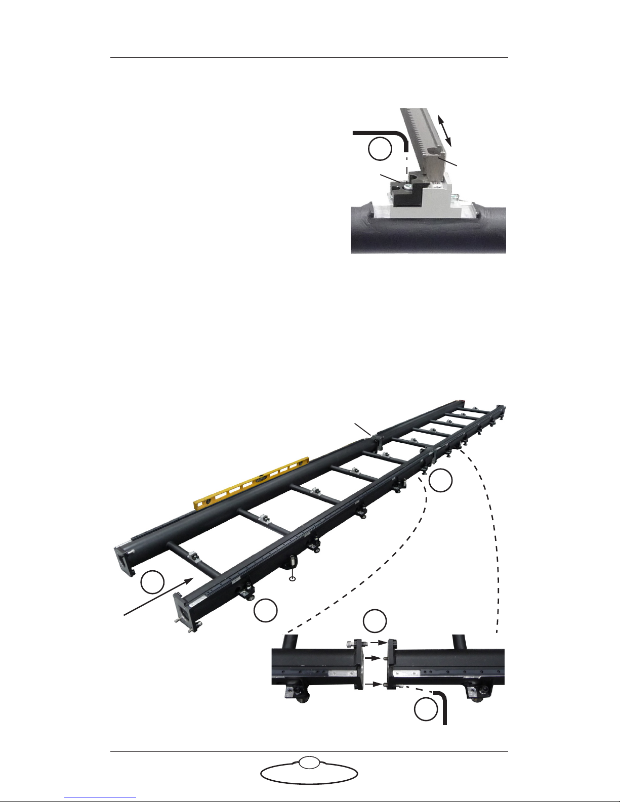
1. If any of your track sections already
have a rack installed, loosen the rack
clips so you can temporarily slide the
rack along the track and out of the
way when you are joining the track
sections.
2. Lay the next track section in line
with the previously laid track section
and as close to it as possible, making
sure it is the right way around (see
the notes on page 2).
Again, if you will be using a fast rig such as Bolt and the floor
already has anchor points from a previous installation, put the track
anchors as close as possible to the existing holes.
3. Raise the middle feet and anchor sleeves of the new track section so
they do not touch the ground.
1
Clip
Rack
Section 1
Section 2
4
5
6
6
Joint
7
Joint
Page 13

Precision Track Quick Start Guide
9
4. Adjust the height of the new track section to match that of the
previous section by adjusting the two corner feet nearest to the joint
(one on each rail).
5. Level the new track section with a spirit level by adjusting the two
corner feet furthest from the joint (one on each rail).
6. Slide the new track section along the floor against the previous track
to firmly engage the ends of the rails. (Slide the new section — not
the previous section.)
You might need to repeat steps 4 to 6 until you get good alignment
of the rails at the joint.
7. Firmly tighten the six large bolts that hold the track sections
together at the joint (three on each rail). You can also use these to
help pull the track sections together, once they are at the same
height.
8. On the new track section, tighten the lock nuts down against the
track on the four corner feet.
9. On the new section, lower the six middle feet until they touch the
ground (finger tight against the ground) and then tighten the lock
nuts on them.
10. If you are using a fast rig such as Bolt anchor the new track section
to the floor as you did for the previous track section, using the
procedures in Anchoring the track on page 6.
Repeat steps 1 to 10 in this section to lay additional sections of track.
Page 14
Precision Track Quick Start Guide
10
Mounting the rack
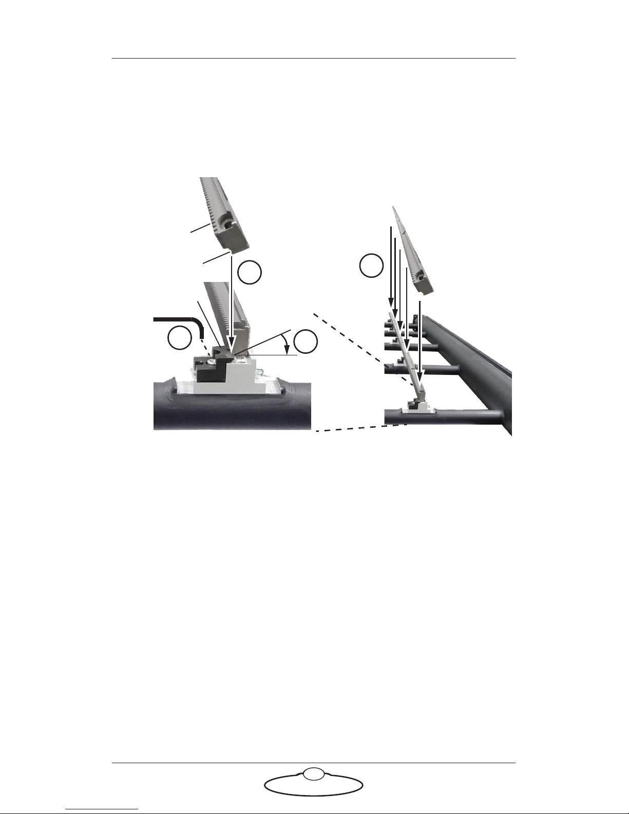
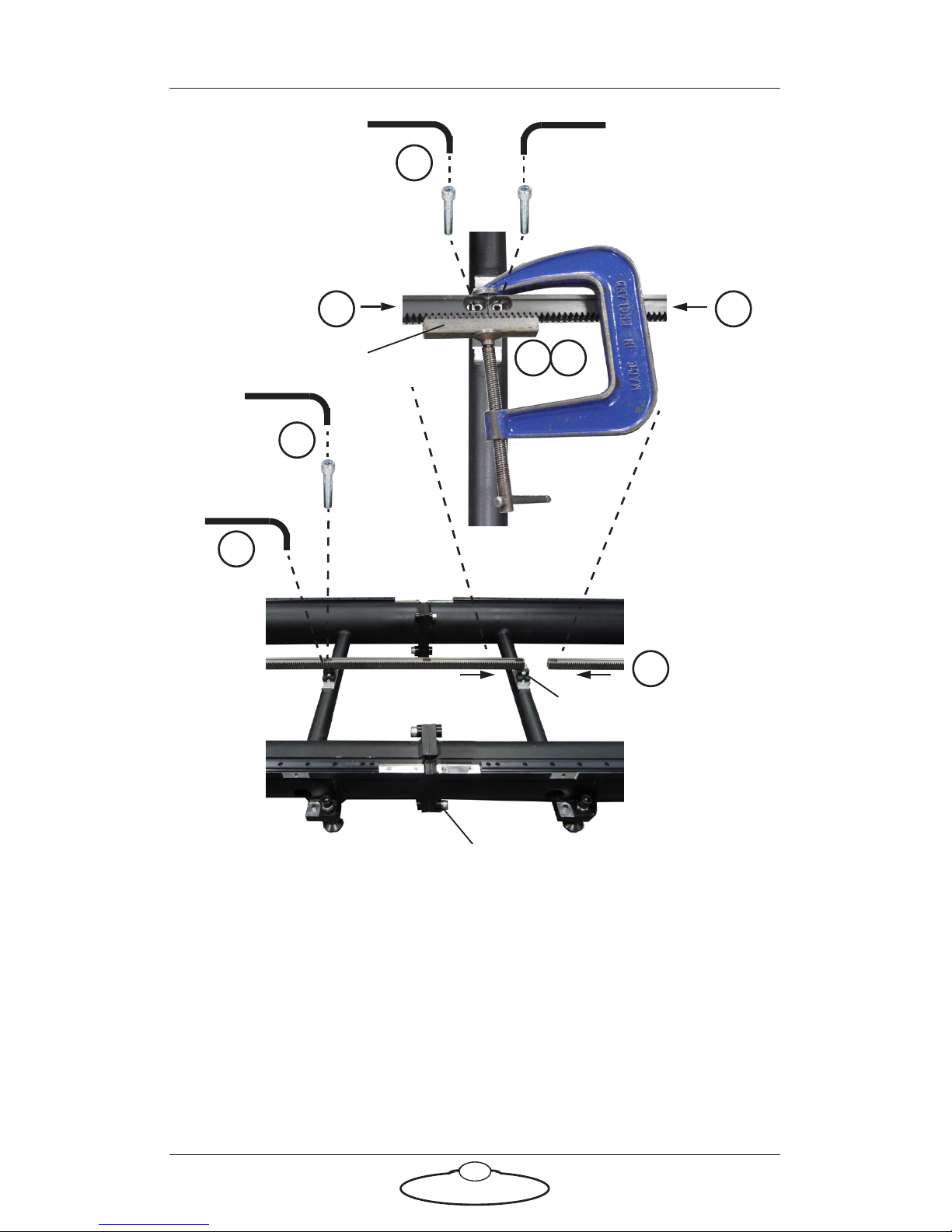
1. If your track sections do not yet have the racks mounted on them,
do this now for each track section as follows:
1.1 Loosen all the rack clips on the track section.
1.2 Lay the rack into the brackets on the track, tilted as shown,
making sure that the clips on the track go into the groove on
the rack, just under the teeth.
1.3 Twist the rack to lay flat in the brackets. Do not tighten the
clips yet.
1.4 Repeat steps 1.1 to 1.3 for each track section.
2. In the middle of the track, slide two of the racks together
end-to-end, so that the joint between them is centred over one of the
rack mounting brackets near the main rail joint.
3. Make sure the rack joint has the correct spacing by clamping a rack
matching block to it, teeth meshed, using a vice.
4. Insert the two retaining bolts through the ends of the racks and into
the mounting bracket (one on each side of the joint), and tighten.
5. Remove the vice and rack matching block.
1.1
Groove
Te e t h
1.2
1.3
1.2
Clip
Page 15
Precision Track Quick Start Guide
11
6. Tighten all rack clips on the two adjoining sections of track.
7. If you are using a high-speed rig such as Bolt, also secure the rack
with an extra bolt through the rack at every mounting bracket. This
is not usually necessary for slower standard rigs.
8. Repeat steps 1 to 7 to mount the rack on all remaining sections of
track, working outwards from the centre track section.
Main rail joint
Rack mounting bracket
2
3
4
6
22
7
Rack matching block
5
Page 16
Precision Track Quick Start Guide
12
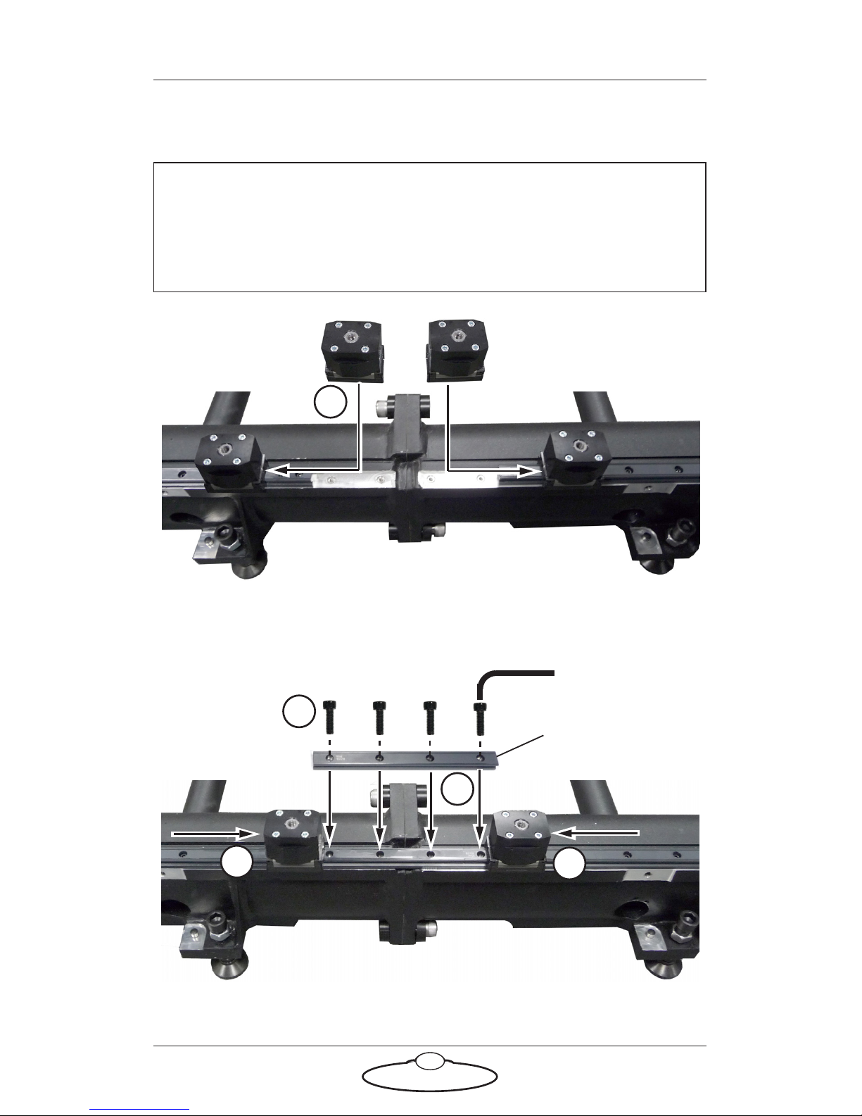
Mounting the bearing rail joints
1. At one of the track joints, slide two track bearings over the ends of
the bearing rails.
2. Put one of the long bearing rail joints onto the track.
Hint
Always mount and remove the track bearings with care. Try to keep
them squared up and in-line with the bearing rail to avoid damaging
them or loosing a bearing.
1
Track bearing
Track joint
2
3
4
3
Bearing rail joint
Page 17

Precision Track Quick Start Guide
13
3. Align the bearing rail joint with the existing rail by sliding the track
bearings partially over the joint at each end.
4. Insert the bolts and tighten them.
5. Slide the track bearings along the rail to the next joint and repeat
steps 1 to 4 for all remaining joints. For the track ends you use the
short bearing rail pieces (with only two holes) and only one track
bearing to help with alignment.
Page 18
Precision Track Quick Start Guide
14
Mounting Bolt on the track
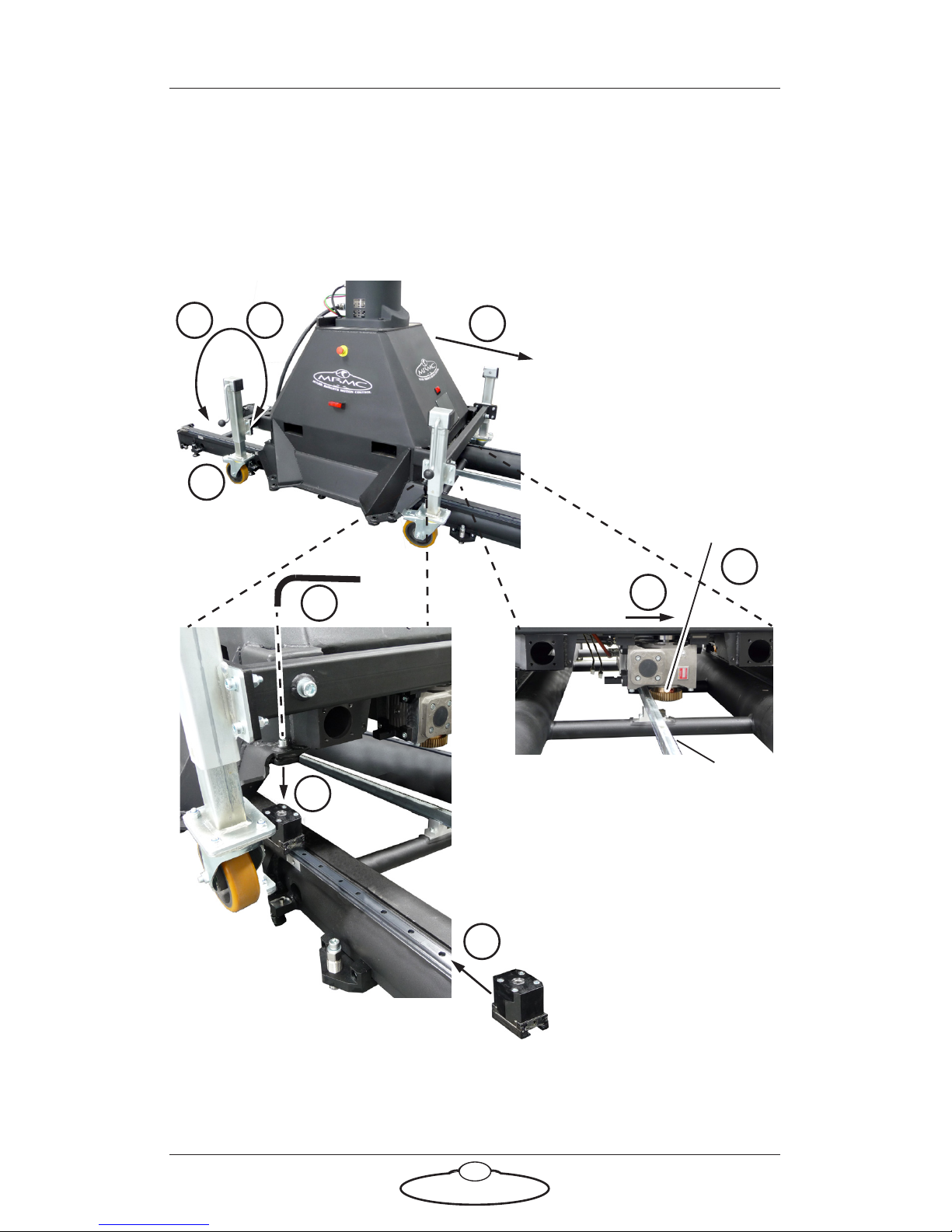
This section tells you how to mount Bolt On Track onto Precision Track.
Mounting Bolt on the track bearings
4
5
6
Te e t h
3
R
ac
k
Track
motor
gear
7
5 1
1
2
Page 19

Precision Track Quick Start Guide
15
1. Roll the rig to a position just off the end of the track, raise the rig on
its wheels high enough to go over the track using the wheel cranks,
and rotate the rig on its wheels to be the correct way around so that
the track motor gear on the rig underside is on the toothed side of
the rack. Do not engage the teeth yet; just make sure the rig is the
correct way around for the track.
2. On the underside of the rig, remove the pinch wheel if you haven’t
already done so and push the track motor out of the way on its
sliding bearings, so that the track motor gear will not interfere with
the Rack on the track. (For details of removing the pinch wheel,
follow the procedure on page 16 in reverse order.)
3. Push the rig on its wheels over the track about a metre, being careful
not to push the track motor gear against the rack while moving.
4. Push the four track bearings onto the ends of the track (two on each
rail) and into position under the four corners of the rig base.
5. Carefully lower the rig onto the four track bearings, making sure
that all four bearings are aligned with the corners of the rig base,
and the track motor gear on the underside of the rig clears the rack.
6. Tighten the four track bearing mounting bolts at the corners.
7. Apply the brakes to the wheels to keep them from pivoting against
the track (the brakes affect both rotation and pivot), and raise the
wheels off the ground so the full rig weight is taken by the track.
8. Feed out enough umbilical cable from your control area to reach the
entire length of the track without stretching the cable. Make sure the
area alongside the track is clear so that the umbilical cable doesn’t
catch on anything when the rig drags it alongside the track.
9. Attach the track motor pinch wheel on the underside of the rig,
described in Attaching the track motor pinch wheel to Bolt On Track
on page 16.
Page 20
Precision Track Quick Start Guide
16
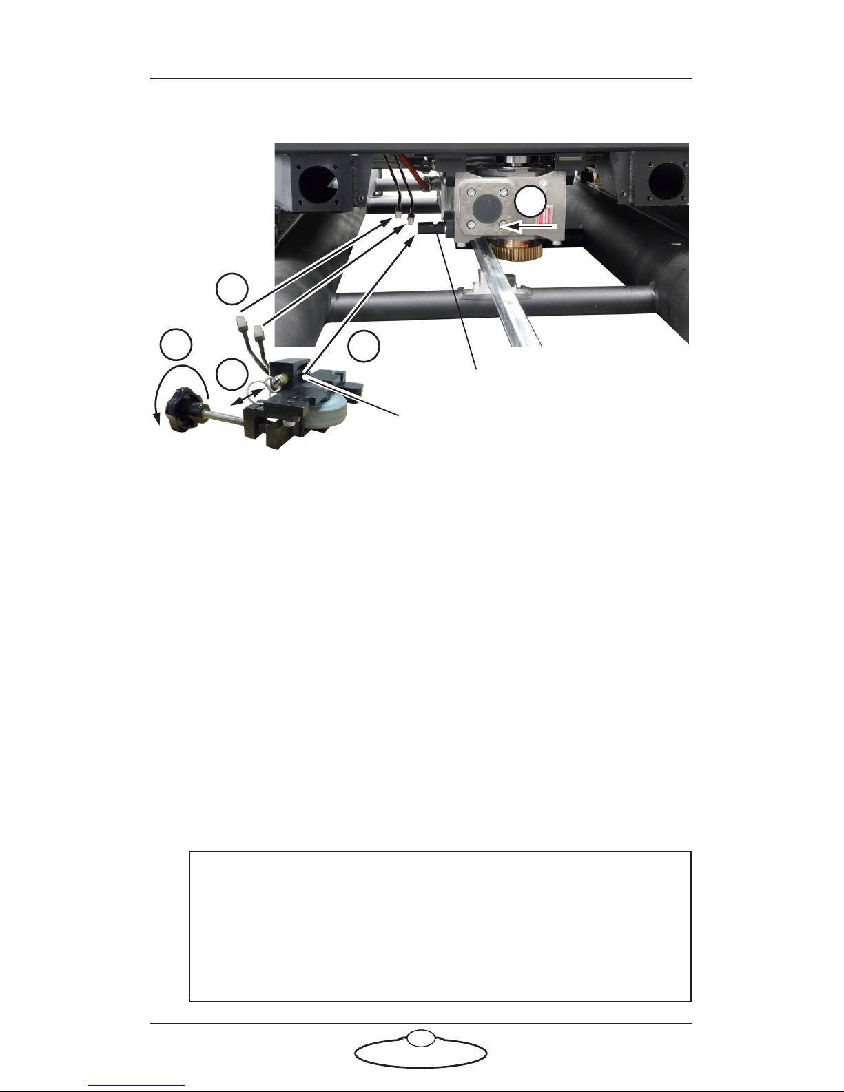
Attaching the track motor pinch wheel to Bolt On Track
1. On the separately supplied pinch wheel assembly, remove the brass
retaining pin by pulling on the ring.
2. Mount the pinch wheel assembly onto the track motor on the rig
underside, by sliding the track motor gear against the rack and
putting the pinch wheel Socket onto the track motor Mounting bar.
3. Replace the retaining pin in the pinch wheel assembly by pushing on
the ring (not the sleeve), to hold the assembly in place on the track
motor.
4. Hand-tighten the pinch wheel adjustment bolt so that the rubber
wheel presses firmly against the smooth side of the rack. This holds
the track motor gear firmly against toothed side of the rack.
5. Connect the pinch wheel cables for the Limit Switch and Datum
Switch to their corresponding connectors (usually labelled L and D)
on the rig underside, and use cable ties to hold them securely up
away from the track.
Hint
The Limits and Datum magnets on the track are physically
swappable (see page 28). Make sure you connect the Limit cable
from the rig to the pinch wheel switch that is over the Limit
magnet position on the track, and ditto for the Datum cable.
Mounting bar
1
2
5
4
Socket
2
Page 21
Precision Track Quick Start Guide
17
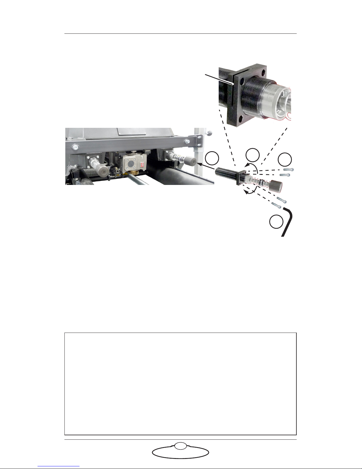
Mounting the bumpers on Bolt On Track
1. Insert one of the bumpers into the hole in the base of the rig.
2. Insert the four retaining bolts through the bumper bracket and into
the base, but do not tighten yet.
3. If you want, adjust how far the bumper extends from the rig by
screwing it in or out of its threaded bracket.
4. Tighten the four retaining bolts on the bumper.
5. Repeat steps 1 to 4 to mount the other three bumpers.
Hint
One of the corners on the bumper bracket has a locking slot cut into
it. Tightening the bolt on this corner flexes the bracket, which in turn
locks the threaded cylinder of the bumper to prevent it from turning.
To adjust the amount of bumper extension after the bumper is
mounted you only need to loosen the bolt on the bracket corner with
the locking slot. You can then turn the bumper in its bracket to
adjust the amount of extension, and re-tighten the bolt when you
have finished.
Locking slot
1
2
3
4
Page 22
Precision Track Quick Start Guide
18
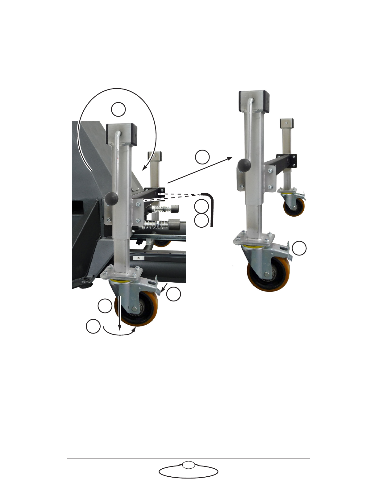
Removing the trolley wheels from Bolt On Track
After mounting the rig on the track you can remove the two trolley wheel
units that are on either side of the rig.
1. With the base of the rig supported by the track, pivot the wheels
away from the rig.
2. Turn the cranks to lower the wheels to the ground.
3. Apply the wheel brakes.
4. Remove the two bolts holding the wheel trolley unit on the rig.
5. Lift the wheel unit away from the rig.
6. Insert the two wheel trolley retaining bolts back into the rig base, for
safe keeping.
1
2
3
4
5
2
7
6
Page 23

Precision Track Quick Start Guide
19
7. If you are going to store the wheels for weeks or months, release the
wheel brakes so they don’t leave a dent in the wheel rubber.
Page 24
Precision Track Quick Start Guide
20
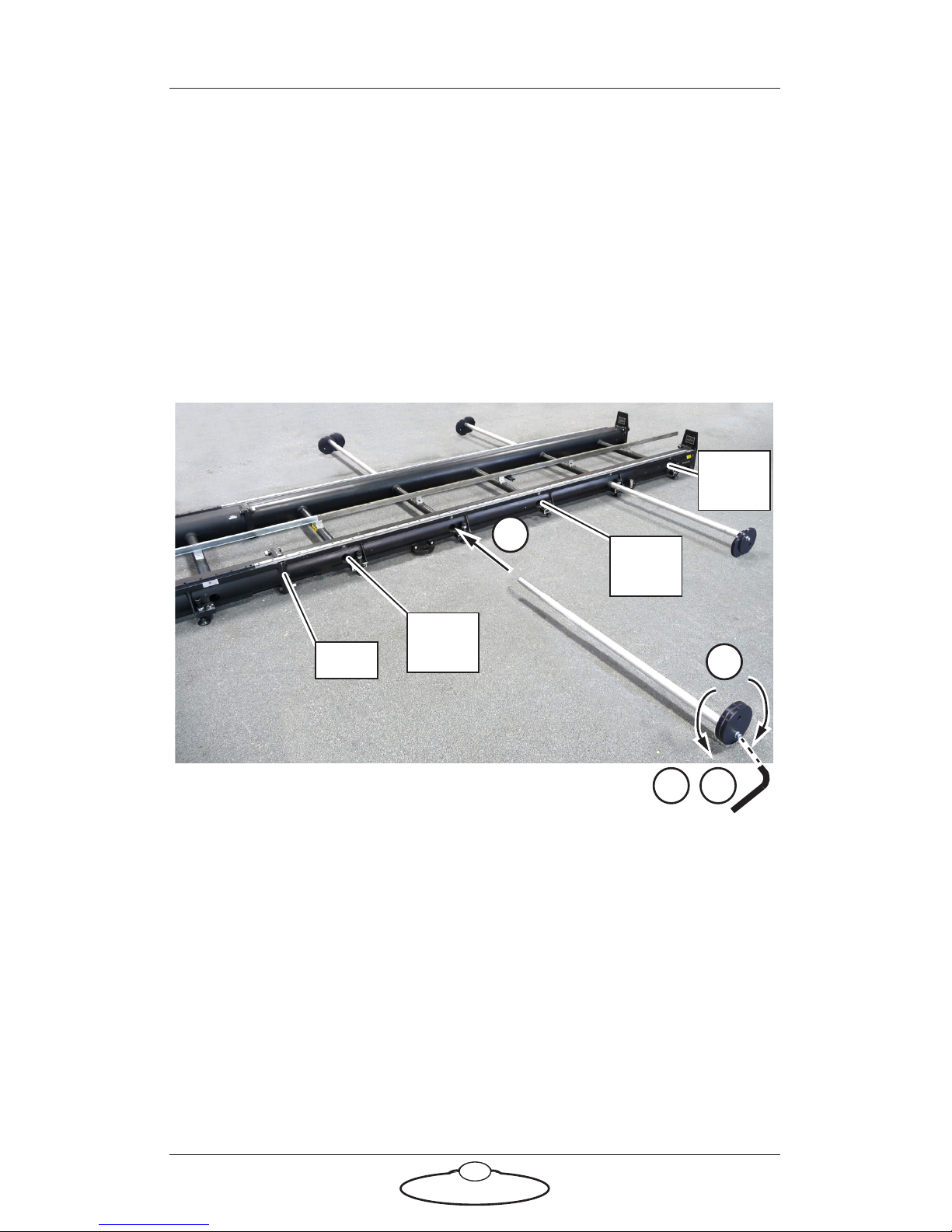
Mounting a Milo or Titan on the track
Mounting outriggers on the track
The outriggers for Precision Track are a safety feature that prevents the rig
tipping when assembling or using a Milo Long Arm or Titan. Although
these rigs are balanced when assembled properly, the rig can be off
balance temporarily during assembly or disassembly, or when performing
a large acceleration or emergency stop that produces sudden rotational
force directed over the track. You install four outriggers in each section of
track. Leave the centre hole and end holes empty.
1. Insert the outrigger into an appropriate hole in the side of the track
as far as it will go — this is about 340 mm, or about twice the length
of the shiny tip of the outrigger.
2. Loosen the bolt on the end of the outrigger to allow the off-centre
disks to rotate on the shaft.
3. Rotate the off-centre discs on the shaft in opposite directions until
they both press against the floor, hand tight.
4. Re-tighten the bolt.
5. Repeat for the other three outriggers for the section, and for each
section of track.
1
3
Joint
Leave
empty
Leave
empty
Leave
empty
2 4
Page 25
Precision Track Quick Start Guide
21
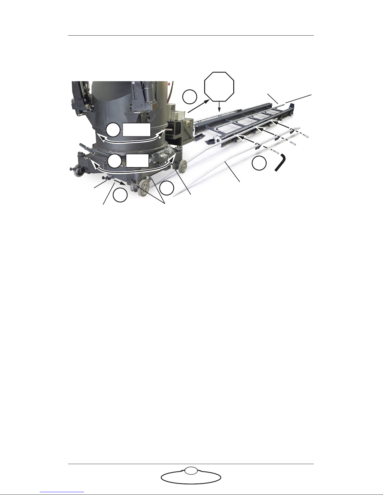
Mounting a Milo or Titan on the track bearings
1. Attach the pair of ramp-up rails to one end of the track, using three
bolts on each rail.
2. Roll the rig to a position just off the end of the track, making sure
the base is the correct way around. The track motor gear on the
underside of the rig must be on the toothed side of the Rack.
3. You can rotate the Turret later if you need to point the arm in the
other direction along the track during the shoot. For now, point the
arm parallel to the track to make sure the rig is balanced over the
track.
4. On the underside of the rig, remove the pinch wheel if you haven’t
already done so and push the track motor out of the way on its
sliding bearings, so that the track motor gear will not interfere with
the Rack on the track. (For details of removing the pinch wheel,
follow the procedure on page 24 in reverse order.)
5. Roll the rig on its wheels up the ramp, making sure that the rail
wheels (with concave edges) are centred on the ramp-up rails. Stop
the rig when it is centred over the highest point on the ramp-up
rails, and before the rig reaches the small down-slope at the other
end of the ramp-ups.
6. Apply the brakes.
1
5
4
2
T
e
et
h
S
m
oo
th
side
side
Rack
Pinch
wheel
Track motor gear
Base
Tu r r et
3
Brakes
Ramp-up rail
Stop at
the top
6
Rail wheel
Page 26
Precision Track Quick Start Guide
22
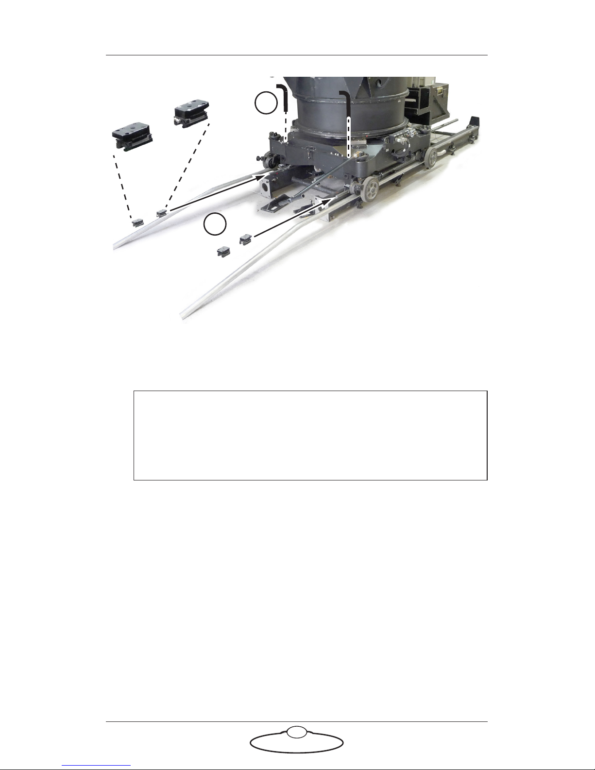
7. With the rig at the highest point on the ramp-up rails, carefully push
the four track bearings onto the ends of the bearing rails (two on
each rail) and into position under the four corners of the rig base.
8. At each corner of the rig, use a hex key to push the captive bolt
down into the track bearing and tighten to make sure the track
bearing is lined up with the corner of the rig. You will not be able to
tighten it completely yet because the rig is still sitting on the
ramp-up rails and not on the track bearings.
9. Under the rig, move the track motor on its sliding bearings so that
the Rack is centred between the track motor gear and the pinch
wheel mount point. The purpose is to make sure that no part of the
rig touches or interferes with the Rack when you push the rig the
rest of the way onto the track in the next step.
Hint
Always mount and remove the track bearings with care. Try to
keep them squared up and in-line with the bearing rail to avoid
damaging them or loosing a bearing.
Track bearings
7
8
Page 27
Precision Track Quick Start Guide
23
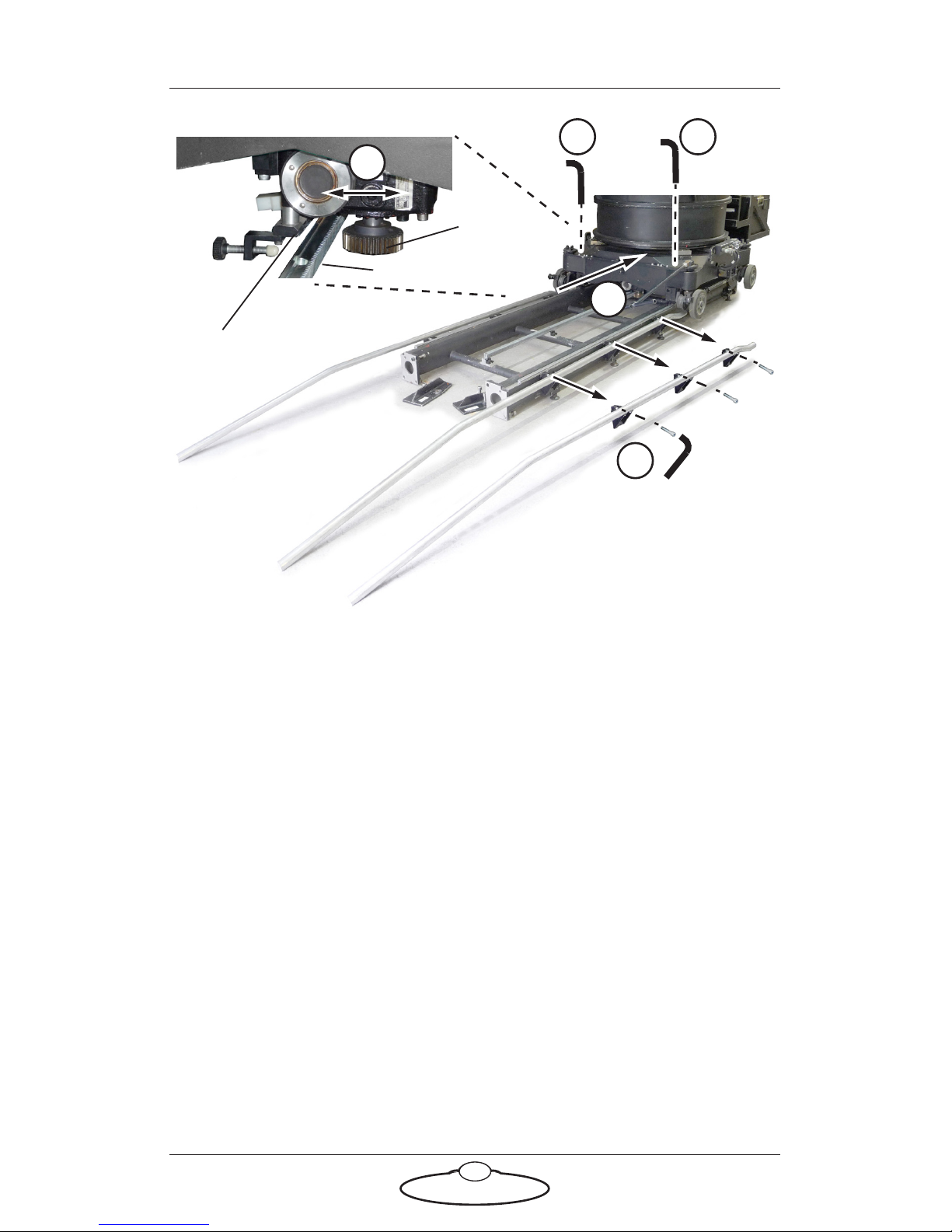
10. Let off the brakes and push the rig further along the ramp, down the
small slope, and the rest of the way onto the track. When you do
this, make sure that each of the four track bearings fits into the
recess at the corners of the rig.
11. Tighten the four track bearing mounting bolts at the corners.
12. Remove the ramp-ups from the track so that the rig has the full run
of the track.
13. Feed out enough umbilical cable from your control area to reach the
entire length of the track without stretching the cable. Make sure the
area alongside the track is clear so that the umbilical cable doesn’t
catch on anything when the rig drags it alongside the track.
14. Attach the track motor pinch wheel on the underside of the rig,
described in Attaching the track motor pinch wheel to a Milo or Titan
on page 24.
R
ac
k
Te e t h
Track
9
10
motor gear
Pinch wheel
mount point
11
12
11
Page 28
Precision Track Quick Start Guide
24
Attaching the track motor pinch wheel to a Milo or Titan
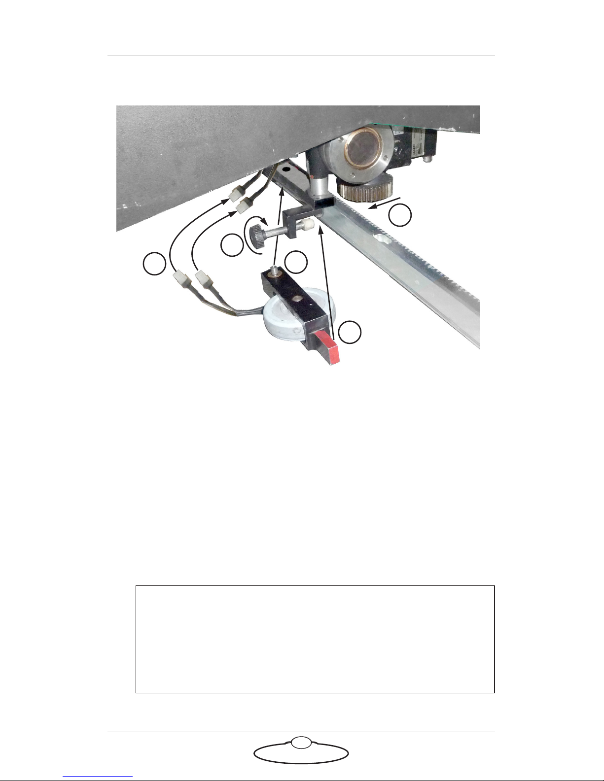
1. On the underside of the rig, slide the track motor gear against the
rack.
2. Bolt the pinch wheel assembly onto the mounting point on the
underside of the track motor and tighten the bolt.
3. Hand-tighten the pinch wheel adjustment bolt so that the rubber
wheel presses firmly against the smooth side of the rack. This holds
the track motor gear firmly against toothed side of the rack.
4. Connect the pinch wheel cables for the Limit Switch and Datum
Switch to their corresponding connectors (usually labelled L and D)
on the rig underside, and use cable ties to hold them securely up
away from the track.
Hint
The Limits and Datum magnets on the track are physically
swappable (see page 28). Make sure you connect the Limit cable
from the rig to the pinch wheel switch that is over the Limit
magnet position on the track, and ditto for the Datum cable.
1
2
3
R
ac
k
4
Pinch wheel assembly
Track motor gear
2
Page 29
Precision Track Quick Start Guide
25
Mounting the bumpers on a Milo or Titan
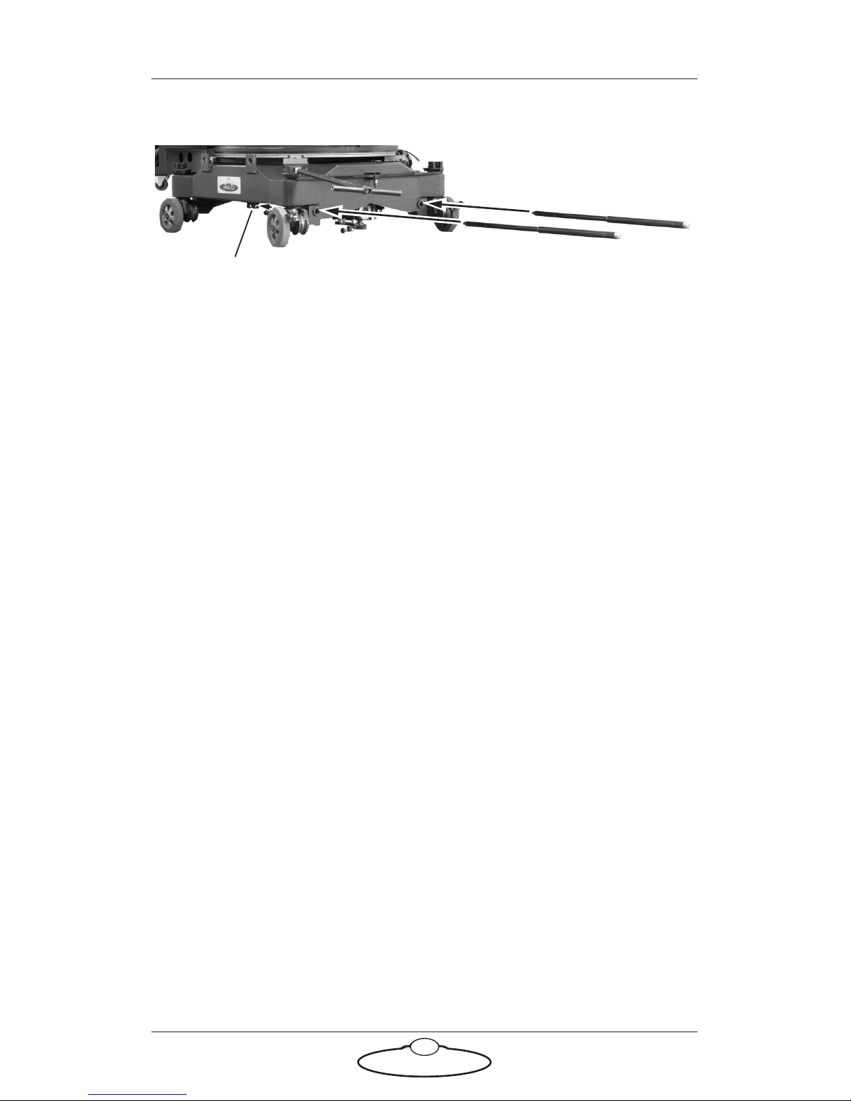
1. Insert one of the bumpers through the appropriate hole in the base
of the Milo or Titan, and then into the mounting bracket until it
clicks into place.
2. Repeat step 1 to mount the other three bumpers at the other three
corners.
Mounting brackets
Page 30

Precision Track Quick Start Guide
26
Notes
Page 31

Precision Track Quick Start Guide
27
Mounting the Limit Switch and Datum Switch
magnets on the rack
About track limits
In a track-mounted rig there are typically three devices for limiting
movement along the track to prevent the rig going off the end of the
track:
Soft limits - You configure these in the Flair Motion Control
Software that controls the rig. When the system is working
correctly the soft limits act as a barrier to other parts of the
software such as programmed moves or live commands, so that
no part of the software can move the rig beyond the soft limits.
Limit and Datum Switches - The Limit Switch consists of a
magnetic sensor located on the track motor pinch wheel on the
underside of the rig, and two magnets which you mount at
each end of the rack. The position of the magnets along the
rack defines the ultimate limits, along the track, for the rig
electronics. You define the soft limits within the range of the
Limit Switch magnets, so that if the soft limits fail for some
reason and the rig reaches one of the Limit Switch magnets, the
system electronics automatically shut down any further
movement and apply the brakes. A similar switch called the
Datum Switch is used in combination with a single Datum
magnet which you also mount on the rack but at a different
distance from it. The Datum Switch defines a fixed reference
point on the track for the electronics. The Flair software can
then use this position as the home position or zero point, from
which all movements and soft limits along the track are
measured.
Mechanical limits - These are steel plates that physically
prevent the rig from going off the end of the track if the
previous two limits fail. Spring-loaded bumpers on the rig help
to prevent damage to the rig or track, but you should never
intentionally use the mechanical limits to stop the rig.
Mounting instructions are in Mounting the mechanical limits
without weights on page 32.
Page 32
Precision Track Quick Start Guide
28
Mounting the magnets
Although you can mount the magnets for the Limit Switch and Datum
Switch on the rack at any time, you ordinarily do this after mounting the
rig on the track so that you can precisely adjust the height of the magnets
relative to the magnet sensors on the pinch wheel on the underside of the
rig.
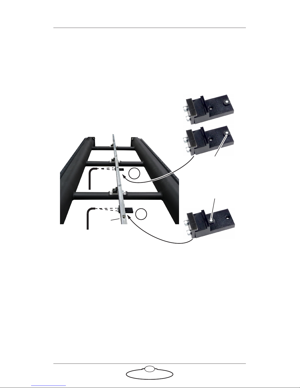
The bracket that holds the magnet has two holes, and there is no
convention regarding which hole to use for the Limit magnets and which
to use for the Datum magnet. Whichever arrangement is used, the two
brackets with an identical arrangement are used for the Limits at the ends
of the track, and the bracket with the magnet in the other hole is used for
the Datum which is between the Limits.
The track motor pinch wheel on the underside of the rig has two switches
(sensors) that run over these two magnet positions — one switch for the
Limits and one for the Datum.
When you install the pinch wheel and connect the rig’s Limit and Datum
cables to the switches on the pinch wheel (page 16 for Bolt or page 24 for
Milo or Titan), you must make sure that you connect the Limit cable to
Limit Switch
magnet
Datum Switch
magnet
End of track
Te e t h
side
2
1
Page 33

Precision Track Quick Start Guide
29
the switch that is in the Limit magnet position, and the Datum cable to
the switch that is in the Datum magnet position.
1. Mount the two Limit Switch magnets (the two brackets that have the
magnet in the same hole) onto the underside of the rack — one at
each end of the track about a metre from the end. The actual
distance depends on your requirements and on which side of the rig
your Limit Switch is on (located on the track motor pinch wheel on
the underside of the rig). Position the magnet along the rack so the
Limit Switch on the pinch wheel goes over the magnet before the rig
hits the physical end of the track with plenty of room to spare.
2. Mount the Datum Switch magnet (the bracket that has the magnet
in the other hole) onto the underside of the rack, usually about 0.2
metres in from one of the Limit Switch magnets depending on your
requirements.
3. Power up the rig and roll it slowly over each magnet, checking for
clearance between the magnet on the rack and the sensor on the
pinch wheel assembly on the underside of the rig. Adjust the height
of the magnet (by loosening and re-tightening the bracket, and
screwing or unscrewing the magnet in the threaded hole) to give 1
to 2 mm of clearance between the magnet and the sensor.
Caution
Mounting the magnets too high can damage them, as they can
come into contact with the pinch wheel assembly on the
underside of the rig.
To adjust the magnet when the rig is over it,
remember to observe safety procedures to
disengage the robot and make use of the E-stops
so that the rig does not move when you are
working under it.
Page 34

Precision Track Quick Start Guide
30
Mounting the weight wings and mechanical limits
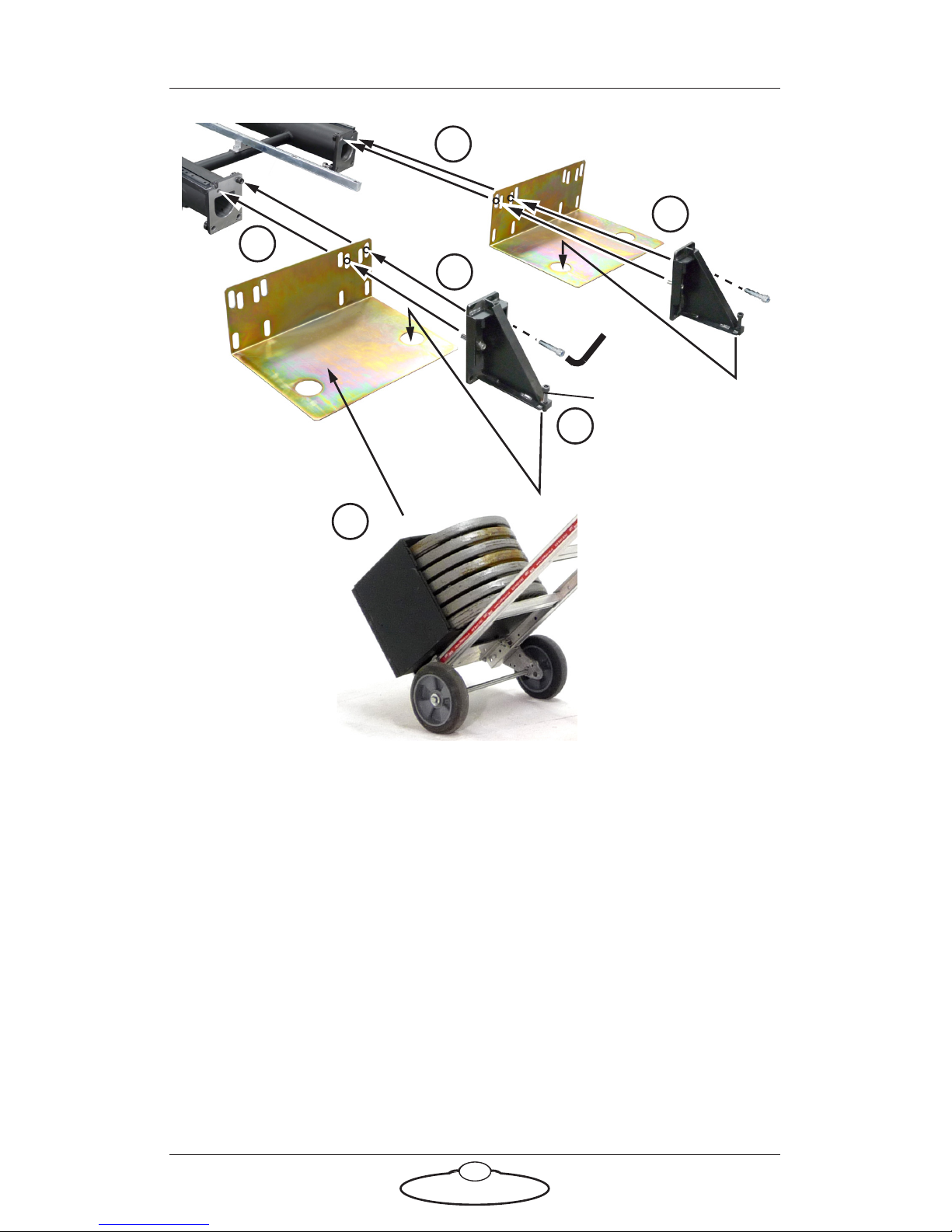
If you are using a fast rig such as Bolt On Track but anchoring the track
into the floor is not feasible, you can alternatively attach optional weight
wings to the ends of the track and hold the track down with weights. The
weight wings fit between the track ends and the mechanical limits.
You ordinarily mount the weight wings and mechanical limits after you
have mounted the rig on the track, although you can mount the rig on the
track later if have a forklift that can lift the rig high enough to go over the
track from the side.
If you are going to mount the rig later, slide the track bearings onto the
bearing rails now, before mounting the weight wings and mechanical
limits. If you forget to do this then when you mount the rig onto the track
you will need to temporarily remove the bearing rail end pieces in order
to get the track bearings onto the bearing rails.
Hint
Using weight wings will not give you the same level of repeatable
stability as anchoring the track to the floor, but will give you enough
stability to operate Bolt On Track safely without tipping the rig over.
Page 35
Precision Track Quick Start Guide
31
1. Put the first weight wing into place on the end of the track, resting
on the floor.
2. Bolt the mechanical limit onto the end of the track, using two bolts
in the upper holes. You might need to remove bolts from the track
joint to make room for the bolts coming through from the
mechanical limit side. Bolts are not necessary at the bottom of the
limits.
3. Screw the foot down against the floor, finger tight only.
4. Put a box of weights onto the wing. Each box contains 140 Kg of
weights (7 × 20 Kg).
5. Repeat steps 1 to 4 for the other three weight wings and mechanical
limits so you have two boxes of weights mounted at each end of the
track.
1
1
Weight wing
2
2
Foot
3
4
Page 36
Precision Track Quick Start Guide
32
Mounting the mechanical limits without weights
You ordinarily mount the mechanical limits after you have mounted the
rig on the track, although you can mount the rig on the track later if have
a forklift that can lift the rig high enough to go over the track from the
side.
If you are going to mount the rig later, slide the track bearings onto the
bearing rails now, before mounting the mechanical limits. If you forget to
do this then when you mount the rig onto the track you will need to
temporarily remove the bearing rail end pieces in order to get the track
bearings onto the bearing rails.
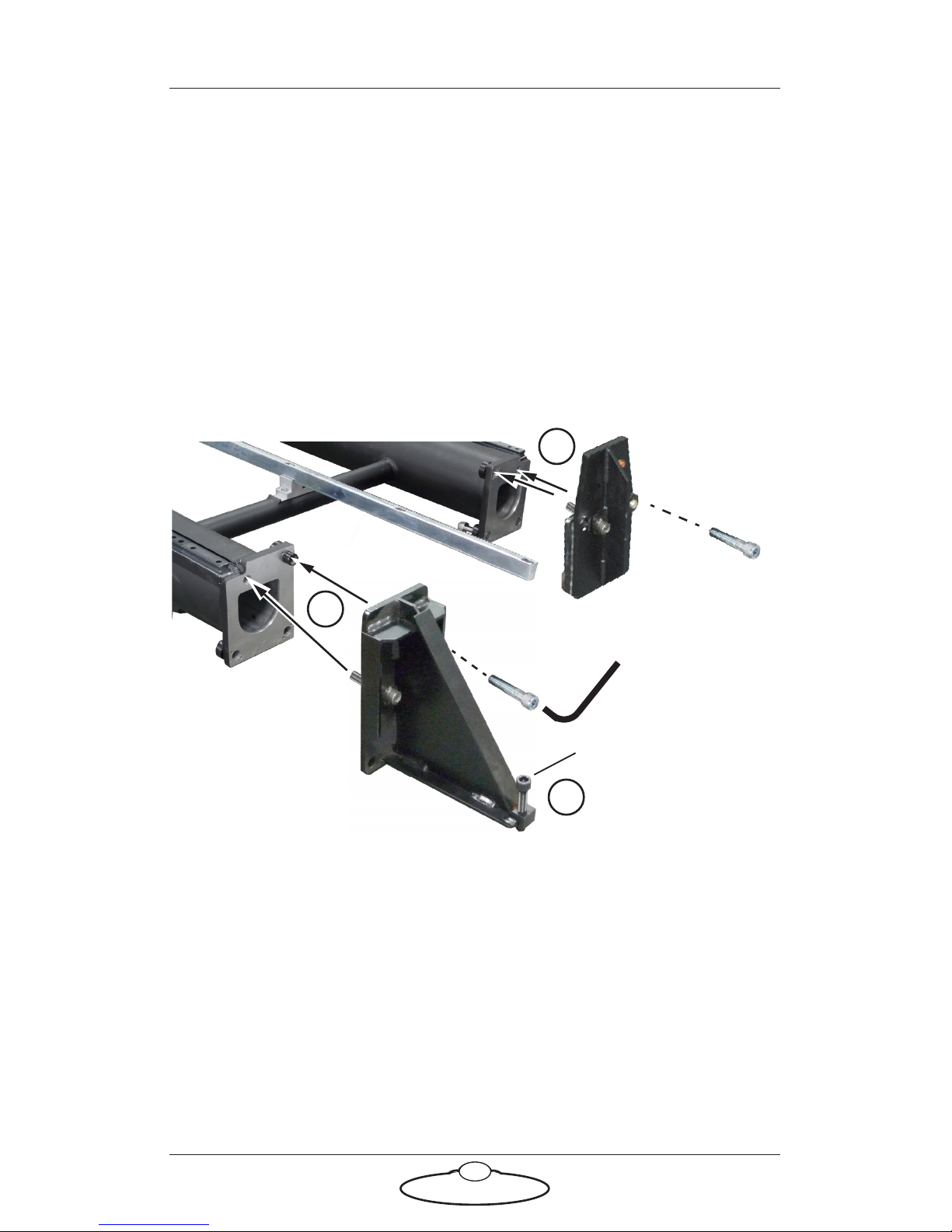
1. Bolt one of the four mechanical limits (end pieces) onto one end of
the track, using two bolts in the upper holes. You might need to
remove bolts from the track joint to make room for the bolts coming
through from the mechanical limit side. Bolts are not necessary at
the bottom of the limits.
2. If you are mounting a limit for a Bolt On Track rig, screw the foot
down against the floor, finger tight only. The limit for a Milo or
Titan rig doesn’t have a foot.
3. Repeat steps 1 to 2 for the other three mechanical limits so you have
two limits mounted at each end of the track.
1
2
Foot
Limit for
a Bolt rig
Limit for a
Milo or Titan
rig
1
Page 37
Precision Track Quick Start Guide
33
Precision Track Quick Start GuidePrecision TrackQuick Start Guide
Appendix 1 Specifications
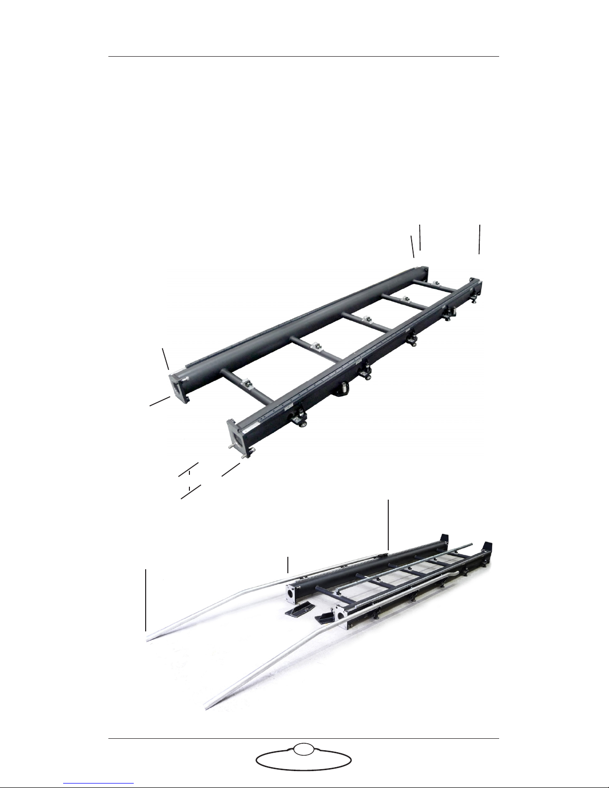
Weight: 95 Kg per section including the rack
21 Kg per pair of ramp-ups
140 Kg for each box of weights 4 boxes if using weight wings.
— 800 —
—
2991
—
—
930
—
195
Bearing rail
spacing
centre-to-centre
Bearing
rail
height
—
1260
—
Ramp-ups for
Milo or Titan
—
1760
—
—
3020
—
Dimensions: All measurements are in mm:
Page 38

Precision Track Quick Start Guide
34
Notes
Page 39

Precision Track Quick Start Guide
35
Notes
Page 40
Mark Roberts Motion Control Ltd.
Unit 3, South East Studios, Blindley Heath, Surrey RH7 6JP
United Kingdom
Telephone: +44 (0) 1342 838000
[email protected]
www.mrmoco.com
 Loading...