

MRMC MRMC-1167-02 Quick Start Manual
Quick Start Guide
Document version: AFC-QSG-20160421
Part number: MRMC-1167-02
AFC
Head

ii
AFC Quick Start Guide
Document version: AFC-QSG-20160421
Part number: MRMC-1167-02
© 2016 Mark Roberts Motion Control Ltd. All rights reserved.
No part of this publication may be reproduced, transmitted, or translated
by any means — graphical, electronic, or mechanical — including
photocopying, recording, taping, or storage in an information retrieval
system, without the express written permission of Mark Roberts Motion
Control.
Although every care has been taken to ensure that the information in this
document is accurate and up to date, Mark Roberts Motion Control
continuously strives to improve their products and may make changes to
the hardware, firmware, and software described in this document. Mark
Roberts Motion Control therefore cannot be held responsible for any
error or omission in this document.
All product names mentioned herein are the trademarks or registered
trademarks of their respective owners.
Contact information
Mark Roberts Motion Control Ltd.
Unit 3, South East Studios
Blindley Heath
Surrey
RH7 6JP
United Kingdom
Telephone: +44 (0) 1342 838000
E-mail: info@mrmoco.com (sales and general enquiries)
support@mrmoco.com (customer support)
Web: www.mrmoco.com
www.mrmocorentals.com

AFC Quick Start Guide
iii
AFC Quick Start GuideAFCQuick Start Guide
Contents
Chapter 1 Quick Start..................................................................... 1
Safety........................................................................................ 1
Overview .................................................................................1
Setting up the hardware ........................................................2
Connecting the cables .........................................................10
Video camera example...............................................10
DSLR camera example ...............................................12
Your first session ..................................................................14
Subsequent sessions .............................................................17
Appendix 1 Troubleshooting........................................................... 18
Typical symptoms, causes, and actions .............................18
Working with Local Area Networks..................................19
Introduction to LAN addresses ................................19
Managing LAN addresses with Flair........................21
Appendix 2 AFC Back Panel ........................................................... 25
Connector summary............................................................25
Panel BCST 033 and base unit panel BCST 062.....26
Panel BCST 043 and base unit panel BCST 036.....28
Panel BCST 048 without slip rings...........................32
Panel BCST 060 and base unit panel BCST 062.....34
Panel BCST 070 without slip rings...........................36
Connector pin-out information.........................................38
12V Out connector (small DC jack) ........................38
12V Out connector (small resetable DC jack)........38
12V Out connector (large 4-way XLR)....................38
Video connector..........................................................39
Video Sync connector ................................................39
Trigger connector (standard trigger out) ................40
Trigger connector (trigger out and in).....................40
Serial (digital) lens connector for internal servo
LCMs ............................................................................40
Focus, Zoom, Iris lens connectors for external
servo LCMs..................................................................41
AUX-1 and AUX-2 lens connectors for external
stepper LCMs ..............................................................41
Analog lens connector ...............................................42
Power 24V connector.................................................42

AFC Quick Start Guide
iv
Appendix 3 Specifications............................................................... 43

AFC Quick Start Guide
1
AFC Quick Start GuideAFCQuick Start Guide
Chapter 1 Quick Start
Safety
• Do not use around flammable gas. All electrical equipment can
generate sparks that can ignite flammable gas.
• The head has powerful motors that can pinch, so take care not to get
your hands trapped in the head or cabling.
• Keep the equipment dry. The system has not been made
weatherproof. Do not use with wet hands.
• Keep cables tidy. Use cable ties to keep them out of harm’s way. If
you have a head with slip rings then make use of them; avoid
running any cables between the base and the rotating head or
camera.
Overview
Thank you for using the AFC robotic camera head from Mark Roberts
Motion Control (MRMC). The AFC head is an Accurate, Fast, and
Compact head designed for reliable day-in, day-out use in professional
studio and Outside Broadcast environments. The versatility of the AFC
head makes it suitable for live action, stills, and time-lapse applications.
You can use the Ethernet connection on the AFC head to connect directly
or remotely to an MRMC controller such as a PC running Flair Motion
Control Software, or to one of the dedicated MSA-based controllers such
as the Large Flat Panel (LFP), MSA-20 Handwheels, or Mini MSA.

AFC Quick Start Guide
2
Setting up the hardware
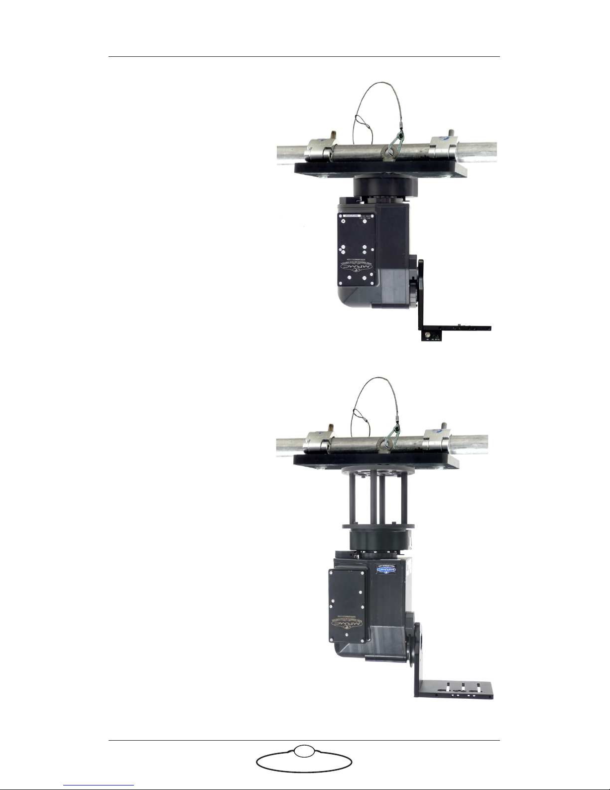
1. Mount the AFC head onto your choice of support, such as a
heavy-duty tripod or metal plate.
More information on mounting sockets and dimensions can be
found in Appendix 3 Specifications.
Example: AFC head
mounted directly onto
tripod with single
3/8-16 tripod
mounting bolt:
Example: AFC head
mounted on an
optional riser mounted
on a table, to give the
head more height and
Tilt clearance. Further
details are on page 48.
AFC Quick Start Guide
3
Example: AFC head
underslung and
directly mounted onto
scaffolding plate.
Further details are on
page 50.
For notes on zeroing
the axes when using an
underslung
configuration, see page
16.
Example: AFC head
underslung and
mounted onto riser
which is, in turn,
mounted onto a
scaffolding plate.
Further details are on
page 51.
AFC Quick Start Guide
4
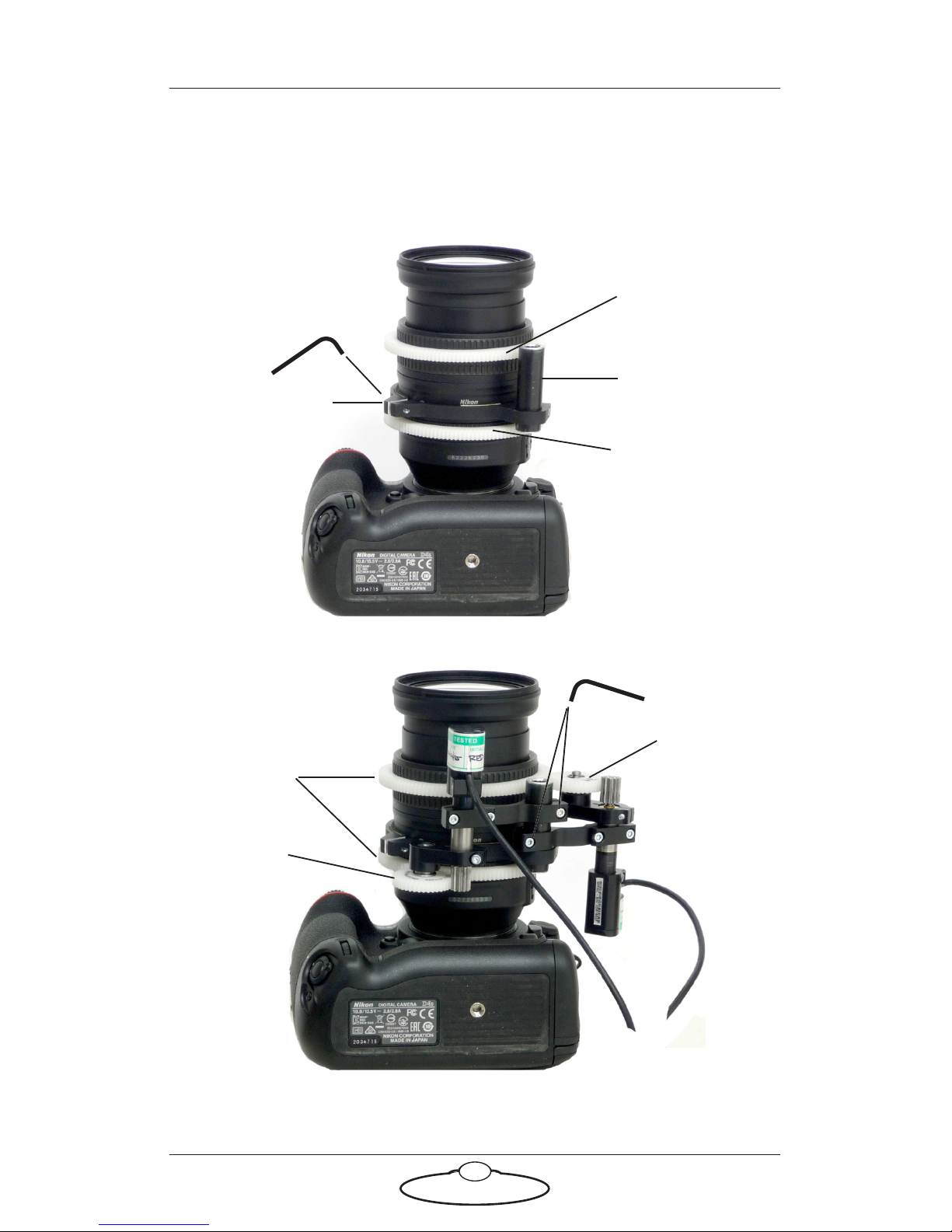
2. If you are using serial (digital) Lens Control Motors (LCMs) for
focus, zoom, and iris (aperture) then skip this step and go on to step
3 on page 7.
If you are using optional external (LCMs) then these are ordinarily
made to your lens specifications. Set these up now as follows:
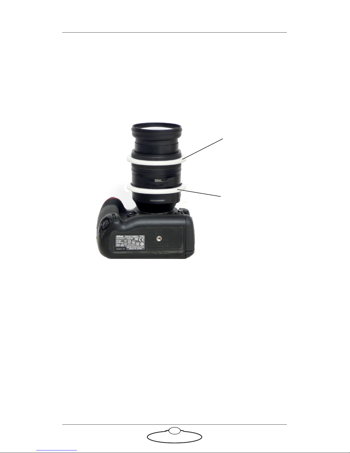
2.1 Install the large gears onto the focus, zoom, and iris rings of
your lens, as applicable.
The relative position of the rings depends on the make and
model of the lens.
Lens gear
Lens gear
(Zoom)
(Focus)
AFC Quick Start Guide
5
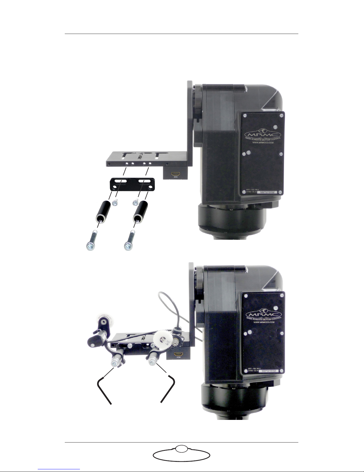
2.2 For head-mounted LCMs, bolt the mounting rods onto the
head, then mount the LCMs onto the rods in approximately
the correct position. You can fine-tune the position later:
Mounting
rods
AFC Quick Start Guide
6
2.3 For lens-mounted LCMs, attach the mounting ring onto the
lens so it does not interfere with the focus, zoom, or iris rings,
then mount the LCMs onto the rod, making sure that the LCM
gears mesh firmly with the lens gears:
Mounting ring
Mounting rod
Lens gears
LCM gear
LCM gear
Lens gear
Lens gear
(Zoom)
(Focus)
AFC Quick Start Guide
7
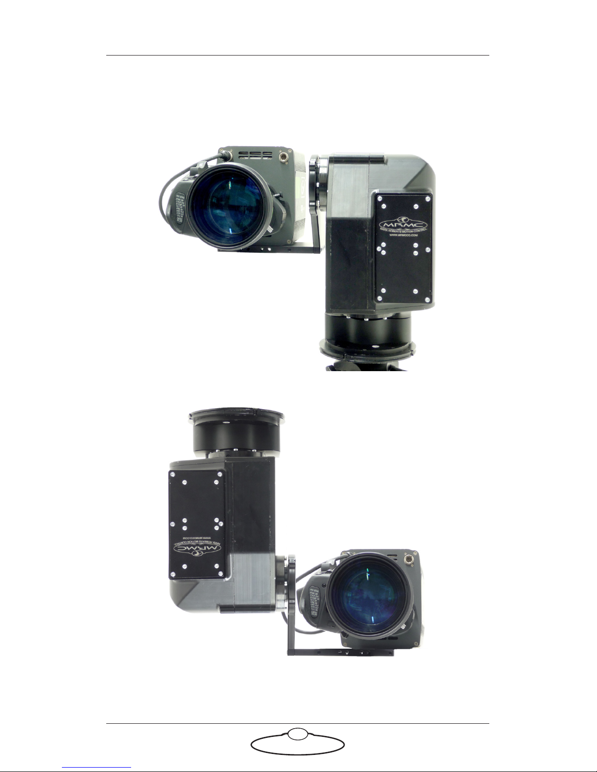
3. Place the camera on the platform, move the camera forward or
backward to balance the platform in Tilt, then insert the camera
mounting bolts under the platform and into the bottom of the
camera housing and tighten firmly.
Video camera,
overslung
Video camera,
underslung
AFC Quick Start Guide
8
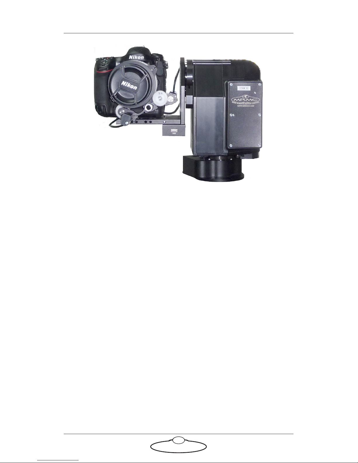
4. If you are using head-mounted LCMs, adjust their position on the
rods so that the LCM gears mesh firmly with the lens gears.
DSLR camera

AFC Quick Start Guide
9
Notes
AFC Quick Start Guide
10
Connecting the cables
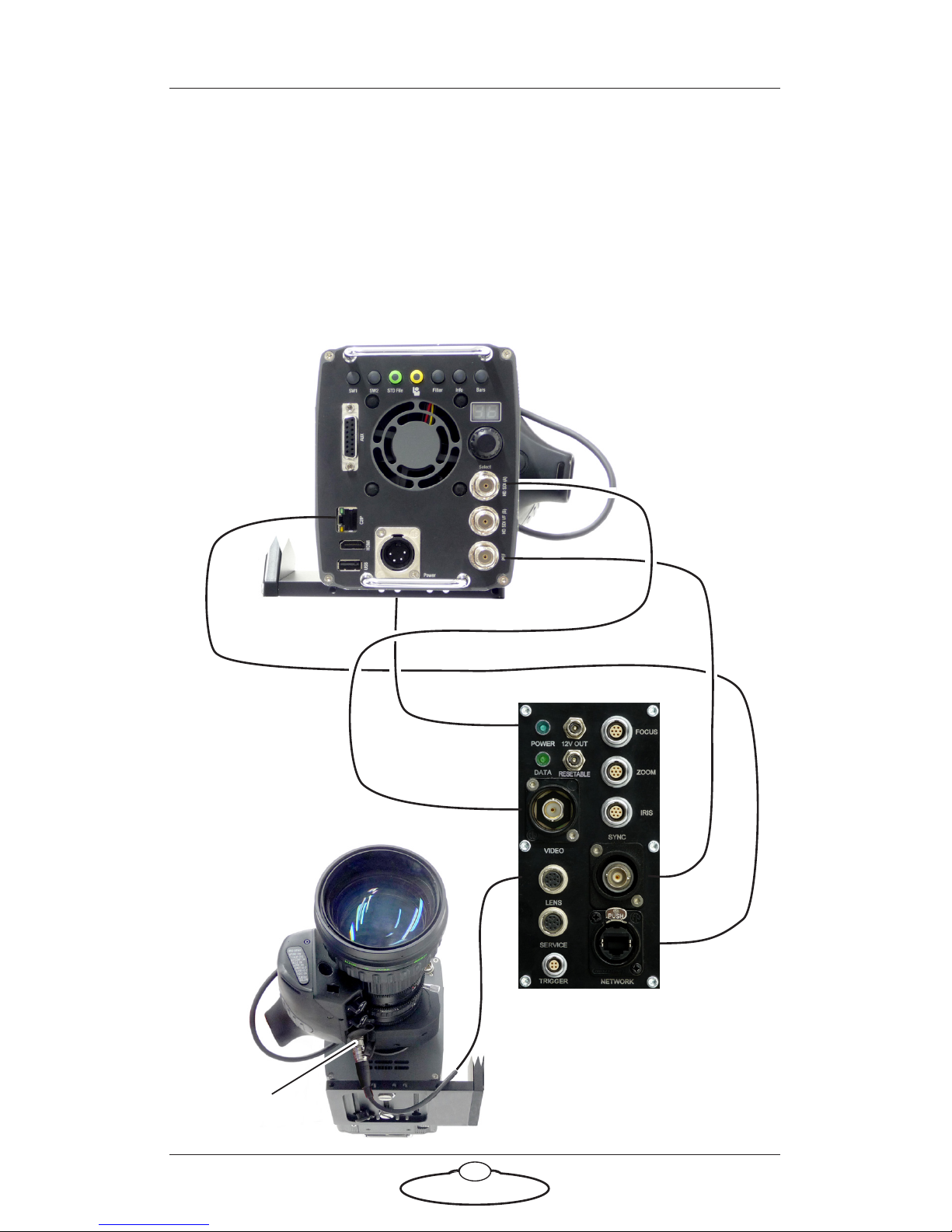
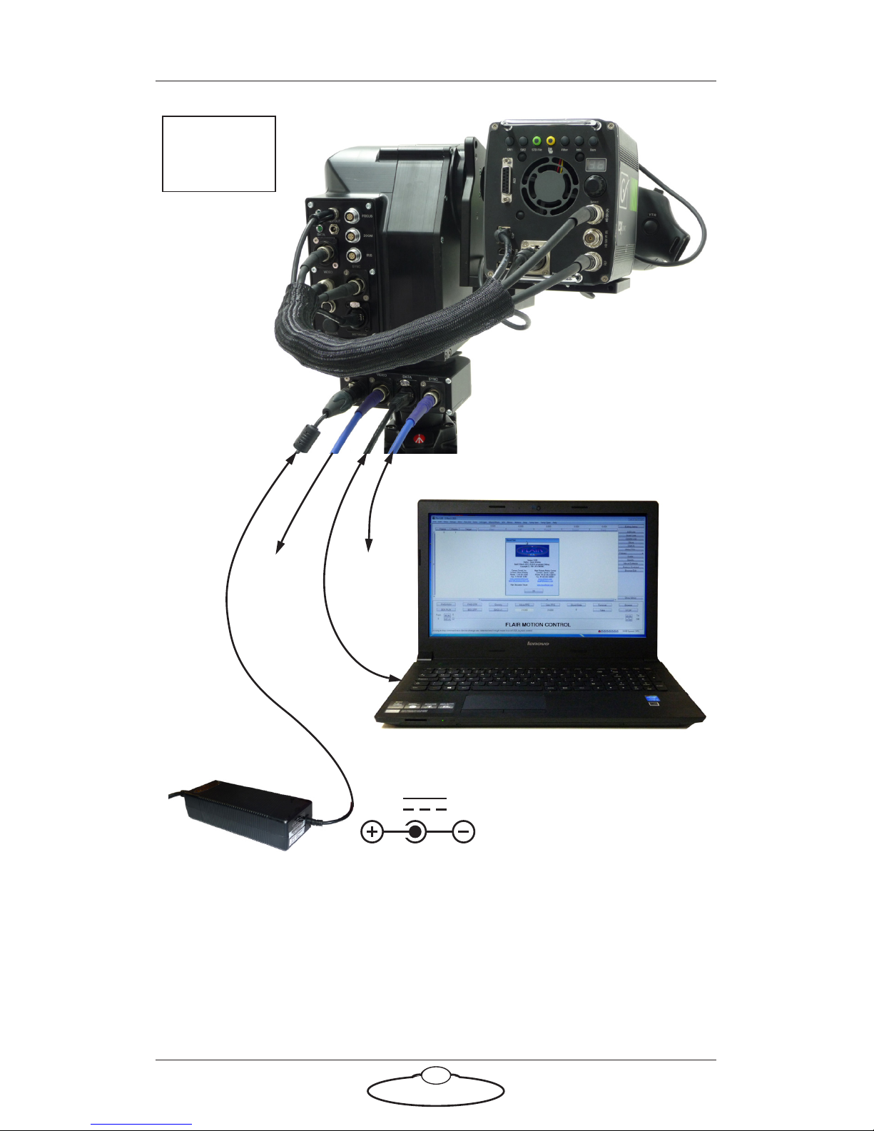
Video camera example
AFC head with BCST 043 panel, BCST 036 base, GV LDX Compact video
camera, Fujinon Digipower A22x7.8BERD-S28B Serial (digital) Lens
Control Motors, and Windows PC running Flair Motion Control
Software.
Power DC in
VIDEO
HD SDI (A)
Rear view
Front view
BCST 043 panel
Serial Lens
Control Motors
SERIAL
ETHERNET
LENS
ETHERNET
12V OUT
REF
SYNC
AFC Quick Start Guide
11
The controller can be any MRMC controller such as the Large Flat Panel
(LFP), MSA-20 Handwheels, Joystick Controller, Mini MSA, or a PC
running Flair Motion Control Software.
24V 5A
Attach the
power cables
last.
BCST 043 panel
BCST 036 base
SY
NC
PO
WER 24V
VIDEO OUT
E
THERNE
T
PC running Flair Motion
Control Software
AFC Quick Start Guide
12
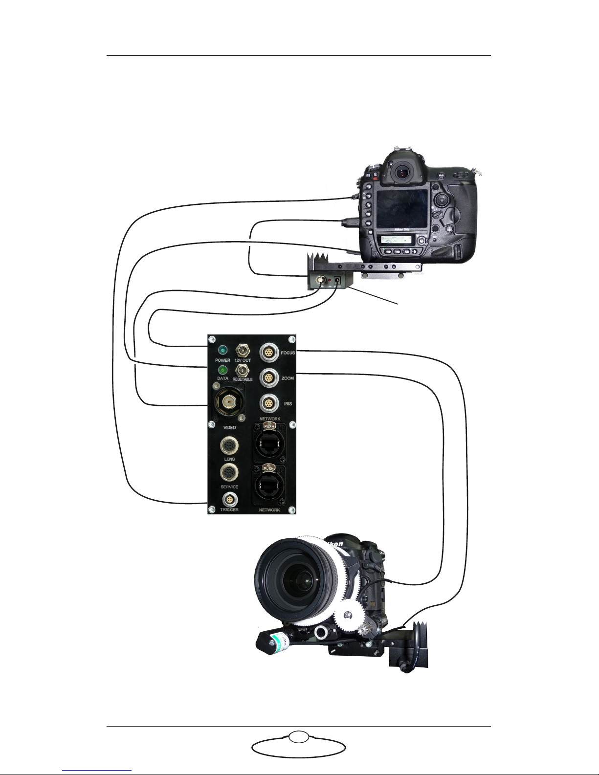
DSLR camera example
AFC head with BCST 060 panel, BCST 062 base, Nikon D4s camera,
external Lens Control Motors, and LFP controller.
TRIGGER
TRIGGER
12V OUT
RESETABLE
12V IN
HDMI
HDMI
VIDEO
SDI
12V OUT
FOCUS
ZOOM
Rear view
Front view
BCST 060 panel
External Lens
Optional
HDMI/SDI
Control Motors
5V~12V
converter
AFC Quick Start Guide
13
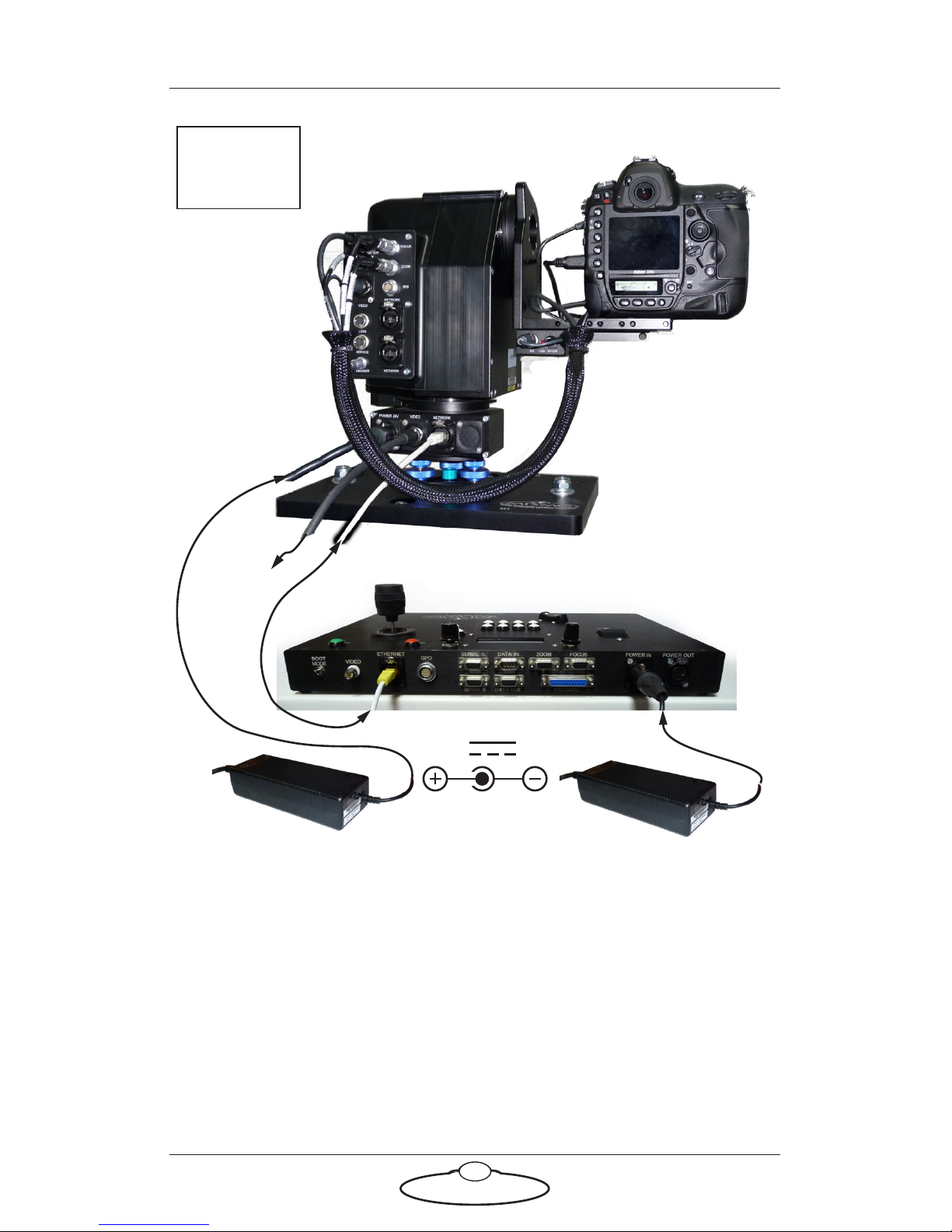
The controller can be any MRMC controller such as the Large Flat Panel
(LFP), MSA-20 Handwheels, Joystick Controller, Mini MSA, or a PC
running Flair Motion Control Software.
LFP Controller
24V 5A
POWER 24V
E
THERNE
T
VIDEO OUT
Attach the
power cables
last.
BCST 060 panel
BCST 062 base
The head and controller
both use the same type of
power supply brick.
 Loading...