

Page 1
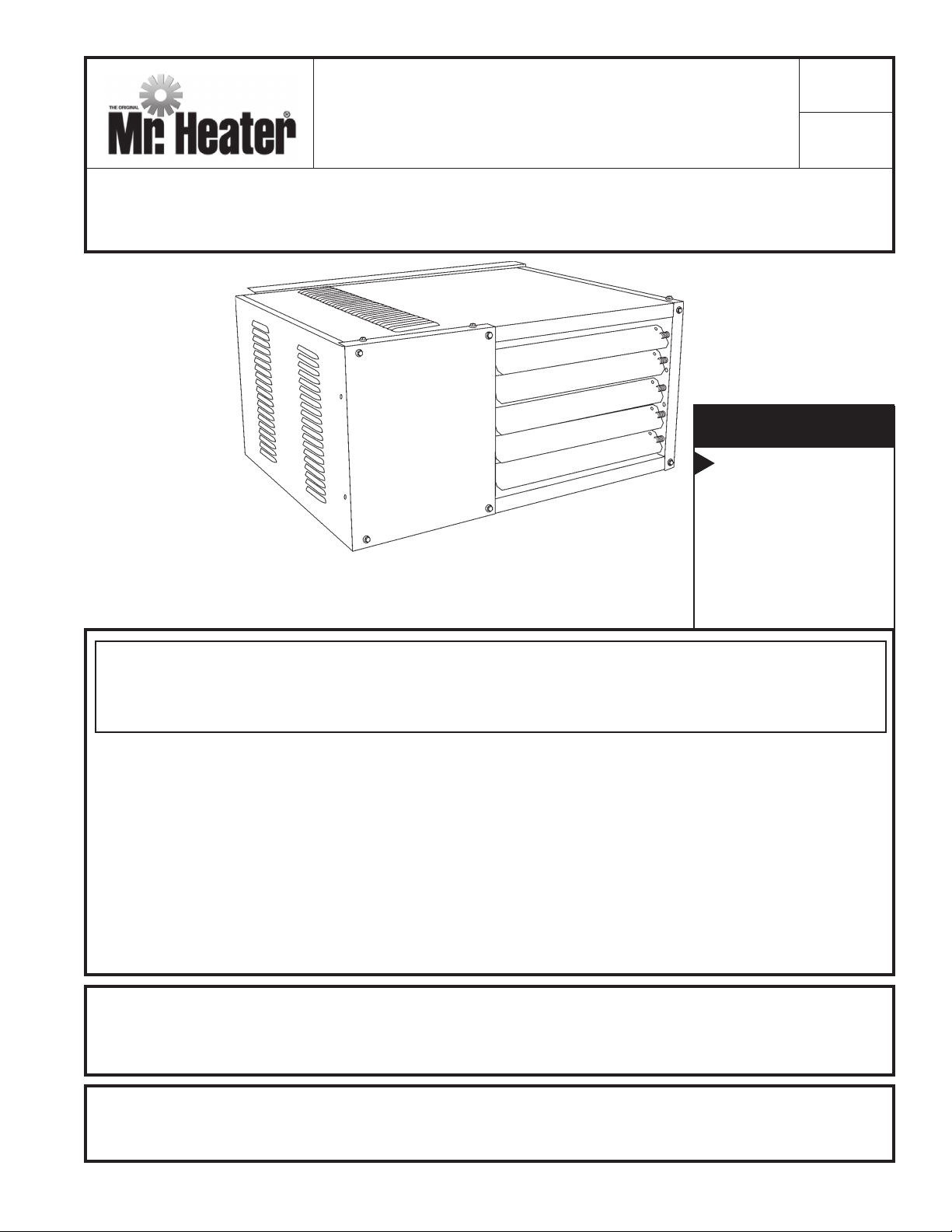
OPERATING INSTRUCTIONS
Model #
AND OWNER’S MANUAL
READ INSTRUCTIONS CAREFULLY: Read and follow all instructions. Place instructions in a safe
place for future reference. Do not allow anyone who has not read these instructions to assemble,
light, adjust or operate the heater.
For model serial numbers,
see page E16.
LANGUAGES
ENGLISH
Pages E1 — E16
SPANISH
Pages S1 — S16
COMPACT UNIT HEATER FOR COMMERCIAL USE
COMPACT UTILITY HEATER FOR RESIDENTIAL USE
FRENCH
Pages F1 — F16
MHU 50
MHU 80
WARNING: Improper installation, adjustment, alteration, service or maintenance
can cause injury or property damage. Refer to this manual. For assistance or
additional information consult a qualified installer, service agency or the gas supplier.
—
WHAT TO DO IF YOU SMELL GAS
• Open Windows
• DO NOT try to light any appliance.
• DO NOT use electrical switches.
• DO NOT use any telephone in your house. Immediately call your local gas supplier from a
neighbor’s telephone. Follow the gas supplier’s instructions.
• Do not touch any electrical switch; do not use any phone in your building.
• Installation and service must be performed by a qualified installer, service agency or the gas
supplier.
• If you cannot reach your gas supplier, call the Fire Department.
FOR YOUR SAFETY:
Do not store or use gasoline or other flammable vapors and liquids in the vicinity of this or any other appliance.
WARNING: If the information in these instructions are not followed exactly, a fire or
explosion may result causing property damage, personal injury or loss of life.
02/12 Rev. 12A #60185MR. HEATER, INC., 4560 W. 160TH ST., CLEVELAND, OHIO 44135 •800-251-0001
Page 2
WARNING:
YOUR SAFETY IS IMPORTANT TO YOU AND TO OTHERS,
SO PLEASE READ THESE INSTRUCTIONS BEFORE YOU
OPERATE THIS HEATER.
GENERAL HAZARD WARNING:
FAILURE TO COMPLY WITH THE PRECAUTIONS AND
INSTRUCTIONS PROVIDED WITH THIS HEATER, CAN
RESULT IN DEATH, SERIOUS BODILY INJURY AND
PROPERTY LOSS OR DAMAGE FROM HAZARDS OF
FIRE, EXPLOSION, BURN, ASPHYXIATION, CARBON
MONOXIDE POISONING, AND/OR ELECTRICAL SHOCK.
ONLY PERSONS WHO CAN UNDERSTAND AND FOLLOW
THE INSTRUCTIONS SHOULD USE OR SERVICE THIS
HEATER.
IF YOU NEED ASSISTANCE OR HEATER INFORMATION
SUCH AS AN INSTRUCTION MANUAL, LABELS, ETC.
CONTACT THE MANUFACTURER.
THE STATE OF CALIFORNIA REQUIRES THE FOLLOWING WARNINGS:
WARNING:
FIRE, BURN, INHALATION, AND EXPLOSION HAZARD.
KEEP SOLID COMBUSTIBLES, SUCH AS BUILDING
MATERIALS, PAPER OR CARDBOARD, A SAFE DISTANCE
AWAY FROM THE HEATER AS RECOMMENDED BY THE
INSTRUCTIONS NEVER USE THE HEATER IN SPACES
WHICH DO OR MAY CONTAIN VOLATILE OR AIRBORNE
COMBUSTIBLES, OR PRODUCTS SUCH AS GASOLINE,
SOLVENTS, PAINT THINNER, DUST PARTICLES OR
UNKNOWN CHEMICALS.
WARNING: Combustion by-products produced when using this product contain carbon monoxide, a chemical
known to the State of California to cause cancer and birth defects (or other reproductive harm).
WARNING: This product contains chemicals, including lead, known to the State of California to cause cancer and
birth defects or other reproductive harm. Wash your hands after handling.
CONTENTS
UNIT DIMENSIONS ................................................................E-4
SHIPPING ...............................................................................E-5
REQUIREMENTS .....................................................................E-5
UNIT HEATER INSTALLATION..................................................E-6
COMBUSTION & VENTILATION AIR ........................................E-6
VENTING .......................................................................... E-6-10
ELECTRICAL CONNECTIONS ................................................. E-10
GAS CONNECTION ...............................................................E-11
LEAK CHECK .........................................................................E-11
START-UP OPERATION ...........................................................E-11
HEATING SEQUENCE OF OPERATION ................................... E-12
IGNITION CONTROL LED ...................................................... E-12
ADJUSTMENTS..................................................................... E-12
SERVICE ............................................................................... E-13
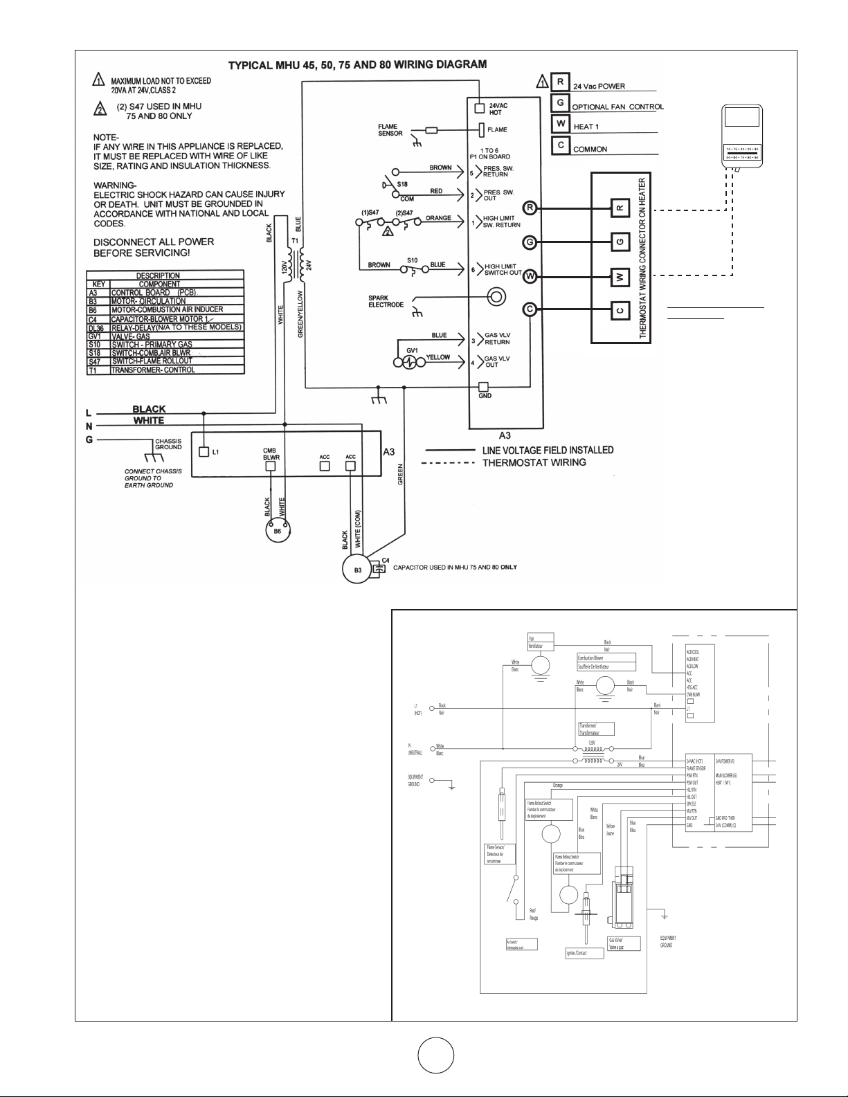
WIRING DIAGRAM ............................................................... E-13
PARTS LIST ........................................................................... E-14
WARRANTY ......................................................................... E-16
Compact Unit / Utility Heater Operating Instructions and Owner’s Manual
E-2
Page 3
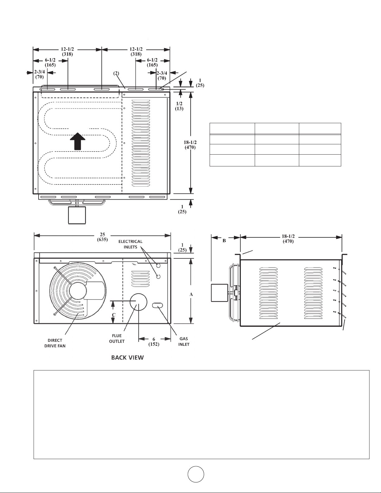
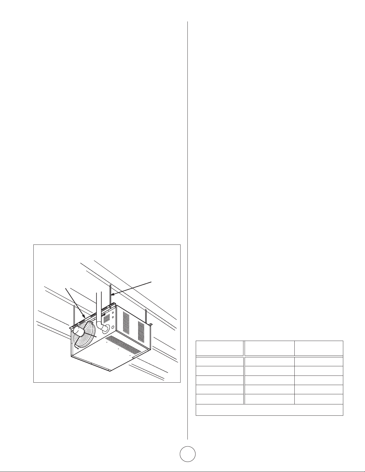
AIR
FLOW
HEAT EXCHANGER
(ALUMINIZED STEEL)
HANGING
BRACKETS
MHU 50/MHU 80 UNIT DIMENSIONS
(N-NATURAL GAS, P-PROPANE)
MOUNTING SLOTS (Typical)
5/16 x 3 Inches (8 x 76 mm)
DIMENSION 50 80
A 12 (305) 17 (432)
B 5-1/2 (140) 6-1/2 (165)
C 4-1/4 (108) 6-3/4 (171)
TOP VIEW
START–UP AND PERFORMANCE CHECK LIST
Job Name: __________________________________________
Job Location: ________________________________________
Installer: ____________________________________________
Unit Model No.: ______________________________________
Electrical Connections Tight? _______________________________________________
Supply Voltage ___________________________________________________________
Gas Piping Connections Tight & Leak-Tested? __________________________________
Motor Amps _____________________________________________________________
Furnace Btu Input ________________________________________________________
Line Pressure ____________________________________________________________
Manifold Pressure w.c. ____________________________________________________
Job No.: ______________________________________
City: _________________________________________
City: _________________________________________
Serial No.:_____________________________________
HANGING
BRACKETS (2)
ADJUSTABLE
SERVICE
ACCESS PANEL
LOUVERS
SIDE VIEW
Date: _______________________________________
State/Province: _______________________________
State/Province: _______________________________
Service Technician: ____________________________
Flue Connections Tight? __________________________________________________
Fan Timer Operation Checked? _____________________________________________
THERMOSTAT
Calibrated? _____________________________________________________________
Heat Anticipator Properly Set?
Level? _________________________________________________________________
E-3
Operating Instructions and Owner’s ManualCompact Unit / Utility Heater
Page 4
SHIPPING
The heater is completely assembled. Installation instructions,
two mounting brackets (shipped loose), and a flue transition are
included. Check the unit for shipping damage. The receiving party
should contact the last carrier immediately if any shipping damage
is found.
REQUIREMENTS – CSA IN THE USA
Installation of gas unit heaters must conform with local building
codes or, in the absence of local codes, with the current National
Fuel Gas Code ANSI Z223.1.
Installation in aircraft hangers must be in accordance with the
current Standard for Aircraft Hangers ANSI/NFPA No. 409.
Installation in parking structures must be in accordance with the
current Standard for Parking Structures ANSI/NFPA No. 88A.
Installation in repair garages must be in accordance with the
current Standard for Repair Garages ANSI/NFPA No. 88B.
These units are approved for residential applications. For
installation in a residential garage these units must be installed
so that the bottom of the heater is located no less than 8 feet
(2.438m) above floor. Heater must be located or protected to
avoid physical damage by vehicles. Refer to the National Fuel Gas
Code, ANSI Z223.1, current edition.
Authorities having jurisdiction should be consulted before NFPA
installation. Air for combustion and ventilation must conform
to the methods outlined in ANSI Z223.1, section 5.3, Air for
Combustion and Ventilation, or applicable provisions of local
building codes. The National Fuel Gas Code is available from:
American National Standard Institute Inc.
11 West 42nd Street
New York, NY 10036
These units are CSA International design certified. These unit
heaters are certified for installation to combustible material
as listed in table 1 and on unit rating plate. Accessibility and
service clearances must be observed in addition to fire protection
clearances.
All electrical wiring and ground for unit must be in accordance
with the regulations of the current National Electric Code ANSI/
No. 70.
The National Electric Code is available from:
National Fire Protection Association
1 Batterymarch Park
PO Box 9101
Quincy, MA 02269-9101
TABLE 1
UNIT CLEARANCES
Top Sides Access Panel
in mm in mm in mm
1 25 1 25 18 457
Bottom Rear Single Wall Vent*
in mm in mm in mm
0 0 18 456 6 152
*Except for listed clearance thimbles.
REQUIREMENTS – CSA IN CANADA
The instructions are intended only as a general guide and do not
supersede local codes in any way. Authorities having jurisdiction
should be consulted before installation. The installation must
conform with local building codes or in the absence of local
codes, with the current CSA B149.1, Natural Gas and Propane
Installation Code. All electrical wiring and grounding for the unit
must also comply with the Canadian Electrical Code CSA C22.1,
current edition.
These heaters are CSA International certified for the clearances to
combustible material listed on the rating plate and table1. Provide
adequate clearance around air openings into the combustion
chamber, clearances from combustible material, and provisions
for accessibility and for combustion and ventilation air supply.
Provision shall be made for service accessibility to the heater.
Note that fire protection clearances may be exceeded to provide
additional space for service and accessibility.
GARAGE INSTALLATIONS:
Installation in parking structures must be in accordance with the
current Standard for Parking Structures ANSI/NFPA No. 88A.
Installation in repair garages must be in accordance with the
current Standard for Repair Garages ANSI/NFPA No. 88B.
1. In a storage area, clearance from heaters to combustible
materials must be such that the material shall not attain a
temperature above 160°F by continuous operation of the unit.
2. Eight foot minimum clearance from the floor to the bottom
of the heater must be maintained. Refer to the CSA B149.1,
Natural Gas and Propane Installation Code
AIRCRAFT HANGER:
Installation of gas unit heaters must conform with local building
codes or, in the absence of local codes, with the current National
Fuel Gas Code ANSI Z223.1.
1. In an area where aircraft are housed or serviced, 10’
minimum clearance from highest surface of aircraft to bottom
of the heater must be maintained.
2. In other areas, 8’ minimum clearance from the floor to
bottom of heater must be maintained.
3. Heaters should be located so as to be protected from
damage from aircraft or other appliances needed for
servicing of aircraft. Refer to requirements of the enforcing
authorities.
Compact Unit / Utility Heater Operating Instructions and Owner’s Manual
E-4
Page 5
These units are certified for residential applications. For installation
in a residential garage, these units must be installed so that
burners and ignition source are located no less than 18” (457mm)
above floor. Heater must be located or protected to avoid physical
damage by vehicles. Refer to CSA B149.1, Natural Gas and Propane
Installation Code current edition.
In a confined area, the heater must be installed in accordance
with the CSA B149.1, Natural Gas and Propane Installation Code.
Be sure to check with local codes and ordinances for additional
requirements.
UNIT HEATER INSTALLATION
Unit is shipped ready for installation. Unit may be installed as
shown in figure 1 or inverted 180
as governed by clearances, vent connection, air direction, gas
supply, electrical supply and service accessibility.
1. If installing unit in an inverted position: Remove and retain
screws securing door and rotate door 180
retained screws. Rotate louvers directing airflow as desired.
2. Choose location for mounting brackets.
3. Remove and retain three screws along top edge (bottom
edge when inverted) of front of unit.
4. Align screw holes on mounting bracket with holes along
top edge (either upright or inverted) of unit. Secure one
mounting bracket to front of unit with retained screws.
Secure other mounting bracket to back of unit with screws
provided in bag assembly containing flue transition.
5. To support unit, secure mounting bracket to ceiling joist or
truss. Unit may also hang on rods as shown in figure 1.
INSTALL UNIT / UTILITY HEATER
MOUNTING
BRACKETS (2)
o
depending on desired location
o
. Secure with
FIGURE 1
SUPPORT
RODS
Gas Code, ANSI Z223.1, in the U.S.A., CSA B149.1 Natural Gas
and Propane Installation Code, or applicable provisions of local
building codes.
All gas fired appliances require air to be used for the combustion
process. In many buildings today, there is a negative indoor air
pressure caused by exhaust fans, etc. If sufficient quantities of
combustion air are not available, the heater or another appliance
will operate in an inefficient manner, resulting in incomplete
combustion which can result in the production of excessive carbon
monoxide.
CAUTION Insufficient combustion air can cause headaches,
nausea, dizziness, asphyxiation or death.
If indoor air is to be used for combustion, it must be free of the
following substances or the life of the heat exchanger will be
adversely affected: chlorine, carbon tetrachloride, cleaning solvent,
halogen refrigerants, acids, cements and glues, printing inks,
fluorides, paint removers, varnishes, or any other corrosives.
VENTING
A – GENERAL RECOMMENDATIONS AND
REQUIREMENTS
NOTE: The vent is a passageway, vertical or nearly so, used to
convey flue gases from an appliance, or its vent connector, to the
outside atmosphere. The vent connector is the pipe or duct that
connects a fuel-gas burning appliance to a vent or chimney.
Unit heaters must be vented in compliance with all local codes
or requirements of the local utility, the current standards of the
(American) National Fuel Gas Code, ANSI Z223.1 or (Canada)
CSA B149.1 Natural Gas and Propane Installation Code, and the
following instructions.
A metal stamped/extruded transition is supplied with this certified
unit. It must not be modified or altered and must be installed
on the outlet of the induced draft blower assembly prior to the
installation of the vent or vent connector. Failure to comply with
this requirement will void the certification of the unit by the
approval agencies. All joints shall be secured with at least two
corrosion resistant screws. All joints must be checked for gas
tightness after installation.
COMBUSTION AND VENTILATION AIR
Adequate facilities for supplying air for combustion and ventilation
must be provided in accordance with the latest edition of section
5.3, Air for Combustion and Ventilation, of the National Fuel
TABLE 2
MAXIMUM VENT LENGTHS
HORIZONTAL VENTS
No. of ft m
Elbows
1 25 7.6
2 20 6.1
3 15 4.6
4 10 3.0
5 5 1.5
Maximum length of vent connector not to exceed 30 ft. (9.1m).
Operating Instructions and Owner’s ManualCompact Unit / Utility Heater
E-5
Page 6
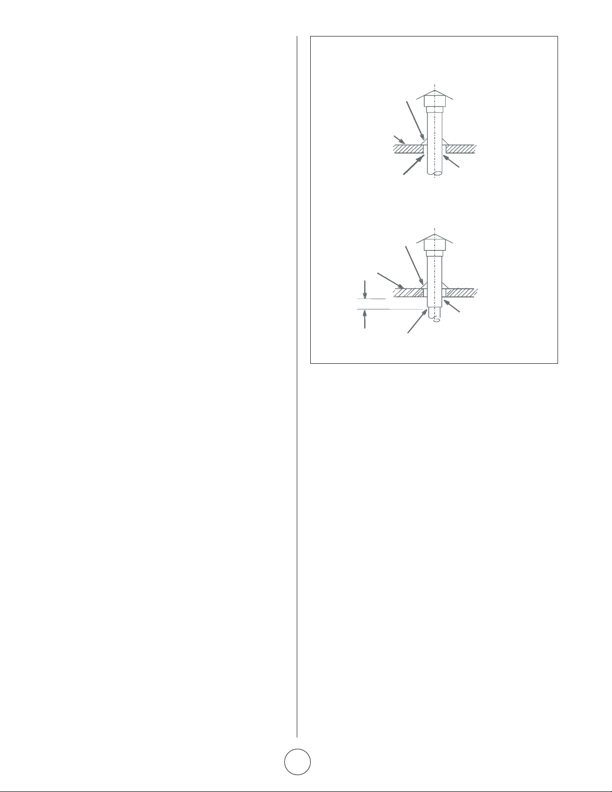
B – VERTICAL VENTS USING METAL VENT
VENT TERMINATION ON SINGLE WALL VENT
SINGLE WALL TERMINATION
DOUBLE WALL (TYPE B-1) TERMINATION
ROOF FLASHING
ROOF PITCHED
FROM 0” TO 45”
SHALL NOT BE A
CONCEALED SPACE
2” CLEARANCE
THIMBLE
ROOF FLASHING
ROOF PITCHED
FROM 0” TO 45”
12” MAX
CLEARANCE TO BE AS
SPECIFIED ON TYPE “B”
VENT PIPE
SEAL JOINT BETWEEN SINGLE WALL VENT
AND “B”VENT AND THE ANNUL AR SPACE OF THE “B” VENT
PIPE – COMMERCIAL AND RESIDENTIAL
INSTALLATIONS
HSU compact unit heaters are listed as Category I appliances for
vertical vent installations.
1. HSU unit heaters are to be used with NFPA- or ANSI-approved
chimneys, U.L. listed type B-1 gas vents, single wall metal
pipe, or listed chimney lining system for gas venting where
applicable, as well as the modifications and limitations listed
in figure 2. Seal single wall vent material according to the
section A - General Recommendations and Requirements.
2. The vent connector shall be 3” (76mm) diameter on 50 units.
In all cases, a flue transition piece (supplied) is required to
fit over the outlet of the induced draft assembly on the
appliance.
3. Keep the vent connector runs as short as possible with
a minimum number of elbows. Refer to the (American)
National Fuel Gas Code ANSI Z223.1 or (Canada) CSA B149.1
Natural Gas and Propane Installation Code for maximum
vent and vent connector lengths. Horizontal run of the vent
connector from the induced draft blower to the chimney/vent
cannot exceed the values in table 2.
4. When the length of a single wall vent, including elbows,
exceeds 5 feet (1.5m), the vent shall be insulated along
its entire length with a minimum of 1/2” thick foil faced
fiberglass 1-1/2# density insulation. If a single wall vent is
used in an unheated area it shall be insulated. Failure to do
so will result in condensation of flue gases.
5. The unit may be vented vertically as a single appliance or as
a common vent with other gas-fired appliances. In common
venting situations, vent connectors for other appliances
must maintain a 4” (100mm) vertical separation between
the vent connectors. Refer to common venting tables in the
(American) National Fuel Gas Code ANSI Z223.1 or (Canada)
CSA B149.1 Natural Gas and Propane Installation Code for
proper vent size.
6. Clearance to combustible material is 6” (152mm) for single
wall vent material except where a listed clearance thimble is
used. Clearance to combustible material for type B-1 vent or
factory-built chimney is per manufacturer’s instructions.
7. The vent connector shall be supported without any dips or
sags. Vertical vents shall be supported in accordance with
their listing and manufacturers’ instructions. All horizontal
vent connector runs shall have a slope up to the vertical vent
of at least 1/4” per foot (1mm per 50mm).
8. All vertical type B-1 vents, single wall vents, or listed chimney
lining system must be terminated with a listed vent cap or
listed roof assembly.
9. The vent must extend at least 3’ (1m) above the highest point
where it passes through a roof of a building and at least 2’
(0.6m) higher than any part of a building within a horizontal
distance of 10’ (3.05m) unless otherwise specified by the
(American) National Fuel Gas Code, ANSI Z223.1 or (Canada)
CAN/CGA-B149 Installation Code. The vent must extend at
least 5’ (1.6m) above the highest connected equipment flue
collar.
Compact Unit / Utility Heater Operating Instructions and Owner’s Manual
FIGURE 2
C – HORIZONTAL VENTING – GENERAL
Due to changes to Z83-8 2009 CSA2.6-2009, the use of single
wall B-Vent is no longer permitted as an acceptable material
when venting horizontally, this change covers both residential
and commercial installations. All horizontally vented units
manufactured after July of 2011 must be vented as a Caterory
III Unit/Utility Heater in compliance with UL 1738 & ULS636.
Common venting is not allowed when horizontally venting the unit
heater.
The minimum horizontal vent length is three feet (914mm).
1. If possible, do not terminate the horizontal vent through a
wall that is exposed to prevailing wind. Exposure to excessive
winds can affect unit performance.
2. Vent termination must be free from obstructions and at least
12” (306mm) above grade level and maximum snow height.
3. Do not terminate vent directly below roof eaves or above
a walkway, or any other area where condensate dripping
may be troublesome and may cause some staining. Avoid
windows where steam may cause fogging or ice buildup.
4. When horizontally vented, minimum clearance for termination
from any door, window, gravity air inlet, gas or electric
meter, regulators, and relief equipment is 4 ft. (1.2m) for U.S.
installations. Refer to NFPA 54/ANSI Z223.1 in the U.S.A. and
CSA B149.1 Natural Gas and Propane Installation Code and
.2 in Canada or with authorities having local jurisdiction. In
Canada, vent termination must have a minimum 6 ft. (1.8
m) horizontal clearance from gas and electric meters and
relief devices as specified in the Canadian B149.1, Natural Gas
Installation Code.
E-6
Page 7
5. Vent termination must be a minimum of 4’ (1.2m) below or
4’ (1.2m) horizontally from any soffit vent or under-eave vent.
6. Vent must be a minimum of 6’ from an inside corner formed
by two exterior walls. If possible, leave a 10’ clearance.
7. Vent termination must be a minimum of 10’ (3m) from any
forced air inlet (includes fresh air inlet for other appliances,
such as a dryer).
8. When termination is routed through an exterior combustible
wall the vent must be supported using a listed clearance
thimble. Seal the connection between the single wall and
double wall pipes and the annular space of the double wall
pipe as shown in figure 2. Inside edge of vent termination
tee must be at least 12 inches from outside wall as shown in
figure 3.
9. For horizontal venting, the vent pipe shall be supported with
hangers no more than 3ft. (1m) apart to prevent movement
after installation.
D – HORIZONTAL VENTING – COMMERCIAL
1. Horizontal commercial installations are for buildings which
are not attached to living spaces. The vent may be single wall
vent material installed according to the sections
Venting A - General Recommendations and
Requirements and C - Horizontal Venting General and D -
Horizontal Venting - Commercial. Refer to figure 3.
2. The vent pipe diameter for horizontal commercial installations
shall be 4” (76mm) on 50 units. In all cases, a flue transition
piece (supplied) is required to fit over the outlet of the
induced draft assembly on the appliance.
3. Refer to table 2 for maximum vent connector lengths.
4. Select a wall termination point that will maintain ¼” rise per
foot slope of horizontal run of vent pipe.
5. For upward sloped vent a condensate tee and drain must
be installed within the first 5’ (1.5m) from the unit heater
to protect the appliance. If a flexible condensate drain line
is used, the drain line must include a loop entering the
structure. If the unit is shut down for an extended period of
time and will be exposed to sub-freezing temperatures, the
condensate may freeze.
E – HORIZONTAL VENTING – RESIDENTIAL
1. For horizontal residential installations these units are
certified as Category III appliances. Venting A - General
Recommendations and Requirements and C - Horizontal
Venting General and E - Horizontal Venting - Residential.
Refer to figure 6.
2. The vent pipe diameter for horizontal residential installations
shall be 4” (100mm) on 50 and 80 units. A standard vent
transition is required at unit in addition to the transition
supplied with the unit.
3. The maximum vent length is 5’ (1.5m) plus one 90-degree
elbow. The minimum length is 3’(.91m).
4. The vent must maintain a ¼” rise per foot of slope upwards
toward the termination.
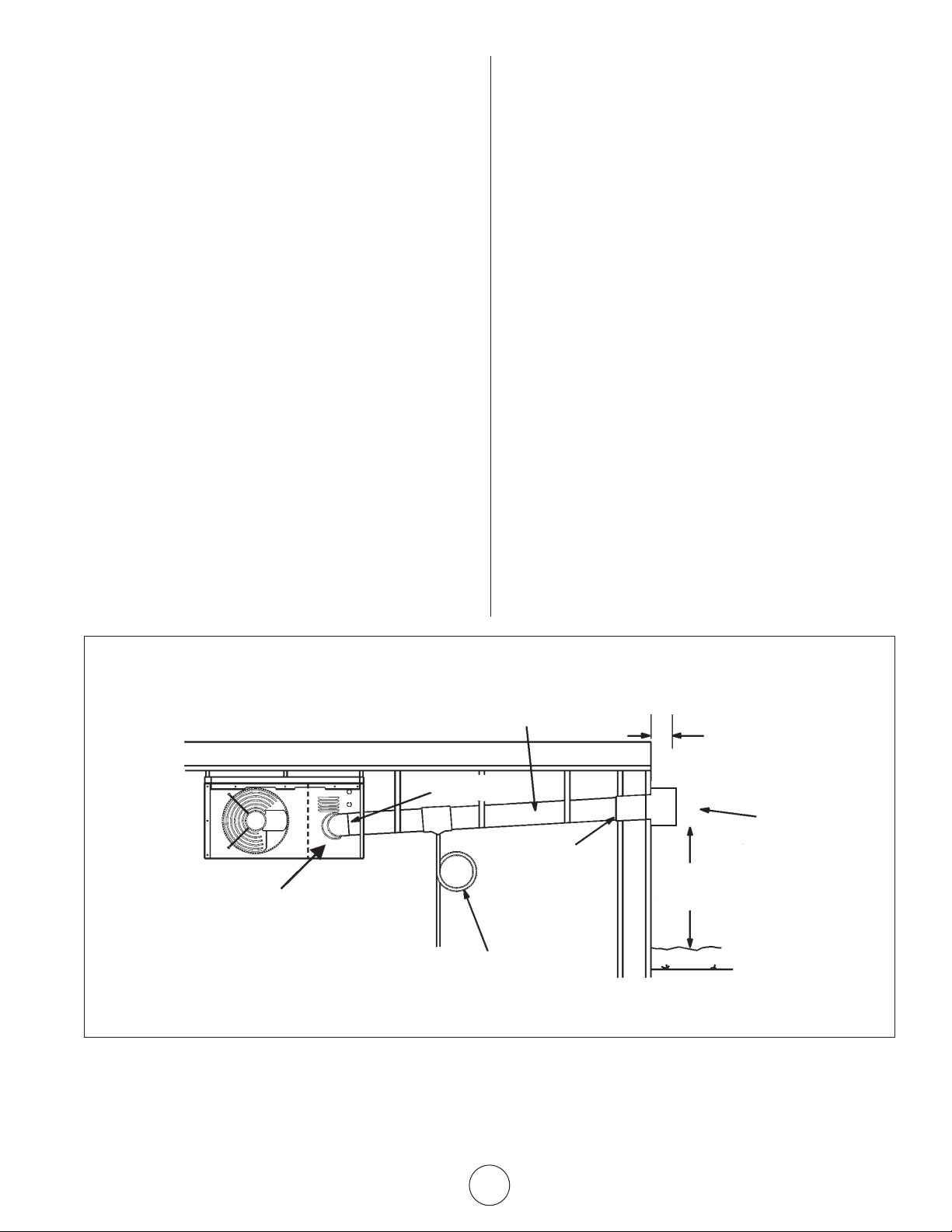
CONDENSATE DRAIN THROUGH TEE PIPE AND DRAIN LOOP
UPWARD SLOPE ON HORIZONTAL VENT-COMMERCIAL INSTALLATION
CATEGORY III VENT ACCORDING TO THESE INSTALLATION INSTRUCTIONS.
SLOPE: + 1/4 INCH FOR 1 FOOT RUN MINIMUM.
INDUCED DRAFT BLOWER
NOTE - MINIMUM HORIZONTAL LENGTH 3 FT. (914MM),
NOT INCLUDING CAP FOR TERMINATION. REFER TO TABLE
2 FOR MAXIMUM LENGTH AND NUMBER OF ELBOWS.
COMMON VENTING NOT ALLOWED WHEN HORIZONTALLY VENTING THE UNIT / UTILITY HEATER
FLUE TRANSITION
(PROVIDED)
LISTED THIMBLE
THROUGH COMBUSTIBLE
WALL
DRAIN LOOP WITH WATER
TRAP (TO CONDENSATE DRAIN)
FIGURE 3
12 INCHES MIN.
(30.5 CM)
EXHAUST VENT
TERMINATION TEE
12” (30.5 CM)
MINIMUM ABOVE ALL
HIGHEST SNOWFALL
E-7
Operating Instructions and Owner’s ManualCompact Unit / Utility Heater
Page 8
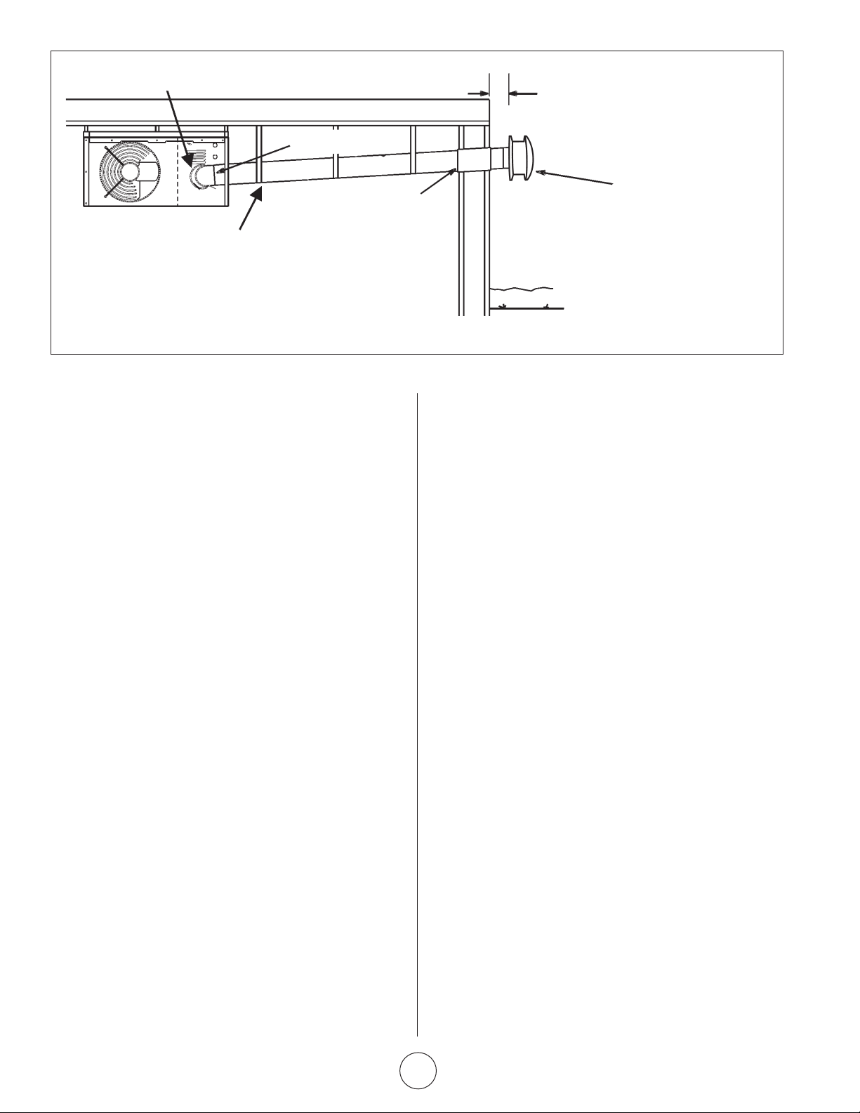
INDUCED DRAFT BLOWER
CATEGORY III VENT ACCORDING TO THESE INSTALLATION
INSTRUCTIONS.
SLOPED: + 1/4 INCH FOR 1 FOOT RUN MINIMUM.
NOTE - MINIMUM HORIZONTAL LENGTH 3FT. (914MM), NOT
INCLUDING CAP FOR TERMINATION.
MAXIMUM HORIZONTAL LENGTH 5FT. (1.5M) PLUS ONE
90-DEGREE ELBOW.
COMMON VENTING NOT ALLOWED WHEN HORIZONTALLY VENTING THE UNIT / UTILITY HEATER.
HORIZONTAL VENTING - RESIDENTIAL INSTALLATION
FLUE TRANSITION
(PROVIDED)
UPWARD SLOPE
12 INCHES
MIN. (30.5CM)
VENT TERMINATION CAP
LISTED THIMBLE THROUGH
COMBUSTION WALL
FIGURE 6
F – VENTING USING A MASONRY CHIMNEY
The following additional requirements apply when a lined masonry
chimney is being used to vent the compact unit / utility heater.
1. Masonry chimneys used to vent Category I units heaters
must be either tile-lined or lined with a listed metal lining
system or dedicated gas vent. Unlined masonry chimneys are
prohibited. A category I appliance must never be connected
to a chimney that is servicing a solid fuel appliance. If a
fireplace chimney flue is used to vent this appliance, the
fireplace opening must be permanently sealed.
2. A fan assisted unit heater may be commonly vented into an
existing lined masonry chimney provided:
• The chimney is currently serving at least one draft-hood
equipped appliance.
• The vent connector and chimney are sized in accordance
with venting tables in the (American) National Fuel Gas
Code ANSI Z223.1 or (Canada) CSA B149.1 Natural Gas
and Propane Installation Code.
IMPORTANT Single appliance venting of a fan assisted unit
heater into a tile lined masonry chimney (interior or outside wall)
is prohibited. The chimney must first be lined with either type B-1
vent or an insulated single wall flexible vent lining system, sized
in accordance with venting tables in the (American) National Fuel
Gas Code ANSI Z223.1 or (Canada) CSA B149.1 Natural Gas and
Propane Installation Code.
3. A type B-1 vent or masonry chimney liner shall terminate
above the roof surface with a listed cap or a listed roof
assembly in accordance with the terms of their respective
listings and the vent manufacturer’s instructions.
4. Do not install a manual damper, barometric draft regulator, or
flue restrictor between the unit heater and the chimney.
5. If type B-1 double-wall vent is used inside a chimney, no other
appliance can be vented into the chimney. Outer wall of type
B-1 vent pipe must not be exposed to flue products.
6. Insulation for the flexible vent pipe must be an encapsulated
fiberglass sleeve recommended by the flexible vent pipe
manufacturer.
7. The space between liner and chimney wall should NOT
be insulated with puffed mica or any other loose granular
insulating material.
8. If type B-1 vent or an insulated flexible vent pipe cannot be
used as liners, the chimney must be rebuilt to accommodate
one of these methods or some alternate approved method
must be found to vent the appliance. When inspection
reveals that an existing chimney is not safe for the intended
purpose, it shall be rebuilt to conform to nationally
recognized standards, lined or relined with suitable materials
or replaced with a gas vent or chimney suitable for venting
unit heaters. The chimney passageway must be checked
periodically to ensure that it is clear and free of obstructions.
G – REMOVAL OF UNIT FROM COMMON VENT
In the event that an existing unit heater is removed from a venting
system commonly run with separate gas appliances, the venting
system is likely to be too large to properly vent the remaining
attached appliances. The following test should be conducted while
each appliance is in operation and the other appliances are not in
operation, yet remain connected to the common venting system.
If the venting system has been installed improperly, the system
must be corrected.
1. Seal any unused openings in the common venting system.
2. Visually inspect the venting system for proper size and
horizontal pitch. Determine there is no blockage or
restriction, leakage, corrosion, or other deficiencies which
could cause an unsafe condition.
3. If practical close all building doors and windows and all
doors between the space in which the appliances remaining
connected to the common venting system are located and
other spaces of the building. Turn on clothes dryers and any
appliances not connected to the common venting system.
Turn on any exhaust fans, such as range hoods and bathroom
exhausts, so they will operate at maximum speed. Do not
operate a summer exhaust fan. Close fireplace dampers.
4. Follow the lighting instructions. Place the appliance being
inspected in operation. Adjust thermostat so appliance will
operate continuously.
Compact Unit / Utility Heater Operating Instructions and Owner’s Manual
E-8
Page 9
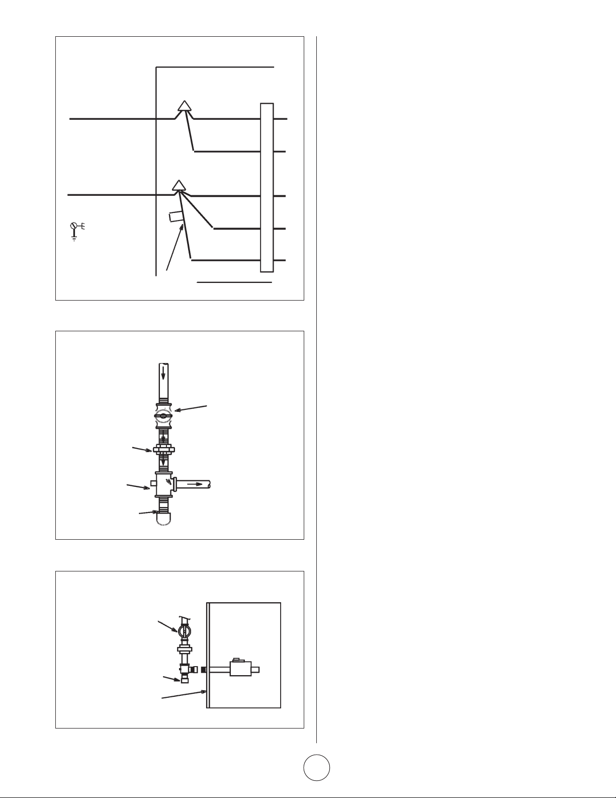
LINE VOLTAGE FIELD WIRING
L1
N
EQUIPMENT
GROUND
BLACK WIRE WITH WHITE TAPE OR
WHITE WIRE WITHOUT TAPE
FIGURE 7
GAS SUPPLY CONNECTION
GROUNDED
JOINT UNION
DRIP LEG
FIGURE 8
GAS SUPPLY TO UNIT HEATER
MANUAL MAIN SHUT-OFF VALVE
WILL NOT HOLD NORMAL TEST
PRESSURE
UNIT
BLACK
BLACK
WHITE
WHITE
MANUAL
MAIN SHUT-OFF VALVE
(FURNISHED BY INSTALLER)
GAS FLOW
ISOLATE
GAS VALVE
5. Test for spillage at the draft hood relief opening after five
minutes of main burner operation. Use the flame of a match
or candle, or smoke from a cigarette, cigar, or pipe.
6. After it has been determined that each appliance remaining
connected to the common venting system properly vents
when tested as outlined above, return doors, windows,
exhaust fans, fireplace dampers and any other gas-burning
appliance to their previous condition of use.
7. If improper venting is observed during any of the above
tests, the common venting system must be corrected. The
common venting system should be resized to approach the
minimum size as determined by using the appropriate tables
in Appendix G in the current standards of the National Fuel
Gas Code, ANSI Z223-1 in the U.S.A. and the appropriate
Category I Natural Gas and Propane appliances venting sizing
tables in the current standards of the CSA B149.1 Natural Gas
and Propane Installation Code in Canada.
NOTE Local codes may supersede any of the above provisions.
ELECTRICAL CONNECTIONS
NOTE The MHU series unit heaters use a direct spark ignition
NOTE: The MHU/HSU series unit/utility heaters use a direct spark
system. There is no pilot necessary as the spark lights the
ignition system. There is no pilot necessary as the spark lights
main burner as the gas valve is turned on. The direct spark
the main burner as the gas valve is turned on. The direct spark
ignition control board emits radio noise during burner ignition.
The level of energy may be enough to disturb a logic circuit in a
microprocessor controlled thermostat. It is recommended that
an isolation relay be used when connecting the unit heater to a
microprocessor controlled thermostat. Select circuit protection
and wire size according to the unit rating plate. Install a separate
disconnect switch (protected by either fuse or circuit breaker) near
the unit so that power can be turned off for servicing. Remove
electrical junction box cover and connect wiring through knockout
on the junction box located on the side of the heater. Refer to
heater wiring diagram for connection information. Use 18 gauge
wire or larger for line power connections. Make sure to connect
line power to wires located in the external electrical junction box
behind junction box cover. DO NOT CONNECT LINE POWER TO
THERMOSTAT TERMINAL STRIP ON OUTSIDE OF HEATER.
Electrically ground the unit in accordance with local codes or
in the absence of local codes, in accordance with the current
National Electrical Code (ANSI/NFPA No. 70) in the USA, and in
Canada with the current Canadian Electrical Code, Part 1 CSA
C22.1
NOTE: Un-insulated ground wire must be warped in electrical tape
to avoid damage to the electrical system.
Make line voltage connections as shown in figure 7. Connect field
wiring as shown on wiring diagram on unit. Also, refer to typical
diagram in this manual.
An additional thermostat wire must be run to terminal g on
heater when continuous blower is desired. Thermostat (optional).
See wiring schematic on pager E-13.
CAP
UNIT HEATER
FIGURE 9
E-9
Operating Instructions and Owner’s ManualCompact Unit / Utility Heater
Page 10
ignition control board emits radio noise as the sparking process
WARNING
is underway. The level of energy may be sufficient to disturb
a logic circuit in a microprocessor controlled thermostat. It is
recommended that an isolation relay be used when connecting
the unit heaters to a microprocessor controlled thermostat.
Install the thermostat according to instructions provided. Select
circuit protection and wire size according to the unit rating plate.
Install a separate disconnect switch (protected by either fuse or
WARNING
circuit breaker) near the unit so that power can be turned off
for servicing. Connect wiring through knockout on the junction
box located on the side of the unit heater. Refer to heater wiring
diagram for connection information. Use 18 gauge wire or larger
for thermostat connections.
Electrically ground unit in accordance with local codes or, in the
WARNING
absence of local codes, in accordance with the current National
Electrical Code (ANSI/NFPA No. 70) in the U.S.A., and in Canada
with the current Canadian Electrical Code, Part 1 CSA C22.1.
NOTE Un-insulated ground wires must be wrapped in electrical
tape to avoid damage to the electrical system.
WARNING
Make line voltage connections as shown in figure 7. Connect field
wiring as shown on wiring diagram on unit. Also refer to typical
diagram in this manual. An additional thermostat wire must be
run to terminal “G” on heater when continuous blower is desired.
Electric shock hazard. Can cause injury or
death. Do not use this heater if any part has
been under water. Immediately call a qualified
service technician to inspect the furnace and
to replace any part of the control system and
any gas control which has been under water.
Danger of explosion. Can cause injury or
product or property damage. If over-heating
occurs or if gas supply fails to shut off, shut
off the manual gas valve to the appliance
before shutting off electrical supply.
Electric shock hazard. Can cause injury or
death. Before attempting to perform any
service or maintenance, turn the electrical
power to unit OFF at disconnect switch(es).
Unit may have multiple power supplies.
Danger of explosion and fire. Can cause
injury or product or property damage. You
must follow these instructions exactly.
GAS CONNECTION
GAS CONNECTION
When connecting gas supply lines, the length of the piping run
from the meter to must be considered in determining the pipe size
When connecting gas supply, the length of the run from the
to avoid excessive pressure drop. A line pressure of 7” WC (178mm
meter must be considered in determining the pipe size to avoid
WC) for natural gas should be maintained when sizing the piping.
excessive pressure drop. A line pressure of 7” w.c. (178mm w.c.)
A line pressure of 13” WC (330mm WC) should be maintained
for natural gas should be maintained when sizing piping. A line
for propane (LP) gas. For correct sizing of piping, refer to the
pressure of 13” w.c. (330mm w.c.) should be maintained for
(American) National Fuel Gas Code ANSI Z223.1, or (Canada) CSA
liquefied petroleum (LP) gas. For correct sizing of piping, refer to
B149.1, National Gas and Propane Installation Code or consult the
the (American) National Fuel Gas Code ANSI Z223.1 or (Canada)
utility having jurisdiction.
CSA B149.1, Natural Gas and Propane Installation Code or consult
WARNING: TO PREVENT HEATER DAMAGE.
the utility having jurisdiction.
WHEN USING A PROPANE TANK TO SUPPLY
A drip leg should be installed in the vertical pipe run to the unit.
HEATER, A MINIMUM 11”W.C. LOW PRESSURE
In some localities, codes may require that a manual main shutoff
REGULATOR TO A MAXIMUM 14”W.C. LOW PRESSURE
valve and union (furnished by installer) be installed external to the
REGULATOR IS REQUIRED. THIS REGULATOR MUST BE
unit. Union must be of the ground joint type. A drip leg should be
INSTALLED BETWEEN THE TANK AND THE HEATER.
readily accessible to permit cleaning and emptying. See figure 8.
Regulator not supplied with heater.
NOTE If a switch box is mounted over electrical knockouts on
A drip leg should be installed in the vertical pipe run to the unit.
back of unit, leave a minimum of 4” (102mm) clearance between
In some localities, codes may require that a manual main shutoff
switch box and drip leg.
valve and union (furnished by installer) be installed external to the
unit. Union must be of the ground joint type. A drip leg should be
A 1/8” NPT plugged tap shall be installed immediately upstream
readily accessible to permit cleaning and empting. See figure 8.
of the gas supply connection to the heater.
NOTE If a switch box is mounted over electrical knockouts on back
NOTE Compounds used on threaded joints of gas piping must be
of unit, leave a minimum of 4” (102mm) clearance between switch
resistant to the actions of liquefied petroleum gases.
box and drip leg.
A 1/8” NPT plugged tap shall be installed immediately upstream of
the gas supply connection to the heater.
NOTE Compounds used on threaded joints or gas piping must be
resistant to the actions of Liquefied petroleum gasses.
LEAK CHECK
After gas piping is completed, carefully check all piping
connections, (field and factory), for gas leaks. Use a soap solution
or other preferred means.
Due to the natural heating cycles and vibration of this unit it is
recommended, as part of its annual maintenance, to check these
connections for proper tightness and leak-check with a soap
solution or other preferred means prior to putting into service.
CAUTION DO NOT use matches, candles, flame or other sources
of ignition to check for gas leaks.
IMPORTANT The heater and its individual shut off valve must
be disconnected from the gas supply piping system during any
pressure testing of that system at test pressures in excess of 1/2
psig (3.45kPa).
The appliance must be isolated from the gas supply piping system
by closing its individual manual gas shutoff valve during any
pressure testing of the gas supply system at test pressures equal
to or less than 1/2 psig (3.45kPa). See figure 9.
NOTE In case emergency shutdown is required, shut down main
gas valve and disconnect main power to unit. These devices
should be properly labeled by the installer.
START – UP AND OPERATION
UNIT START–UP
FOR YOUR SAFETY READ BEFORE LIGHTING
BEFORE LIGHTING smell all around the appliance area for gas.
Be sure to smell next to the floor because some gas is heavier
than air and will settle on the floor.
Use only your hand to move the gas control switch to the on
position. Never use tools. Do not use excessive force to switch
valve from off to on position. Force or attempted repair may result
in a fire or explosion.
MHU 50/80 unit heaters are equipped with an automatic spark
ignition system. There is no pilot. In case of a safety shutdown,
move thermostat switch to OFF, then return the thermostat switch
to HEAT position.
Should overheating occur, or the gas supply fail to shut off, shut
off the manual gas valve to the appliance before shutting off the
electrical supply.
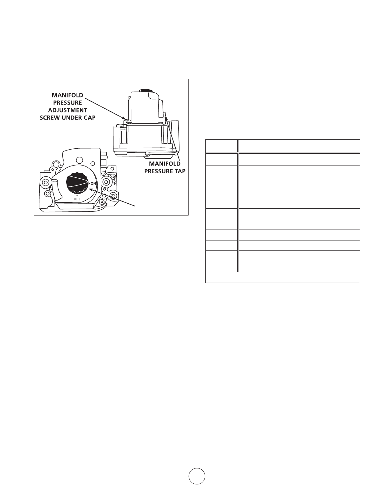
GAS VALVE OPERATION FOR HONEYWELL
VR8205M SERIES VALVE (FIGURE 10)
1. STOP! Read the safety information at the beginning of this
section.
2. Set the thermostat to lowest setting.
3. Turn off all electrical power to appliance.
4. This appliance is equipped with an ignition device which
automatically lights burner. DO NOT attempt to light the
burners manually.
5. There is a black rotary switch knob that can be moved
between the on and off position. Rotate the switch knob to
the off position. (See Figure 10)
6. Wait five minutes to clear out any gas. If you then smell gas,
STOP! Immediately call your gas supplier from a neighbor’s
phone. Follow the gas supplier’s instructions. If you do not
smell gas go to next step.
7. Rotate the black switch knob to ON.
8. Turn on electrical power to unit.
9. Set the thermostat to desired setting.
10. The combustion air blower will start. The burners will light
within 40 seconds.
Compact Unit / Utility Heater Operating Instructions and Owner’s Manual
E-10
Page 11
11. If unit does not light first time (gas line not fully purged) it
will attempt up to two more ignitions before locking out.
12. If lockout occurs, repeat steps 1 through 9.
13. If appliance still will not operate, follow the instructions “TO
TURN OFF GAS TO UNIT” and call your service technician or
gas supplier.
HONEYWELL VR8205M GAS VALVE
GAS VALVE KNOB SHOWN
IN OFF POSITION
MANIFOLD
PRESSURE TAP
flashback or burning within the burner. The flames shall
be predominantly blue in color and shall be approximately
centered in the tubes with no apparent impingement taking
place.
7. The ignition control will energize the fan approximately 45
seconds after ignition is established.
8. After the thermostat demand is satisfied the gas valve
is closed; 5 seconds after the demand is satisfied the
combustion air blower is shut off.
9. The control center shall shut off the system fan approximately
150 seconds after the gas valve is de-energized.
IGNITION CONTROL LED
The ignition control board contains a green LED which indicates
the following:
LED UNIT OPERATION
Slow Flash* Normal Operation - No call for heat
Fast Flash Normal Operation - Call for heat
Current signal at FLAME terminal 0.6 to 1.0 microamps
INLET PRESSURE TAP
MANIFOLD PRESSURE ADJUSTMENT
SCREW UNDER CAP
GAS VALVE
ROTARY SWITCH
FIGURE 10
TO TURN OFF GAS TO UNIT
1. Set thermostat to lowest level.
2. Turn off all electrical power to unit if service is to be
performed.
3. Rotate black knob
to OFF position.
HEATING SEQUENCE OF OPERATION
1. When the thermostat calls for heat, the combustion air
blower starts immediately.
2. Combustion air pressure switch proves blower operation
before allowing power to the ignition controller. This switch is
factory set and no adjustment is necessary.
3. After pre-purge of approximately 30 seconds, the spark
ignition is energized and the solenoid valves open in the gas
valve.
4. The spark then ignites the gas, the ignition sensor proves the
flame and the combustion process continues.
5. In the event that the flame is not detected after the first
10-second trial for ignition, the controller will repeat steps
3 and 4 an additional two times before locking out the gas
valve. Ignition control will then automatically repeat steps 3,
4, and 5 after 60 minutes.
To interrupt the 60-minute lockout period, move thermostat
from “Heat” to “OFF” then back to “HEAT.” Heating sequence
then restarts at step 1.
6. The burners shall light without noticeable crossover delay.
There shall be no flame lifting from the burner heads,
2 Flashes System lockout - failed to detect or sustain flame
Current signal at FLAME terminal <0.6 microamps
3 Flashes Pressure switch failed closed before CAB is energized
or failed open after CAB is energized
4 Flashes High limit or rollout switch open
5 Flashes Flame sensed and gas valve not energized
Steady Off Loss of power
Steady On Ignition control failure
*When thermostat is placed in continuous fan mode LED will slowly flash.
TABLE 3
IGNITION CONTROL LED
ADJUSTMENTS
HIGH ALTITUDE
Units may be fired at full input up to 2000 ft. (610m) above sea
level. Above 2000 ft. (610m), manifold pressure must be adjusted
on some units. Adjust pressure regulator to pressure shown in
table 4 for natural gas and table 5 for LP/propane gas.
GAS FLOW
To check for proper gas flow to the combustion chamber,
determine the Btu input from the appliance rating plate. Divide
this input rating by the Btu per cubic feet of available gas. Result is
the required number of cubic feet per hour. Determine the flow of
gas through the gas meter for two minutes and multiply by 30 to
get the hourly flow of gas.
E-11
Operating Instructions and Owner’s ManualCompact Unit / Utility Heater
Page 12
GAS PRESSURE
1. Check gas line pressure with unit firing at maximum rate. A
minimum of 5.0” w.c. for natural gas or 10.9” w.c. for LP/
propane gas should be maintained for proper unit operation.
2. After line pressure has been checked and adjusted, check
manifold pressure. Correct manifold pressure is shown on the
unit rating plate. See figure 10 for gas pressure adjustment
screw location. A natural gas to LP/propane gas changeover
kit is required to convert unit. Refer to installation instructions
provided with changeover kit for conversion procedure.
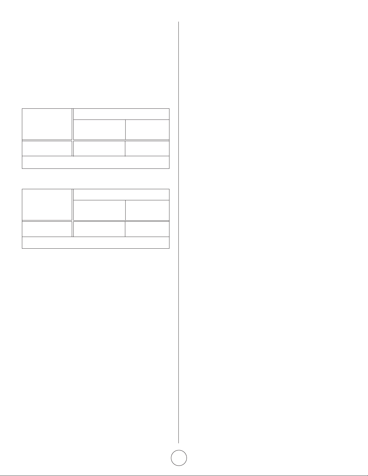
TABLE 4
NATURAL GAS MANIFOLD PRESSURES - IN.WG. (KPA)
ALTITUDE FT. (M)
MHU 50/80 0-2000 2000-4500
(0-610) (610-1370)
50/80 4.0”WC (0.99 kPa)*
3.6”WC (0.89 kPa)
*No adjustment required.
TABLE 5
LP/PROPANE GAS MANIFOLD PRESSURES - IN.WG. (KPA)
ALTITUDE FT. (M)
MHU 50/80 0-2000 2000-4500
(0-610) (610-1370)
50/80 10.5”WC (2.62 kPa)*
8.5”WC (2.12 kPa)
*No adjustment required.
LIMIT CONTROL
The limit control switch is factory set and not field adjustable.
LOUVER VANE ADJUSTMENTS
Rotate louver vanes to direct airflow upward, downward, straight,
or any combination of these directions. When unit is installed
in an inverted position, louvers may be positioned in the same
manner.
COMBUSTION AIR PRESSURE SWITCH
This pressure switch checks for proper combustion air blower
operation before allowing an ignition trial. The switch is factory set
and no field adjustment is necessary.
FLAME ROLLOUT SWITCH
The flame rollout switch(es) are located on the burner box top,
behind the ignition control board. This normally closed switch
opens on a temperature rise. Check for adequate combustion air
before manually resetting switch.
SERVICE
CAUTION Turn off gas and electrical power to unit before
performing any maintenance or service operations on this unit.
Remember to follow lighting instructions when putting unit back
into operation after service or maintenance.
If any of the original wire as supplied with the appliance must
be replaced, it must be replaced with wiring material having a
temperature rating of at least 105°C.
Do not use this appliance if any part has been under water.
Immediately call a qualified service technician to inspect the
appliance and replace any gas control which has been under
water.
BURNERS
1. Periodically examine burner flames for proper appearance
during the heating season.
2. Before each heating season examine the burners for any
deposits or blockage that may have occurred.
3. Clean burners as follows:
• Turn off both electrical and gas supplies to unit.
• Disconnect gas supply piping, high tension and sensor
leads. Remove gas manifold. Remove burner tray.
• Clean burners as necessary. Make sure that burner
heads line up properly to ensure flame crossover. Check
spark gap on electrode and adjust if required. The gap
should be between 0.110 inch and 0.140 inch (2.79mm
to 3.56mm). The gap may be checked with appropriately
sized twist drills or feeler gauges.
• Reinstall burner tray, gas manifold, high tension and
sensor leads. Reconnect gas supply piping.
• Restore electrical power and gas supply. Follow lighting
instructions to light unit. Check burner flame.
4. Clean burner filter screen as follows:
• Turn off both electrical and gas supply to unit.
• Remove the filter screen from the inlet to the burner
housing by squeezing and pulling out.
• With screen out of the heater, clean with light soap and
water or blow out with compressed air (blowing away
from you).
• Dry screen thoroughly with air and make sure all air
passages in the screen are fully opened.
• Replace screen into burner housing opening.
• Restore electrical and gas supply.
• Follow lighting instructions to light the heater. Check
burner flame.
FLUE PASSAGEWAY AND FLUE BOX
The flue passages and flue box should be inspected and cleaned
prior to each heating season. The sequence of operation should
be as follows:
1. Turn off both electrical and gas supply to unit.
2. Disconnect combustion air blower wiring.
3. Remove screws securing flue box to unit. Remove flue box. If
necessary, remove blower assembly from flue box. Clean flue
box with wire brush.
4. Remove turbulator retention bracket and turbulators. Clean
turbulators with wire brush.
5. Remove burners as described in section “BURNERS” section.
6. Clean tubes with a wire brush.
7. Reassemble unit. The combustion air and flue box gaskets
should also be replaced during reassembly.
8. Restore electrical power and gas supply. Follow lighting
instructions to light unit. Check operation of unit.
COMBUSTION AIR BLOWER
Under normal operating conditions, the combustion air blower
should be checked and cleaned prior to the heating season with
the power supply disconnected. Use a small brush to clean blower
wheel.
Compact Unit / Utility Heater Operating Instructions and Owner’s Manual
E-12
Page 13
LADDER DIAGRAM
Red
White
OPTIONAL THERMOSTAT
INSTALLATION
IT IS RECOMMENDED TO USE
18AWG WIRE WHEN INSTALLING
THE THERMOSTAT. CONNECT
THERMOSTAT WIRING TO
TERMINALS ‘R’ AND ‘W’ AS
ILLUSTRATED ON THE SCHEMATIC
DIAGRAM.
NOTE: THERMOSTAT TERMINAL
CONNECTIONS ARE MOUNTED ON
THE BACK PANEL OF THE HEATER.
EXTERNAL THERMOSTAT
TERMINAL STRIP WARNING: DO
NOT CONNECT LINE POWER TO
THE THERMOSTAT TERMINAL
STRIP.
E-13
Operating Instructions and Owner’s ManualCompact Unit / Utility Heater
Page 14
ELECTRICAL
1. Check all wiring for loose connections.
2. Check for correct voltage at unit (unit operating).
3. Check amperage draw.
FLUE AND CHIMNEY
Check all vent and vent connector joints for tightness. Ensure that
connections are sealed and that there are no blockages.
2. Is main disconnect closed?
3. Is there a breaker tripped or a fuse blown?
4. Is gas turned on at meter?
5. Is manual shutoff valve open?
6. Is unit ignition system in lock out? If unit locks out again, call
service technician to inspect unit.
7. Is pressure switch closed? Obstructed flue will cause unit to
shut off at pressure switch. Check flue passage and outlet.
FAILURE TO OPERATE
If unit fails to operate check the following:
1. Is thermostat calling for heat?
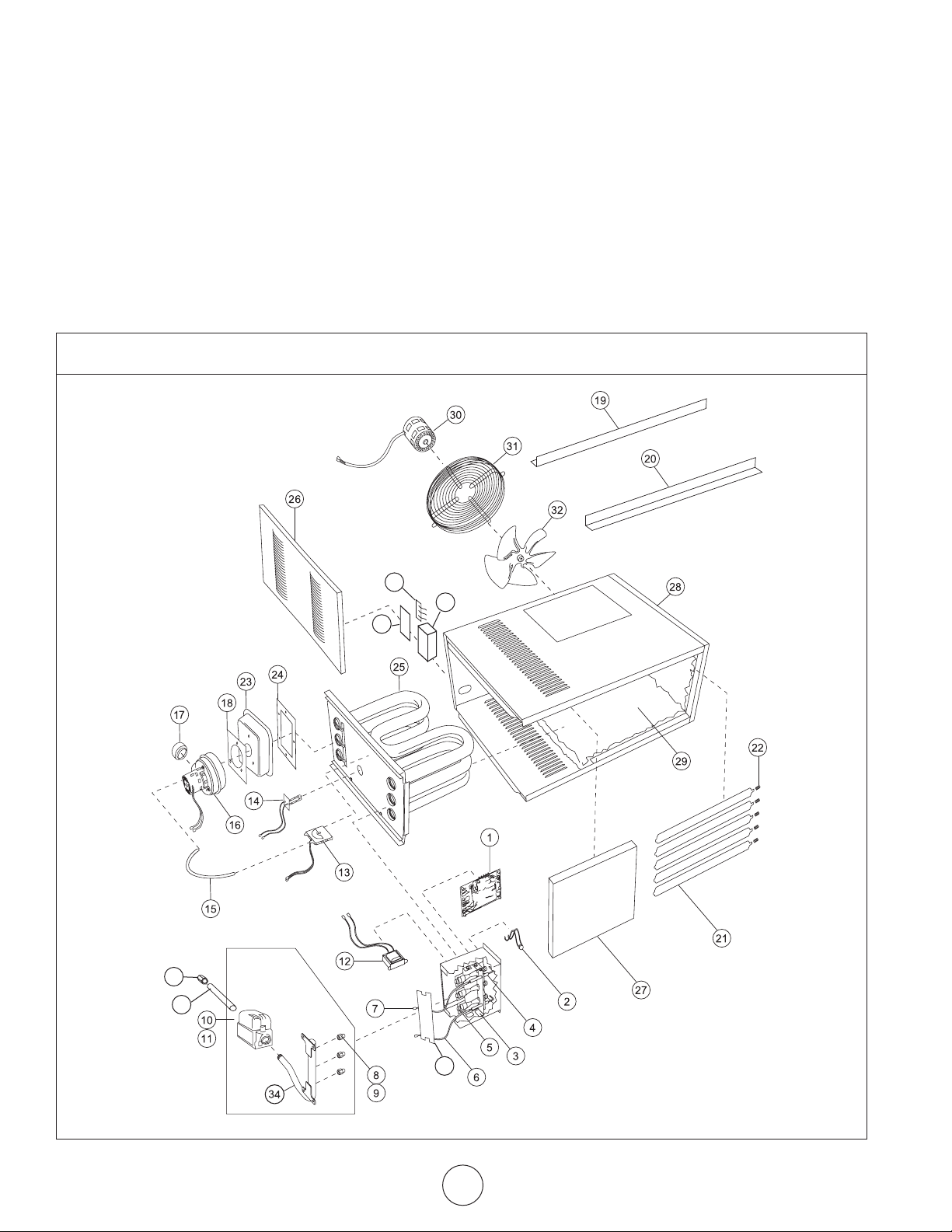
HeatStar • Compact Unit / Utility Heater • Model # MHU 50/80
REPAIR PARTS
When ordering repair parts include the complete unit model
number listed on the unit rating plate. For example: HSU50/80.
38
40
39
36
35
37
Compact Unit / Utility Heater Operating Instructions and Owner’s Manual
E-14
Page 15
PARTS LIST:
SEE BACK PAGE FOR PARTS ORDERING INFORMATION
REF #. DESCRIPTION 50 ITEM # QUANTITY 80 ITEM # QUANTITY
1.................CIRCUIT BOARD .................................................... 60105 .......................1 ....................................S/A .......................1
2.................LIMIT SENSOR ....................................................... 60022 ......................1 ....................................60021 ...................2
3.................ELECTRODE IGNITER .............................................. 60139 .......................1 ....................................S/A .......................1
4.................ELECTRODE SENSOR .............................................. 60141 .......................1 ....................................S/A ....................... 1
5.................BURNER ................................................................60155 .......................3 ....................................60191 ....................5
6.................IGNITION LEAD ..................................................... 60045 ......................1 ....................................S/A .......................1
7.................SENSOR LEAD .......................................................60046 ......................1 ....................................S/A .......................1
8.................ORIFICE (NAT) ....................................................... 60049 ......................3 ....................................S/A ....................... 5
9.................ORIFICE (LP) .......................................................... 60156 .......................3 ....................................S/A .......................5
10 ...............GAS VALVE (NAT) .................................................. 60128 .......................1 ....................................S/A .......................1
11 ...............GAS VALVE (LP) ..................................................... 60129 .......................1 ....................................S/A .......................1
12 ...............TRANSFORMER .....................................................60025 ......................1 ....................................S/A .......................1
13 ...............PRESSURE SWITCH ................................................ 60147 .......................1 ....................................60146 ...................1
14 ...............HI LIMIT SENSOR HEAT EXCH. ...............................60015 .......................1 ....................................S/A .......................1
15 ...............PRESSURE SWITCH TUBE ....................................... 60031 .......................1 ....................................S/A .......................1
16 ...............INDUCED DRAFT MOTOR ...................................... 60020 ......................1 ....................................S/A .......................1
17 ...............VENT ADAPTER ..................................................... 60130 .......................1 ....................................60140 ...................1
18 ...............INDUCED DRAFT MOTOR GASKET .........................60157 .......................1 ....................................S/A .......................1
19 ...............BACK BRACKET ....................................................60075 ......................1 ....................................S/A .......................1
20 ............... FRONT BRACKET ..................................................60080 ......................1 ....................................S/A .......................1
21 ...............LOUVERS .............................................................. 60100 .......................5 ....................................S/A ....................... 7
22 ............... LOUVER SPRING ................................................... 60103 .......................5 ....................................S/A ....................... 7
23 ............... FLUE BOX ..............................................................60189 .......................1 ....................................60190 ...................1
24 ...............FLUE BOX GASKET ................................................. 60090 ......................1 ....................................60092 ................... 1
25 ............... HEAT EXCHANGER ................................................60065 ......................1 ....................................60068 ...................1
26 ............... ACCESS DOOR ..................................................... 60070.......................1 ....................................60072 ...................1
27 ...............FRONT ..................................................................60095 ......................1 ....................................60097 ................... 1
28 ............... SIDE DOOR ..........................................................60110 .......................1 ....................................60112 ....................1
29 ............... WRAPPER .............................................................60115 ........................3 ....................................60117 ....................3
30 ............... FAN MOTOR .......................................................... 60055 ......................1 ....................................60054 ................... 1
31 ...............FAN GUARD .........................................................60120 .......................1 ....................................60122 ....................1
32 ............... FAN ASSEMBLY ..................................................... 60125 .......................1 ....................................60127 ....................1
33* ............. CAPACITOR STARTER .....................................................................................................................28788 ...................1
34 ............... MANIFOLD ............................................................60062 ......................1 ....................................60064 ...................1
35 ............... INLET PIPE ............................................................. 60132 .......................1 ....................................S/A .......................1
36 ............... INLET FITTING ....................................................... 60131 .......................1 ....................................S/A .......................1
37 ...............BURNER SCREEN ...................................................60142 .......................1 ....................................S/A .......................1
38 ............... THERMOSTAT TERMINAL .......................................60144 .......................1 ....................................S/A ....................... 1
39 ............... WIRING JUNCTION BOX ........................................ 60159 .......................1 ....................................S/A ....................... 1
40...............COVER, WIRING JUNCTION BOX ........................... 60160 .......................1 ....................................S/A .......................1
Not Shown . GAS VALVE BRACKET ............................................. 60158 .......................1 ....................................S/A .......................1
*Not Shown
Optional Installation Components
24V THERMOSTAT ..................................................................................F210359
4” VERTICAL VENT KIT (80) ....................................................................F102848
3” VERTICAL VENT KIT (50) ....................................................................F102840
4” HORIZONTAL STAINLESS STEEL VENT KIT (80) ...................................F102860
Gas Conversion Kits
Natural Gas to Liquid Propane
MHU 50/80 50,000 and 80,000 BTU ....................................F260163
Liquid Propane to Natural Gas
MHU 50/80 50,000 and 80,000 BTU ....................................F260164
Operating Instructions and Owner’s ManualCompact Unit / Utility Heater
E-15
Page 16

OPERATING INSTRUCTIONS
Model #
AND OWNER’S MANUAL
READ INSTRUCTIONS CAREFULLY: Read and follow all instructions. Place instructions in a safe
place for future reference. Do not allow anyone who has not read these instructions to assemble,
light, adjust or operate the heater.
WARNING:
USE ONLY MANUFACTURER’S REPLACEMENT PARTS. USE OF ANY OTHER PARTS
COULD CAUSE INJURY OR DEATH. REPLACEMENT PARTS ARE ONLY AVAILABLE
DIRECT FROM THE FACTORY AND MUST BE INSTALLED BY A QUALIFIED SERVICE
AGENCY.
Model Starting Serial
Number
MHU50NG LN260420-12001001
MHU50LP LN260410-12001001
MHU80NG LN260440-12001001
MHU80LP LN260430-12001001
PARTS ORDERING INFORMATION:
PURCHASING: Accessories may be purchased at any Mr. Heater local dealer or direct
from the factory
FOR INFORMATION REGARDING SERVICE
Please call Toll-Free 800-251-0001 • www.mrheater.com • www.Mr. Heater.com
Our office hours are 8:30 AM – 5:00 PM, EST, Monday through Friday.
Please include the model number, date of purchase, and description of problem in all
communication.
LIMITED WARRANTY
The company warrants this product to be free from imperfections in material or workmanship,
under normal and proper use in accordance with instructions of The Company, for a period of
three years on parts (limited) and 10 years on the heat exchanger, from the date of delivery to
the buyer. The Company, at its option, will repair or replace products returned by the buyer to
the factory, transportation prepaid within said one year period and found by the Company to
have imperfections in material or workmanship.
If a part is damaged or missing, call our Technical Support Department at 800-251-0001.
Address any Warranty Claims to the Service Department, Mr. Heater, Inc., 4560 W. 160TH ST.,
CLEVELAND, OHIO 44135. Include your name, address and telephone number and include
details concerning the claim. Also, supply us with the purchase date and the name and address
of the dealer from whom you purchased our product.
The foregoing is the full extent of the responsibility of the Company. There are no other
warranties, express or implied. Specifically there is no warranty of fitness for a particular purpose
and there is no warranty of merchantability. In no event shall the Company be liable for delay
caused by imperfections, for consequential damages, or for any charges of the expense of
any nature incurred without its written consent. The cost of repair or replacement shall be the
exclusive remedy for any breach of warranty. There is no warranty against infringement of the
like and no implied warranty arising from course of dealing or usage of trade. This warranty
will not apply to any product which has been repaired or altered outside of the factory in any
respect which in our judgment affects its condition or operation.
Some states do not allow the exclusion or limitation of incidental or consequential damages, so
the above limitation or exclusion may not apply to you. This Warranty gives you specific legal
rights, and you may have other rights which vary from state to state.
MHU 50
MHU 80
ANDIZ83.8-2009 CSA 2.6-2009
UNIT / UTILITY HEATER
CSA .10.96 U.S. (2ND ED.)
UNIT HEATER FOR RESIDENTIAL INSTALLATION
CATEGORY/CATEORIE I
Mr. Heater, Inc. reserves the right to make changes at any time, without notice or obligation, in
colors, specifications, accessories, materials and models.
PRODUCT REGISTRATION: Thank you for your purchase.
Please log in to http://www.egiregistration.com to register your product.
Mr. Heater, INC., 4560 W. 160TH ST., CLEVELAND, OHIO 44135 • 216-916-3000
Mr. Heater is a registered trademarks of Mr. Heater, Inc.
© 2003, Mr. Heater. All rights reserved
Compact Unit / Utility Heater Operating Instructions and Owner’s Manual
E-16
Page 17

INSTRUCCIONES DE USO Y
MANUAL DEL USUARIO
LEA CUIDADOSAMENTE LAS INSTRUCCIONES: lea y siga todas las instrucciones. Conserve estas
instrucciones en un lugar seguro para futura referencia. No permita que nadie que no haya leído
estas instrucciones arme, encienda, ajuste o use el calentador.
Para números de serie de los
modelos, ver la página S16.
INGLÉS
Páginas E1 — E16
ESPAÑOL
Páginas S1 — S16
Modelo N.°
MHU 50
MHU 80
IDIOMAS
CALENTADOR COMPACTO PARA USO COMERCIAL
CALENTADOR COMPACTO PARA USO RESIDENCIAL
FRANCÉS
Páginas F1 — F16
ADVERTENCIA: La instalación, el ajuste, la alteración, la reparación o el
mantenimiento indebidos pueden ocasionar daños a la propiedad o lesiones. Consulte este
manual. Para obtener ayuda o información adicional, consulte con un instalador calificado,
una agencia de reparación calificada o el suministrador de gas.
QUÉ HACER SI DETECTA OLOR A GAS
• Abra las ventanas.
• NO intente encender ningún artefacto.
• NO utilice interruptores eléctricos.
• NO utilice los teléfonos de su hogar. Llame de inmediato al suministrador de gas desde
el teléfono de un vecino. Siga las instrucciones del suministrador de gas.
• NO toque ningún interruptor eléctrico; no use ningún teléfono del edificio.
• La instalación y el mantenimiento deben ser realizados por un instalador calificado, una
agencia de reparación calificada o el suministrador de gas.
• Si no puede comunicarse con el suministrador de gas, llame al Departamento de Bomberos.
PARA SU SEGURIDAD:
No almacene ni utilice gasolina ni otros vapores y líquidos inflamables en las
proximidades de este artefacto ni de ningún otro artefacto.
ADVERTENCIA: Si no se sigue la información de estas instrucciones con exactitud,
puede producirse un incendio o una explosión y ocasionar daños a la propiedad, lesiones
personales o la muerte.
02/12 Rev. 12A #60185MR. HEATER, INC., 4560 W. 160TH ST., CLEVELAND, OHIO 44135 •800-251-0001
Page 18

ADVERTENCIA:
SU SEGURIDAD ES IMPORTANTE PARA USTED Y PARA
LOS DEMÁS. POR ELLO, LEA ESTAS INSTRUCCIONES
ANTES DE UTILIZAR EL CALENTADOR.
ADVERTENCIA GENERAL DE PELIGRO:
EL NO CUMPLIR CON LAS PRECAUCIONES E
INSTRUCCIONES QUE VIENEN CON ESTE CALENTADOR
PUEDE CAUSAR LA MUERTE, LESIONES GRAVES Y
PÉRDIDAS Y DAÑOS MATERIALES DERIVADOS DEL
PELIGRO DE INCENDIO, EXPLOSIÓN, QUEMADURAS,
ASFIXIA, ENVENENAMIENTO CON MONÓXIDO DE
CARBONO Y/O DESCARGAS ELÉCTRICAS.
SOLO LAS PERSONAS QUE ENTIENDAN Y PUEDAN
SEGUIR LAS INSTRUCCIONES DEBEN USAR O REPARAR
EL CALENTADOR.
SI NECESITA AYUDA O INFORMACIÓN ACERCA DEL
CALENTADOR, COMO MANUALES DE INSTRUCCIONES,
ETIQUETAS, ETC., PÓNGASE EN CONTACTO CON EL
FABRICANTE.
EL ESTADO DE CALIFORNIA EXIGE LAS SIGUIENTES ADVERTENCIAS:
ADVERTENCIA:
PELIGRO DE INCENDIO, QUEMADURAS, INHALACIÓN
Y EXPLOSIÓN. MANTENGA LOS COMBUSTIBLES
SÓLIDOS, TALES COMO MATERIALES DE
CONSTRUCCIÓN, PAPEL O CARTÓN, A UNA DISTANCIA
SEGURA DEL CALENTADOR. COMO SE RECOMIENDA
EN LAS INSTRUCCIONES, NUNCA USE EL CALENTADOR
EN ESPACIOS QUE CONTENGAN O PODRÍAN
CONTENER COMBUSTIBLES VOLÁTILES O GASEOSOS,
NI PRODUCTOS COMO GASOLINA, SOLVENTES,
DILUYENTES DE PINTURA, PARTÍCULAS DE POLVO O
PRODUCTOS QUÍMICOS DESCONOCIDOS.
ADVERTENCIA: Uno de los elementos generados por la combustión al usar este equipo es monóxido de
carbono, un producto químico que de acuerdo con el estado de California produce cáncer y defectos de nacimiento
(u otros daños reproductivos).
ADVERTENCIA: Este producto contiene sustancias químicas, incluyendo plomo, conocido en el estado de
California por causar cáncer y defectos de nacimiento u otros daños reproductivos. Lávese las manos después de manipular.
CONTENIDO
DIMENSIONES DE LA UNIDAD ...............................................S-4
ENVÍO....................................................................................S-5
REQUISITOS ...........................................................................S-5
INSTALACIÓN DEL CALENTADOR ...........................................S-6
AIRE DE COMBUSTIÓN Y VENTILACIÓN ................................S-6
VENTILACIÓN .................................................................S-6-S-10
CONEXIONES ELÉCTRICAS ................................................... S-10
CONEXIÓN DE GAS ..............................................................S-11
VERIFICACIÓN DE FUGAS .....................................................S-11
OPERACIÓN DE ENCENDIDO .................................................S-11
SECUENCIA OPERATIVA DE CALEFACCIÓN ........................... S-12
LED DEL CONTROL DE IGNICIÓN ......................................... S-12
AJUSTES .............................................................................. S-12
MANTENIMIENTO ................................................................ S-13
DIAGRAMA DE CABLEADO .................................................. S-14
LISTA DE PIEZAS ..................................................................S-14
GARANTÍA ........................................................................... S-16
Unidad compacta/Calentador Instrucciones de uso y manual del usuario
S-2
Page 19

PARA COLGAR
FLUJO
DE AIRE
INTERCAMBIADOR DE CALOR
(ACERO ALUMINIZADO)
DIMENSIONES DE LAS UNIDADES MHU 50/MHU 80
(N-GAS NATURAL, P-PROPANO)
SOPORTES
RANURAS DE MONTAJE (características)
8 x 76 mm (5/16 x 3 pulgadas)
DIMENSIÓN 50 80
A 12 (305) 17 (432)
B 5-1/2 (140) 6-1/2 (165)
C 4-1/4 (108) 6-3/4 (171)
VISTA SUPERIOR
ENTRADAS
ELÉCTRICAS
VENTILADOR DE
PROPULSIÓN DIRECTA
SALIDA DE GAS
DE COMBUSTIÓN
ENTRADA
DE GAS
VISTA POSTERIOR
LISTA DE CONTROL PARA ENCENDIDO Y FUNCIONAMIENTO
Nombre del trabajo: __________________________________
Lugar del trabajo: ____________________________________
Instalador: __________________________________________
N.º de modelo de la unidad: ____________________________
¿Las conexiones eléctricas están ajustadas? ___________________________________
Voltaje de suministro ______________________________________________________
¿Se comprobó que las conexiones de tuberías estén ajustadas y sin fugas? __________
Amperaje del motor ______________________________________________________
Potencia en Btu de la calefacción ____________________________________________
Presión de línea __________________________________________________________
Presión de colector w.c. ___________________________________________________
N.º de trabajo: _________________________________
Ciudad: _______________________________________
Ciudad: _______________________________________
N.º de serie: ___________________________________
SOPORTES
PARA COLGAR (2)
BOCAS DE VENTILACIÓN
PANEL DE ACCESO
PARA MANTENIMIENTO
AJUSTABLES
VISTA LATERAL
Fecha: _____________________________________
Estado/Provincia: _____________________________
Estado/Provincia: _____________________________
Técnico de reparación: ________________________
¿Las conexiones de gas de combustión están ajustadas? ________________________
¿Se revisó el funcionamiento del temporizador del ventilador? ___________________
TERMOSTATO
¿Está calibrado? _________________________________________________________
¿El anticipador de calor está instalado correctamente?
¿Nivel? ________________________________________________________________
Unidad compacta/Calentador
Instrucciones de uso y manual del usuario
S-3
Page 20

ENVÍO
El calentador se entrega completamente ensamblado. Incluye
instrucciones, dos soportes de montaje (se entregan sueltos) y
un accesorio de transición para gas de combustión. Controle que
la unidad no se haya dañado durante el envío. Si el destinatario
detecta daños por el envío, deberá comunicarse de inmediato con
el último transportista.
REQUISITOS – CSA EN EE. UU.
La instalación de calentadores a gas debe cumplir con los códigos
de construcción locales o, si no existieran dichos códigos, con el
Código Nacional de Gas Combustible ANSI Z223.1 vigente.
La instalación en hangares debe cumplir con la Norma para
Hangares ANSI/NFPA N.º 409 vigente.
La instalación en edificios de estacionamiento debe cumplir con
la Norma para Edificios de Estacionamiento ANSI/NFPA N.º 88A
vigente.
La instalación en talleres de reparación debe cumplir con la Norma
para Talleres de Reparación ANSI/NFPA N.º 88B vigente.
Estas unidades están aprobadas para uso residencial. Para la
instalación en garajes residenciales, las unidades se deben
instalar de modo tal que los quemadores y la fuente de ignición
se encuentren a no menos de 2,438 m (8 pies) sobre el piso. El
calentador se debe ubicar o proteger de modo tal que se eviten
daños físicos causados por vehículos. Consulte la edición vigente
del Código Nacional de Gas Combustible ANSI Z223.1.
Antes de realizar una instalación conforme a la NFPA, se debe
consultar a las autoridades que tengan jurisdicción. El aire para
la combustión y ventilación debe cumplir con los métodos
especificados en la norma ANSI Z223.1, sección 5.3, Aire para la
Combustión y Ventilación, o en las disposiciones pertinentes de
los códigos de construcción locales. El Código Nacional de Gas
Combustible se encuentra disponible en:
American National Standard Institute Inc.
11 West 42nd Street
New York, NY 10036
El diseño de las unidades está certificado por CSA International.
Los calentadores están certificados para su instalación en material
combustible, como se detalla en la tabla 1 y en la placa de
especificaciones de la unidad. Se deben respetar los espacios libres
para el acceso, el mantenimiento y la protección contra incendios.
Todo el cableado eléctrico y la conexión a tierra de la unidad
deben realizarse de acuerdo con las normativas del Código
Eléctrico Nacional vigente ANSI/N.º 70.
El Código Eléctrico Nacional se encuentra disponible en:
National Fire Protection Association
1 Batterymarch Park
PO Box 9101
Quincy, MA 02269-9101
TABLA 1
DISTANCIAS DE LA UNIDAD
Parte superior Lados Panel de acceso
pulgadas mm pulgadas mm pulgadas mm
1 25 1 25 18 457
Parte inferior Parte posterior Ventilación monocapa*
pulgadas mm pulgadas mm pulgadas mm
0 0 18 456 6 152
* Excepto para distanciadores tubulares homologados.
REQUISITOS – CSA EN CANADÁ
Las instrucciones sólo constituyen una guía general y no reemplazan
de modo alguno los códigos locales. Antes de la instalación,
se debe consultar a las autoridades que tengan jurisdicción. La
instalación debe cumplir con los códigos de construcción locales o,
si no existieran dichos códigos, con el Código de Instalación de Gas
Natural y Propano CSA B149.1. vigente. Todo el cableado eléctrico
y la conexión a tierra de la unidad también deben cumplir con la
edición vigente del Código Eléctrico Canadiense CSA C22.1.
Estos calentadores cuentan con la certificación de CSA International
con respecto a las distancias a material combustible que figuran
en la placa de especificaciones y en la tabla 1. Distancia adecuada
alrededor de las aberturas de aire que conducen a la cámara
de combustión, distancia desde el material combustible, y
disposiciones relacionadas con la accesibilidad y el suministro de
aire para combustión y ventilación. Estas disposiciones se deberán
tener en cuenta a fin de garantizar el acceso para realizar las
tareas de mantenimiento del calentador. Tenga en cuenta que las
distancias de protección contra incendios pueden ser mayores a las
especificadas para proporcionar espacio adicional a fin de garantizar
el mantenimiento y el acceso a la unidad.
INSTALACIONES EN GARAJE:
La instalación en edificios de estacionamiento debe cumplir con
la Norma para Edificios de Estacionamiento ANSI/NFPA N.º 88A
vigente.
La instalación en talleres de reparación debe cumplir con la Norma
para Talleres de Reparación ANSI/NFPA N.º 88B vigente.
1. En áreas de almacenamiento, la distancia de los calentadores
con respecto a materiales combustibles debe ser tal que el
material no alcance una temperatura superior a 71 oC (160 oF)
por el funcionamiento continuo de la unidad.
2. Se debe mantener una distancia mínima de ocho pies entre el
piso y la parte inferior del calentador. Consulte el Código de
Instalación de Gas Natural y Propano CSA B149.1.
HANGAR:
La instalación de calentadores a gas debe cumplir con los códigos
de construcción locales o, si no existieran dichos códigos, con el
Código Nacional de Gas Combustible ANSI Z223.1 vigente.
1. En áreas donde se guarden aeronaves o se haga
mantenimiento de ellas, se debe mantener una distancia
mínima de 3 m (10’) entre la superficie más alta de la
aeronave y la parte inferior del calentador.
2. En las otras áreas, se debe mantener una distancia mínima de
2,44 m (8’) entre el piso y la parte inferior del calentador.
3. Los calentadores se deben ubicar de modo tal que se eviten
daños causados por aeronaves y otros artefactos necesarios
para el mantenimiento de éstas. Consulte los requisitos de las
autoridades pertinentes.
Unidad compacta/Calentador Instrucciones de uso y manual del usuario
S-4
Page 21

Estas unidades están aprobadas para uso residencial. Para la
instalación en garajes residenciales, las unidades se deben
instalar de modo tal que los quemadores y la fuente de ignición
se encuentren a no menos de 457 mm (18”) sobre el piso. El
calentador se debe ubicar o proteger de modo tal que se eviten
daños físicos causados por vehículos. Consulte la edición vigente
del Código de Instalación de Gas Natural y Propano CSA B149.1.
En áreas cerradas, el calentador se debe instalar de acuerdo con
el Código de Instalación de Gas Natural y Propano CSA B149.1.
Asegúrese de cumplir con los requisitos adicionales de los códigos
y ordenanzas locales.
INSTALACIÓN DEL CALENTADOR
La unidad se entrega lista para su instalación. La unidad se puede
instalar como se muestra en la figura 1 o invertida 180o según
la ubicación deseada y los requisitos de distancia, conexión de
ventilación, dirección del aire, suministro de gas, suministro
eléctrico y acceso para el mantenimiento.
1. Si instala la unidad en posición invertida, realice lo siguiente:
Retire y guarde los tornillos que fijan la puerta, y gire la puerta
180o. Fije la puerta con los tornillos guardados. Gire las bocas
de ventilación para dirigir el flujo de aire según lo desee.
2. Elija la ubicación para los soportes de montaje.
3. Retire y guarde los tres tornillos del borde superior (borde
inferior si se invierte) del frente de la unidad.
4. Alinee los orificios para tornillos del soporte de montaje con los
orificios del borde superior (o invertido) de la unidad. Fije un
soporte de montaje a la parte delantera de la unidad con los
tornillos guardados. Fije el otro soporte de montaje a la parte
posterior de la unidad con los tornillos suministrados en el
ensamble de bolsa que contiene el accesorio de transición para
gas de combustión.
5. Para sostener la unidad, fije el soporte de montaje a una viga o
tirante del techo. La unidad también se puede colgar de varillas
como se muestra en la figura 1.
FIGURA 1
INSTALACIÓN DE LA UNIDAD / CALENTADOR
SOPORTES
DE MONTAJE (2)
VARILLAS
DE SOSTÉN
Código Nacional de Gas Combustible ANSI Z223.1, en EE. UU., el
Código de Instalación de Gas Natural y Propano CSA B149.1, o las
disposiciones pertinentes de los códigos de construcción locales.
Todos los artefactos a gas necesitan aire para usar en el proceso
de combustión. En muchos edificios actuales, hay presión de
aire negativa en el interior producida por extractores, etc. Si no
se dispone de la cantidad suficiente de aire de combustión, el
calentador y otros artefactos no funcionarán en forma eficiente,
lo que causará una combustión incompleta y podrá generar un
exceso de monóxido de carbono.
AVISO El aire de combustión insuficiente puede causar dolor de
cabeza, náuseas, mareos, asfixia o la muerte.
Si para la combustión se utiliza aire del interior, éste debe estar
libre de las siguientes sustancias o la vida útil del intercambiador
de calor podría verse afectada negativamente: cloro, tetracloruro
de carbono, solvente de limpieza, refrigerantes halógenos, ácidos,
colas y pegamentos, tintas de impresión, fluoruros, quitapinturas,
barnices u otros corrosivos.
VENTILACIÓN
A – REQUISITOS Y RECOMENDACIONES
GENERALES
NOTA: La ventilación es un paso vertical o casi vertical que
se utiliza para transportar los gases de combustión desde un
artefacto, o su conector de ventilación, hacia la atmósfera exterior.
El conector de ventilación es el tubo o conducto que conecta el
artefacto que quema gas o combustible con una ventilación o
chimenea.
La ventilación de los calentadores debe cumplir con todos
los códigos locales o requisitos de la empresa de servicios
públicos local, las normas vigentes del Código Nacional de Gas
Combustible (de EE. UU.) ANSI Z223.1 o el Código de Instalación
de Gas Natural y Propano (de Canadá) CSA B149.1, y las siguientes
instrucciones.
Con la unidad certificada se incluye un accesorio de transición
extrudido/estampado en metal. Éste no se debe modificar ni
alterar y se debe instalar en la salida del ensamble del soplador
de tiro inducido antes de instalar la ventilación o el conector
de ventilación. El incumplimiento de este requisito anulará
la certificación de la unidad por los organismos reguladores.
Todas las juntas se deben asegurar con, al menos, dos tornillos
anticorrosivos. Después de la instalación, se debe comprobar que
todas las juntas queden herméticas para evitar la fuga de gas.
AIRE DE COMBUSTIÓN Y VENTILACIÓN
Se deben proporcionar instalaciones adecuadas para suministrar
aire de combustión y ventilación de acuerdo con la última edición
de la sección 5.3, Aire para la Combustión y Ventilación, del
Unidad compacta/Calentador
TABLA 2
LONGITUDES MÁXIMAS DE VENTILACIÓN
VENTILACIONES HORIZONTALES
Cant. de Pies m
codos
1 25 7.6
2 20 6.1
3 15 4.6
4 10 3.0
5 5 1.5
La longitud máxima del conector de ventilación no debe superar
los 9,1 m (30 pies).
Instrucciones de uso y manual del usuario
S-5
Page 22

B – VENTILACIONES VERTICALES CON TUBO
DE VENTILACIÓN METÁLICO - INSTALACIONES
COMERCIALES Y RESIDENCIALES
Los calentadores compactos MHU están clasificados como
artefactos de Categoría I para instalaciones con ventilación vertical.
1. Los calentadores MHU se deben utilizar con chimeneas
aprobadas por NFPA o ANSI, ventilaciones de gas tipo B-1
homologadas por U.L., tubos de metal monocapa o un
sistema de revestimiento de chimenea homologado para
ventilación de gas donde corresponda, además de las
modificaciones y limitaciones que se detallan en la figura 2.
Selle el material de ventilación monocapa de acuerdo con la
sección A - Requisitos y recomendaciones generales.
2. El conector de ventilación tendrá un diámetro de 76 mm (3”)
en unidades 50. En todos los casos, se necesita una pieza de
transición para el gas de combustión (incluida) que deberá
colocarse en la salida del conjunto de tiro inducido del equipo.
3. Mantenga el tendido del conector de ventilación lo más corto
posible con una mínima cantidad de codos. Para conocer las
longitudes máximas de ventilación y conectores de ventilación,
consulte el Código Nacional de Gas Combustible (de EE. UU.)
ANSI Z223.1 o el Código de Instalación de Gas Natural y Propano
(de Canadá) CSA B149.1. El tendido horizontal del conector de
ventilación entre el soplador de tiro inducido y la chimenea o
ventilación no debe superar los valores de la tabla 2.
4. Si la longitud de una ventilación monocapa, incluidos los
codos, supera los 1,5 m (5 pies), la ventilación se deberá
aislar en toda su longitud con un aislamiento de densidad
1-1/2# con fibra de vidrio revestida con láminas de aluminio
de 1,3 cm (1/2”) de espesor. Si se utiliza una ventilación
monocapa en un área no calefaccionada, debe estar aislada.
De lo contrario, se condensarán los gases de combustión.
5. La unidad puede tener una ventilación vertical como artefacto
único o una ventilación común con otros artefactos a gas. En
caso de ventilación común, los conectores de ventilación de
los otros artefactos deben mantener una separación vertical
de 100 mm (4”) entre sí. Para conocer el tamaño correcto
de la ventilación, consulte las tablas de ventilación común
del Código Nacional de Gas Combustible (de EE. UU.) ANSI
Z223.1 o el Código de Instalación de Gas Natural y Propano
(de Canadá) CSA B149.1.
6. La distancia de materiales combustibles para materiales de
ventilación monocapa es de 152 mm (6”), excepto donde
se utilice un distanciador tubular homologado. La distancia
de materiales combustibles para ventilaciones tipo B-1 o
chimeneas de fábrica es la especificada por el fabricante.
7. El conector de ventilación debe sujetarse sin inclinación ni
pandeo. Las ventilaciones verticales se deben sujetar de
acuerdo con las instrucciones homologadas y del fabricante.
Todo el tendido horizontal del conector de ventilación debe
tener una pendiente ascendente hacia la ventilación vertical
de, al menos, 1 mm por cada 50 mm (1/4” por pie).
8. Todas las ventilaciones verticales tipo B-1, ventilaciones
monocapa o sistemas de revestimiento de chimenea
homologados se deben terminar con una tapa de ventilación
o un ensamble para techo homologados.
9. La ventilación debe prolongarse, al menos, 1 m (3’) por
encima del punto más alto donde atraviese el techo del
edificio y al menos 0,6 m (2’) por encima de cualquier parte
del edificio que se encuentre a una distancia horizontal de
3,05 m (10’), excepto que se especifique de otro modo en
el Código Nacional de Gas Combustible (de EE. UU.) ANSI
Z223.1 o en el Código de Instalación (de Canadá) CAN/
CGA-B149. La ventilación debe prolongarse, al menos, 1,6 m
(5’) por encima del anillo de gas de combustión del equipo
que esté conectado más alto.
FIGURA 2
C – VENTILACIÓN HORIZONTAL – GENERAL
Debido a cambios efectuados en Z83-8 2009 CSA2.6-2009,
ya no se permite el uso de una ventilación B de pared simple
como material aceptable para hacer ventilaciones horizontales.
Este cambio abarca tanto las instalaciones residenciales como
las comerciales. A todas las unidades con ventilación horizontal
fabricadas después de julio de 2011, se les debe hacer la ventilación
de la Unidad/el Calentador de Categoría III, de acuerdo con UL
1738 & ULS636. No están permitidas las ventilaciones comunes
cuando se utiliza la ventilación horizontal en los calentadores.
La longitud de ventilación horizontal mínima es de 914 mm (3 pies).
1. De ser posible, no haga la terminación de una ventilación
horizontal a través de una pared que esté expuesta a vientos
constantes. La exposición a vientos excesivos puede afectar el
rendimiento de las unidades.
2. La terminación de la ventilación debe estar libre de
obstrucciones y por lo menos a 306 mm (12”) sobre el nivel
de la base y la altura de nieve máxima.
3. No haga la terminación de la ventilación directamente
debajo de los aleros del techo o sobre una pasarela, ni en
cualquier otra área donde el goteo de condensado pueda
provocar manchas. Evite las ventanas donde el vapor pueda
empañarlas o donde se pueda formar hielo.
4. Al hacer ventilaciones horizontales, la distancia mínima para
la terminación a cualquier puerta, ventana, entrada de aire,
gas o medidor eléctrico, reguladores y equipos de liberación
es de 1,2 m (4 pies) para las instalaciones en los Estados
Unidos. Consulte NFPA 54/ANSI Z223.1 en los Estados
Unidos de América y CSA B149.1 Código de instalación de
propano y gas natural y .2 en Canadá, o a autoridades que
tengan jurisdicción local. En Canadá, las terminaciones de la
ventilación deben tener una distancia horizontal mínima
de 1,8 m (6 pies) desde los medidores eléctricos y de gas, y
Unidad compacta/Calentador Instrucciones de uso y manual del usuario
S-6
Page 23

de los dispositivos de liberación como se especifica en B149.1,
del Código canadiense de instalación de gas natural.
5. La terminación de la ventilación debe estar a un mínimo
de 1,2 m (4 pies) debajo de toda ventilación de paneles de
sofito o ventilación que haya debajo de aleros, o bien a 1,2 m
(4 pies) en posición horizontal.
6. La ventilación debe estar a un mínimo de 1,8 m (6 pies) de
la esquina interior formada por dos paredes exteriores. Si es
posible, deje una distancia de 4 m (10 pies).
7. La terminación de la ventilación debe estar a por lo menos 3 m
(10 pies) de toda entrada de aire forzado (incluida la entrada
de aire fresco para otros dispositivos, como un secador).
8. Cuando una terminación se pasa a través de una pared
combustible exterior, se debe sostener la ventilación con un
casquillo de distancia, que se encuentra incluido en la lista.
Selle la conexión que hay entre los tubos de una pared simple
y una pared doble y el espacio anular del tubo de la pared
doble, como se muestra en la figura 2. El borde interior de la
junta de terminación en T de la ventilación debe estar a un
mínimo de 30,48 cm (12 pulgadas) de la pared exterior, como
se muestra en la figura 3.
9. Para la ventilación horizontal, el tubo de ventilación debe
estar agarrado con ganchos ubicados a una distancia máxima
de 1 m (3 pies) entre sí para evitar que se mueva después de
la instalación.
D – VENTILACIÓN HORIZONTAL – COMERCIAL
1. Las instalaciones comerciales horizontales son para edificios
que no estén pegados a espacios habitados. La ventilación
puede ser material de ventilación de pared simple instalado
de acuerdo con las secciones
Ventilación A: recomendaciones y requisitos generales
y C - Ventilación horizontal: general y D - Ventilación
horizontal: comercial. Consulte la figura 3.
2. El diámetro del tubo de ventilación de las instalaciones
comerciales horizontales será de 76 mm (4 pies) en unidades
50. En todos los casos, se necesita una pieza de transición para
el gas de combustión (incluida) que deberá colocarse en la
salida del conjunto de tiro inducido del equipo.
3. Consulte la tabla 2 para conocer las longitudes máximas de
los conectores de ventilación.
4. Seleccione una punta de terminación de pared que mantenga
una pendiente de incremento de 0,64 cm (¼”) por pie de
longitud horizontal del caño de ventilación.
5. Para la ventilación de pendiente vertical, se debe instalar
una junta de condensado en T dentro de los primeros 1,5 m
(5 pies) desde el calentador para proteger el aparato. Si se
utiliza una línea de drenaje de condensado flexible, esta debe
incluir una presilla en el ingreso a la estructura. Si la unidad
se apaga por un período prolongado y si va a estar expuesta
a temperaturas inferiores al punto de congelamiento, es
posible que el condensado se congele.
E – VENTILACIÓN HORIZONTAL – RESIDENCIAL
1. Para instalaciones residenciales horizontales, estas unidades
cuentan con la certificación de dispositivos de Categoría III.
Ventilación A: recomendaciones y requisitos generales
y C: Ventilación horizontal: general y E: Ventilación
horizontal: residencial. Consulte la figura 6.
2. El diámetro del tubo de ventilación para instalaciones
residenciales horizontales será de 100 mm (4”) en unidades
50 y 80. Se requiere una transición de ventilación estándar en
la unidad además de la transición incluida con la unidad.
3. La longitud máxima de la ventilación es 1,5 m (5 pies) más un
codo de 90 grados. La longitud mínima es de 0,91 m (3 pies).
4. La ventilación debe mantener una pendiente de incremento
de 0,635 cm (¼”) por pie vertical hacia la terminación.
DRENAJE DE CONDENSADO A TRAVÉS DE TUBO EN T Y BUCLE DE DRENAJE
PENDIENTE ASCENDENTE EN VENTILACIÓN HORIZONTAL - INSTALACIÓN COMERCIAL
VENTILACIÓN DE CATEGORÍA III DE ACUERDO CON ESTAS INSTRUCCIONES DE INSTALACIÓN
PENDIENTE: LONGITUD MÍNIMA DE + 0,6 cm por 30 cm (1/4 DE PULGADA POR 1 PIE)
SOPLADOR DE TIRO
INDUCIDO
NOTA: LONGITUD HORIZONTAL MÍNIMA 914 MM (3 PIES),
SIN INCLUIR TAPA DE TERMINACIÓN. CONSULTE LA TABLA
2 PARA VER LONGITUD MÁXIMA Y C ANTIDAD DE CODOS.
NO SE PERMITE LA VENTILACIÓN COMÚN CUANDO SE HACE UNA VENTILACIÓN HORIZONTAL EN LA UNIDAD/CALENTADOR.
ACCESORIO DE TRANSICIÓN
PARA GAS DE COMBUSTIÓN
(SUMINISTRADO)
DISTANCIADOR
HOMOLOGADO
A TRAVÉS DE PARED
COMBUSTIBLE
BUCLE DE DRENAJE CON SEPARADOR DE
AGUA (A DRENAJE DE CONDENSADO)
FIGURA 3
30,5 CM MÍN.
(12 PULGADAS)
ESCAPE ETE FIN DE
VENTILACIÓN
30,5 CM (12”)
MÍNIMO SOBRE EL
MÁXIMO NIVEL DE NIEVE
Unidad compacta/Calentador
Instrucciones de uso y manual del usuario
S-7
Page 24

SOPLADOR DE TIRO INDUCIDO
VENTILACIÓN DE CATEGORÍA III DE ACUERDO CON ESTAS
INSTRUCCIONES DE INSTALACIÓN
PENDIENTE: LONGITUD MÍNIMA DE +
(1/4 DE PULGADA POR UN PIE)
NOTA: LONGITUD HORIZONTAL MÍNIMA 914 MM (3 PIES),
SIN INCLUIR TAPA DE TERMINACIÓN.
LONGITUD HORIZONTAL MÁXIMA 1,5 M (5 PIES) MÁS UN
CODO DE 90 GRADOS.
SI LA VENTILACIÓN DEL CALENTADOR ES HORIZONTAL, NO SE PERMITE UNA VENTILACIÓN COMÚN.
VENTILACIÓN HORIZONTAL - INSTALACIÓN RESIDENCIAL
ACCESORIO DE TRANSICIÓN
PARA GAS DE COMBUSTIÓN
(SUMINISTRADO)
DISTANCIADOR HOMOLOGADO A
TRAVÉS DE PARED COMBUSTIBLE
0,6 cm por 30 cm
.
PENDIENTE ASCENDENTE
30,5 CM MÍN.
(12 PULGADAS)
TAPA DE TERMINACIÓN DE
VENTILACIÓN
FIGURA 6
F – VENTILACIÓN CON UNA CHIMENEA DE
MAMPOSTERÍA
Los siguientes requisitos adicionales se aplican cuando se utiliza una
chimenea de mampostería revestida para ventilar el calentador.
1. Las chimeneas de mampostería usadas para ventilar calentadores
de Categoría I deben estar revestidas con azulejos, con un
sistema de revestimiento metálico homologado o con una
ventilación de gas dedicada. Las chimeneas de mampostería
sin revestimiento están prohibidas. Los artefactos de Categoría I
nunca deben conectarse a una chimenea usada para un artefacto
de combustible sólido. Si se utiliza la chimenea de un hogar, se
deberá sellar en forma permanente la abertura del hogar.
2. Un calentador asistido por ventilador podrá usar una ventilación
común a través de una chimenea de mampostería revestida
siempre y cuando se cumplan los siguientes requisitos:
• La chimenea se utiliza actualmente para, al menos, un
artefacto equipado con campana extractora.
• El tamaño del conector de ventilación y la chimenea es
el especificado en las tablas de ventilación del Código
Nacional de Gas Combustible (de EE. UU.) ANSI Z223.1
o el Código de Instalación de Gas Natural y Propano
(de Canadá) CSA B149.1.
IMPORTANTE: La ventilación de un calentador asistido por ventilador a
través de una chimenea de mampostería revestida con azulejos (pared
interior o exterior) para un solo artefacto está prohibida. Primero,
la chimenea debe estar revestida con una ventilación tipo B-1 o un
sistema de revestimiento monocapa flexible y aislado para ventilación,
con el tamaño especificado en las tablas de ventilación del Código
Nacional de Gas Combustible (de EE. UU.) ANSI Z223.1 o el Código de
Instalación de Gas Natural y Propano (de Canadá) CSA B149.1.
3. La ventilación tipo B-1 o el revestimiento de la chimenea de
mampostería deben terminar por encima de la superficie
del techo con una tapa o ensamble de tapa homologado de
acuerdo con las condiciones de su respectiva homologación y
las instrucciones del fabricante de la ventilación.
4. No instale un regulador de tiro manual, un regulador de tiro
barométrico o un reductor de gases de combustión entre el
calentador y la chimenea.
5. Si se utiliza una ventilación bicapa tipo B-1 dentro de la
chimenea, no se podrá ventilar ningún otro artefacto en ésta.
La pared exterior del tubo de ventilación tipo B-1 no se debe
exponer a productos de combustión.
6. El aislamiento del tubo de ventilación flexible debe ser una
funda de fibra de vidrio encapsulada recomendada por el
fabricante del tubo de ventilación.
7. El espacio entre el revestimiento y la chimenea NO se debe
aislar con mica expandida ni con ningún otro material aislante
con gránulos sueltos.
8. Si no se puede usar una ventilación tipo B-1 o un tubo de
ventilación flexible aislado como revestimiento, se deberá
reconstruir la chimenea para incorporar uno de estos métodos, o
se deberá hallar otro método aprobado alternativo para ventilar
el artefacto. Si la inspección revela que la chimenea existente
no es segura para el fin previsto, deberá ser reconstruida para
cumplir con las normas reconocidas a nivel nacional, revestida
o vuelta a revestir con materiales adecuados o reemplazada
con una ventilación o chimenea de gas apta para ventilar
calentadores. El paso de la chimenea se deberá revisar
periódicamente para asegurar que esté libre y sin obstáculos.
G – QUITAR LA UNIDAD DE UNA
VENTILACIÓN COMÚN
Si se quita un calentador existente de un sistema de ventilación que se
usa comúnmente con otros artefactos a gas, es posible que el sistema
de ventilación sea demasiado grande para ventilar adecuadamente el
resto de los artefactos instalados. Se deberá realizar la siguiente prueba
con cada artefacto mientras uno está en funcionamiento y el resto
apagado, pero conectado al sistema de ventilación común. Si el sistema
de ventilación se instaló de forma incorrecta, se deberá corregir.
1. Selle todas las aberturas no utilizadas del sistema de
ventilación común.
2. Inspeccione visualmente el sistema para verificar que tenga
el tamaño y el declive correctos. Determine que no haya
obstrucción o restricción, fugas, corrosión u otras fallas que
puedan causar una situación insegura.
3. De ser posible, cierre todas las puertas y ventanas del edificio
y todas las puertas entre el espacio en el que se encuentran
los artefactos que permanecen conectados al sistema de
ventilación común y los otros espacios del edificio. Encienda
las secadoras de ropa y todos los artefactos no conectados al
sistema de ventilación común. Encienda los extractores, tales
como campanas y extractores de baño, para que funcionen a
máxima velocidad. No encienda extractores de verano. Cierre
los reguladores de tiro de hogares.
Unidad compacta/Calentador Instrucciones de uso y manual del usuario
S-8
Page 25

CABLEADO DEL INDUCTOR DE VOLTAJE DE LÍNEA
UNIDAD
L1
N
CONEXIÓN A
TIERRA
DEL EQUIPO
CABLE NEGRO CON CINTA BLANCA O
CABLE BLANCO SIN CINTA
NEGRO
NEGRO
BLANCO
BLANCO
FIGURA 7
CONEXIÓN DEL SUMINISTRO DE GAS
DE CIERRE PRINCIPAL MANUAL
EMPALME CON
PUESTA A TIERRA
MACHO DE ROSCAR
1/8 NPT
COLUMNA DE
CONDENSADO
VÁLVULA
(SUMINISTRADA POR INSTALADOR)
FLUJO DE GAS
FIGURA 8
SUMINISTRO DE GAS PARA CALENTADOR
LA VÁLVULA DE CIERRE
PRINCIPAL MANUAL NO RESISTE
LA PRESIÓN DE PRUEBA
NORMAL
TAPA
CALENTADOR
VÁLVULA DE GAS
AISLADA
FIGURA 9
4. Siga las instrucciones de encendido. Ponga en funcionamiento
el artefacto a inspeccionar. Ajuste el termostato de modo que
el artefacto funcione continuamente.
5. Verifique que no haya derrame en la abertura de alivio
de la campana extractora luego de cinco minutos de
funcionamiento del quemador principal. Utilice la llama de un
fósforo o vela, o el humo de un cigarro, cigarrillo o pipa.
6. Luego de determinar que todos los artefactos conectados al
sistema de ventilación común ventilan correctamente en la
prueba que se describe arriba, regrese a su estado anterior
las puertas, ventanas, extractores, reguladores de tiro de
hogares y demás artefactos que queman gas.
7. Si se observa una ventilación inadecuada durante algunas
de las pruebas anteriores, se deberá corregir el sistema de
ventilación común. El tamaño del sistema de ventilación
común se deberá modificar para observar el tamaño
mínimo especificado en las tablas correspondientes del
Apéndice G de las normas vigentes del Código Nacional
de Gas Combustible ANSI Z223-1, en EE. UU., y en las
correspondientes tablas de tamaños para ventilación de
artefactos a gas natural y propano de Categoría I de las
normas vigentes del Código de Instalación de Gas Natural y
Propano de Canadá CSA B149.1.
NOTA: Los códigos locales pueden reemplazar cualquiera de las
disposiciones anteriores.
CONEXIONES ELÉCTRICAS
NOTA Los calentadores de serie MHU utilizan un sistema de
encendido por chispa directa. No es necesario un piloto, ya que la
chispa enciende el quemador principal siempre que la válvula de gas
esté abierta. El panel de control de encendido por chispa directa
emite ruido de radio durante el encendido del quemador.
Es posible que el nivel de energía sea necesario para perturbar un
circuito lógico de un termostato controlado por microprocesador.
Se recomienda usar un relevador de aislamiento al conectar el
calentador a un termostato controlado por microprocesador.
Seleccione la protección del circuito y el tamaño de los cables
de acuerdo a la placa de especificaciones de la unidad. Instale
un interruptor de desconexión separado (protegido tanto por
un fusible o llave general) cerca de la unidad para que pueda
desconectarse la alimentación para hacer mantenimiento. Quite
la tapa de la caja de conexiones y conecte los cables a través del
troquel de la caja de conexiones ubicada a un lado del calentador.
Consulte el diagrama de cableado del calentador para obtener
información de conexión. Utilice cable de calibre 18 o mayor para
las conexiones de la alimentación de la línea. Asegúrese de conectar
la línea de alimentación a cables ubicados en la caja de conexiones
eléctricas externa que se encuentra detrás de la tapa de la caja de
conexiones. NO CONECTE LA ALIMENTACIÓN DE LA LÍNEA
AL TRAVESAÑO DE TERMINALES DEL TERMOSTATO QUE SE
ENCUENTRA EN LA PARTE EXTERIOR DEL CALENTADOR.
Conecte la unidad a tierra de acuerdo con los códigos locales
o, si no hay códigos locales, de acuerdo con el Código Eléctrico
Nacional actual (ANSI/NFPA 70) en los Estados Unidos, y en
Canadá, con el Código Eléctrico Canadiense, Parte 1 CSA C22.1
NOTA: Se debe envolver el cable de conexión a tierra sin aislar con
cinta aisladora para evitar daños en el sistema eléctrico.
Realice las conexiones de voltaje de línea según se muestra en la
figura 7. Conecte el cableado de campo como se muestra en el
diagrama de cableado de la unidad. Además, consulte el diagrama
típico de este manual.
Se debe instalar un cable de termostato adicional en el terminal g
del calentador cuando se desea un soplador constante. Termostato
(opcional). Ver esquema de cableado en la página S-13.
Unidad compacta/Calentador
Instrucciones de uso y manual del usuario
S-9
Page 26

ADVERTENCIA
Peligro de descarga eléctrica. Puede causar
lesiones o la muerte. No utilice este calentador
si alguna de las piezas hubiera estado
sumergida en agua. Llame de inmediato a un
técnico calificado para que revise la calefacción
y para cambiar cualquier pieza del sistema de
control y cualquier control de gas que pudieran
haber estado sumergidos.
ADVERTENCIA
Peligro de explosión. Puede causar lesiones
o daños a la propiedad o al producto. Si
se produce un exceso de calefacción o si el
suministro de gas no se cierra, cierre la válvula
de gas manual para el artefacto antes de
desconectar el suministro eléctrico.
ADVERTENCIA
Peligro de descarga eléctrica. Puede
causar lesiones o la muerte. Antes de
realizar cualquier tarea de reparación o
mantenimiento, desconecte la energía
eléctrica desde los desconectadores. La unidad
puede tener varias fuentes de energía.
ADVERTENCIA
Peligro de explosión e incendio. Puede
causar lesiones o daños a la propiedad o al
producto. Debe seguir estas instrucciones
con exactitud.
CONEXIÓN DE GAS
Al conectar el suministro de gas, se debe tener en cuenta la
longitud del tendido desde el medidor para determinar el tamaño
de la tubería y evitar una caída excesiva de presión. Al determinar
el tamaño de la tubería, se debe mantener una presión de línea
de 178 mm w.c. (7” w.c.) para gas natural. Para gas licuado (LP),
se debe mantener una presión de línea de 330 mm w.c. (13” w.c.).
Para determinar el tamaño correcto de la tubería, consulte el
Código Nacional de Gas Combustible (de EE. UU.) ANSI Z223.1 o el
Código de Instalación de Gas Natural y Propano (de Canadá) CSA
B149.1, o a la empresa de servicios públicos que tenga jurisdicción.
ADVERTENCIA: PARA PREVENIR DAÑO AL CALENTADOR.
AL USAR UN TANQUE DE PROPANO PARA ALIMENTAR
EL CALENTADOR, SE DEBE USAR UN REGULADOR DE
PRESIÓN BAJA MÍNIMO DE 28 cm (11”) W.C. A UN
REGULADOR DE PRESIÓN BAJA MÁXIMO DE 35,5 cm
(14”) W.C. ESTE REGULADOR DEBE INSTALARSE ENTRE
EL TANQUE Y EL CALENTADOR.
No se provee el regulador junto con el calentador.
Se debe instalar una columna de condensado en el tendido del
tubo vertical hacia la unidad. En algunos lugares, los códigos
pueden exigir que se instale una válvula de cierre principal manual
y un empalme (suministrado por el instalador) en el exterior de la
unidad. El empalme debe ser de puesta a tierra. La columna de
condensado debe ser de fácil acceso para permitir la limpieza y el
vaciado. Consulte la figura 8.
NOTA: Si se instala una caja de interruptores sobre los orificios ciegos
eléctricos detrás de la unidad, deje un espacio libre mínimo de 102
mm (4”) entre la caja de interruptores y la columna de condensado.
Se debe instalar un macho de roscar de 1/8” NPT inmediatamente
después de la conexión del suministro de gas al calentador.
NOTA: Los compuestos utilizados en las juntas roscadas de la
tubería de gas deben ser resistentes a la acción del gas licuado.
VERIFICACIÓN DE FUGAS
Luego de conectar la tubería de gas, verifique cuidadosamente todas las
conexiones (del usuario y de fábrica) para comprobar que no haya fugas
de gas. Utilice una solución jabonosa u otros medios de preferencia.
Debido a la vibración y a los ciclos de calefacción naturales de la
unidad, se recomienda, como parte del mantenimiento anual,
comprobar que las conexiones estén bien ajustadas y que no haya
fugas con una solución jabonosa u otros medios de preferencia
antes de poner en funcionamiento.
AVISO: NO utilice fósforos, velas, llamas u otras fuentes de
ignición para comprobar si hay fugas de gas.
IMPORTANTE: El calentador y la válvula de cierre individual se
deberán desconectar del sistema de tubería de suministro de gas
durante cualquier prueba de presión del sistema con presiones de
prueba que superen 3,45 kPa (1/2 psig).
El artefacto se deberá aislar del sistema de tubería de suministro
de gas cerrando la válvula de cierre de gas manual durante
cualquier prueba de presión del sistema de suministro de gas con
presiones de prueba iguales o inferiores a 3,45 kPa (1/2 psig).
Consulte la figura 9.
NOTA: En caso de requerir el apagado de emergencia, cierre la
válvula de gas principal y desconecte la unidad del suministro
de energía principal. Estos dispositivos deben ser correctamente
etiquetados por el instalador.
ENCENDIDO Y FUNCIONAMIENTO
ENCENDIDO DE LA UNIDAD
PARA SU SEGURIDAD, LEA ESTO ANTES DE ENCENDERLO
ANTES DE ENCENDERLO, huela alrededor del área del artefacto
para verificar que no haya olor a gas. Asegúrese de oler cerca
del piso ya que algunos gases son más pesados que el aire y se
acumulan en el piso.
Use únicamente su mano para abrir la llave de control del gas.
Nunca use herramientas. No use demasiada fuerza para mover la
llave desde la posición de apagado a la de encendido. El forzarla o
intentar repararla puede causar un incendio o explosión.
Los calentadores MHU 50/80 están equipados con un sistema
automático de encendido por chispa. No tienen piloto. En caso de un
apagado de seguridad, mueva la llave del termostato a OFF (apagado),
y luego vuelva a colocarla en la posición de HEAT (calefacción).
Si se produce un sobrecalentamiento, o si el suministro de gas no
se cierra, cierre la llave manual de gas que alimenta el artefacto
antes de desconectar la energía eléctrica.
FUNCIONAMIENTO DE LA VÁLVULA DE GAS
PARA LAS VÁLVULAS HONEYWELL SERIE
VR8205M (FIGURA 10)
1. ¡DETÉNGASE! Lea la información de seguridad al principio
de esta sección.
2. Coloque el termostato en su posición más baja.
3. Desconecte toda alimentación eléctrica al artefacto.
4. Este artefacto está equipado con un dispositivo de ignición
que enciende el quemador automáticamente. NO intente
encender los quemadores de forma manual.
5. Hay una perilla giratoria negra que se puede mover entre
las posiciones de encendido y apagado. Gire la perilla a la
posición “off” (apagado). (Ver Figura 10).
6. Espere cinco minutos para que se disipe el gas. ¡Si aún
siente olor a gas, DETÉNGASE! Llame inmediatamente a la
compañía de gas desde el teléfono de un vecino. Siga las
instrucciones de la compañía de gas. Si no siente olor a gas,
continúe con el paso siguiente.
7. Gire la perilla negra a la posición “ON” (encendido).
8. Conecte la energía eléctrica a la unidad.
9. Coloque el termostato en la posición deseada.
10. Se encenderá el soplador de aire de combustión. Los
quemadores se encenderán dentro de los 40 segundos.
Unidad compacta/Calentador Instrucciones de uso y manual del usuario
S-10
Page 27

11. Si la unidad no enciende la primera vez (la línea de gas no
ha sido totalmente purgada), realizará otros dos intentos de
ignición antes de bloquearse.
12. Si se produce el bloqueo, repita los pasos 1 a 9.
13. Si el artefacto aún no funciona, siga las instrucciones “PARA
DESCONECTAR EL GAS DE LA UNIDAD” y llame al técnico
calificado o al suministrador de gas.
9. El centro de control apagará el ventilador del sistema
aproximadamente 150 segundos después de desconectar la
energía de la válvula de gas.
LED DEL CONTROL DE IGNICIÓN
El tablero de control de ignición tiene un LED verde que indica lo
siguiente:
VÁLVULA DE GAS HONEYWELL VR8205M
TORNILLO DE
AJUSTE DE
PRESIÓN DEL
MÚLTIPLE DEBAJO
DE LA TAPA
LLAVE DE
PRESIÓN DEL
MÚLTIPLE
LLAVE GIRATORIA
DE LA VÁLVULA
DE GAS
FIGURA 10
PARA DESCONECTAR EL GAS DE LA UNIDAD
1. Coloque el termostato en el nivel más bajo.
2. Si se va a reparar la unidad, desconecte la unidad de la
energía eléctrica.
3. Gire la perilla a la posición “OFF” (apagado).
LED FUNCIONAMIENTO DE LA UNIDAD
Destello lento* Funcionamiento normal, sin demanda de calor
Destello rápido Funcionamiento normal, demanda de calor
Señal de corriente de entre 0.6 y 1.0 microamperes
en terminal de LLAMA
2 destellos Sistema bloqueado, no pudo detectar o mantener la llama
Señal de corriente <0.6 microamperes en terminal de LLAMA
3 destellos El presostato no se cerró antes de energizar SAC
o no se abrió después de energizar SAC
4 destellos Interruptor de seguridad o de límite alto abierto
5 destellos Llama detectada y válvula de gas sin energizar
Apagado continuo Pérdida de energía
Encendido continuo Falla en el control de ignición
* Si el termostato se coloca en modo de ventilador continuo, el LED destellará
lentamente.
TABLA 3
LED DEL CONTROL DE IGNICIÓN
SECUENCIA OPERATIVA DE CALEFACCIÓN
1. Cuando el termostato demanda calor, el soplador de aire de
combustión se enciende de inmediato.
2. El presostato del aire de combustión comprueba el
funcionamiento del soplador antes de dar energía al
controlador de ignición. Este presostato viene configurado de
fábrica y no necesita ajustes.
3. Luego de una purga previa de aproximadamente
30 segundos, se energiza la ignición por chispa y se abren
las válvulas de solenoide de la válvula de gas.
4. La chispa luego enciende el gas, el sensor de ignición
comprueba la llama y el proceso de combustión continúa.
5. Si no se detecta la llama luego de la primera prueba de ignición
de 10 segundos, el controlador repetirá los pasos 3 y 4 dos veces
más antes de bloquear la válvula de gas. El control de ignición
repetirá automáticamente los pasos 3, 4 y 5 luego de 60 minutos.
Para interrumpir el bloqueo de 60 minutos, mueva el
termostato desde la posición “HEAT” (calefacción) hasta la
posición “OFF” (apagado), y luego regréselo a “HEAT.” La
secuencia de calefacción se reinicia en el paso 1.
6. Los quemadores se encenderán sin retardo de transición notable.
No habrá elevación de la llama en los cabezales del quemador, ni
tampoco retroceso de la llama o calcinación dentro del quemador.
Las llamas serán predominantemente de color azul y estarán
aproximadamente en el centro de los tubos sin contacto evidente.
7. El control de ignición energizará el ventilador aproximadamente
45 segundos luego de producirse la ignición.
8. Luego de satisfacer la demanda del termostato, se cierra la
válvula de gas; 5 segundos después de satisfacer la demanda,
se apaga el soplador de aire de combustión.
AJUSTES
A GRAN ALTURA
Las unidades se pueden encender a máxima potencia a una altura
de hasta 610 m (2000 pies) sobre el nivel del mar. Arriba de los 610
m (2000 pies), se deberá ajustar la presión del colector en algunas
unidades. Ajuste el regulador de presión a la presión que se indica en
la tabla 4 para gas natural y en la tabla 5 para gas propano/licuado.
FLUJO DE GAS
Para comprobar que el flujo de gas hacia la cámara de combustión
sea correcto, determine la potencia en Btu a partir de la placa de
especificaciones del artefacto. Divida la potencia nominal por las
Btu por pies cúbicos del gas disponible. El resultado es la cantidad
requerida de pies cúbicos por hora. Determine el flujo de gas en el
medidor durante dos minutos y multiplique por 30 para obtener el
flujo de gas por hora.
PRESIÓN DE GAS
1. Verifique la presión de línea del gas con la unidad encendida a
máxima potencia. Para el funcionamiento correcto de la unidad,
se debe mantener un mínimo de 1,24 Kpa (5.0” w.c.) para gas
natural o de 2,6 Kpa (10.9” w.c.) para gas propano/licuado.
2. Luego de verificar y ajustar la presión de línea, compruebe
la presión del colector. La presión del colector correcta se
muestra en la placa de especificaciones de la unidad. Consulte
la figura 10 para ver la ubicación del tornillo de ajuste de la
presión de gas. Para convertir la unidad, se requiere un juego
de conversión de gas natural a gas propano/licuado. Para ver
el procedimiento de conversión, consulte las instrucciones de
instalación suministradas con el juego de conversión.
Unidad compacta/Calentador
Instrucciones de uso y manual del usuario
S-11
Page 28

TABLA 4
PRESIONES DE COLECTOR DE GAS NATURAL -
PULGADAS DE AGUA (KPA)
PIES DE ALTITUD (M)
MHU 50/80 0-2000 2000-4500
(0-610) (610-1370)
50/80 4.0 (0.99)* 3.6 (0.89)
* No requiere ajuste.
TABLA 5
PRESIONES DE COLECTOR DE GAS PROPANO/
LICUADO - PULGADAS DE AGUA (KPA)
PIES DE ALTITUD (M)
MHU 50/80 0-2000 2000-4500
(0-610) (610-1370)
50/80 10.5 (2.62)* 8.5 (2.12)
* No requiere ajuste.
CONTROL DE LÍMITE
El interruptor de control de límite viene configurado de fábrica y
no puede ser ajustado por el usuario.
AJUSTE DE ÁLABES DE LAS BOCAS DE
VENTILACIÓN
Gire los álabes de las bocas de ventilación para dirigir el flujo de aire
hacia arriba, hacia abajo, en forma recta o en cualquier combinación
de estas direcciones. Si la unidad se instala en posición invertida, las
bocas de ventilación se pueden ubicar de la misma manera.
PRESOSTATO DE AIRE DE COMBUSTIÓN
El presostato comprueba el funcionamiento correcto del soplador
de aire de combustión antes de permitir la prueba de ignición. El
presostato viene configurado de fábrica y no necesita ajustes por
parte del usuario.
INTERRUPTOR LÍMITE DE LLAMA
El o los interruptores límite de llama se encuentran arriba de la
caja del quemador, detrás del tablero de control de ignición. Este
interruptor, normalmente cerrado, se abre ante el aumento de
temperatura. Antes de reposicionar el interruptor manualmente,
compruebe que el aire de combustión sea adecuado.
MANTENIMIENTO
AVISO Desconecte el gas y la energía eléctrica de la unidad antes de
realizar cualquier operación de reparación o mantenimiento. Recuerde
seguir las instrucciones de encendido cuando vuelva a poner en
funcionamiento la unidad luego de repararla o hacer mantenimiento.
Si debe reemplazar alguno de los cables originales suministrados
con el artefacto, deberá hacerlo con material de cableado que
tenga una temperatura nominal de, al menos, 105
No utilice este artefacto si alguna de las piezas hubiera estado
sumergida en agua. Llame de inmediato a un técnico calificado
para que inspeccione el artefacto y reemplace el control de gas
que estuvo sumergido en agua.
o
C.
QUEMADORES
1. Examine periódicamente la llama de los quemadores para
comprobar que su aspecto sea correcto durante la temporada
de calefacción.
2. Antes de cada temporada de calefacción, examine los
quemadores en busca de posibles depósitos u obstrucciones.
3. Limpie los quemadores de la siguiente manera:
• Desconecte la unidad del suministro de gas y de energía
eléctrica.
• Desconecte la tubería de suministro de gas y los
conductores del sensor y de alta tensión. Retire el
colector de gas. Retire la bandeja de quemadores.
• Limpie los quemadores según sea necesario. Asegúrese
de que los cabezales de los quemadores se alineen
correctamente para permitir el cruce de la llama.
Verifique la separación entre chispas del electrodo y ajuste
si es necesario. La separación debe ser de entre 2,79 mm
y 3,56 mm (0.110 pulgada y 0.140 pulgada). La separación
se puede comprobar con brocas helicoidales del tamaño
adecuado o con un calibrador de separaciones.
• Vuelva a colocar la bandeja de quemadores, el colector
de gas y los conductores del sensor y de alta tensión.
Vuelva a conectar la tubería de suministro de gas.
• Restablezca el suministro de gas y de energía eléctrica. Siga
las instrucciones de encendido para encender la unidad.
Compruebe que se hayan encendido los quemadores.
4. Limpie las rejillas de filtro del quemador de la siguiente forma:
• Desconecte la unidad del suministro de gas y de la
energía eléctrica.
• Saque la rejilla del filtro de entrada al quemador
presionándolo y tirando hacia afuera.
• Con la rejilla fuera del calentador, límpiela con agua y jabón
suave o sóplela con aire comprimido (no apunte hacia usted).
• Seque bien la rejilla con aire y verifique que todos los
conductos de aire de la rejilla estén completamente abiertos.
• Vuelva a colocar la rejilla en la abertura del quemador.
• Restablezca el suministro de gas y de energía eléctrica.
• Siga las instrucciones de encendido para encender la unidad.
Compruebe que se hayan encendido los quemadores.
CONDUCTO Y CAJA DE GAS DE COMBUSTIÓN
Antes de cada temporada de calefacción, se deben inspeccionar
y limpiar los conductos y la caja del gas de combustión. La
secuencia de operación debe ser la siguiente:
1. Desconecte la unidad del suministro de gas y de energía
eléctrica.
2. Desconecte el cableado del soplador de aire de combustión.
3. Retire los tornillos que fijan el box de gas de combustión a la
unidad. Retire el box de gas de combustión. Si es necesario,
retire el ensamble del soplador del box de gas de combustión.
Limpie el box de gas de combustión con un cepillo de alambre.
4. Retire el soporte de retención de los turbuladores y los
turbuladores. Limpie los turbuladores con un cepillo de alambre.
5. Retire los quemadores como se describe en la sección
“QUEMADORES”.
6. Limpie los tubos con un cepillo de alambre.
7. Vuelva a ensamblar la unidad. Durante el ensamble, también
se deben reemplazar las juntas del box de gas de combustión
y de aire de combustión.
8. Restablezca el suministro de gas y de energía eléctrica. Siga
las instrucciones de encendido para encender la unidad.
Verifique el funcionamiento de la unidad.
Unidad compacta/Calentador Instrucciones de uso y manual del usuario
S-12
Page 29

Rojo
Blanco
INSTALACIÓN DEL TERMOSTATO
OPCIONAL
SE RECOMIENDA USAR CABLE
18AWG PARA INSTALAR EL
TERMOSTATO. CONECTE LOS
CABLES DEL TERMOSTATO A LOS
TERMINALES ‘R’ Y ‘W’ COMO
SE MUESTRA EN EL DIAGRAMA
ESQUEMÁTICO.
NOTA: LAS CONEXIONES DE LOS
TERMINALES DEL TERMOSTATO
ESTÁN EN EL PANEL POSTERIOR
DEL CALENTADOR.
TERMOSTATO EXTERNO
ADVERTENCIA DEL TRAVESAÑO
DE TERMINALES: NO CONECTE LA
ALIMENTACIÓN DE LA LÍNEA AL
TRAVESAÑO DE TERMINALES DEL
TERMOSTATO.
DIAGRAMA DE ESCALONES
Unidad compacta/Calentador
Instrucciones de uso y manual del usuario
S-13
Page 30

SOPLADOR DE AIRE DE COMBUSTIÓN
En condiciones normales de funcionamiento, se debe verificar y
limpiar el soplador de aire de combustión antes de la temporada
de calefacción con el suministro eléctrico desconectado. Utilice un
cepillo pequeño para limpiar la rueda del soplador.
SISTEMA ELÉCTRICO
1. Revise todo el cableado para comprobar que no haya
conexiones sueltas.
2. Compruebe que el voltaje de la unidad sea correcto (unidad
en funcionamiento).
3. Verifique el amperaje.
GAS DE COMBUSTIÓN Y CHIMENEA
Verifique que todas las juntas de la ventilación y del conector
de ventilación estén ajustadas. Asegúrese de que las conexiones
estén selladas y que no haya obstrucciones.
Mr. Heater • Unidad compacta/Calentador • Modelo N.° MHU 50/80
FALLA DE FUNCIONAMIENTO
Si la unidad no funciona, verifique lo siguiente:
1. ¿El termostato demanda calor?
2. ¿El desconectador principal está cerrado?
3. ¿Se desconectó un disyuntor o se quemó un fusible?
4. ¿El gas está abierto en el medidor?
5. ¿La válvula de cierre manual está abierta?
6. ¿El sistema de ignición de la unidad está bloqueado? Si la
unidad se vuelve a bloquear, llame a un técnico calificado
para que la inspeccione.
7. ¿Está cerrado el presostato? La obstrucción del gas de
combustión hará que la unidad cierre el presostato. Verifique
el paso y la salida del gas de combustión.
REPUESTOS
Al hacer un pedido de repuestos, incluya el número completo de
modelo de la unidad que figura en la placa de especificación de la
unidad. Por ejemplo: MHU50/80.
38
40
39
36
35
37
Unidad compacta/Calentador Instrucciones de uso y manual del usuario
S-14
Page 31

LISTA DE PIEZAS:
VER AL DORSO LA INFORMACIÓN PARA ORDENAR PARTES
REF. DESCRIPCIÓN PARTE Nº DE 50 CANTIDAD PARTE Nº DE 80 CANTIDAD
1.......................... PLACA DE CIRCUITO ............................................ 60105 ................. 1 ..................................S/A ..............................1
2.......................... SENSOR DE LÍMITE .............................................. 60022 ................ 1 ..................................60021 ..........................2
3.......................... ENCENDEDOR DE ELECTRODO ............................. 60035 ................ 1 ..................................S/A ..............................1
4.......................... SENSOR DE ELECTRODO ...................................... 60040 ................ 1 ..................................S/A ..............................1
5.......................... QUEMADOR ........................................................ 60050 ................ 3 ..................................60191 ...........................5
6.......................... CONDUCTOR DE IGNICIÓN .................................. 60045 ................ 1 ..................................S/A ..............................1
7.......................... CONDUCTOR DE SENSOR .................................... 60046 ................ 1 ..................................S/A ..............................1
8.......................... ORIFICIO (GAS NATURAL) .................................... 60049 ................ 3 ..................................S/A ..............................5
9.......................... ORIFICIO (GAS LICUADO) .................................... 60056 ................ 3 ..................................S/A ..............................5
10 ........................ VÁLVULA DE GAS (GAS NATURAL) ...................... 02812 ................. 1 ..................................S/A ..............................1
11 ........................ VÁLVULA DE GAS (GAS LICUADO)....................... 02811 ................. 1 ..................................S/A ..............................1
12 ........................ TRANSFORMADOR .............................................. 60025 ................ 1 ..................................S/A ..............................1
13 ........................ PRESOSTATO ........................................................ 60147 ................. 1 ..................................60146 ..........................1
14 ........................ SENSOR LÍMITE ALTO DEL INTERC. DE CALOR ..... 60015 ................. 1 ..................................S/A ..............................1
15 ........................ TUBO DEL PRESOSTATO ....................................... 60031 ................ 1 ..................................S/A ..............................1
16 ........................ MOTOR DE TIRO INDUCIDO ................................. 60020 ................ 1 ..................................S/A ..............................1
17 ........................ ADAPTADOR DE VENTILACIÓN ............................ 60130 ................. 1 ..................................60140 ..........................1
18 ........................ JUNTA DEL MOTOR DE TIRO INDUCIDO ............... 60135 ................. 1 ..................................S/A ..............................1
19 ........................ SOPORTE POSTERIOR .......................................... 60075 ................ 1 ..................................S/A ..............................1
20 ........................ SOPORTE DELANTERO ........................................ 60080 ................ 1 ..................................S/A ..............................1
21 ........................ BOCAS DE VENTILACIÓN .................................... 60100 ................ 5 ..................................S/A ..............................7
22 ........................ RESORTE DE BOCA DE VENTILACIÓN .................. 60103 ................. 5 ..................................S/A .............................. 7
23 ........................ CAJA DE GAS DE COMBUSTIÓN .......................... 60189................. 1 ..................................60190 ..........................1
24 ........................ JUNTA DE CAJA DE GAS DE COMBUSTIÓN .......... 60090 ................ 1 ..................................60092 ..........................1
25 ........................ INTERCAMBIADOR DE CALOR .............................. 60065 ................ 1 ..................................60068 ..........................1
26 ........................ PUERTA DE ACCESO ............................................ 60070 ................ 1 ..................................60072 ..........................1
27 ........................ PARTE DELANTERA ............................................. 60095 ................ 1 ..................................60097 ..........................1
28 ........................ PUERTA LATERAL ................................................ 60110 ................. 1 ..................................60112 ...........................1
29 ........................ ENVOLTURA ........................................................ 60115 ................. 3 ..................................60117 ...........................3
30 ........................ MOTOR DE VENTILADOR ..................................... 60055 ................ 1 ..................................60054 ..........................1
31 ........................ PROTECTOR DE VENTILADOR .............................. 60120 ................. 1 ..................................60122 ...........................1
32 ........................ CONJUNTO DE VENTILADOR ............................... 60125 ................. 1 ..................................60127 ...........................1
33* ...................... ARRANCADOR CON CONDENSADOR ..................................................................................28788 ..........................1
34 ........................ COLECTOR ........................................................... 60062 ................ 1 ..................................60064 ..........................1
35 ........................ TUBERÍA DE ENTRADA ......................................... 60132 ................. 1 ..................................S/A ..............................1
36 ........................ ACOPLE DE ENTRADA .......................................... 60131 ................. 1 ..................................S/A ..............................1
37 ........................ REJILLA DEL QUEMADOR..................................... 60142
38 ........................ TERMINAL DEL TERMOSTATO .............................. 60144 ................ 1 ..................................S/A ..............................1
39 ........................ CAJA DE CONEXIONES DE CABLES ...................... 60159 ................. 1 ..................................S/A ..............................1
40........................ TAPA, CAJA DE CONEXIONES DE CABLES ............ 60160 ................ 1 ..................................S/A ..............................1
No se muestra. .......SOPORTE DE VÁLVULA DE GAS ...................................60158 ....................1 ......................................S/A ..................................1
................. 1 ..................................S/A ..............................1
* No se muestra
Componentes opcionales de instalación
TERMOSTATO DE 24V ................................................................................... F210359
JUEGO DE VENTILACIÓN VERTICAL DE 4” (80) ................................................. F102848
JUEGO DE VENTILACIÓN VERTICAL DE 3” (50) ................................................. F102840
JUEGO DE VENTILACIÓN HORIZONTAL DE ACERO INOXIDABLE DE 4” (80)....... F102860
Juegos de conversión de gas
De gas natural a propano licuado
MHU 50/80 50.000 y 80.000 BTU .................................................. F260163
De propano licuado a gas natural
MHU 50/80 50.000 y 80.000 BTU .................................................. F260164
Unidad compacta/Calentador
Instrucciones de uso y manual del usuario
S-15
Page 32

INSTRUCCIONES DE USO Y
Modelo N.°
MHU 50
MANUAL DEL USUARIO
MHU 80
LEA CUIDADOSAMENTE LAS INSTRUCCIONES: lea y siga todas las instrucciones. Conserve estas
instrucciones en un lugar seguro para futura referencia. No permita que nadie que no haya leído
estas instrucciones arme, encienda, ajuste o use el calentador.
ADVERTENCIA:
UTILICE ÚNICAMENTE REPUESTOS DEL FABRICANTE. EL USO DE CUALQUIER OTRO
REPUESTO PUEDE CAUSAR LESIONES O LA MUERTE. LOS REPUESTOS SÓLO ESTÁN
DISPONIBLES DIRECTAMENTE DE FÁBRICA Y DEBEN SER INSTALADOS POR UNA
AGENCIA DE REPARACIÓN CALIFICADA.
Modelo Número de serie
inicial
MHU50NG LN260420-12001001
MHU50LP LN260410-12001001
MHU80NG LN260440-12001001
MHU80LP LN260430-12001001
INFORMACIÓN PARA REALIZAR PEDIDOS DE PIEZAS:
COMPRAS: Los accesorios pueden comprarse en cualquier distribuidor local de
Mr. Heater, o directamente de la fábrica.
SI DESEA OBTENER INFORMACIÓN ACERCA DE REPARACIONES
Llame sin cargo al 800-251-0001 • www.mrheater.com • www.Mr. Heater.com
Nuestro horario de trabajo es de 8:30 a. m. a 5:00 p. m., hora del este, de lunes a viernes.
Incluya el número de modelo, la fecha de compra y la descripción del problema en
todas sus comunicaciones.
GARANTÍA LIMITADA
La empresa garantiza que este producto no presenta imperfecciones de material o mano de obra
cuando se usa normal y debidamente de acuerdo con las instrucciones de la Empresa, por un período
de tres años en las piezas (limitado) y de 10 años en el intercambiador de calor, a partir de la fecha
de entrega al comprador. La Empresa, según su criterio, reparará o cambiará los productos devueltos
por el comprador a la fábrica, con transporte prepago dentro de dicho período de un año y cuando la
Empresa determine que los productos tienen imperfecciones de material o mano de obra.
Si alguna de las piezas está dañada o si le falta alguna, llame al Departamento de Asistencia
Técnica al 800-251-0001.
Dirija sus reclamos de garantía a la siguiente dirección: Service Department, Mr. Heater, Inc.,
4560 W. 160TH ST., CLEVELAND, OHIO 44135. Incluya su nombre, dirección y número telefónico
en su comunicación, y los detalles relacionados con el reclamo. Además, infórmenos la fecha de
la compra y el nombre y la dirección del proveedor de quien adquirió nuestro producto.
La información precedente constituye el alcance total de la responsabilidad de la Empresa.
No existe ningún otro tipo de garantía, explícita ni implícita. En particular, no existen garantías
de aptitud para un fin específico ni de comercialización. La Empresa no será responsable en
ninguna circunstancia por el retraso causado por las imperfecciones, los daños indirectos o los
cargos de cualquier tipo de gasto realizado sin el consentimiento de la empresa por escrito. La
única solución por el incumplimiento de la garantía será el pago de los costos de reparación
o cambio. No existe ninguna garantía por problemas similares y ninguna garantía implícita
derivada de la negociación o el uso comercial. Esta garantía no será válida para ningún producto
que haya sido reparado o alterado fuera de la fábrica de cualquier manera que en nuestra
opinión afecte su estado o funcionamiento.
En algunos estados está prohibida la exclusión o limitación de los daños fortuitos o indirectos,
por eso es posible que la limitación o exclusión anterior no se aplique a su caso. Esta Garantía
le confiere derechos legales específicos y es posible que usted tenga otros derechos que varían
según el estado.
ANDIZ83.8-2009 CSA 2.6-2009
UNIDAD / CALENTADOR
CSA .10.96 U.S. (2.° ED.)
CALENTADOR PARA INSTALACIÓN RESIDENCIAL
CATEGORÍA I
Mr. Heater, Inc. se reserva el derecho a hacer cambios en cualquier momento, sin previo aviso ni
obligación, en los colores, las especificaciones, los accesorios, los materiales y los modelos.
REGISTRO DEL PRODUCTO: Gracias por su compra.
Inicie sesión en http://www.egiregistration.com para registrar su producto.
Mr. Heater, INC., 4560 W. 160TH ST., CLEVELAND, OHIO 44135 • 216-916-3000
Mr. Heater es una marca registrada de Mr. Heater, Inc.
© 2003, Mr. Heater. Todos los derechos reservados.
Unidad compacta/Calentador Instrucciones de uso y manual del usuario
S-16
Page 33

GUIDE D’UTILISATION ET
MANUEL DU PROPRIÉTAIRE
LISEZ SOIGNEUSEMENT LES INSTRUCTIONS : Lisez et observez toutes les instructions. Conservez ces
instructions dans un endroit sécuritaire pour vous y référer ultérieurement. Ne permettez pas à quiconque
n’ayant pas lu les présentes instructions d’assembler, d’allumer, de régler ou de faire fonctionner l’appareil.
Pour les numéros de série
modèles, voir la page F16.
ANGLAIS
Pages E1 — E16
ESPAGNOL
Pages S1 — S16
Modèle n°
MHU 50
MHU 80
LANGUES
APPAREIL DE CHAUFFAGE COMPACT POUR USAGE COMMERCIAL
FRANÇAIS
Pages F1 — F16
RADIATEUR UTILITAIRE COMPACT POUR USAGE RÉSIDENTIEL
AVERTISSEMENT :
toute installation, réglage, modification, réparation ou entretien
inapproprié peut causer des blessures ou des dommages matériels. Veuillez consulter ce
guide d'utilisation. Pour obtenir de l'aide ou des renseignements complémentaires, consultez
un installateur qualifié, un fournisseur de services d'entretien ou la compagnie de gaz.
EN PRÉSENCE D'UNE ODEUR DE GAZ
• Ouvrez les fenêtres
• NE TENTEZ PAS d'allumer un quelconque appareil.
• N’UTILISEZ PAS les interrupteurs électriques.
• N'UTILISEZ AUCUN téléphone de la maison. Appelez immédiatement votre compagnie de
gaz à partir du téléphone d'un voisin. Suivez les instructions de la compagnie de gaz.
• Ne touchez à aucun interrupteur électrique ; n'utilisez aucun téléphone dans l'immeuble.
• L'installation et les réparations doivent être effectuées par un installateur qualifié, un
professionnel qualifié ou la compagnie de gaz.
• Si vous n'arrivez pas à joindre votre compagnie de gaz, appelez le service des incendies.
POUR VOTRE SÉCURITÉ :
n'entreposez et n'utilisez pas d'essence ou d'autre liquide ou produit dégageant
des vapeurs inflammables à proximité de cet appareil ou de tout autre appareil.
AVERTISSEMENT : tout manquement à ces instructions est susceptible d'entraîner
une explosion ou un incendie pouvant causer des dommages matériels, des blessures
graves ou la mort.
02/12 Rév. 12A #60185MR. HEATER, INC., 4560 W. 160TH ST., CLEVELAND, OHIO 44135 •800-251-0001
Page 34

AVERTISSEMENT :
VOTRE SÉCURITÉ EST IMPORTANTE POUR VOUS ET
POUR LES AUTRES, PAR CONSÉQUENT VEUILLEZ LIRE
CES DIRECTIVES AVANT DE FAIRE FONCTIONNER CET
APPAREIL DE CHAUFFAGE.
AVERTISSEMENT GÉNÉRAL DE DANGER :
LE NON-RESPECT DES MESURES DE PRÉVENTION ET
DES INSTRUCTIONS FOURNIES AVEC CET APPAREIL
DE CHAUFFAGE RISQUE DE CAUSER LA MORT, DES
BLESSURES GRAVES ET DES DOMMAGES OU DES PERTES
MATÉRIELLES RÉSULTANT D’INCENDIE, D’EXPLOSION, DE
BRÛLURE, D’ASPHYXIE, D’INTOXICATION AU MONOXYDE
DE CARBONE ET/OU D’ÉLECTROCUTION.
SEULES LES PERSONNES APTES À COMPRENDRE ET À
RESPECTER LES INSTRUCTIONS DEVRAIENT UTILISER OU
EFFECTUER LE SERVICE DE CET APPAREIL DE CHAUFFAGE.
SI VOUS AVEZ BESOIN D’AIDE OU D’INFORMATION
CONCERNANT L’APPAREIL DE CHAUFFAGE TELLE QUE
MANUEL D’INSTRUCTIONS, ÉTIQUETTES, ETC., VEUILLEZ
COMMUNIQUER AVEC LE FABRICANT.
AVERTISSEMENT :
DANGER D’INCENDIE, DE BRÛLURE, D’INHALATION ET
D’EXPLOSION. GARDEZ LES COMBUSTIBLES SOLIDES
TELS QUE LES MATÉRIAUX DE CONSTRUCTION, LE
PAPIER ET LE CARTON À UNE DISTANCE SÉCURITAIRE
DE L’APPAREIL DE CHAUFFAGE TEL QUE RECOMMANDÉ
DANS LES INSTRUCTIONS. N’UTILISEZ JAMAIS L’APPAREIL
DE CHAUFFAGE DANS UN ENDROIT QUI CONTIENT OU
RISQUE DE CONTENIR DES COMBUSTIBLES VOLATILES
OU EN SUSPENSION DANS L’AIR, OU DES PRODUITS
TELS QUE DE L’ESSENCE, DES SOLVANTS, DU DILUANT
À PEINTURE, DES PARTICULES DE POUSSIÈRE OU DES
PRODUITS CHIMIQUES INCONNUS.
L’ÉTAT DE CALIFORNIE EXIGE QUE LES AVERTISSEMENTS SUIVANTS SOIENT FOURNIS :
AVERTISSEMENT : Les sous-produits de combustion émis lors de l’utilisation de cet appareil contiennent
du monoxyde de carbone, un produit chimique reconnu par l’état de Californie comme pouvant causer le cancer et des
malformations congénitales (ou autres dommages au système reproducteur).
AVERTISSEMENT :
causer le cancer et des malformations congénitales ou autres anomalies de reproduction. Lavez-vous les mains après manipulation.
TABLE DES MATIÈRES
DIMENSIONS DE L'APPAREIL .................................................. F-4
EXPÉDITION ...........................................................................F-5
EXIGENCES ............................................................................F-5
INSTALLATION DE L'APPAREIL DE CHAUFFAGE ....................... F-6
AIR DE COMBUSTION ET DE VENTILATION ............................ F-6
VENTILATION ..................................................................F-6-F-10
BRANCHEMENTS ÉLECTRIQUES ........................................... F-10
RACCORDEMENT AU GAZ ....................................................F-11
RECHERCHE DE FUITES DE GAZ ............................................F-11
DÉMARRAGE ........................................................................F-11
SÉQUENCE DE FONCTIONNEMENT DU CHAUFFAGE ............ F-12
DEL DE COMMANDE D'ALLUMAGE ..................................... F-12
RÉGLAGES ........................................................................... F-12
ENTRETIEN ............................................................................F-13
SCHÉMA DE CÂBLAGE ..........................................................F-13
LISTE DES PIÈCES ................................................................. F-14
GARANTIE ........................................................................... F-16
Ce produit contient des produits chimiques, dont le plomb, connue à l’État de Californie pour
Appareil de chauffage / Radiateur utilitaire Guide d’utilisation et manuel du propriétaire
F-2
Page 35

CIRCULATION
DE L'AIR
ÉCHANGEUR DE CHALEUR
(ACIER ALUMINÉ)
DIMENSION DES APPAREILS MHU 50/MHU 80
(N – GAZ NATUREL, P – PROPANE)
SUPPORTS DE
SUSPENSION
FENTES DU SUPPORT DE MONTAGE (standard)
8 mm x 76 mm (5/16 po x 3 po)
DIMENSION 50 80
A 12 (305) 17 (432)
B 5-1/2 (140) 6-1/2 (165)
C 4-1/4 (108) 6-3/4 (171)
VUE EN PLAN
ENTRÉES
ÉLECTRIQUES
VENTILATEUR À
ENTRAÎNEMENT DIRECT
SORTIE DU
CONDUIT DE CHEMINÉE
ADMISSION
DU GAZ
VUE ARRIÈRE
LISTE DE VÉRIFICATION DU DÉMARRAGE ET DU RENDEMENT
Nom du projet : ______________________________________
Emplacement du projet : _______________________________
Installateur : _________________________________________
Nº de modèle : ______________________________________
Branchements électriques bien serrés? ________________________________________
Tension d'alimentation _____________________________________________________
Branchements de la conduite de gaz bien serrés et fuites recherchées? _____________
Intensité électrique du moteur ______________________________________________
Puissance de l'appareil de chauffage (BTU) ____________________________________
Pression de la conduite ____________________________________________________
Pression d'admission d'eau _________________________________________________
Nº du client : __________________________________
Ville : ________________________________________
Ville : ________________________________________
Nº de série : ___________________________________
SUPPORTS DE
SUSPENSION (2)
GRILLES D'AÉRATION
PANNEAU D'ACCÈS
POUR L'ENTRETIEN
RÉGLABLES
VUE LATÉRALE
Date : ______________________________________
État/Province : _______________________________
État/Province : _______________________________
Technicien du Centre de service : ________________
Raccordements du conduit de cheminée serrés? _______________________________
Minuteur du ventilateur vérifié? ____________________________________________
THERMOSTAT
Calibré? _______________________________________________________________
Anticipateur de chaleur réglé correctement?
Niveau? _______________________________________________________________
F-3
Guide d’utilisation et manuel du propriétaireAppareil de chauffage / Radiateur utilitaire
Page 36

EXPÉDITION
L'appareil de chauffage est entièrement assemblé. Les instructions
d'installation, deux supports de montage (non fixés) et un tuyau de
transition du conduit de cheminée sont inclus. Vérifiez soigneusement
tout dommage qu'aurait pu subir l'appareil de chauffage pendant
l'expédition. Si le destinataire de l'appareil détecte de tels dommages,
il doit communiquer immédiatement avec le dernier transporteur.
EXIGENCES – CSA AUX É.-U.
L'installation d'appareils de chauffage au gaz doit respecter les
codes locaux du bâtiment ou, en l'absence de tels codes, se
conformer à la norme ANSI Z223.1 du National Fuel Gas Code.
L'installation dans les hangars d'aéronefs doit être conforme à
la version en vigueur de la norme Standard for Aircraft Hangars,
ANSI/NFPA 409.
L'installation dans les parcs de stationnement doit être conforme
à la version en vigueur de la norme Standard for Parking Structures,
ANSI/NFPA 88A.
L'installation dans les garages de réparation doit être conforme
à la version en vigueur de la norme Standard for Repair Garages,
ANSI/NFPA 88B.
Ces appareils de chauffage sont approuvés pour une utilisation
dans des maisons. L'installation dans un garage domestique doit
être faite de manière à ce que les brûleurs et la source d'allumage
soient situés au moins à 2,44 m (8 pi) au-dessus du sol. L'appareil
de chauffage doit être placé ou protégé de manière à éviter
que des véhicules ne l'endommagent. Reportez-vous à la norme
ANSI Z223.1 du National Fuel Gas Code, édition en vigueur.
Il est fortement conseillé de consulter les organismes de
réglementation avant de procéder à une installation conforme
NFPA. L'air de combustion et de ventilation doit être conforme
aux méthodes décrites dans la norme ANSI Z223.1, article 5.3, Air
for Combustion and Ventilation, ou aux dispositions applicables
des codes locaux du bâtiment. Le National Fuel Gas Code est
disponible à l'adresse suivante :
American National Standard Institute Inc.
11 West 42nd Street
New York, NY 10036, États-Unis
La conception de ces appareils a été certifiée par CSA International.
Ces appareils de chauffage sont certifiés pour une installation
en respect des distances de sécurité relatives aux matières
combustibles, telles qu'indiquées au tableau 1 et sur la plaque
signalétique. Vous devez laisser un espace dégagé pour l'accès et
l'entretien ainsi qu'une zone de protection contre l'incendie.
Tout le câblage électrique et la mise à la terre de l'appareil doivent
être conformes à la version en vigueur du National Electric Code
ANSI/NFPA 70.
Le National Electric Code est disponible à l'adresse suivante :
National Fire Protection Association
1 Batterymarch Park
PO Box 9101
Quincy, MA 02269-9101, États-Unis
TABLEAU 1
DISTANCES DE SÉCURITÉ DE L'APPAREIL
Haut Côtés Panneau d'accès
po mm po mm po mm
1 25 1 25 18 457
Bas Arrière Évent à paroi simple*
po mm po mm po mm
0 0 18 456 6 152
* Excepté pour les manchons d'écartement homologués.
EXIGENCES – CSA AU CANADA
Les présentes instructions ne constituent que des directives générales
et ne remplacent en aucun cas les codes locaux. Il est fortement
conseillé de consulter les organismes de réglementation avant
l'installation. L'installation doit respecter les codes locaux du bâtiment
ou, en l'absence de tels codes, se conformer à la norme CSA B149.1
en vigueur du Code d'installation du gaz naturel et du propane.
Tout le câblage électrique et la mise à la terre de l'appareil doivent
également respecter la norme CSA C22.1 de l'édition en vigueur du
Code canadien de l'électricité.
Ces appareils de chauffage sont certifiés par CSA International pour
les autorisations aux matériaux combustibles figurant sur la plaque
signalétique et le tableau 1. Un dégagement suffisant autour des
ouvertures d’air dans la chambre de combustion, des dégagements
des matériaux combustibles et la dispositions relatives à l’accessibilité
pour la combustion et l’alimentation en ventilation d’air sont requis.
Des dispositions doivent être prises pour l’accessibilité de service à
l’appareil de chauffage. Notez que les dégagements de protection
contre les incendies peuvent être augmentés afin de fournir un
espace supplémentaire pour l’entretien et l’accessibilité.
INSTALLATIONS DANS UN GARAGE :
L'installation dans les parcs de stationnement doit être conforme
à la version en vigueur de la norme Standard for Parking Structures,
ANSI/NFPA 88A.
L'installation dans les garages de réparation doit être conforme
à la version en vigueur de la norme Standard for Repair Garages,
ANSI/NFPA 88B.
1. Dans une aire d'entreposage, la distance de sécurité entre
les appareils de chauffage et toute matière combustible doit
être suffisante pour empêcher ce combustible d'atteindre
une température de plus de 71 oC (160 oF) lorsque l'appareil
fonctionne en continu.
2. Il faut conserver une distance d'au moins 2,44 m (8 pi) entre le
sol et le dessous de l'appareil. Respectez la norme CSA B149.1
du Code d'installation du gaz naturel et du propane.
HANGARS D'AÉRONEFS :
L'installation d'appareils de chauffage au gaz doit respecter les
codes locaux du bâtiment ou, en l'absence de tels codes, se
conformer à la norme ANSI Z223.1 du National Fuel Gas Code.
1. Dans une aire où les avions sont enfermés ou révisés, il
convient de respecter en tout temps une distance de sécurité
minimale de 3 m (10 pi) entre la partie la plus haute de
l'avion et le dessous de l'appareil de chauffage.
2. Dans les autres lieux, conservez une distance minimale de
2,44 m (8 pi) entre le sol et le dessous de l'appareil.
3. Les appareils de chauffage doivent être placés de manière
à être protégés de tout dommage que pourrait causer
l'avion ou des appareils nécessaires aux travaux d'entretien.
Consultez les exigences des autorités réglementaires.
Appareil de chauffage / Radiateur utilitaire Guide d’utilisation et manuel du propriétaire
F-4
Page 37

Ces appareils de chauffage sont approuvés pour une utilisation dans
des maisons. En cas d'installation dans un garage domestique, ces
appareils doivent être installés de manière à ce que les brûleurs et la
source d'allumage soient situés à au moins 457 mm (18 po) au-dessus
du sol. L'appareil de chauffage doit être placé ou protégé de manière
à éviter que des véhicules ne l'endommagent. Respectez la norme
CSA B149.1 de l'édition en vigueur du Code d'installation du gaz
naturel et du propane.
Dans un espace confiné, l'appareil de chauffage doit être installé
conformément à la norme CSA B149.1 du Code d'installation du gaz
naturel et du propane. Assurez-vous d'avoir consulté les codes et
ordonnances locales pour connaître les exigences additionnelles.
INSTALLATION DE L'APPAREIL DE CHAUFFAGE
L'appareil est livré prêt à l'installation. Vous pouvez l'installer comme
illustré à la figure 1 ou en position inversée à 180o, selon le lieu, en
tenant compte des distances de sécurité, du raccord de ventilation, du
sens de circulation de l'air, de l'alimentation en gaz, de l'alimentation
électrique et de l'accessibilité pour les réparation et l'entretien.
1. Pour installer l'appareil en position inverse : enlevez et
conservez les vis de fixation de la porte et faites pivoter celle-ci
de 180o. Fixez la porte à l'aide des vis conservées. Faites pivoter
les grilles d'aération pour diriger le débit d'air comme désiré.
2. Choisissez l'endroit où fixer les supports de montage.
3. Enlevez et conservez les trois vis du bord supérieur (bord
inférieur si l'appareil est inversé) de la façade avant de l'appareil.
4. Alignez les trous des vis du support de montage avec les trous
situés sur le bord supérieur (en position verticale ou inversée)
de l'appareil. Fixez un support de montage sur la façade avant
de l'appareil à l'aide des vis conservées. Fixez l'autre support de
montage à l'aide des vis fournies dans l'emballage du tuyau de
transition du conduit de cheminée.
5. Fixez le support de montage à une solive du plafond ou à
l'entretoise afin que l'appareil soit soutenu. L'appareil peut
également être suspendu à des tiges, comme illustré à la figure 1.
FIGURE 1
APPAREIL DE CHAUFFAGE / RADIATEUR UTILITAIRE
SUPPORTS
DE MONTAGE (2)
TIGES
DE SOUTIEN
États-Unis, à la norme CSA B149.1 du Code d'installation du gaz
naturel et du propane au Canada ou dispositions pertinentes des
codes locaux du bâtiment.
Tous les appareils à gaz ont besoin d'un approvisionnement d'air pour
assurer la combustion. À l'heure actuelle, il existe dans de nombreux
bâtiments une pression d'air négative causée par les ventilateurs
d'extraction, etc. Si l'appareil de chauffage ou tout autre appareil n'est
pas adéquatement alimenté en air de combustion, cela entraînera une
perte d'efficacité se traduisant par une combustion incomplète pouvant
résulter en une production excessive de monoxyde de carbone.
ATTENTION Un apport insuffisant d'air de combustion peut causer
des maux de tête, des nausées, des étourdissements, l'asphyxie ou
entraîner la mort.
Si l'air intérieur est utilisé pour la combustion, il ne doit contenir
aucune des substances suivantes, sous peine de réduire la durée
de vie de l'échangeur de chaleur : chlore, tétrachlorure de carbone,
solvant de dégraissage, fluides frigorigènes à halogène, acides, colles,
encres d'impression, fluorures, décapants, vernis ou toute autre
substance corrosive.
VENTILATION
A – EXIGENCES ET RECOMMANDATIONS
GÉNÉRALES
REMARQUE : l'évent d'aération est un passage, vertical ou
presque, utilisé pour évacuer à l'air libre les gaz de combustion
produits par l'appareil ou son raccord. Le raccord d'évent est le
tuyau ou conduit qui raccorde un appareil à combustion à un
évent ou à une cheminée.
Les appareils de chauffage doivent être ventilés conformément
aux codes ou exigences des services publics locaux, à la norme
ANSI Z223.1 en vigueur du National Fuel Gas Code (États-Unis) ou
à la norme CSA B149.1 en vigueur du Code d'installation du gaz
naturel et du propane (Canada) et aux instructions ci-dessous.
L'appareil certifié est fourni avec un tuyau de transition en métal
estampé ou extrudé. Ce dernier ne doit pas être modifié ni altéré
et doit être fixé à la sortie de l'ensemble du ventilateur à tirage
induit avant l'installation de l'évent ou du raccord d'évent. Le nonrespect de cette exigence entraîne l'annulation de la certification
des organismes d'approbation. Tous les raccords doivent être fixés
solidement à l'aide d'au moins deux vis résistantes à la corrosion.
Après l'installation, l'étanchéité aux gaz de tous les raccords doit
être vérifiée.
AIR DE COMBUSTION ET DE VENTILATION
Vous devez vous assurer de la présence d'installations adéquates pour
l'alimentation en air de combustion et de ventilation conformément
à la plus récente édition de l'article 5.3, Air for Combustion and
Ventilation, du National Fuel Gas Code, norme ANSI Z223.1, aux
TABLEAU 2
LONGUEURS MAX. DES ÉVENTS
VENTILATION HORIZONTALE
Nbr de pi m
Coudes
1 25 7,6
2 20 6,1
3 15 4,6
4 10 3
5 5 1,5
La longueur maximale du raccord d'évent ne doit
pas dépasser 9,1 m (30 pi).
Guide d’utilisation et manuel du propriétaireAppareil de chauffage / Radiateur utilitaire
F-5
Page 38

B – VENTILATION VERTICALE AU MOYEN
D'UN TUYAU DE VENTILATION EN MÉTAL –
INSTALLATIONS COMMERCIALES ET
RÉSIDENTIELLES
Les appareils de chauffage compacts, modèles MHU, sont indiqués
comme appareils de Catégorie 1 pour les installations à ventilation
verticale.
1. Les appareils de chauffage MHU doivent être utilisés avec
des cheminées certifiées NFPA OU ANSI, des évents de
type B-1 homologués UL, un tuyau en métal à paroi simple
ou un système de chemisage de cheminée homologué
pour l'évacuation des gaz brûlés s'il y a lieu, et respecter les
modifications et restrictions indiquées à la figure 2. Vérifiez
l'étanchéité du matériau de l'évent à paroi simple conformément
à la section A – Exigences et recommandations générales.
2. Le conduit de raccordement doit être de 3 pouces (76 mm) de
diamètre sur les appareils 50. Dans tous les cas, une pièce de
conduit de transition (fournie) devra être ajustée sur la sortie de
l’ensemble de tirage sur l’appareil.
3. Faites en sorte que la course du raccord d'évent soit aussi courte
que possible et comporte un nombre minimal de coudes.
Consultez la norme ANSI Z223.1 du National Fuel Gas Code
(États-Unis) ou la norme CSA B149.1 du Code d'installation du
gaz naturel et du propane (Canada) pour connaître les longueurs
maximales de l'évent et du raccord d'évent. La course horizontale
du raccord d'évent entre le ventilateur d'air induit et la cheminée/
l'évent ne peut dépasser les valeurs indiquées au tableau 2.
4. Lorsque la longueur d'un évent à paroi simple, coudes inclus,
dépasse 1,5 m (5 pi), celui-ci doit être isolé dans toute
sa longueur à l'aide d'un isolant en fibre de verre à base
d'aluminium d'au moins 1,3 cm (1/2 po) d'épaisseur à densité de
1 1/2 po. Si un évent à paroi simple est utilisé dans une aire non
chauffée, il doit être isolé. Si vous ne prenez pas cette précaution
il se produira une condensation des gaz de combustion évacués.
5. L'appareil peut être ventilé verticalement comme appareil
unique ou il peut partager une ventilation avec d'autres appareils
alimentés au gaz. Dans le cas d'une ventilation commune, il
faut garder une séparation verticale de 100 mm (4 po) avec les
raccords d'évent des autres appareils. Consultez les tableaux
relatifs à la ventilation commune fournis dans le National Fuel Gas
Code, norme ANSI Z223.1 (États-Unis) ou le Code d'installation
du gaz naturel et du propane, norme CSA B149.1 (Canada) pour
obtenir les dimensions pertinentes de l'évent.
6. La distance de sécurité à respecter avec les matières combustibles
est de 152 mm (6 po) pour un évent à paroi simple, excepté si
vous utilisez un manchon à distance d'écartement certifié. La
distance de sécurité à respecter avec les matières combustibles
pour un évent de type B-1 ou une cheminée manufacturée varie
en fonction des instructions du fabricant.
7. Le raccord d'évent doit être maintenu fermement sans
aucun fléchissement ou creux. Les évents verticaux doivent
être maintenus conformément à leur homologation et aux
instructions du fabricant. Toute course de raccord d'évent
horizontal doit avoir une pente ascendante d'au moins 1 mm
par 50 mm (1/4 po par pi) jusqu'à l'évent vertical.
8. Tous les évents verticaux de type B-1, évents à paroi simple,
ou système de chemisage de cheminée homologués doivent
comporter à leur extrémité un capuchon ou un toit homologué.
9. L'évent doit s'élever à au moins 1 m (3 pi) de haut au-dessus
du point le plus haut qu'il traverse dans un toit de bâtiment, et
dépasser d'au moins 0,6 m (2 pi) en hauteur toute partie du
bâtiment sur une distance horizontale de 3,05 m (10 pi), sauf
indication contraire du National Fuel Gas Code, ANSI Z223.1
(États-Unis) ou du code d'installation CAN/CGA-B149 (Canada).
L'évent doit s'élever à au moins 1,6 m (5 pi) au-dessus du collet
le plus élevé du conduit de cheminée.
FIGURE 2
C – VENTILATION HORIZONTALE - GÉNÉRALE
En raison des modifications apportées à Z83-8 2009 CSA2.6-2009,
l’utilisation d’un évent B de paroi unique n’est plus autorisée en
tant que matériau acceptable lors de la ventilation horizontale,
ce changement porte sur les installations résidentielles et
commerciales. Tous les appareils à ventilation horizontale fabriqués
après juillet 2011 doivent être ventilés comme une unité / appareil
de chauffage de catérorie III en conformité avec les normes UL
1738 & ULS636. La ventilation commune n’est pas permise lors de
la ventilation horizontale de l’appareil de chauffage.
La longueur horizontale minimale du conduit de ventilation est de
trois pieds (914 mm).
1. Si possible, ne pas faire aboutir l’évacuation horizontale
à travers un mur qui est exposé aux vents dominants.
L’exposition à des vents excessifs peut affecter les
performances de l’appareil.
2. L’évent de sortie doit être libre de toute obstruction et au
moins 12 pouces (306 mm) au-dessus du niveau du sol et de
la hauteur maximale de la neige.
3. Ne pas faire aboutir l’évent directement en dessous d’un
avant-toit ou au-dessus d’une passerelle, ou de toute autre
zone où les gouttes de condensation peuvent être gênantes
et peuvent causer des taches. Éviter les fenêtres où la vapeur
peut causer une accumulation de buée ou de glace.
4. Lors de l’évacuation horizontale, la distance minimale de
la sortie par rapport aux portes, fenêtres, entrées d’air
par gravité, compteurs de gaz ou électriques, régulateurs
et équipements de secours est de 4 pieds (1,2 m) pour les
bâtiments aux États-Unis. Reportez-vous à la norme NFPA
54/ANSI Z223.1 aux États-Unis et au code installation pour
le gaz naturel et le propane CSA B149.1 et .2 au Canada ou
aux autorités ayant juridiction locale. Au Canada, une sortie
de ventilation doit avoir un minimum de 1,8 m (6 pieds) de
Appareil de chauffage / Radiateur utilitaire Guide d’utilisation et manuel du propriétaire
F-6
Page 39

dégagement horizontal par rapport aux compteurs de gaz et
d’électricité et aux dispositifs de secours tel que spécifié dans
le Code d’installation pour le gaz naturel du Canada B149.1.
5. L’évent de sortie doit être à un minimum de 1,2 mètre
(4 pieds) en dessous ou 1,2 mètre (4 pieds) horizontalement
de tout évent de soffite ou de sous-avant-toit.
6. L’évent doit être à un minimum de 6 pieds à partir du coin
intérieur formé par deux murs extérieurs. Si possible, laisser
un dégagement de 10 pieds.
7. L’évent de sortie doit être à un minimum de 3 mètres
(10 pieds) de toute entrée d’air forcée (y compris les entrées
d’air frais pour les autres appareils, comme un sécheur).
8. Lorsque la sortie est acheminée à travers un mur inflammable
extérieur, il doit être soutenu en utilisant une bague de
dégagement. Sceller la connexion entre la paroi unique et
les tuyaux du double mur et l’espace annulaire du tuyau à
double mur, conformément à l’illustration 2. Le bord intérieur
de la pièce de sortie de ventilation en T doit être au moins à
12 pouces du mur extérieur, comme indiqué à la figure 3.
9. Pour une évacuation horizontale, le tuyau de ventilation
doit être soutenu avec des cintres à pas plus de 1 mètre
(3 pieds) de distance, pour empêcher le mouvement après
l’installation.
D – VENTILATION HORIZONTALE - COMMERCIALE
1. Les installations commerciales horizontales sont des bâtiments
qui ne sont pas attachés à des espaces de résidence. L’évent
peut être un matériau d’évent de mur simple installé
conformément aux sections
Ventilation A - Recommandations et exigences générales
et C - Ventilation horizontale générale et D - Ventilation
horizontale - Commerciale. Reportez-vous à la figure 3.
2. Le diamètre du tuyau d’évacuation pour les installations
horizontales commerciales doit être de 76 mm (4 pieds) sur
les appareils 50. Dans tous les cas, une pièce de conduit
de transition (fournie) devra être ajustée sur la sortie de
l’ensemble de tirage sur l’appareil.
3. Reportez-vous à la tableau 2 pour les longueurs maximales
des conduits de raccordement.
4. L’évent doit maintenir une pente ascendante de ¼ de pouce
par pied jusqu’à la sortie.
5. Pour un évent incliné vers le haut, une pièce de condensation
et de vidange en T doit être installée à l’intérieur du premier
1,5 mètre (5 pieds) de l’appareil de chauffage pour protéger
l’appareil. Si une ligne de drain de condensation flexible est
utilisée, la ligne de drain doit comprendre une boucle entrant
dans la structure. Si l’appareil est arrêté pendant une période
de temps prolongé et exposé à des températures inférieures à
zéro, le condensat peut geler.
E – VENTILATION HORIZONTALE – RÉSIDENTIELLE
1. Pour les installations résidentielles horizontales, ces appareils
sont certifiés comme appareils de catégorie III. Ventilation
A - Recommandations et exigences générales et C
- Ventilation horizontale générale et E - Ventilation
horizontale - Résidentielle. Reportez-vous à la figure 6.
2. Le diamètre du tuyau de ventilation pour les installations
résidentielles horizontales doit être de 100 mm (4 pouces) sur
les appareils 50 et 80. Une transition de ventilation standard
est nécessaire à l’appareil, en plus de la transition fournie
avec l’appareil.
3. La longueur maximale de l’évent est de 1,5 mètre (5 pieds)
en plus d’un coude à 90 degrés. La longueur minimale est de
0,91 mètre (3 pieds).
4. L’évent doit maintenir une pente ascendante de ¼ de pouce
par pied jusqu’à la sortie.
ÉCOULEMENT DU CONDENSAT PAR LE TUYAU EN TÉ ET LA BOUCLE DU TUYAU D'ÉVACUATION
COURSE ASCENDANTE SUR LA VENTILATION VERTICALE – INSTALLATION COMMERCIALE
ÉVENT DE CATÉGORIE III SELON CES INSTRUCTIONS DE MONTAGE.
PENTE : + 1/4 POUCE POUR UNE LONGUEUR DE 1 PIED MINIMUM.
VENTILATEUR À TIRAGE INDUIT
REMARQUE – LONGUEUR HORIZONTALE MIN. DE
914 MM (3 PI), CAPUCHON D'EXTRÉMITÉ NON COMPRIS.
CONSULTEZ LE TABLEAU 2 POUR DÉTERMINER LA
LONGUEUR MAXIMALE ET LE NOMBRE DE COUDES.
LA VENTILATION COMMUNE N’EST PAS AUTORISÉE LORS DE L A VENTILATION HORIZONTALE DE L’APPAREIL / RADIATEUR DE CHAUFFAGE
TUBE DE TRANSITION
DU CONDUIT DE
CHEMINÉE (FOURNI)
MANCHON PRESCRIT
TRAVERSANT LE
MUR DE COMBUSTION
BOUCLE DU TUYAU D'ÉVACUATION
AVEC SÉPARATEUR D'EAU (POUR
L'ÉCOULEMENT DU CONDENSAT)
FIGURE 3
30,5 CM
(12 PO)
ECHAPPEMENT TEE
TERMINAISON DE
VENTILATION
30,5 CM (12 PO)
MINIMUM AU-DESSUS DE LA
HAUTEUR D'ENNEIGEMENT
MAXIMALE
F-7
Guide d’utilisation et manuel du propriétaireAppareil de chauffage / Radiateur utilitaire
Page 40

VENTILATEUR À TIRAGE INDUIT
ÉVENT DE CATÉGORIE III SELON CES INSTRUCTIONS DE MONTAGE.
PENTE : + 1/4 POUCE POUR UNE LONGUEUR DE 1 PIED MINIMUM.
REMARQUE – LONGUEUR HORIZONTALE MIN. DE 914 MM
(3 PI), CAPUCHON D'EXTRÉMITÉ NON COMPRIS.
LONGUEUR HORIZONTALE MAX. DE 1,5 M (5 PI) PLUS UN
COUDE À ANGLE DE 90°.
LA VENTILATION COMMUNE N'EST PAS PERMISE DANS LE CAS DE VENTILATION HORIZONTALE DE L'APPAREIL DE CHAUFFAGE.
VENTILATION HORIZONTALE – INSTALLATION RÉSIDENTIELLE
PENTE ASCENDANTE
TUBE DE TRANSITION DU
CONDUIT DE CHEMINÉE
(FOURNI)
MANCHON HOMOLOGUÉ TRAVERSANT
LE MUR DE COMBUSTION
F – VENTILATION UTILISANT UNE CHEMINÉE
EN MAÇONNERIE
Les exigences additionnelles suivantes s'appliquent lorsqu'une
cheminée en maçonnerie chemisée est utilisée pour la ventilation de
l'appareil de chauffage compact.
1. Les cheminées en maçonnerie utilisées pour la ventilation des
appareils de chauffage de Catégorie 1 doivent être doublées en
céramique ou garnies avec un système de chemisage métallique,
ou des conduits d'évacuation des gaz brûlés spécialement
conçus. Les cheminées en maçonnerie non chemisées sont
interdites. Ne raccordez jamais un appareil de Catégorie 1 à une
cheminée desservant un appareil à combustible solide. Si vous
utilisez un conduit de cheminée de foyer pour ventiler l'appareil
de chauffage, l'ouverture du foyer doit avoir été définitivement
scellée.
2. Un appareil de chauffage à ventilateur peut être ventilé par le
biais d'une cheminée en maçonnerie chemisée tant que :
• la cheminée desserve au moins un appareil doté d'une
hotte de tirage;
• les dimensions du raccord d'évent et de la cheminée sont
conformes aux tableaux de ventilation du National Fuel Gas
Code, ANSI Z223.1 (États-Unis) ou du Code d'installation du
gaz naturel et du propane, CSA B149.1 (Canada).
IMPORTANT L'utilisation d'une ventilation unique pour un appareil
de chauffage à ventilateur dans une cheminée en maçonnerie à
garniture en céramique (mur intérieur ou extérieur) est interdite. La
cheminée doit d'abord être doublée soit d'un évent de type B-1, soit
d'un système de tube intérieur flexible à paroi simple, de dimension
conforme aux tableaux de ventilation du National Fuel Gas Code,
ANSI Z223.1 (États-Unis) ou du Code d'installation du gaz naturel et
du propane, CSA B149.1 (Canada).
3. Un évent de type B-1 ou un tube intérieur de cheminée en
maçonnerie doit sortir au-dessus de la surface du toit, avec à
l'extrémité un capuchon homologué ou une toiture homologuée
conformes aux directives de leurs homologations respectives et
des instructions du fabricant de l'évent.
4. N'installez pas de registre de tirage à commande manuelle, de
régulateur barométrique de tirage ni de restricteur de conduit de
cheminée entre l'appareil de chauffage et la cheminée.
5. Si vous utilisez un évent à paroi double de type B-1 à l'intérieur
de la cheminée, celle-ci ne peut servir de conduit de ventilation
pour aucun autre appareil. Le tuyau d'évent de type B-1 pour
mur extérieur ne doit pas être exposé aux produits du conduit
de cheminée.
30,5 CM
MIN. (12 PO)
CAPUCHON D'EXTRÉMITÉ
DE L'ÉVENT
FIGURE 6
6. L'isolation du tuyau d'évent flexible doit être un manchon de
fibre de verre encapsulée recommandé par le fabricant du tuyau.
7. L'espace entre la chemise et la paroi de la cheminée ne doit PAS
être isolé au moyen d'une couche de mica en poudre ni de tout
autre matériau isolant granulaire.
8. Si vous ne pouvez pas utiliser d'évent de type B-1 ou de
tuyau d'évent flexible isolé comme chemise, la cheminée
doit être reconstruite pour permettre l'une de ces méthodes,
ou vous devez opter pour une autre méthode approuvée
pour assurer la ventilation de l'appareil. Si une inspection
révèle qu'une cheminée n'est pas sécuritaire pour cet usage,
elle doit être reconstruite pour être conforme aux normes
nationales, chemisée ou rechemisée au moyen de matériaux
appropriés, ou encore remplacée par un conduit d'évacuation
des gaz brûlés ou une cheminée appropriée aux appareils de
chauffage à ventilation. Le conduit de cheminée doit être vérifié
régulièrement pour s'assurer qu'il est bien dégagé.
G – RETRAIT D'UN APPAREIL DE LA
VENTILATION COMMUNE
Si un appareil de chauffage doit être retiré d'un système de ventilation
commune raccordé à plusieurs appareils utilisant du gaz, le système
se révélera probablement trop large pour assurer une bonne
ventilation des appareils restants. Le test qui suit doit être effectué
indépendamment pour chaque appareil pendant que les autres
appareils ne sont pas en fonction mais toujours connectés au système
de ventilation commune. L'appareil testé doit être lui en fonction. Si le
système de ventilation a été mal installé, il faudra corriger la situation.
1. Bouchez toutes les ouvertures non utilisées du système de
ventilation commune.
2. Faites une inspection visuelle du système de ventilation pour
déterminer la dimension et l'écartement horizontal pertinents.
Vérifiez qu'il n'existe aucun blocage, fuite, corrosion ou autre
défectuosité pouvant constituer un danger.
3. Si possible, fermez toutes les portes et fenêtres du bâtiment
et toutes les portes entre le lieu où sont installés les appareils
raccordés au système de ventilation commune et les autres
aires du bâtiment. Mettez en marche les sécheuses et tous les
appareils non raccordés au système de ventilation commune.
Mettez en marche tous les ventilateurs d'extraction, tels que les
hottes de cuisine et les évacuateurs d'air de salle de bain, afin
qu'ils fonctionnent à plein régime. Ne faites pas fonctionner de
ventilateur d'été. Fermez les registres de foyer.
Appareil de chauffage / Radiateur utilitaire Guide d’utilisation et manuel du propriétaire
F-8
Page 41

CÂBLAGE SUR PLACE À LA TENSION DE LIGNE
APPAREIL
L1
N
MISE À LA TERRE
DE L'ÉQUIPEMENT
FIL NOIR AVEC RUBAN ADHÉSIF BLANC
OU FIL BLANC SANS RUBAN ADHÉSIF
NOIR
NOIR
BLANC
BLANC
4. Suivez les instructions relatives à l'allumage. Faites fonctionner
l'appareil que vous inspectez. Réglez le thermostat de manière
à ce que l'appareil fonctionne en continu.
5. Après 5 minutes de fonctionnement du brûleur principal, vérifiez
s'il se produit une fuite au niveau de l'ouverture d'échappement
du coupe-tirage. Utilisez la flamme d'une allumette ou d'une
bougie ou la fumée d'une cigarette, d'un cigare ou d'une pipe.
6. Une fois que vous avez vérifié que chacun des appareils
raccordés au système de ventilation commune dispose d'une
ventilation adéquate, remettez dans leur condition d'utilisation
précédente les portes, fenêtres, ventilateurs d'extraction,
registres de foyer et tous les autres appareils à gaz.
7. Si vous constatez une mauvaise ventilation pendant la série de
tests, vous devez corriger le problème au niveau du système de
ventilation commune. Celui-ci doit être réduit pour approcher
la taille minimale définie au moyen des tableaux pertinents de
l'Annexe G de la norme ANSI Z223-1 en vigueur du National Fuel
Gas Code, aux États-Unis, et des tableaux relatifs aux dimensions
du système de ventilation des appareils de catégorie 1
fonctionnant au gaz naturel et au propane, disponibles dans
la norme CSA B149.1 en vigueur du Code d'installation du gaz
naturel et du propane, au Canada.
REMARQUE Les codes locaux peuvent avoir priorité sur certaines des
dispositions ci-dessus.
FIGURE 7
RACCORDEMENT À L'ALIMENTATION EN GAZ
D'ARRÊT PRINCIPALE MANUELLE
RACCORD D'UNION
MIS À LA TERRE
ROBINET ENFICHÉ NPT
DE 1/8
POINT DE PURGE
SOUPAPE
(FOURNIE PAR L'INSTALLATEUR)
DÉBIT DE GAZ
FIGURE 8
ALIMENTATION EN GAZ VERS L'APPAREIL
DE CHAUFFAGE
LA SOUPAPE D'ARRÊT
PRINCIPALE MANUELLE NE SE
PRÊTERA PAS À LA PRESSION
DE TEST STANDARD
BOUCHON
APPAREIL DE CHAUFFAGE
SOUPAPE À GAZ
ISOLÉE
CONNEXIONS ÉLECTRIQUES
REMARQUE : Les appareils de chauffage de la série MHU utilisent
un système d’allumage direct par étincelle. Aucun pilote n’est
nécessaire, car l’étincelle allume le brûleur principal lorsque la
soupape de gaz est ouverte. Le système d’allumage direct par
étincelle émet des bruits de radio lors de l’allumage du brûleur.
Le niveau d’énergie peut être suffisant pour perturber un circuit
logique dans un thermostat contrôlé par microprocesseur. Il est
recommandé d’utiliser un relais d’isolement lors de la connexion
de l’appareil de chauffage à un thermostat contrôlé par
microprocesseur. Sélectionnez la protection du circuit et la taille du
fil en fonction de la plaque signalétique de l’appareil. Installez un
interrupteur de déconnexion séparé (protégé par un fusible ou un
disjoncteur) près de l’appareil, de sorte que l’alimentation puisse
être désactivée pour l’entretien. Retirez le couvercle de la boîte de
jonction électrique et branchez les câbles à travers l’ouverture sur la
boîte de jonction située du côté de l’élément chauffant. Reportezvous au schéma de câblage de l’appareil de chauffage pour des
informations sur les connexions. Utilisez un fil de calibre 18 ou plus
pour les connexions avec les lignes électriques. Assurez-vous de
connecter la ligne d’alimentation aux fils situés dans la boîte de
jonction électrique extérieure, derrière le couvercle de la boîte de
jonction. NE PAS CONNECTER LA LIGNE D’ALIMENTATION AU
BORNIER DU THERMOSTAT À L’EXTÉRIEUR DE L’APPAREIL DE
CHAUFFAGE.
Mettez une prise de terre électrique à l’appareil conformément aux
codes locaux ou, en l’absence de codes locaux, en conformité avec
le Code national de l’électricité en vigueur (ANSI/NFPA No. 70) aux
États-Unis, ou avec le Code canadien de l’électricité en vigueur au
Canada, Partie 1 CSA C22.1
REMARQUE : Un fil de terre qui n’est pas isolé doit être enrobé d’un
ruban isolant pour éviter d’endommager le système électrique.
Branchez le câblage de terrain comme indiqué à la figure 7.
Connectez le câblage comme indiqué sur le schéma de câblage sur
l’appareil. En outre, se référer au schéma typique dans ce manuel.
Un fil de thermostat supplémentaire doit être connecté à la borne g
sur l’appareil de chauffage lorsqu’une ventilation constante est
souhaitée. Thermostat (en option). Voir le schéma de câblage à la
page F-13.
FIGURE 9
F-9
Guide d’utilisation et manuel du propriétaireAppareil de chauffage / Radiateur utilitaire
Page 42

AVERTISSEMENT
Risque d’électrocution. Peut causer des blessures
ou la mort. N’utilisez pas cet appareil si l’une de
ses parties a été immergée dans l’eau. Appelez
immédiatement un technicien de service d’entretien
qualifié pour qu’il inspecte l’appareil de chauffage et
remplace tout élément du système de commandes
et du contrôle du gaz ayant été immergé.
AVERTISSEMENT
Danger d’explosion. Peut causer des blessures ou
des dommages matériels. Si l’appareil surchauffe
ou que l’alimentation en gaz ne se ferme pas,
fermez la soupape manuelle d’alimentation en
gaz avant de couper l’alimentation électrique.
AVERTISSEMENT
Risque d’électrocution. Peut causer des blessures
ou la mort. Avant d’essayer d’effectuer des travaux
de réparation ou d’entretien, coupez l’alimentation
électrique de l’appareil en fermant les interrupteurs.
L’appareil peut posséder plusieurs alimentations
électriques.
AVERTISSEMENT
Danger d’explosion et d’incendie. Peut causer
des blessures ou des dommages matériels.
Vous devez suivre très précisément les
instructions données.
RACCORDEMENT AU GAZ
Lorsque vous raccordez l'alimentation en gaz, vous devez tenir compte
de la longueur jusqu'au compteur pour déterminer la dimension
du tuyau afin d'éviter une trop forte baisse de pression. Conservez
une pression de 178 mm (colonnes d'eau de 7 po) d'eau pour le
gaz naturel lors du calibrage du tuyau. Conservez une pression de
330 mm (colonnes d'eau de 13 po) d'eau pour le gaz de pétrole
liquéfié. Pour connaître la taille adéquate des tuyaux, consultez
le National Fuel Gas Code, ANSI Z223.1 (États-Unis) ou le Code
d'installation du gaz naturel et du propane, CSA B149.1 (Canada), ou
communiquez avec le service public de réglementation.
ATTENTION : AFIN DE PRÉVENIR LES DOMMAGES DE CHAUFFAGE.
LORS DE L’UTILISATION D’UN RÉSERVOIR DE PROPANE POUR
ALIMENTER L’APPAREIL DE CHAUFFAGE, UN RÉGULATEUR
DE BASSE PRESSION D’UN MINIMUM DE 28 cm (11 Po) H2O
ET D’UN MAXIMUM DE 35,5 cm (14 Po) H2O EST REQUIS.
CE RÉGULATEUR DOIT ÊTRE INSTALLÉ ENTRE LE RÉSERVOIR
ET L’APPAREIL DE CHAUFFAGE.
Le régulateur n’est pas inclus avec l’appareil de chauffage.
Un point de purge devra être installé dans la course du tuyau vertical
raccordé à l'appareil. Certains codes municipaux exigent qu'un robinet
d'arrêt principal manuel et un raccord d'union (fournis par l'installateur)
soient installés à l'extérieur de l'appareil. Le raccord d'union doit être
de type rodage conique. Un point de purge devra être facilement
accessible pour permettre le nettoyage et le vidage. Voir la figure 8.
REMARQUE Si une boîte d'interrupteur est installée par-dessus
les pastilles défonçables à l'arrière de l'appareil, laissez un espace
minimum de 102 mm (4 po) entre cette boîte et le point de purge.
Il faut installer immédiatement un robinet enfiché NPT A de 1/8 po
en amont du raccordement de l'appareil à l'alimentation en gaz.
REMARQUE Les composés utilisés sur les joints filetés de la conduite
de gaz doivent être résistants aux effets des gaz de pétrole liquéfiés.
VÉRIFICATION DE FUITES DE GAZ
Une fois l'installation à la conduite de gaz terminée, vérifiez
soigneusement tous les raccordements à la conduite de gaz (sur place
et montés en usine) en vue de détecter toute fuite de gaz. Utilisez
une solution savonneuse ou une autre méthode de votre choix.
En raison des cycles naturels de chauffage et de la vibration de cette
unité il est recommandé, comme faisant partie de sa maintenance
annuelle, vérifier ces connexions pour l’étroitesse nécessaire et le
chèque de fuite avec une solution de savon ou d’autres moyens
favorisés avant de mettre dans le service.
ATTENTION N'UTILISEZ pas d'allumettes, de bougies, de flamme ou
d'autres sources d'allumage pour vérifier l'absence de toute fuite de gaz.
IMPORTANT L'appareil de chauffage et sa soupape d'arrêt doivent être
déconnectés du système d'alimentation en gaz pendant les tests de
pression de ce système à des pressions supérieures à 3,45 kPa (1/2 psig).
L'appareil doit être isolé du système d'alimentation en gaz en
fermant sa soupape d'arrêt manuelle individuelle pendant les essais
de pression de ce système à des pressions supérieures à 3,45 kPa
(1/2 psig). Voir la figure 9.
REMARQUE En cas d'arrêt d'urgence, fermez la vanne de gaz principale
et coupez l'alimentation électrique principale de l'appareil. L'installateur
devra apposer une étiquette pertinente sur chacun de ces dispositifs.
DÉMARRAGE ET FONCTIONNEMENT
DÉMARRAGE DE L'APPAREIL
POUR VOTRE SÉCURITÉ, LISEZ AVANT DE PROCÉDER À L'ALLUMAGE
AVANT L'ALLUMAGE, vérifiez si vous sentez une odeur de gaz tout
autour de l’appareil. Sentez aussi au niveau du sol car certains gaz
sont plus lourds que l’air et peuvent demeurer près du sol.
Poussez ou faites tourner le bouton de commande manuelle du gaz
à la main. N’utilisez jamais d’outils. N’utilisez pas une force excessive
pour déplacer la soupape de la position off (fermé) à on (activé).
Tenter de réparer ou d’user de la force pourrait provoquer un incendie
ou une explosion.
Les appareils de chauffage MHU 50/80 sont équipés d’un système
d’allumage automatique par étincelle. Il n’y a aucun pilote. Dans le
cas d’un arrêt de sécurité, placez le commutateur du thermostat à
OFF, puis retournez le thermostat à la position HEAT.
S’il y a surchauffe ou que l’alimentation en gaz ne se ferme pas,
fermez la soupape manuelle d’alimentation en gaz avant de couper
l’alimentation électrique.
FONCTIONNEMENT DE LA SOUPAPE À GAZ
POUR LA SOUPAPE DE LA SÉRIE VR8205M DE
HONEYWELL (FIGURE 10)
1. ARRÊTEZ ! Lisez d'abord les directives de sécurité ci-dessus.
2. Réglez le thermostat à la température la plus basse.
3. Coupez l'alimentation électrique de l'appareil.
4. Cet appareil est équipé d'un dispositif d'allumage qui allume
automatiquement le brûleur. N'ESSAYEZ PAS d'allumer les
brûleurs manuellement.
5. Il y a un bouton interrupteur rotatif noir qui peut être bougé
entre la position on (activé) et off (fermé). Tournez le bouton
interrupteur à la position off (fermé) (voir Figure 10).
6. Attendez cinq minutes afin que tout le gaz se dissipe. Si vous
détectez encore une odeur de gaz, ARRÊTEZ ! Appelez
immédiatement votre compagnie de gaz à partir du téléphone
d’un voisin. Suivez les instructions de la compagnie de gaz. Si
vous ne détectez aucune odeur de gaz, passez à l’étape suivante.
7. Tournez le bouton interrupteur noir à la position ON (activé).
8. Rétablissez le courant électrique de l’appareil.
9. Réglez le thermostat à la température désirée.
10. Le ventilateur de l’air de combustion se mettra en marche. Les
brûleurs s’allumeront dans les 40 secondes.
Appareil de chauffage / Radiateur utilitaire Guide d’utilisation et manuel du propriétaire
F-10
Page 43

11. Si l'appareil ne fonctionne pas la première fois (la conduite de gaz
n'est pas complètement purgée), il tentera encore par deux fois
d'activer l'allumage avant de se verrouiller.
12. Dans ce cas, recommencez les étapes de 1 à 9.
13. Si l'appareil ne fonctionne toujours pas, suivez les instructions
« POUR FERMER L'ALIMENTATION EN GAZ DE L'APPAREIL » et
communiquez avec votre technicien de service d'entretien ou votre
compagnie de gaz.
SOUPAPE À GAZ HONEYWELL VR8205M
VIS D’AJUSTEMENT
POUR LA PRESSION
DU MANIFOLD SOUS
LE CAPUCHON
7. La commande d'allumage mettra en marche le ventilateur dans
les 45 secondes après l'allumage.
8. Une fois que le système a répondu à l'appel de chaleur du
thermostat, la soupape à gaz se ferme ; dans les 5 secondes
suivant la satisfaction de la demande de chauffage, le ventilateur
de l'air de combustion est mis hors tension.
9. Le mécanisme de commande du système devrait arrêter le
ventilateur environ 150 secondes après la mise hors tension de la
soupape à gaz.
DEL DE COMMANDE D'ALLUMAGE
Le panneau de commande d'allumage est doté d'une DEL verte
qui fournit les indications suivantes :
DEL FONCTIONNEMENT DE L'APPAREIL
Clignotement lent* Fonctionnement normal – Pas d'appel de chaleur
Clignotement rapide Fonctionnement normal – Appel de chaleur
Signal actuel à la borne FLAME 0,6 à 1 microampère
ROBINET
MANOMÉTRIQUE
DU MANIFOLD
INTERRUPTEUR
ROTATIF POUR LA
SOUPAPE À GAZ
FIGURE 10
POUR FERMER L'ALIMENTATION EN GAZ DE
L'APPAREIL
1. Réglez le thermostat à la température la plus basse.
2. S'il faut procéder à des opérations d'entretien, coupez
l'alimentation électrique de l'appareil.
3. Tourner le bouton noir à la position « OFF » (arrêt).
SÉQUENCE DE FONCTIONNEMENT DU
CHAUFFAGE
1. Lorsque le thermostat fait un appel de chaleur, le ventilateur de l'air
de combustion démarre aussitôt.
2. Le pressostat d'air de combustion vérifie le fonctionnement
du ventilateur avant de permettre l'activation de la commande
d'allumage. Ce pressostat étant réglé en usine, aucun réglage sur
place n'est nécessaire.
3. Après une purge préalable de 30 secondes environ, l'allumage
par étincelle se déclenche et les électrorobinets s'ouvrent dans la
soupape à gaz.
4. L'étincelle provoque alors l'allumage du gaz, la sonde d'allumage
vérifie la flamme et le processus de combustion se poursuit.
5. Advenant que la flamme ne soit pas détectée après les dix premières
secondes de test, la commande d'allumage répétera encore à
deux reprises les étapes 3 et 4 avant de verrouiller la soupape à
gaz. Ensuite, après un délai d'une heure, la commande d'allumage
répétera automatiquement les étapes 3, 4 et 5.
Pour interrompre la période d'arrêt d'une heure, faites passer le
thermostat des positions « HEAT » (chauffage) à « OFF »
puis revenez à HEAT. La séquence du processus de chauffage
recommencera à l'étape 1.
6. Les brûleurs devraient s'allumer sans délai croisé perceptible. Il
ne devrait pas y avoir de flamme sortant des têtes des brûleurs,
de retour de flamme ou brûlant dans le brûleur. Les flammes
doivent être essentiellement de couleur bleue et apparaître vers
le centre des mélangeurs sans collision apparente.
(arrêt)
2 clignotements Verrouillage du système – échec de détection
ou de conservation de la flamme
Signal actuel à la borne FLAME <0,6 microampère
3 clignotements Échec de la fermeture du manocontact avant que le
CAB soit mis sous tension ou échec à l'ouverture après
que le CAB soit mis sous tension
4 clignotements Dispositif de commande à max. ou
limitateur de retour de flamme ouvert
5 clignotements Flamme détectée et soupape à gaz hors tension
Non allumé Perte de courant
en permanence
Allumé en Échec de la commande d’allumage
permanence
* Lorsque le thermostat est mis en position ventilation continue,
le voyant clignotera lentement.
TABLEAU 3
DEL DE COMMANDE D'ALLUMAGE
RÉGLAGES
EN HAUTE ALTITUDE
Ces appareils peuvent fonctionner à plein rendement à une
altitude maximale de 610 m (2 000 pi) au-dessus du niveau de
la mer. À une altitude supérieure, certains appareils exigent
un réglage de la pression d'admission. Réglez le régulateur de
pression à la valeur indiquée au tableau 4 pour le gaz naturel et
au tableau 5 pour le gaz propane liquéfié.
DÉBIT DE GAZ
Pour vérifier si le débit de gaz vers la chambre de combustion
est pertinent déterminez la puissance en BTU en vous basant sur
la plaque signalétique de l'appareil. Divisez cette valeur par la
puissance BTU en pieds cubes de gaz disponible. Le résultat est le
nombre requis de pieds cubes par heure. Déterminez le débit de
gaz au compteur pour deux minutes et multipliez le résultat par
30 pour obtenir le débit à l'heure.
PRESSION DU GAZ
1. Vérifiez la pression dans la canalisation de gaz quand l'appareil
fonctionne à plein régime. Un minimum de 12,7 cm (5 po)
d'eau pour le gaz naturel ou 26,50 cm (10,9 po) d'eau
pour le gaz propane liquéfié doit être respecté pour un
fonctionnement adéquat de l'appareil.
F-11
Guide d’utilisation et manuel du propriétaireAppareil de chauffage / Radiateur utilitaire
Page 44

2. Une fois que vous avez vérifié et réglé la pression de canalisation
vérifiez la pression d'admission. La pression d'admission exacte
est indiquée sur la plaque signalétique de l'appareil. Voir
figure 10 pour l'emplacement de la vis de réglage de la pression
du gaz. Un ensemble de conversion du gaz naturel au gaz
propane liquéfié est nécessaire pour la conversion de l'appareil.
Pour connaître la procédure de conversion, consultez les
instructions d'installation fournies avec l'ensemble de conversion.
TABLEAU 4
PRESSIONS D'ADMISSION DU GAZ NATUREL – PO
(indicateur du niveau d'eau) (kPa)
ALTITUDE EN PI (M)
MHU50/80 0-2000 2000-4500
(0-610) (610-1370)
50/80 4 (0,99)* 3,6 (0,89)
* Aucun réglage requis.
TABLEAU 5
PRESSIONS D'ADMISSION DU GAZ LIQUÉFIÉ/
PROPANE – IN.WG. (kPa)
ALTITUDE EN PI (M)
MHU50/80 0-2000 2000-4500
(0-610) (610-1370)
50/80 10.5 (2,62)* 8.5 (2,12)
* Aucun réglage requis.
COMMUTATEUR DE LIMITE
Le commutateur de limite est réglé en usine et non réglable sur place.
RÉGLAGES DES VOLETS DE LA GRILLE D'AÉRATION
Faites pivoter les volets de la grille d'aération pour diriger le débit
d'air vers le haut, le bas, tout droit ou une combinaison de ces
directions. Lorsque l'appareil est installé en position inversée, les
grilles d'aération peuvent être positionnées de la même façon.
PRESSOSTAT D'AIR DE COMBUSTION
Ce dispositif vérifie le bon fonctionnement du ventilateur d'air de
combustion avant de permettre un test d'allumage. Le pressostat
est réglé en usine; aucun réglage n'est donc nécessaire sur place.
LIMITEUR DE RETOUR DE FLAMME
Les limiteurs de retour de flamme sont situés sur le dessus de la
boîte des brûleurs, derrière le panneau de commande de l'allumage.
Ce commutateur normalement fermé s'ouvre lorsque la température
s'élève. Vérifiez si la quantité d'air de combustion est suffisante
avant de réinitialiser manuellement le dispositif.
ENTRETIEN ET RÉPARATION
ATTENTION Coupez l'alimentation en gaz et en électricité de l'appareil
avant d'effectuer des travaux d'entretien ou de réparation. N'oubliez
pas de respecter exactement les instructions lorsque vous remettez en
marche l'appareil après des travaux d'entretien ou de réparation.
Si du câblage d'origine fourni avec l'appareil de chauffage doit être
remplacé, il faut utiliser du câblage prévu pour une température
nominale d'au moins 105 °C.
N'utilisez pas cet appareil si l'une de ses parties a été immergée.
Appelez immédiatement un technicien qualifié pour qu'il inspecte
l'appareil de chauffage et remplace les parties du système de
contrôle du gaz qui ont été mouillées.
BRÛLEURS
1. Examinez régulièrement l'aspect des flammes pendant la saison
d'utilisation du chauffage.
2. Avant chaque saison, vérifiez si les brûleurs présentent des
dépôts ou sont bouchés.
3. Nettoyez les brûleurs de la façon suivante :
• Coupez l'alimentation en gaz et en électricité de l'appareil.
• Déconnectez la conduite de gaz, les câbles haute tension
et les fils conducteurs de la sonde Retirez la rampe à gaz.
Retirez le plateau des brûleurs.
• Nettoyez les brûleurs au besoin. Assurez-vous que les têtes
des brûleurs sont alignées correctement pour permettre le
croisement de la flamme. Vérifiez l'écartement de l'étincelle
sur l'électrode et réglez-le au besoin. L'écart doit être de
2,79 mm à 3,56 mm (0,110 po à 0,140 po). L'écart doit être
vérifié à l'aide de forets hélicoïdaux ou de lames calibrées
de taille appropriée.
• Réinstallez le plateau des brûleurs, la rampe à gaz, les
câbles haute tension et les fils conducteurs de la sonde.
Reconnectez la conduite d'alimentation de gaz.
• Rétablissez le courant électrique et l’alimentation en gaz.
Suivez les instructions d’allumage pour allumer l’appareil.
Vérifiez la flamme du brûleur.
4. Nettoyez le filtre du brûleur comme ci-dessous :
• Coupez l’alimentation en gaz et en électricité de l’appareil.
• Enlevez le filtre qui se trouve à l’entrée du boîtier du brûleur
en la pressant et en le tirant vers l’extérieur.
• Avec le filtre hors de l’unité de chauffage, nettoyez-le avec
un détergent doux et de l’eau ou soufflez à l’aide d’un
compresseur à air (ne soufflez pas vers vous).
• Séchez bien le filtre avec de l’air en vous assurant que
toutes les orifices d’air du filtre soient bien ouverts.
• Réinstallez le filtre dans l’ouverture du boîtier pour le brûleur.
• Rétablissez le courant électrique et l’alimentation en gaz.
• Suivez les instructions d’allumage pour allumer l’appareil.
Vérifiez la flamme du brûleur.
PASSAGE DU CONDUIT DE CHEMINÉE ET DE
LA BOÎTE DU CONDUIT
Les passages et la boîte du conduit de cheminée doivent être inspectés
et nettoyés avant chaque saison de chauffage. La séquence de
fonctionnement doit être la suivante :
1. Coupez l'alimentation en gaz et en électricité de l'appareil.
2. Déconnectez le ventilateur de l'air de combustion
3. Retirez les vis fixant la boîte du conduit de cheminée à l'appareil.
Retirez cette boîte. Au besoin, retirez de la boîte du conduit
l'assemblage du ventilateur. Nettoyez la boîte du conduit à l'aide
d'une brosse métallique.
4. Enlevez le support de fixation des turbulateurs et les turbulateurs.
Nettoyez les turbulateurs à l'aide d'une brosse métallique.
5. Retirez les brûleurs comme décrit à la section « BRÛLEURS ».
6. Nettoyez les tubes à la brosse métallique.
7. Assemblez à nouveau l'appareil. Les joints de l'air de combustion
et de la boîte du conduit de cheminée doivent également être
remplacés au moment de l'assemblage.
8. Rétablissez le courant électrique et l'alimentation en gaz. Suivez
les instructions d'allumage pour allumer l'appareil. Vérifiez le
fonctionnement de l'appareil.
Appareil de chauffage / Radiateur utilitaire Guide d’utilisation et manuel du propriétaire
F-12
Page 45

Rouge
Blanc
INSTALLATION DU THERMOSTAT
EN OPTION
IL EST RECOMMANDÉ D’UTILISER
UN CÂBLE DE 18 AWG LORS DE
L’INSTALLATION DU THERMOSTAT.
BRANCHEZ LE CÂBLAGE DU
THERMOSTAT AUX TERMINAUX
« R » ET « W » TEL QU’ILLUSTRÉ
SUR LE SCHÉMA.
REMARQUE : LES CONNEXIONS
AU TERMINAL DU THERMOSTAT
SONT MONTÉES SUR LE PANNEAU
ARRIÈRE DE L’APPAREIL.
THERMOSTAT EXTERNE
AVERTISSEMENT CONCERNANT
LES SERRE-FILS DU TERMINAL :
NE PAS BRANCHER LA LIGNE
D’ALIMENTATION SUR LES
SERRE-FILS DU TERMINAL DU
THERMOSTAT.
DIAGRAMME EN ESCALIER
F-13
Guide d’utilisation et manuel du propriétaireAppareil de chauffage / Radiateur utilitaire
Page 46

VENTILATEUR DE L'AIR DE COMBUSTION
Dans des conditions normales, le ventilateur de l'air de combustion
doit être vérifié et nettoyé avant la saison de chauffage, avec
l'alimentation électrique de l'appareil débranchée. Utilisez une
petite brosse pour nettoyer la roue du ventilateur.
CIRCUIT ÉLECTRIQUE
1. Vérifiez tout le câblage pour déceler les connexions de fils
desserrées.
2. Vérifiez le voltage au niveau de l'appareil (appareil en fonction).
3. Vérifiez le courant tiré.
CONDUIT DE CHEMINÉE ET CHEMINÉE
Vérifiez si les joints de l'évent et du raccord d'évent sont fixés
solidement. Assurez-vous que les raccords sont étanches et que
rien n'obstrue le conduit.
L'APPAREIL NE FONCTIONNE PAS
Si l'appareil ne fonctionne pas, vérifiez les points suivants :
Mr. Heater • Appareil compact / Radiateur utilitaire • Modèle no MHU 50/80
1. Est-ce que le thermostat fait un appel de chaleur ?
2. Est-ce que l'interrupteur principal est fermé ?
3. Est-ce qu'un disjoncteur est déclenché ou un fusible grillé ?
4. Est-ce que l'alimentation de gaz est ouverte sur le compteur ?
5. Est-ce que la soupape d'arrêt manuelle du gaz est ouverte ?
6. Est-ce que le système d'allumage de l'appareil est en position
verrouillée ? Si l'appareil se verrouille à nouveau, appelez un
technicien du service d'entretien pour qu'il l'inspecte.
7. Est-ce que le pressostat est fermé ? Un conduit de cheminée
obstrué entraînera la fermeture de l'appareil par le pressostat.
Vérifiez le passage du conduit et sa sortie.
PIÈCES DE RECHANGE
Lorsque vous commandez des pièces de rechange, indiquez le
numéro complet de modèle de l’appareil qui figure sur la plaque
signalétique de l’appareil. Par exemple : MHU50/80.
38
36
35
37
Appareil de chauffage / Radiateur utilitaire Guide d’utilisation et manuel du propriétaire
F-14
Page 47

LISTE DES PIÈCES :
CONSULTEZ LA DERNIÈRE PAGE POUR DES INFORMATIONS SUR LES COMMANDES DE PIÈCES
N° RÉF. DESCRIPTION N° ARTICLE 50 QUANTITÉ N° ARTICLE 80 QUANTITÉ
1 .......................CARTE DE CIRCUIT ........................................................................60105 ................................1 ................................................S/A ................................1
2 .......................SONDE DE LIMITE .........................................................................60022 ...............................1 ................................................ 60021.............................2
3 .......................ALLUMEUR PAR ÉLECTRODE ........................................................60035 ................................1 ................................................ S/A ................................1
4 .......................SONDE À ÉLECTRODE...................................................................60040 ............................... 1 ................................................ S/A ................................1
5 .......................BRÛLEUR........................................................................................60050 ............................... 3 ................................................60191 .............................5
6 .......................FIL CONDUCTEUR D'ALLUMAGE .................................................60045 ...............................1 ................................................S/A ................................1
7 .......................FIL CONDUCTEUR DE LA SONDE ................................................60046 ...............................1 ................................................ S/A ................................1
8 .......................ORIFICE (GAZ NAT) .......................................................................60049 ............................... 3 ................................................S/A ................................5
9 .......................ORIFICE (PROPANE) .......................................................................60056 ............................... 3 ................................................ S/A ................................5
10......................SOUPAPE À GAZ (GAZ NAT) ........................................................02812 ................................. 1 ................................................S/A ................................1
11 ......................SOUPAPE À GAZ (PROPANE) ........................................................02811 .................................1 ................................................ S/A ................................1
12 ......................TRANSFORMATEUR ......................................................................60025 ................................1 ................................................ S/A ................................1
13 ......................PRESSOSTAT ..................................................................................60147 ................................ 1 ................................................60146 .............................1
14 ......................ÉCHANG. DE CHALEUR À DISP. DE COMMANDE À MAX. ......60015 ................................ 1 ................................................S/A ................................1
15 ......................TUBE DU PRESSOSTAT .................................................................60031 ................................ 1 ................................................S/A ................................1
16 ......................MOTEUR DU VENTILATEUR À TIRAGE INDUIT...........................60020 ................................ 1 ................................................S/A ................................1
17 ......................RACCORD D'ÉVENT ......................................................................60130 ................................ 1 ................................................60140 .............................1
18......................JOINT DU MOTEUR À TIRAGE INDUIT ........................................60135.................................1 ................................................ S/A ................................1
19 ......................SUPPORT ARRIÈRE .......................................................................60075 ................................ 1 ................................................ S/A ................................1
20 .....................SUPPORT FRONTAL ......................................................................60080 ...............................1 ................................................ S/A ................................1
21 ......................GRILLES D'AÉRATION ...................................................................60100 ................................ 5 ................................................S/A ................................7
22 .....................RESSORT DE GRILLE D'AÉRATION................................................60103 ................................5 ................................................S/A ................................7
23 .....................BOÎTE DE CONDUIT DE CHEMINÉE .............................................60189 ................................ 1 ................................................60190 .............................1
24......................JOINT DE BOÎTE DE CONDUIT DE CHEMINÉE ............................60090 ...............................1 ................................................60092 ............................1
25 .....................ÉCHANGEUR DE CHALEUR..........................................................60065 ...............................1 ................................................60068 ............................1
26 .....................PORTE D'ACCÈS ............................................................................60070 ................................ 1 ................................................60072 ............................1
27......................AVANT ...........................................................................................60095 ...............................1 ................................................60097 ............................1
28 .....................PORTE LATÉRALE .........................................................................60110 ................................. 1 ................................................60112 ..............................1
29 .....................ENVELOPPEUR ..............................................................................60115 ................................. 3 ................................................60117 ..............................3
30 .....................MOTEUR DE VENTILATEUR ..........................................................60055 ................................1 ................................................60054 ............................1
31 ......................GRILLE DE PROTECTION ...............................................................60120 ................................ 1 ................................................60122 .............................1
32 .....................ENSEMBLE VENTILATEUR .............................................................60125 ................................ 1 ................................................60127 .............................1
33* ...................DÉMARREUR PAR CONDENSATEUR .......................................................................................................................................... 28788 ............................1
34 .....................COLLECTEUR ................................................................................60062 ............................... 1 ................................................60064 ............................1
35 .....................TUYAU D’ENTRÉE .........................................................................60132................................. 1 ................................................S/A ................................1
36 .....................RACCORD D’ENTRÉE ...................................................................60131 ................................. 1 ................................................S/A ................................1
37
.....................FILTRE POUR BRÛLEUR ................................................................60142 ................................ 1 ................................................S/A ................................1
38 .....................BORNES POUR THERMOSTAT .....................................................60144 ................................ 1 ................................................S/A ................................1
39 .....................BOÎTE DE CONNEXION DU CÂBLAGE ........................................60159 ................................1 ................................................S/A ................................1
40 .....................COUVERCLE, BOÎTE DE CONNEXION DU CÂBLAGE .................60160 ................................ 1 ................................................S/A ................................1
Non illustré
. ....SUPPORT DE LA VANNE À GAZ...................................................60158 ................................ 1 ................................................S/A ................................1
* Non illustré
Composantes d’installation en option
THERMOSTAT 24 V ...........................................................................................F210359
KIT DE VENTILATION VERTICALE DE 4” (80) ......................................................F102848
KIT DE VENTILATION VERTICALE DE 3” (50) ...................................................... F102840
KIT DE VENTILATION HORIZONTALE EN ACIER INOXYDABLE DE 4” (80) ............F102860
Kits de conversion de gaz
Gaz naturel en propane liquide
MHU 50/80 50 000 et 80 000 BTU. ............F260163
Propane liquide en gaz naturel
MHU 50/80 50 000 et 80 000 BTU .............F260164
Guide d’utilisation et manuel du propriétaireAppareil de chauffage / Radiateur utilitaire
F-15
Page 48

GUIDE D’UTILISATION ET
Modèle n°
MHU 50
MANUEL DU PROPRIÉTAIRE
LISEZ SOIGNEUSEMENT LES INSTRUCTIONS : Lisez et observez toutes les instructions. Conservez ces
instructions dans un endroit sécuritaire pour vous y référer ultérieurement. Ne permettez pas à quiconque
n’ayant pas lu les présentes instructions d’assembler, d’allumer, de régler ou de faire fonctionner l’appareil.
MHU 80
AVERTISSEMENT :
N'UTILISEZ QUE LES PIÈCES DE REMPLACEMENT DU FABRICANT. L'UTILISATION D'AUTRES
PIÈCES RISQUE DE CAUSER DES BLESSURES OU LA MORT. LES PIÈCES DE RECHANGE NE
SONT DISPONIBLES QUE DIRECTEMENT DE L'USINE ET DOIVENT ÊTRE INSTALLÉES PAR UN
FOURNISSEUR DE SERVICES D'ENTRETIEN QUALIFIÉ.
Modèle no Numéro de série
de démarrage
MHU50NG LN260420-12001001
MHU50LP LN260410-12001001
MHU80NG LN260440-12001001
MHU80LP LN260430-12001001
INFORMATIONS SUR LA COMMANDE DE PIÈCES :
ACHAT : on peut se procurer des accessoires auprès de tous les détaillants locaux Mr. Heater ou
directement du fabricant.
POUR PLUS D’INFORMATIONS CONCERNANT L’ENTRETIEN
Veuillez appeler sans frais au 800-251-0001 • www.mrheater.com • www.Mr. Heater.com
Nos bureaux sont ouverts de 8 h 30 à 17 h, HNE, du lundi au vendredi.
Veuillez inclure dans toutes les communications le numéro de modèle, la date d’achat et la
description du problème.
GARANTIE LIMITÉE
L'entreprise garantit ce produit contre tout défaut de matériel ou de main-d'œuvre, dans des
conditions d'utilisation normale et adéquate, conformément aux instructions de l'entreprise,
pour une période de 3 ans sur les pièces (limitée) et de 10 ans sur l'échangeur de chaleur, à
compter de la date de livraison à l'acheteur. L'entreprise réparera ou remplacera, à sa discrétion,
les produits retournés port payé par l'acheteur au fabricant dans la période de un an et jugés par
l'entreprise comme présentant des défauts de matériel ou de main-d'œuvre.
Si une pièce est endommagée ou manquante, veuillez appeler notre service d’assistance
technique au 800-251-0001.
Adressez toute réclamation au département de l’entretien, Mr. Heater, Inc., 4560 W. 160TH
ST., CLEVELAND, OHIO 44135. Inclure votre nom, adresse et numéro de téléphone et les détails
concernant la réclamation. En outre, nous fournir la date d’achat et le nom et l’adresse du
revendeur auprès duquel vous avez acheté notre produit.
Ce qui est énoncé ci-dessus constitue la responsabilité totale de l'entreprise. Il n'existe aucune autre
garantie, expresse ou tacite. Plus précisément, il n'y a aucune garantie concernant l'adéquation
à une utilisation particulière ni aucune garantie concernant la qualité marchande. En aucun cas
l'entreprise ne sera tenue responsable des retards causés par des défectuosités, ni des dommages
indirects, ni des dépenses encourues sans son consentement écrit, quelle que soit leur nature.
Le coût de la réparation ou du remplacement sera le seul recours possible en cas de violation de
garantie. Il n'y a aucune garantie contre une transgression de ce genre ni aucune garantie tacite
découlant des usages du commerce ou de la façon habituelle d'échanger. La présente garantie ne
s'applique à aucun produit qui a été réparé ou modifié par d'autres que le fabricant si cela influe de
quelque façon que ce soit sur l'état de l'appareil ou son fonctionnement, selon notre jugement.
Certains États ou provinces ne permettent pas d'exclure ou de limiter les dommages indirects
ou subséquents. Par conséquent, les limitations ou exclusions ci-dessus mentionnées ne vous
concernent peut-être pas. La présente garantie vous accorde des droits juridiques précis, mais
vous pourriez avoir d'autres droits qui varient selon la province ou l'État.
ANDIZ83.8-2009 CSA 2.6-2009
APPAREIL DE CHAUFFAGE / RADIATEUR UTILITAIRE
APPAREIL DE CHAUFFAGE POUR USAGE RÉSIDENTIEL
CSA .10.96 U.S. (2e ÉD.)
CATÉGORIE I
Appareil de chauffage / Radiateur utilitaire Guide d’utilisation et manuel du propriétaire
Mr. Heater, Inc. se réserve le droit d’apporter des modifications à tout moment, sans préavis ni
obligation, aux couleurs, caractéristiques, accessoires, matériaux et modèles.
ENREGISTREMENT DU PRODUIT : Nous vous remercions pour votre achat.
Veuillez vous connecter à http://www.egiregistration.com pour enregistrer votre produit.
Mr. Heater, INC., 4560 W. 160TH ST., CLEVELAND, OHIO 44135 • 216-916-3000
Mr. Heater est une marque déposée de Mr. Heater, Inc.
© 2003, Mr. Heater. Tous droits réservés.
F-16
 Loading...