


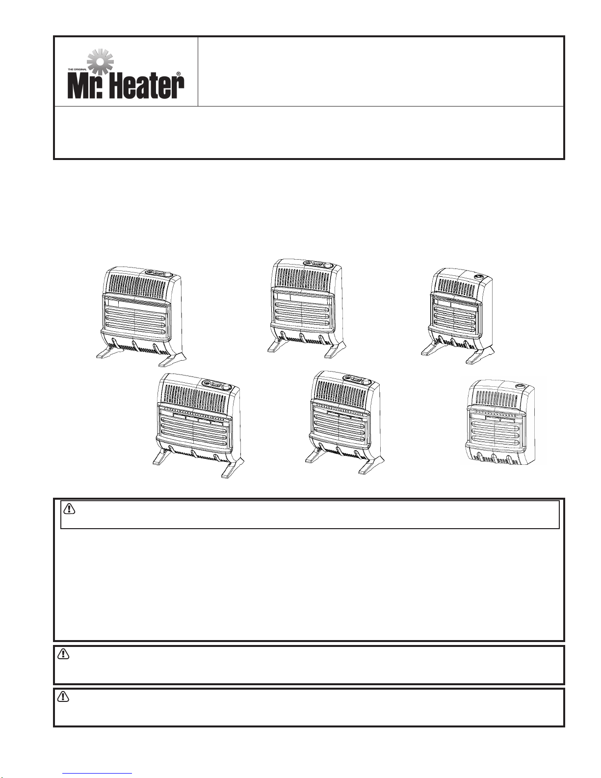
MHBF10LP
Mr. Heater MHBF10LP, HSBF10LP, MHBF30LPT, TSBF30LPT, MHBF20LPT Installation Instructions And Owner's Manual
...
INSTALLATION INSTRUCTIONS
AND OWNER’S MANUAL
READ INSTRUCTIONS CAREFULLY: Read and follow all instructions. Place instructions in a
safe place for future reference. Do not allow anyone who has not read these instructions to
assemble, light, adjust or operate the heater.
UNVENTED LP-GAS FIRED ROOM HEATER
Blue Flame Heaters Plaque Heaters
Model # Burn Rate Model # Burn Rate
MHBF10LP/TSBF10LP 10,000 Btu/hr MHIR10LP/TSIR10LP 10,000 Btu/hr
MHBF20LPT/TSBF20LPT 20,000 Btu/hr MHIR20LPT/TSIR20LPT 20,000 Btu/hr
MHBF30LPT/TSBF30LPT 30,000 Btu/hr MHIR30LPT/TSIR30LPT 30,000 Btu/hr
MHBF20LPT/
MHBF30LPT/
TSBF30LPT
MHIR30LPT/
TSIR30LPT
WARNING: If the information in this manual is not followed exactly, a fire or explosion may result causing
property damage, personal injury , or loss of life.
- Do not store or use gasoline or other flammable vapors and liquids in the vicinity of this or any other appliance.
- WHAT TO DO IF YOU SMELL GAS
TSBF20LPT
MHIR20LPT/
TSIR20LPT
MHBF10LP/
TSBF10LP
MHIR10LP/
TSIR10LP
• Do not try to light any appliance
• Do not touch an electrical switch; do not use any phone in your building.
• Immediately call your gas supplier from a neighbor’s phone. Follow the gas supplier’s instructions.
• If you cannot reach your gas supplier, call the fire dep artment.
- Installation and service must be performed by a qualified installer, service agency, or the gas supplier.
WARNING: This is an unvented gas-fired heater. It uses air (oxygen) from the room in which it is installed.
Provisions for adequate combustion and ventilation air must be provided. Refer to Fresh Air for Combustion and
V entilation section on page 3 of this manual.
WARNING: Improper installation, adjustment, alteration, service or maintenance can cause injury or property
damage. Refer to this manual for correct installation and operational procedures. For assistance or additional
information consult a qualified installer , service agency, or gas supplier.
ENERCO GROUP, INC., 4560 W. 160TH ST., CLEVELAND, OHIO 44135 · 216-916-3000
Installation instructions and Owner’s Manual
1
70575 Rev. C 08/05
This appliance may be installed in an aftermarket* permanently manufactured (mobile) home, where not prohibited by
local codes.This appliance is only for use with the type of gas indicated on the rating plate. This appliance is not
convertible for use with any other gas.
*Aftermarket completion of sale, not for the purpose of resale, from the manufacturer .
WARNINGS
IMPORTANT: Read this owner’s manual carefully
and completely before trying to assembly , operate,
or service this heater. Improper use of this heater
can cause serious injury or death from burns, fire,
explosion, electrical shock, and carbon monoxide
poisoning.
WARNING: Do not use any accessory not approved for use with this heater.
WARNING: Any change to this heater or its controls
can be dangerous.
• Do not place clothing or other flammable
material on or near the appliance. Never
place any objects on the heater.
• Due to high temperatures, heater should be
kept out of traffic and away from furniture and
draperies.
• Surface of heater becomes very hot when
running. Keep children and adults away from
hot surfaces to avoid burns or clothing ignition.
Heater will remain hot for a time after shutdown. Allow heater surfaces to cool before
handling.
• Y oung children should be carefully supervised
when they are in the same room with heater.
• Make sure grille guard is in place before
running heater. If screen or grille guard is
removed for servicing it must be replaced prior
to operating the heater.
• Keep the appliance area clear and free from
combustible materials, gasoline, and other
flammable vapors and liquids.
PRECAUTIONS:
1. MHBF-10 LP and MHIR-10LP may be installed in a
bedroom, but not a bathroom, or any place where a
strong wind would shut down the appliance.
2. MHBF-20 LPT, MHBF-30 LPT, MHIR-20 LPT and
MHIR-30 LPT may not be installed in a bedroom or
bathroom, or any place where a strong wind would
shut down the appliance.
3. This heater needs outside ventilation air to run
properly . The Oxygen Depletion Sensor (ODS)
safety shutoff system shuts down the heater if not
enough fresh air is available. See Fresh Air for
Combustion and Ventilation, page 3.
4. Keep all air openings in heater clear, free of debris or
any blockage. This will insure that enough air for
proper combustion enters the heater.
5. If heater shuts off, do not relight until you provide
fresh, outside air. If heater keeps shutting off, it
requires servicing.
6. Turn of f and unplug heater and let cool before
servicing. Only a qualified service person should
service and repair heater .
7. Do not run heater:
• Where flammable liquids or vapors are used or
stored
• During dusty conditions.
8. Before using furniture polish, wax, carpet cleaner or
similar products, turn heater off. If heated the vapors
from these products may create a white powder
residue within burner box or on adjacent walls or
furniture.
9. Do not use heater if any part has been underwater .
Immediately call a qualified service technician to
inspect the room heater and to replace any part of
the control system and any gas control which has
been underwater.
10.Operating heater above elevations of 4,500 feet
could cause pilot/ODS to shutdown heater .
1 1.Always run heater with control knob in a locked
position. Never set control knob between locked
positions. Poor combustion and higher levels of
carbon monoxide may result if control knob is left
between locked positions.
DANGER: Carbon monoxide poisoning may lead to
death.
Carbon Monoxide Poisoning:
Early signs of carbon monoxide poisoning resemble the
flu, with headaches, dizziness, or nausea. If you have
these signs, the heater may not be working properly .
Get fresh air at once! Have heater serviced. Some
people are more affected by carbon monoxide than
others. These include pregnant women, persons with
heart or lung disease or anemia, those under the
influence of alcohol, and those at high altitudes.
Propane/LP Gas:
Propoane/LP gas is odorless. An odor making agent is
added to propane/LP gas. The odor help s you detect a
Propane/LP gas leak. However the odor added to
propane/LP gas may be present even though no odor
exists. Make certain you read and understand all
warnings. Keep this manual for reference. It is your
guide to safe and proper operation of this heater.
2 Installation instructions and Owner’s Manual
70575 Rev. C 8/05
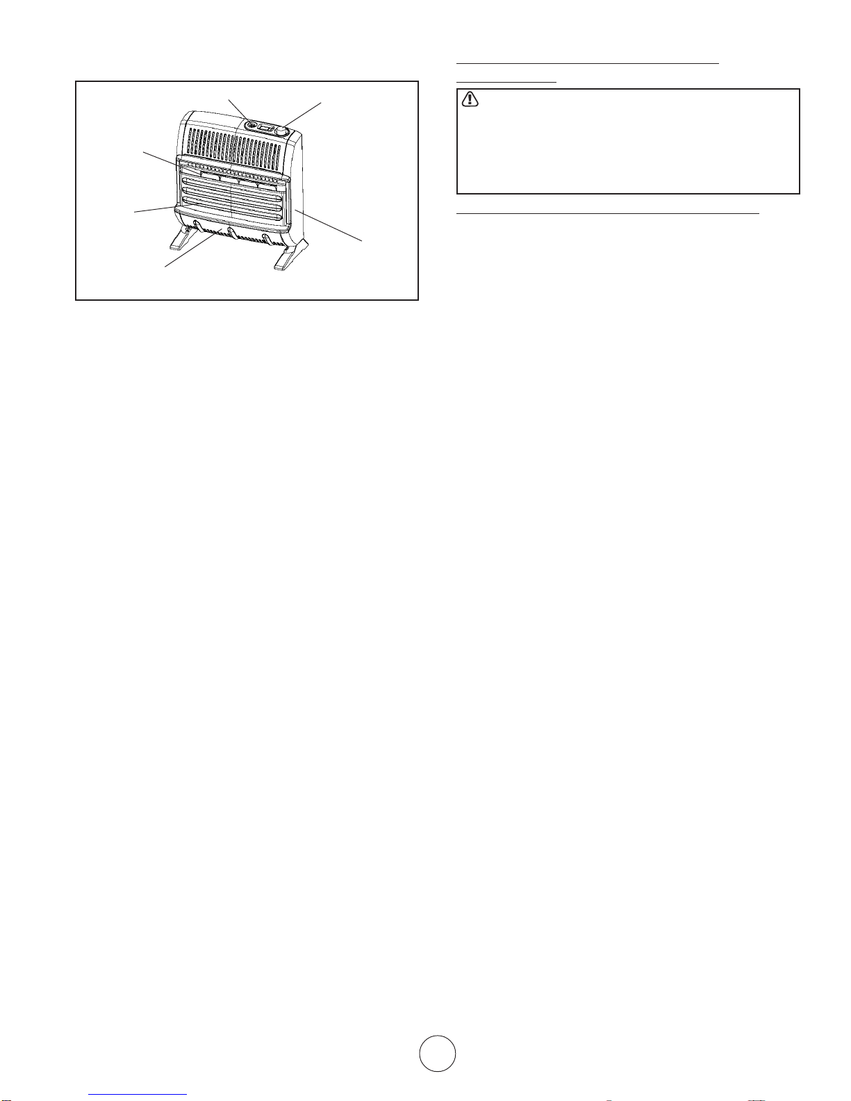
Product Features
Ignitor Button
Burners
Control Knob
FRESH AIR FOR COMBUSTION AND
VENTILATION
WARNING: This heater shall not be inst alled in a
confined space or unusually tight construction
unless provisions are provided for adequate combustion and ventilation air. Read the following
instructions to insure proper fresh air for this and
other fuel-burning appliances in your home.
Grill
Heater
Cabinet
Front Panel
Figure 1
SAFETY DEVICE
This heater has a pilot with an Oxygen Depletion Sensor
(ODS) safety shut off system. The ODS/pilot shuts of f
the heater if there is not enough fresh air.
IGNITION SYSTEM
PIEZO: BF10LP/ IR10LP – The heater is equipped with
a piezo manual ignitor. This system requires no
matches, batteries, or other source to light heater.
Electronic: BF20LPT/BF30LPT/IR20LPT/IR30LPT –
The heater is equipped with an electronic manual
ignitor. This system requires no matches, or other
source to light heater, but does require one AA battery to
operate ignitor.
To install or replace battery unscrew the ignitor
cap (red button), insert battery and replace cap.
THERMOST ATIC CONTROL ON
THERMOST AT MODELS
(BF20LPT, BF30LPT, IR20LPT and IR30LPT)
These heaters have a control valve with a thermostat
sensing bulb. This results in the greatest heater comfort
and may result in lower bills.
LOCAL CODES
Install and use heater with care.
Installation must conform to local codes or in the
absences of local codes, use the latest edition of
National Fuel Gas Code ANSI Z223.1/NFPA 54.
UNPACKING
1. Remove heater from carton.
2. Remove all protective packaging applied to
heater for shipment.
3. Check heater for any shipping damage. If
heater is damaged, promptly inform dealer
where you bought heater.
ESTABLISHING ADEQUATE VENTILATION
The following are excerpts from National Fuel Gas
Code, NFP A 54/ ANSI Z223.1, Section 5.3, Air for
Combustion and Ventilation. All sp aces in homes fall
into one of the three following ventilation classifications:
1. Unusually Tight Construction
2. Unconfined Space
3. Confined Space
This heater must not be installed in a confined space or
unusually tight construction unless provisions are
provided for adequate combustion and ventilation air.
The information on pages 3 through 5 will help you
classify your space and provide adequate ventilation.
Unusually Tight Construction
If your home meets all of the three following criteria you
must provide additional fresh air. See V entilation Air
from Outdoors, page 5.
Unusually tight construction is defined as construction
where:
a. Walls and ceilings exposed to the outside atmo-
sphere have a continuous water vapor retarder with a
rating of one perm (6 x 10
-11
kg per pa-sec-m2) or less
with openings gasketed or sealed and
b. Whether stripping has been added on openable
windows and doors, and
c. Caulking or sealants are applied to areas such as
joints around windows and door frames, between
wall-ceiling joints, between wall panels, at penetrations for plumbing, electrical, and gas lines, and at
other openings.
If you home does not meet all of the three criteria
above, see Determing the T ype of Heater Location
Space, page 4.
Confined Space and Unconfined Space
The National Fuel Gas Code, NFP A 54/ ANSI Z223.1
defines a confined space as a space whose volume is
less than 50 cubic feet per 1,000 Btu per hour (4.8 m
per kW) of the aggregate input rating of all appliances
installed in that space, and an unconfined space as a
space whose volume is not less than 50 cubic feet per
1,000 Btu per hour (4.8 m3 per kW) of the aggregate
input rating of all appliances installed in that space.
Rooms communicating directly with the space in which
the appliances are installed*, through openings not
furnished with doors, are considered a part of the
unconfined space.
3
Installation instructions and Owner’s Manual
3
*Adjoining rooms are communication only if there
are doorless passageways or ventilation grills
between them.
DETERMINING THE TYPE OF HEA TER
LOCATION SPACE:
Use this method to determine if you have a confined or
unconfined space.
Note: the space includes the room in which you
install heater plus any adjoining rooms with doorless
passageways or ventilation grills between the
rooms.
1. Find the volume of the space by multiplying room
length x width x height.
Example: Space size 18f t (length) x 18ft. (width) x 8ft.
(height) = 2592
If additional ventilation to adjoining room is supplied with
grills or openings, add the volume of these rooms to the
total volume of the space.
2. Divide the space volume by 50 cubic feet to determine the maximum Btu/hr the space can support.
Example: 2592 cu.ft. (volume of space) / 50 cu.ft. = 51.8
or 51,800 (maximum Btu/hr the space can
support)
WARNING: If the area in which the heater may be
operated in smaller that that defined as an unconfined space or if the building is of unusually tight
construction, provide adequate combustion and
ventilation air by on the methods described in the
National Fuel Gas Code, NFP A 54/ ANSI Z223.1,
Section 5.3 or applicable local codes.
3. Add the Btu/hr of all the fuel-burning appliances in
the space such as, V ent–free heater, Gas water
heater, Gas furnace, Vented gas heater, Gas fireplace logs, and Other gas appliances*
*Do not include direct-vent gas appliances. Directvent draws combustion air from the outdoors and
vents to the outdoors.
Example:
Gas water heater 40,000 Btu/hr
Vent Free Heater + 20,000 Btu/hr
T otal =60,000 Btu/hr
4. Compare the maximum Btu/hr the space can support
with the actual amount of Btu/hr used.
Example: 51,800 Btu/hr (maximum Btu/hr the
space can support)
60,000 Btu/hr (Actual amount of Btu/hr
used)
The space in the above example is a confined
space because the actual Btu/hr used is more than
the maximum Btu/hr the space can support.
Y ou must provide additional fresh air. Your options
are as follows:
A. Rework worksheet, and the space of an adjoining
room. If the extra space provides an unconfined
space, remove door to adjoining room or add ventilation grills between the rooms. See Ventilation Air
From Inside Building (Fig. 2)
B. V ent room directly to the outdoors. See Ventilation
Air From Outdoors (Fig. 3).
C.Inst all a lower Btu/hr heater if lower Btu/hr size
makes room unconfined.
If actual Btu/hr used is less than the maximum Btu/
hr the space can support, the space is an unconfined space. You will need no additional fresh air
ventilation.
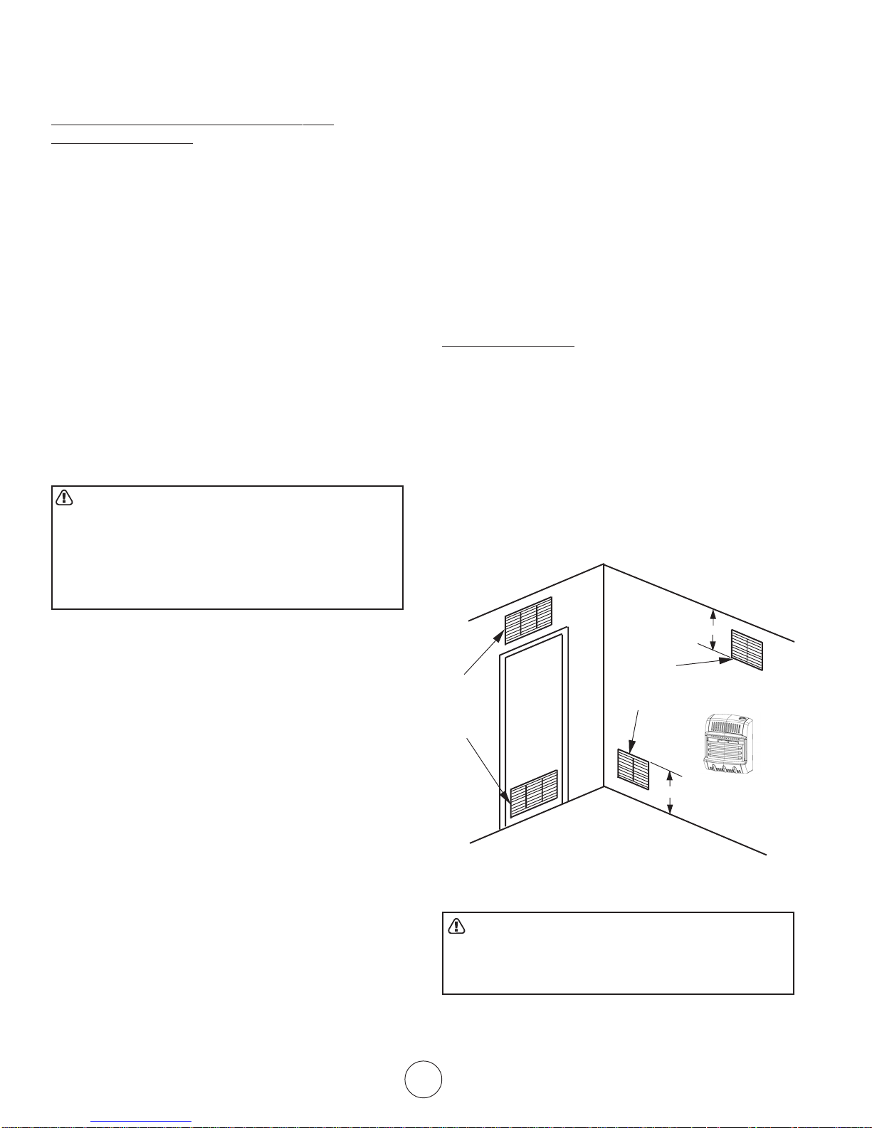
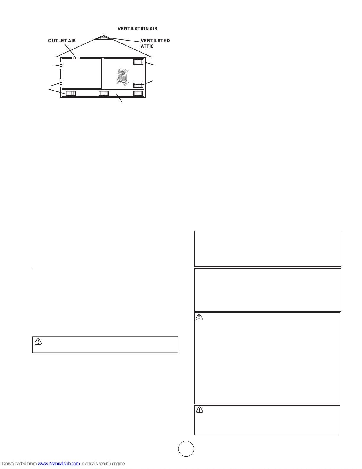
VENTILATION AIR
Ventilation from Inside Building
This fresh air would come from an adjoining unconfined
space. When ventilation to an adjoining unconfined
space, you must provide two permanent openings: one
within 12” of the ceiling and one within 12” of the floor
on the wall connecting the two spaces (see options 1 &
2 of fig. 2). You can also remove door into adjoining
room (see option3, fig 2). Follow the National Fuel Gas
Code NFP A 54/ ANSI Z223.1, Section 5.3, Air for
Combustion and Ventilation for required size of ventilation grills or ducts.
12”
Ventilation
Gills into
Adjoining
Room Option 1
Or remove
door into
Adjoining
Room Option 3
Ventilation Gills into
Adjoining Room Option 2
12”
Figure 2
WARNING: Rework worksheet, adding the space of
the adjoining unconfined space. The combined
space must have enough fresh air to supply all
appliance in both spaces.
4 Installation instructions and Owner’s Manual
70575 Rev. C 8/05
OUTLET
5
6
6
12345
1
5
12345
12345
1
5
12345
AIR
INLET
AIR
OUTLET AIR
234
VENTILA TION AIR
VENTILATED
ATTIC
234
234
2345
VENTILA TION CRA WL SPACE
2345
TO ATTIC
TO CRAWL
SPACE
• Ground joint union
• Test gauge connection*
• Sediment trap
• Tee joint
• Pipe wrench
*A CSA/AGA certified equipment shutoff valve with 1/8”
NPT tap is an acceptable alternative to test gauge
connection. Purchase a CSA/AGA certified equipment
shutoff valve from your dealer . See Accessories, page
17.
Figure 3.
Ventilation from Outdoors
If necessary provide extra fresh air by using ventilation
grills or ducts. Connect these items directly to the
outdoors or spaces open to the outdoors. These
include attics* and crawl spaces. Follow the National
Fuel Gas Code NFP A 54/ ANSI Z223.1, Section 5.3, Air
for Combustion and Ventilation for required size of
ventilation grills or ducts.
*IMPORTANT: Do not provide openings for inlet or
outlet into attic. If attic has a thermostat-controlled
power vent, heated air entering the attic will activate
the power vent.
IMPORTANT: Vent-free heaters add moisture to the
air. Although this is beneficial, installing heater in
rooms without enough ventilation air may cause
mildew to form from too much moisture. See Fresh
Air for Combustion and Ventilation, p ages 3 through
5.
INSTALLATION
NOTICE: This heater is intended for the use as supple-
mental heat. Use this heater along with your primary
heating system. Do not install this heater as your
primary heat source. If you have a central heating
system, you may run system’s circulating blower while
using heater. This will help circulate the heat throughout
the house. In the event of a power outage, you can use
this heater as your primary heat source for the duration
of the outage.
WARNING: A qualified service person must install
heater. Follow all local codes.
CHECK GAS TYPE
Use only LP-gas. If your gas supply is not LP-gas, do
not install heater . Call dealer where you bought heater
for proper type heater.
THIS INST ALLA TION REQUIRES:
Before installing heater , make sure you have the items
listed below:
• Piping (check local codes)
• Sealant (resistant to LP_Gas)
• Equipment shutoff valve*
LOCA TING HEATER
This heater is designed to be mounted on the wall. The
heater can also be located on a non-combustible floor,
away from a wall by using the floor mounting stands
included with the heater. If installed on combustible
flooring such as carpeting, tile or other combustible
material other than wood flooring, the heater must be
placed on a wood panel the full width and depth of the
appliance.
For convenience and efficiency , install the heater:
• Where there is easy access for operation,
inspection, and service.
• In the coldest part of the room.
• If planning to use fan, locate heater near an
electrical outlet.
CAUTION: If you install the heater in a home garage:
• Heater pilot and burner must be at least 18
inches above floor.
• Locate heater where moving vehicle will not hit it.
CAUTION: This heater creates warm air currents. These
currents move heat to wall surfaces next to heater. Installing heater next to vinyl or cloth wall covering or operating heater where impurities (such as tobacco smoke,
aromatic candles, cleaning fluids, oil or kerosene lamps,
etc.) are present in the air may discolor walls.
WARNING: Never install the heater:
• In a bathroom.
• In a bedroom (IR20LPT, IR30LPT , BF20LPT or
BF30LPT)
• In a recreational vehicle.
• Where curtains, furniture, clothing, or other
flammable objects are less than 36 inches from
the front, top, or sides of the heater.
• As a fireplace insert
• In high-traf fic areas
• In windy or draf ty areas
WARNING: Heater must be mounted to maintain the
minimum clearances shown in Figure 4. If possible,
provide greater clearances from the floor, ceiling,
and joining walls.
Installation instructions and Owner’s Manual
5
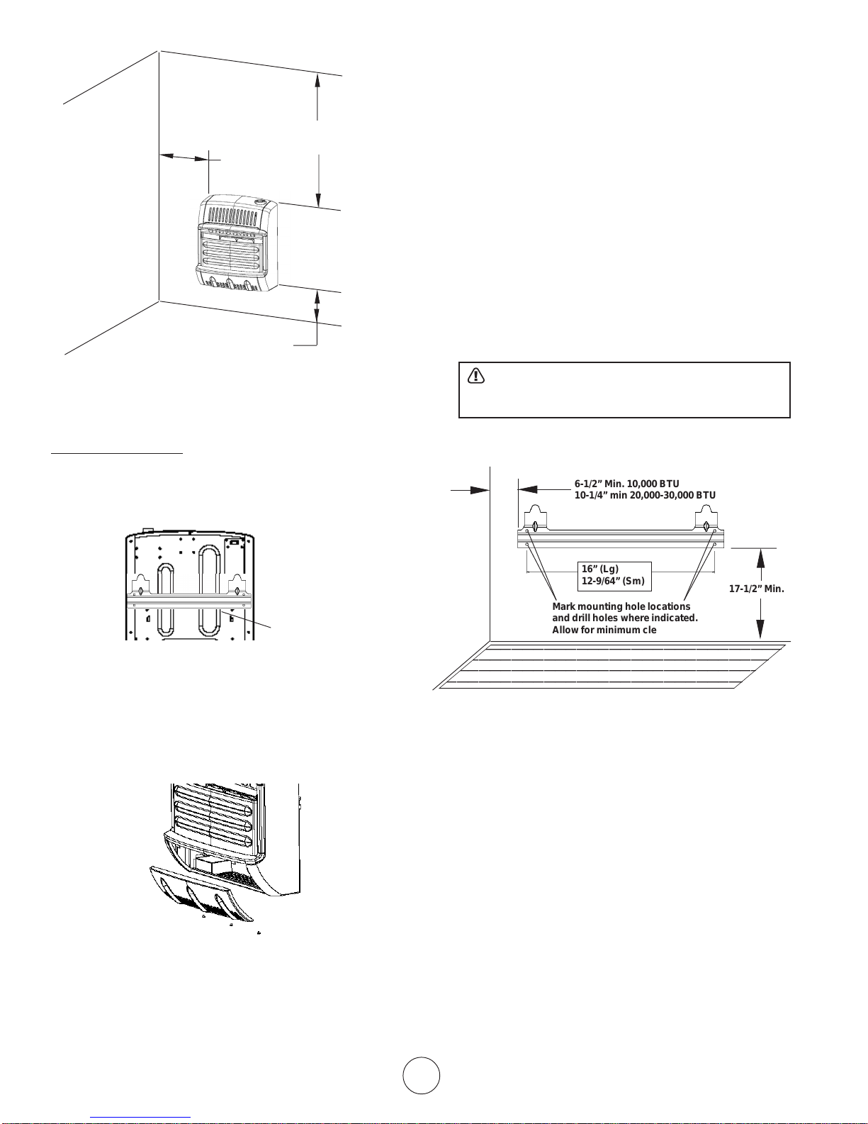
36” min.
6” Min from
adjoining
walls
Left
Side
Floor
2” min. to top surface of carpet,
tile or other combustible material
from ceiling
Right
Side
Figure 4
FASTENING HEATER TO WALL
Mounting Bracket
The mounting bracket in located on the back panel of
heater (see figure 5). It has been taped there for shipping. Remove mounting bracket from back panel.
1. Attach to wall studs
2. Attach to wall anchor
Attaching to Wall Stud:
This way is the best providing the strongest mounting in
wood frame houses.
Attaching to Wall Anchor:
This way allows you to attach mounting bracket to
hollow walls (wall areas between studs) or to solid walls
(concrete or masonry).
Decide which way best suits your needs. Either method
will provide a secure hold for the mounting bracket.
1. Tape mounting bracket to wall where heater will
be located. Make sure mounting bracket is
level. For wall stud mounting locate one end of
the mounting bracket over a wall stud.
WARNING: Maintain minimum clearances
shown in figure 7. If you can, provide greater
clearances from the floor and joining wall.
2. Mark screw locations on wall (see figure 7).
3. Remove tape and mount bracket from wall.
6-1/2” Min. 10,000 BTU
10-1/4” min 20,000-30,000 BTU
Mounting
Bracket
Figure 5
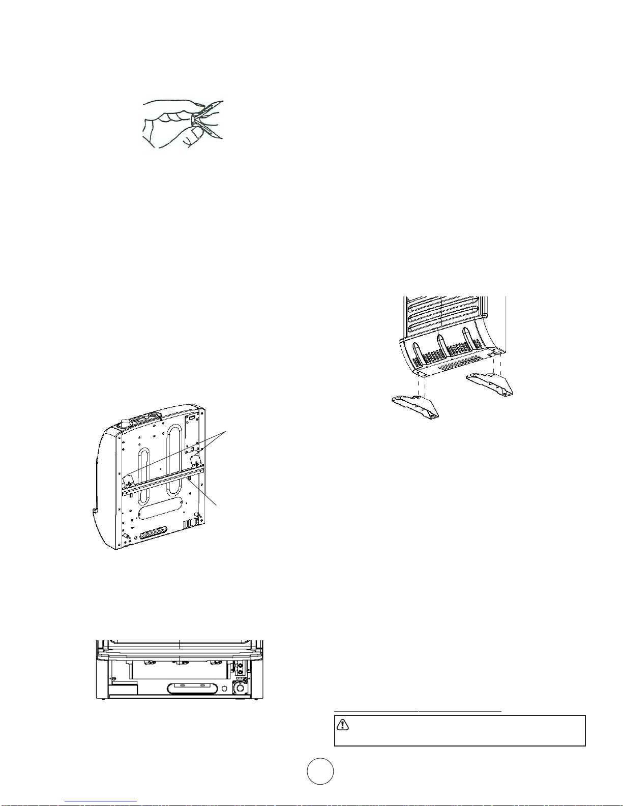
Removing Front Panel of Heater
1. Remove three screws on bottom front of front
panel.
2. Pull bottom of front panel forward, then down
(see figure 6)
Figure 6
Attaching Mounting Bracket to Wall
Use holes on each end of mounting bracket to attach
bracket to wall. These holes are 16 inches apart.
Attach mounting bracket to wall in one of two following
ways.
16” (Lg)
12-9/64” (Sm)
Adjoining Wall
Mark mounting hole locations
and drill holes where indicated.
Allow for minimum clearances
Figure 7
Attaching to Wall Stud:
For attaching mounting bracket to wall studs
1. Drill holes at marked locations using 9/64” drill
bit.
2. Place mounting bracket onto wall. Line up holes
on each end of bracket with hole drilled in wall.
3. Insert mounting screws through bracket and
into wall studs.
4. Tighten screws until mounting bracket is firmly
fastened to wall studs.
Attaching to Wall using Anchor:
For attaching mounting bracket to hollow walls (wall
areas between studs) or solid walls (concrete or masonry)
Note: Wall anchors, mounting screws, and spacer
are in hardware package. The hardware package is
provided with heater.
6 Installation instructions and Owner’s Manual
70575 Rev. C 8/05
17-1/2” Min.
1. Drill holes at marked locations using 5/16” drill
bit. For solid walls (concrete or masonry), drill
at least 1” deep.
2. Fold wall anchor as shown in figure 8 below.
Figure 8.
3. Insert wall anchor (wings first) into hole. Tap
anchor flush to wall.
4. For thin walls (1/2” or less) insert red key into
wall anchor.
5. Place mounting bracket onto wall. Line up holes
on each end of bracket with wall anchors.
6. Insert mounting screws through bracket and
into wall anchors.
7. Tighten screws until mounting bracket is firmly
fastened to wall.
Placing Heater on Mounting Bracket
1. Locate two horizontal slots on back pane of
heater (see figure 19).
2. Place heater onto mounting bracket. Slide
horizontal slots onto stand-out tabs on mounting
bracket.
4. If installing bottom mounting screw into hollow
or solid wall, install wall anchors. Follow steps 1
through 4 under Att aching to Wall using Anchor .
If installing bottom mounting screw into wall
stud, drill holes at marked locations using 9/64”
drill bit.
5. Re-place heater onto mounting bracket.
6. Place spacers between bottom mounting holes
and wall anchor or drilled hole.
7. Hold spacer in place with one hand. With the
other hand, insert mounting screw through
bottom mounting hole and spacer . Place tip of
screw in opening of wall anchor or drilled hole.
8. Tighten both screws until heater is firmly
secured to wall. Do not over tighten.
Note: Do not re-place front panel at this time. Replace front panel after making gas connections and
checking for leaks.
FLOOR MOUNTING AWAY FROM W ALL:
Horizontal Slots
Mounting Bracket
mounted to wall
Figure 9
Installing Bottom Mounting Screws
1. Locate two bottom mounting holes. These
holes are near bottom on back panel of heater
(see figure 10).
Figure 10
2. Mark screws locations on wall.
3. Remove heater from mounting bracket.
Figure 11
Installing Support Feet (see figure 11)
1. Lay heater onto table on its back with bottom
edge overhanging table edge.
2. Securely attach feet to bottom of heater using 2
– self-tapping screws each.
Note: Feet should have long end going out the front
of heater, and the edge coinciding with side of
heater. If feet overhang side of the heater, switch
leg location.
3. Place heater on non-combustible surface (see
Locating Heater above) before proceeding with
gas connection. If this will be a permanent
location, heater may be locked into position
using anchoring holes in mounting feet.
Note: Use of floor mounting feet will require you to
use a 3/8 NPT street elbow to make gas connection.
CONNECTING TO GAS SUPPLY
WARNING: A qualified service person must connect
heater to gas supply . Follow all local codes.
Installation instructions and Owner’s Manual
7
WARNING: This appliance requires a 3/8” NPT
(National Pipe Thread) inlet connection to the
pressure regulator. Use of floor mounting feet will
require you to use a 3/8 NPT street elbow to make
gas connection.
CAUTION: Never connect heater directly to the Propane
supply. This heater requires an external regulator (not
supplied). Install the external regulator between the heater
and Propane/LP supply .
The installer must supply an external regulator . The
external regulator will reduce the incoming gas pressure
to between 1 1 and 14 inches of water. If you do not
reduce incoming gas pressure heater regulator damage
could occur. Inst all external regulator with the vent
pointing down as shown in Figure 12. Pointing the vent
down protects it from freezing rain or sleet.
CAUTION: Use only new black iron or steel pipe.
Internally-tinned copper tubing may be used in certain
areas. Check your local codes. Use pipe of larger
enough diameter to allow proper gas volume to heater.
If pipe is too small, undue loss of pressure will occur.
Installation must include an equipment shutoff valve,
union and plugged 1/8” NPT tap. Locate NPT tap within
reach of test gauge hookup. NPT tap must be upstream
from heater (see figure 12).
Pressure
Regulator
3/8” NPT Pipe Nipple
Ground Joint Union
Equipment
Shutoff Valve
From Gas Meter
(4” W.C. to 10.5”
W.C. Pressure)
Tee Joint
Tee Joint
Pipe Nipple
Cap
3” Minimum
Heater
Cabinet
Test Gauge
Connection
Reducer Bushing
to 1/8” NPT
1/8” NPT Plug Tap
Sediment
Trap
Figure 12
*A CSA/AGA certified equipment shutoff valve with 1/8”
NPT tap is an acceptable alternative to test gauge
connection. Purchase the CSA/AGA certified equipment shutoff valve from your dealer . See Accessories,
page 17.
IMPORTANT: Install an equipment shutof f valve in an
accessible location. The equipment shutoff valve is for
turning on or shutting off the gas to the appliance.
Apply pipe joint sealant lightly to male threads. This will
prevent excess sealant from going into pipe. Excess
sealant in pipe could result in clogged heater fuel train.
CAUTION: Use pipe joint sealant that is resistant to
LP-Gas.
Install sediment trap in supply line as shown in figure
12. Locate sediment trap where it is within reach for
cleaning. A sediment trap traps moisture and contaminants. This keeps them from going into heater. If
sediment trap is not installed or is installed improperly,
heater may not run correctly .
IMPORTANT: Hold pressure regulator with wrench
when connecting it to gas piping and/or fittings.
CHECKING GAS CONNECTIONS
WARNING: Test all gas piping and connections for
leaks after installing or servicing. Correct all leaks
at once.
WARNING: Never use an open flame to check for a
gas leak. Apply a mixture of liquid soap and water to
all joints. Bubbles forming show a leak. Correct all
leaks at once.
PRESSURE TESTING GAS SUPPLY PIPING
SYSTEM
Test pressure in Excess of ½ psig (3.5kPa)
1. Disconnect appliance with its appliance main
gas valve (control valve) and equipment shutoff
valve from gas supply piping system. Pressures in excess of ½ psig will damage heater
regulator .
2. Cap off open end of gas pipe where equipment
shutoff valve was connected.
3. Pressurize supply piping system by either using
compressed air or opening main gas valve on
or near gas meter.
4. Check all connections and joints in gas supply
piping system. Apply mixture of liquid soap and
water to gas joints. Bubbles forming show a
leak.
5. Correct all leaks at once.
6. Depressurize and relieve pressure in supply
piping system.
7. Reconnect heater and equipment shutoff valve
to gas supply .
8. Reconnected fittings must be checked for leaks
in next section.
Test Pressure Equal To or Less Than ½ psig (3.5 kPa)
1. Close equipment shutoff valve (see figure 13).
2. Pressurize supply piping system by either using
compressed air or opening propne/LP supply
valve.
3. Check all joints from the propane/LP supply
valve to equipment shutoff valve (see figure 14).
Apply mixture of liquid soap and water to gas
joints. Bubbles forming show a leak.
4. Correct all leaks at once.
5. Depressurize and relieve pressure from supply
piping system.
8 Installation instructions and Owner’s Manual
70575 Rev. C 8/05
 Loading...