

Page 1
Installer: Leave this manual with the appliance. Consumer: Retain this manual for future reference.
OPERATING INSTRUCTIONS AND OWNER’S MANUAL
MR. HEATER
MODEL
MH25NG
MH25LP
GAS FIRED INFRA-RED WORKSHOP HEATER
READ INSTRUCTIONS CAREFULLY: Read and
follow all instructions. Place instructions in a
safe place for future reference. Do not allow
anyone who has not read these instructions to
assemble, light, adjust or operate the heater.
HEATSTAR
MODEL
HS25NG
HS25LP
WARNING: If the information in this manual is not followed exactly, a fire or explosion may result causing
property damage, personal injury, or loss of life.
- Do not store or use gasoline or other flammable vapors and liquids in the vicinity of this or any other appliance.
- WHAT TO DO IF YOU SMELL GAS
• Shut off gas supply
• Do not try to light any appliance
• Do not touch an electrical switch; do not use any phone in your building.
• Immediately call your gas supplier from a neighbor’s phone. Follow the gas supplier’s instructions.
• If you cannot reach your gas supplier, call the fire department.
- Installation and service must be performed by a qualified installer, service agency, or the gas supplier.
WARNING: This is an unvented gas-fired heater. It uses air (oxygen) from the room in which it is installed.
Provisions for adequate combustion and ventilation air must be provided. Refer to Fresh Air for Combustion and
Ventilation section on page 3 of this manual.
WARNING: Improper installation, adjustment, alteration, service or maintenance can cause property damage,
injury or death. Read the installation, operation, and maintenance instructions thoroughly before installing or
servicing this equipment. For assistance or additional information consult a qualified installer, service agency, or
gas supplier.
ENERCO GROUP, INC., 4560 W. 160TH ST., CLEVELAND, OHIO 44135 · 216-916-3000
18673 Rev. D 06/06
Page 2
WARNINGS
WARNING: Improper installation, adjustment,
alteration, service or maintenance can cause
property damage, injury or death. Read the
installation, operation, and maintenance instructions thoroughly before installing or servicing this
equipment. For assistance or additional information consult a qualified installer, service agency, or
gas supplier.
WARNING: When used without fresh air, heater
may give off CARBON MONOXIDE, an odorless
poisonous gas. OPEN WINDOW AN INCH OR
TWO FOR FRESH AIR WHEN USING HEATER.
WARNING: This heater is equipped with a PILOT
LIGHT SAFETY SYSTEM. DO NOT TAMPER
WITH PILOT LIGHT SAFETY SYSTEM.
DANGER: Carbon monoxide poisoning may lead to
death.
Carbon Monoxide Poisoning:
Early signs of carbon monoxide poisoning resemble the
flu, with headaches, dizziness, or nausea. If you have
these signs, the heater may not be working properly. Get
fresh air at once! Have heater serviced. Some people are
more affected by carbon monoxide than others. These
include pregnant women, persons with heart or lung
disease or anemia, those under the influence of alcohol,
and those at high altitudes.
CAUTION
• Never connect gas valve or thermostat to line voltage
or a transformer.
• If the infra-red color of the grid becomes dull when the
building furnace is operating, consult gas supplier on
correct gas supply piping sizes.
• This heater is for indoor installation only!
WARNING: If heater shuts off, do not relight until
you provide fresh air. If heater keeps shutting off,
have it serviced. Keep burner and control clean.
Open door for 5 minutes.
Maintain clearances as shown in Figure 2 or on
heater nameplate.
• DO NOT USE MATCH OR OTHER FLAME
FOR LEAK TESTING.
• DO NOT EXCEED 1/2 PSI INLET PRESSURE
TO HEATER.
NOTE
Gasket binder material used in this heater assembly will
temporarily emit an odor and/or vapor. This condition will
clear up in approximately 20 minutes and thereafter will
not reoccur. Refer to Chapter 2 for ventilation.
TABLE OF CONTENTS
Chapter Title Page
I Introduction ............................................ 3
II Heater Installation .................................. 5
III Heater Operating Instructions ................. 10
IV Operator Maintenance Instructions ......... 12
V Replacement Parts List.......................... 15
Model # MH25NG/LP HS25NG/LP
Installation instructions and Owner’s Manual
2
Page 3
CHAPTER I
INTRODUCTION
1. EQUIPMENT
This heater is the consumer version of a highly successful, thoroughly tested, gas fired, infrared, industrial utility
heater.
This heater does not require an external electrical source
for operation.
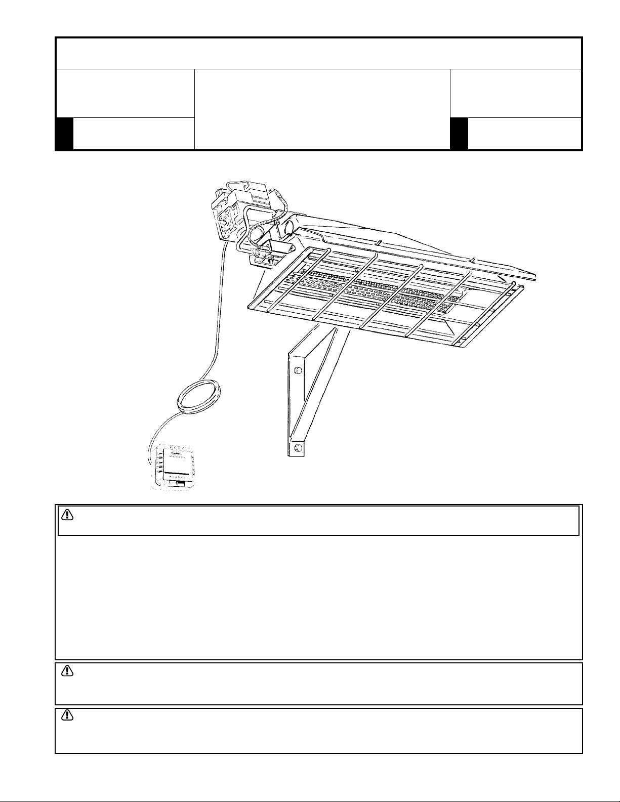
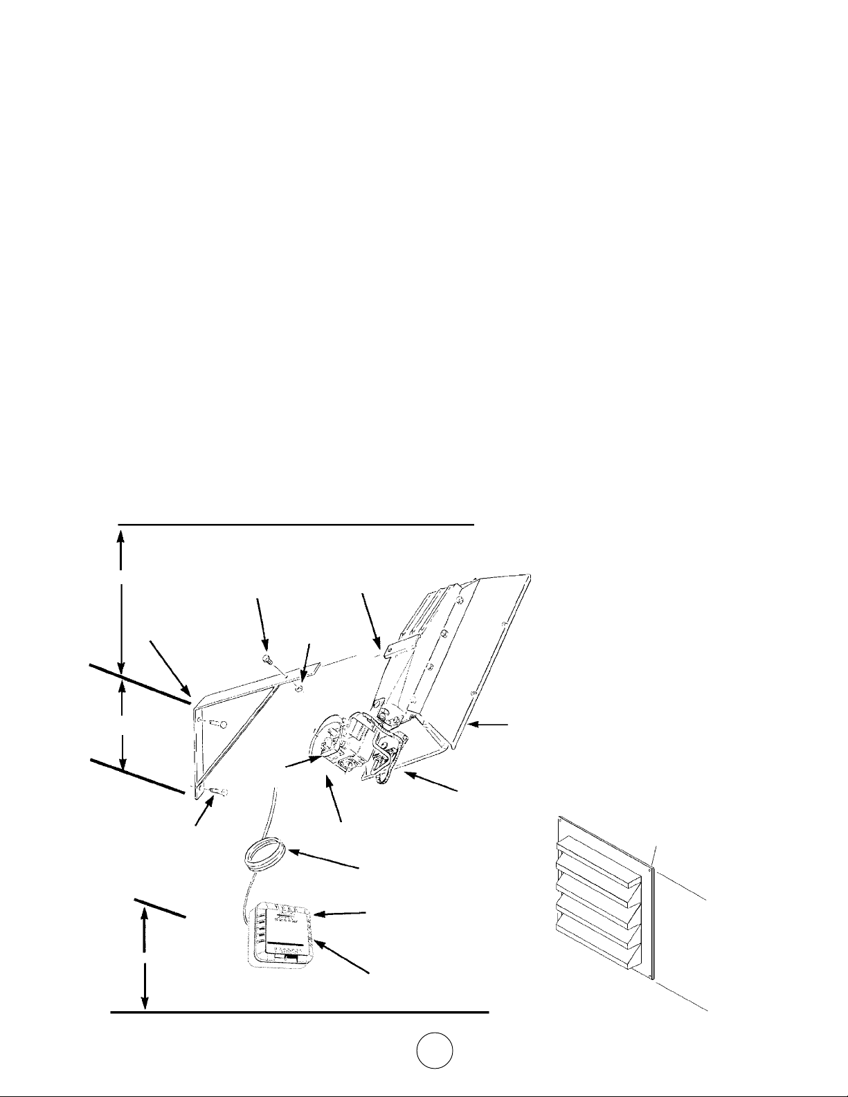
The major components of the heater and a typical
installation are identified in Figure 1. The basic heater
GAS CONTROL
VALVE
POWERPILE
GENERATOR
consists of the complete burner assembly, flue deflector,
grid, reflector assembly and face guard.
2. PURPOSE OF EQUIPMENT
WARNINGS
This heater is for indoor installation only.
This heater is designed to heat indoor areas. Do not
use for inhabited or small, enclosed areas.
This heater is an ideal selection when a simple and
easily installed method of heating a utility building is
required.
EXHAUST
VENT
THERMOSTAT
CABLE
THERMOSTAT
Figure 1. Heater Major Components
3. MODELS COVERED IN THIS MANUAL
Model MH25NG/HS25NG is for use where natural gas is
intended fuel source. Model MH25LP/HS25LP is for use
where propane gas is the intended fuel source.
4. MANUAL USE
• The procedures and information contained within
this manual will allow purchaser of this heater to
install and maintain the heater safely and
efficiently.
BASIC HEATER
WALL MOUNTING
BRACKET
• The cover and the following page provide a safety
summary that attempts to gather all the warnings used within the manual in one location.
• A table of contents is provided for easy reference
to any portion of the manual.
• Chapter 1 provides general information on the
use of this manual and on the heater.
Model # MH25NG/LP HS25NG/LP
Installation instructions and Owner’s Manual
3
Page 4
• Chapter 2 provides heater installation requirements
and information, such as: a) minimum distances
from heater components to combustible materials,
b) heater mounting requirements, c) venting
requirements, d) fuel supply requirements, e)
thermostat mounting.
• Chapter 3 covers startup, operation, and shutdown
of the heater.
• Chapter 4 provides operator maintenance instruc-
tions such as: troubleshooting, adjustments,
powerpile replacement and operator checks.
• Chapter 5 provides warranty and replacement
parts information.
5. GENERAL INFORMATION
• Your heater comes fully assembled and is tested
at the factory with the appropriate type of gas and
at the input pressures stated on the nameplate.
• Upon receipt and prior to attempting installation,
be sure to inspect the heater and its packaging for
damage and/or missing components. If damage is
found or missing components are suspected,
contact your dealer. See Chapter 5 for a complete
listing of items required for the safe and efficient
installation and use of this heater.
• Never attempt to operate the heater using a fuel
other than that specifically identified on the
nameplate.
• The installation of the heater must conform with all
local building codes or, in absence of governing
local codes, with the National Fuel Gas Code,
ANSI Z223.1 (NFPA 54). This code can be obtained from either the: Canadian Standards
Association, 8501 East Pleasant Valley Road,
Cleveland, OH 44131; or, NFPA, Battery March
Park, Quincy, MA 02269.
• Canadian installations must comply with CAN/
CGA-B149.1.2 gas code which can be purchased
from Canadian Gas Association, 55 Scarsdale
Road, Don Mills, Ontario M3B 2R3.
• Contact factory when appliance is to be installed at
high altitudes. Factory supply high altitude conversion kit with instructions and data plate.
• A plugged 1/8" N.P.T. Test Gage Connection is
provided on the heater gas control.
• See Tables 1 and 2 for heater specifications:
WARNING: Improper installation, adjustment, alteration,
service or maintenance can cause property damage,
injury or death. Read the installation, operation, and
maintenance instructions thoroughly before installing or
servicing this equipment. For assistance or additional
information consult a qualified installer, service agency,
or gas supplier.
• For additional information contact:
The factory.
• The following extra NFPA Manuals are helpful when
installing this heater in a location not anticipated in
this manual:
Number Related Subject
NFPA 88 Clearances to Combustible Surfaces
NFPA 409 Clearances to Combustible Surfaces
DO NOT EXCEED 1/2 PSI INLET PRESSURE TO HEATER
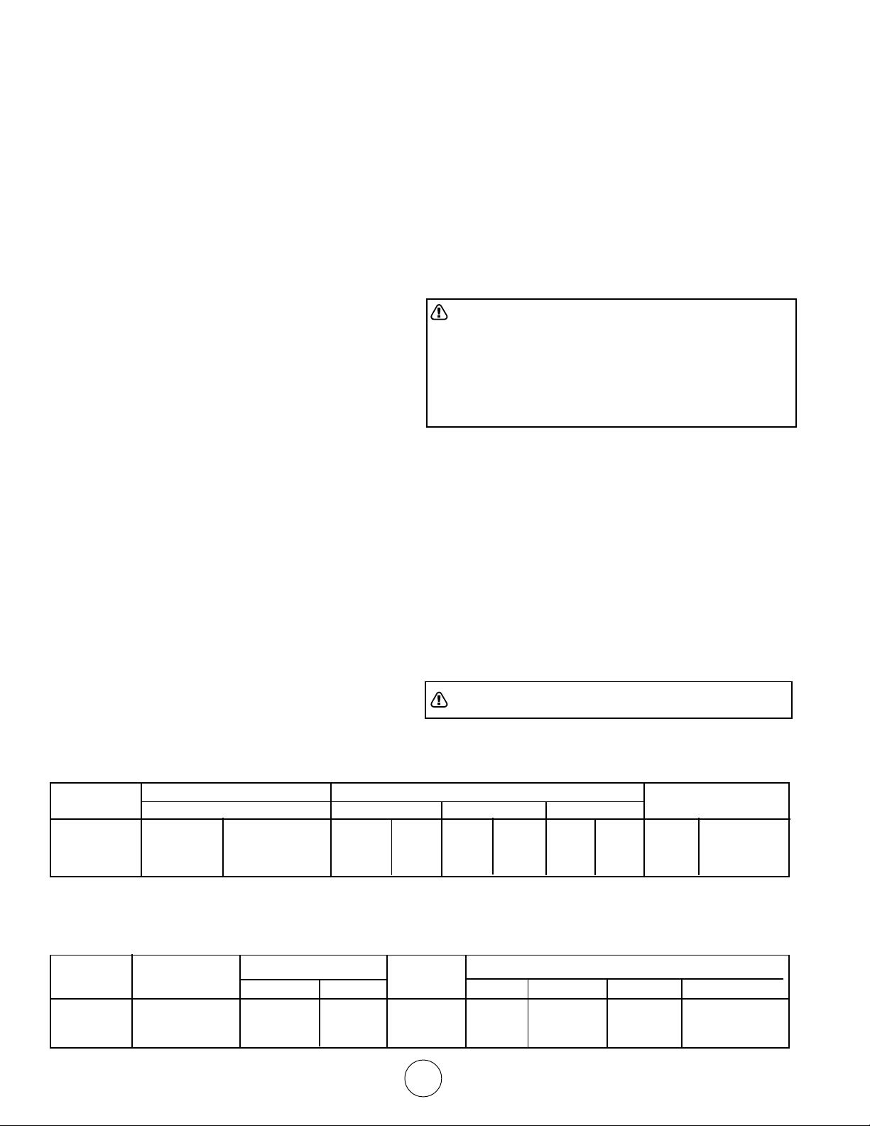
Table 1. BTU Ratings and Supply Pressures
MODEL BTU/HR. RATING GAS SUPPLY PRESSURE (W.C.) ORIFICE
NO. GAS MIN. MAX. MANIFOLD SIZE
NATURAL PROPANE NAT. L.P. NAT. L.P. NAT. L.P. NAT. L.P.
MH/HS25NG 25,000 — 7.0" — 14" — 6" — 45 —
MH/HS25LP — 22,000 — 11" — 14" — 10" — 55
Table 2. Heater Dimensions and Orifice Sizes
MODEL OPERATING ORIFICE SIZE INPUT SIZE
NO. PRESSURE BURNER PILOT BTU/H WIDTH LENGTH HEIGHT WEIGHT
MH/HS25NG 6.0"w.c. 45 .018 25.000 12-1/4" 29-3/4" 7" 20 lb.
MH/HS25LP 10"w.c. 55 .011 22,000 12-1/4" 29-3/4" 7" 20 lb.
Model # MH25NG/LP HS25NG/LP
Installation instructions and Owner’s Manual
4
Page 5
Provide adequate clearance to combustibles per Table 3 at
control end of heater for servicing and minimum on top and
sides for ventilation and combustion air supply.
A minimum clearance of 8’ above floor for public garages in
accordance with NFPA No. 88 most recent edition, or
Figure 1; whichever is larger.
Canadian installations in public garages must comply with
CGA 149B.1.9 most recent edition.
WARNING: Maintain clearances as shown in Figure 2
or on heater nameplate.
CHAPTER II
HEATER INSTALLATION
1. GENERAL INSTALLATION INFORMATION
AND REQUIREMENTS
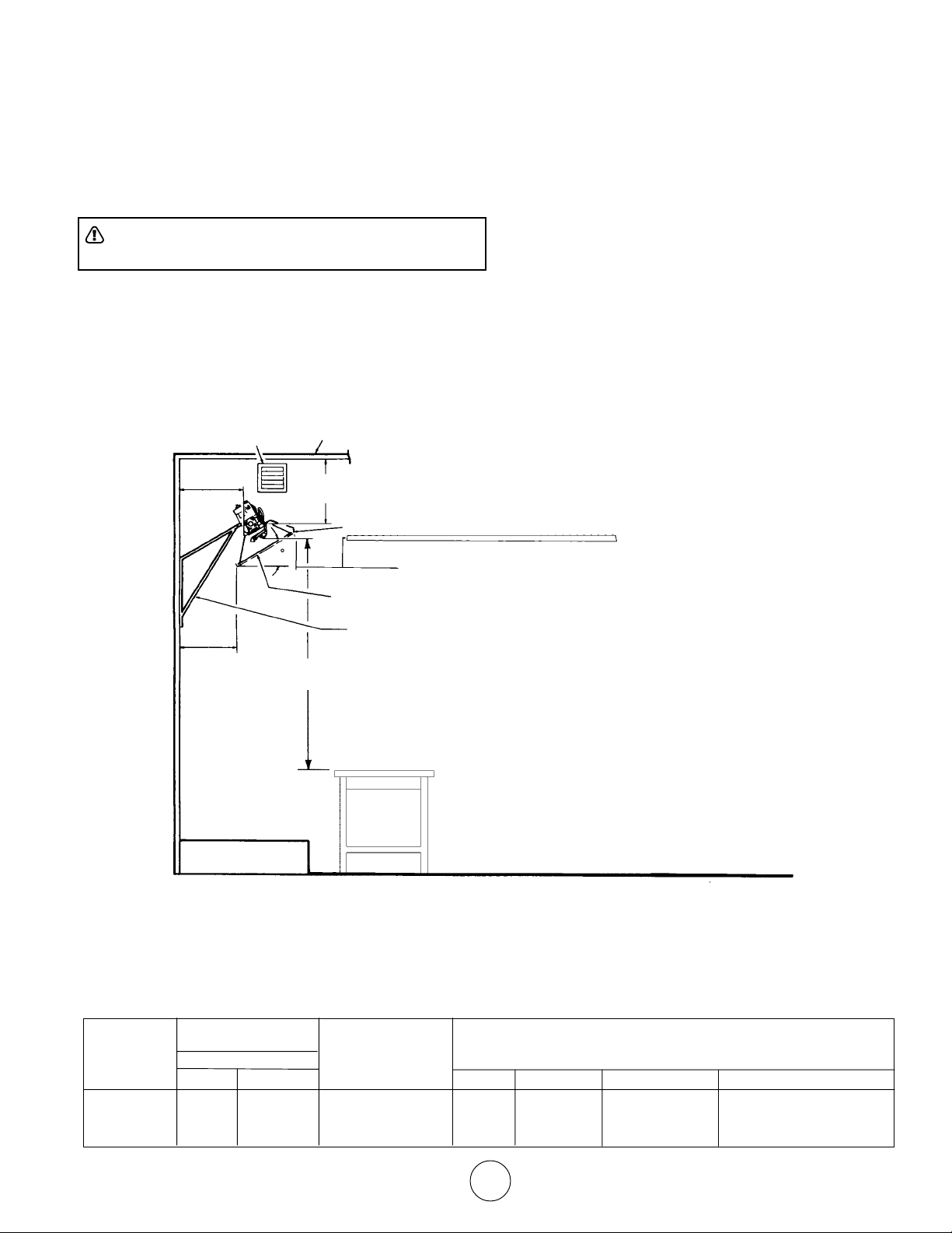
• The required minimum clearances to combustible
surfaces are illustrated in Figure 2 and Table 3.
As shown on Figure 2, the front of the heater is
installed at the minimum required clearance to
combustible surfaces and toward open space,
and then the other sides must have a minimum
clearance of 16 inches to combustible surfaces.
16”
MINIMUM
14-1/2”
EXHAUST
VENT
30
CEILING
14”
MINIMUM
48”
MINIMUM
OPEN
WORKSHOP DOOR
16”
MINIMUM
HEATER
WALL
BRACKET
NOTE:
1. ONLY FLUE SIDE OF HEATER CAN
BE ELEVATED (30o).
2. HEATER SIDE REFLECTOR MUST
BE HORIZONTAL.
FLOOR LINE
Figure 2. Installation Clearances to Combustible Surfaces
Table 3. Installation, Ventilation and Mounting Information
BTU/HR. RATING NORMAL
MODEL GAS MOUNTING CLEARANCES TO COMBUSTIBLE SURFACES
NO. NAT. L.P. POSITION TOP SIDES BACK BELOW
MH/HS25NG 25,000 — 30
MH/HS25LP — 22,000 30
Model # MH25NG/LP HS25NG/LP
o
o
14" 16" 16" 48"
14" 16" 16" 48"
Installation instructions and Owner’s Manual
5
Page 6

• This heater may be mounted on any wall;
however, it is recommended that the heater be
mounted in the middle of the wall opposite any
overhead doors.
• When selecting installation locations for this
heater ensure that the opening of any exterior or
interior doors or windows will not violate minimum clearances or contact any heater components.
• If an overhead door is installed in the building,
verify that the heater is not installed in such a
way as to interfere with door operation and verify
that the door in its open position will not reduce
clearances below the minimum requirements.
Never mount the heater in such a way that
would position the heater above an opened
overhead door.
• In most cases the infiltration around your
uninsulated entry doors and windows will provide
enough air flow for efficient heater operation.
department at 1-800-251-0001.
The selection of the thermostat mounting location is
critical to efficient and effective heater operation.
• The thermostat should be mounted about 5 feet
above the floor where air can circulate freely
around it.
• The thermostat should not be mounted directly
to a cold exterior wall without an insulated
mounting block.
• The thermostat should not be mounted in direct
drafts.
• The thermostat should not be mounted directly
below the installed the heater.
• The thermostat should not be installed at a
distance that is farther from the heater than the
length of the thermostat cable.
Unrestricted air flow during heater operation is essential
to prevent the area above the installed heater from
overheating. If your workshop/utility building is tightly
insulated (including windows, doors, openings, etc.) the
following ventilating methods
must be followed:
• A single exhaust vent is supplied with your
heater for your convenience. This vent must be
located above the heater (preferably at the
highest point in the building interior) and it must
vent to the exterior of the building. An additional
vent is available from the factory for those having
a finished workshop or utility building.
• An intake vent, or equivalent, from the exterior of
the building and having an effective area of 75
square inches must be located below the heater
(preferably within 2 feet of the building’s floor).
• Openings equivalent to intake vent would be:
partially open doors and partially open windows.
• Openings of this size (5 inch by 13 inch, or 3
inch by 25 inch) will prevent dangerous heat
buildup above the heater.
Ensure that no gas lines or electrical wiring or conduits
will interfere with mounting of the heater to the wall.
Depending on local codes and requirements and the
installer’s skill level, the sizing and installation of gas
lines required to supply the heater may require the
assistance of a professional. If in doubt as to these
requirements, discuss the requirements of this manual
with the dealer from whom the heater was purchased
and your gas supplier, or call our customer service
2. HEATER MOUNTING INSTRUCTIONS
After selecting the heater installation location and the
thermostat location and after verifying and ensuring that
all of the above placement requirements are fulfilled,
mount the heater as follows:
A. Determine how you wish to install the vent based on
the construction of the building and your personal
preference. (i.e., do you wish the flanged (finished)
side on the interior or the exterior of the building or
do you want two vents so that both exterior and
interior will be finished?) If needed, order an
additional vent from the factory. Our address and toll
free phone number are on the rear cover of this
manual. Install the vent as follows:
1. See Figure 3 for dimensions and information on
the vent.
2. Select a place as high above the heater as
possible in accordance with the above requirements and ensure that the vent or vents will not
contact or interfere with existing building systems (i.e., ducts, wiring, plumbing, etc.)
3. Place the unfinished side of the vent against the
wall in its elected location and trace its dimensions on the wall with a pencil or other suitable
marker.
4. Cut or otherwise open a hole in the wall, or walls
for finished buildings, having the dimensions of
the unfinished side of the vent.
5. Install the vent or vents as desired and retain
with 4 suitable fasteners through the predrilled
holes in vent flange.
Model # MH25NG/LP HS25NG/LP
Installation instructions and Owner’s Manual
6
Page 7
B. Prepare to install the heater wall mounting bracket
as follows:
1. If the wall mounting bracket is to be attached to
a stud and wallboard wall, refer to Figure 3 for
dimensions, locate a stud, and drill two 1/8" pilot
holes into the stud centerline. Use template for
simplified installation.
2. If the wall mounting bracket is to be attached to
a brick or masonry wall, refer to Figure 3 for
dimensions. Obtain two 1/4 inch (inside
diameter)expansion anchors and determine the
correct drill size to be used with them. Drill
the appropriate size holes in the brick or masonry to accept the anchors.
C. Place the wall mounting bracket on the wall and
align the two through holes on the bracket with the
pilot holes or anchors. Install 1/4 inch by 2-1/2 inch
lag screws through the bracket into the stud or
anchors. Tighten securely.
D. Locate heater mounting clip on back of heater and
select the 1/4" – 20 by 3/4" hex head bolt and 1/4" 20 hex nut.
E. Position the heater as shown in Figure 3 and slide
the heater mounting clip over the bracket and install
the bolt through the clip and bracket.
F. Thread the hex nut onto the bolt and tighten
securely.
G. Ensure that the selected thermostat location meets
all of the above requirements. Refer to the
instructions that come with the thermostat for
additional grounding information and mounting
instruction.
H. If the wall is of stud and wallboard construction, then
use the #6 by 1 inch sheet metal screws, included
with the thermostat, and mount the thermostat in the
selected location.
I. If wall is brick or masonry, the appropriate anchors
must be obtained to accommodate thermostat
mounting screws. Use the back plate of the
thermostat as a template to mark the hole locations,
drill appropriate size anchor holes, install the
anchors, securely attach the thermostat using the
mounting screws.
J. Connect thermostat wires to gas valve as shown in
Figure 4.
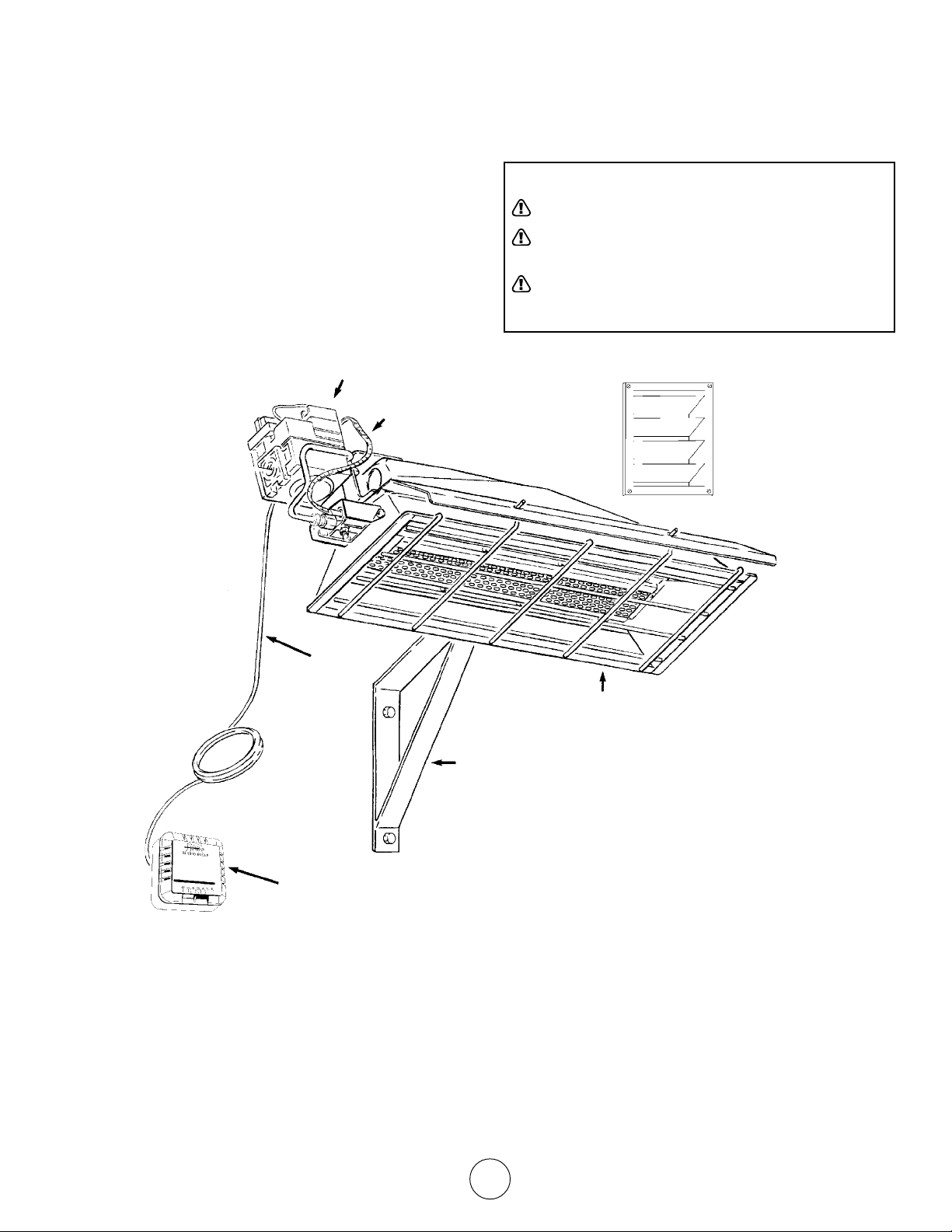
24” MIN
HEATER WALL
MOUNTING
BRACKET
9”
1/4” X 2-1/2” LONG
LAG SCREWS
(2 REQUIRED)
CEILING
HEATER
1/4”-20x3/4”
HEXHEAD BOLT
GAS
CONTROL
VALVE
Figure 3. Heater Mounting Information
MOUNTING
CLIP
1/4”-20
HEX NUT
FLUE
DEFLECTOR
HEATER
REFLECTOR
1/2” NPT GAS INLET
(DO NOT EXCEED 1/2 PSI)
THERMOSTAT CABLE
(SEE FIGURE 4)
58”
FLOOR
Model # MH25NG/LP HS25NG/LP
#6 X 1” SHEET METAL SCREWS
(2 REQUIRED - INCLUDED WITH
THERMOSTAT)
UNFINISHED
SIDE
THERMOSTAT (SEE INSTRUCTIONS
INCLUDED WITH THERMOSTAT
Installation instructions and Owner’s Manual
7
FINISHED
SIDE
FLANGE
PREDRILLED
HOLES
Page 8
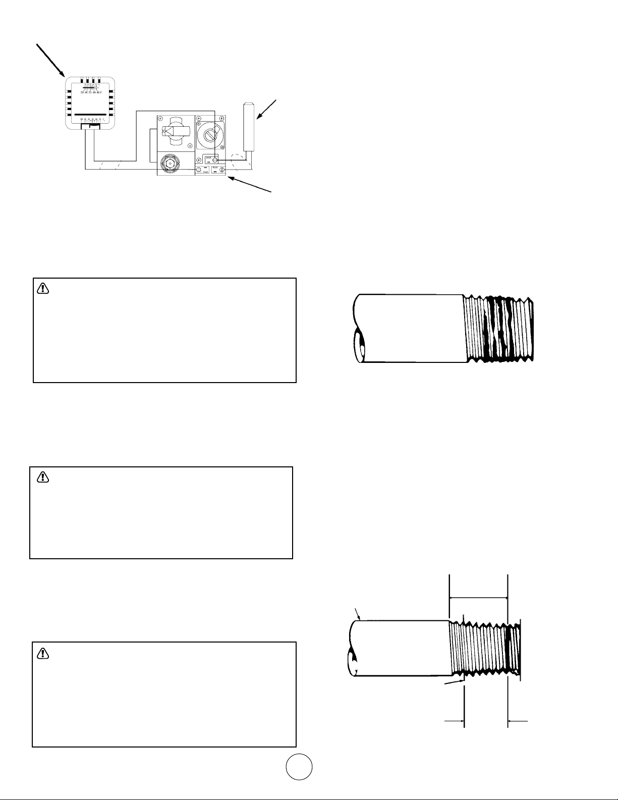
THERMOSTAT
• To ensure the best performance from your LP gas
heater, make sure the supply manifold pressure is
at least 1/2 psi (14 in W.P.).
POWERPILE GAS VALVE
POWERPILE GENERATOR
Figure 4. Connection Diagram
Refer to National Electrical Code NFPA70-1993 and for
Canadian installations to current CODE C22.1-
3. CONNECTING HEATER TO GAS SUPPLY
WARNING: Depending on local codes and require-
ments and the installer’s skill level, the sizing and
installation of gas lines required to safely and efficiently
supply the heater may require the assistance of a
professional. If in doubt as to these requirements,
discuss the requirements of this manual with the dealer
from whom the heater was purchased and your gas
supplier.
3.2 Piping Requirements
All piping installed must comply with local codes and
ordinances or with National Fuel Gas Code,
ANSI Z223.1 (NFPA 54), whichever takes precedence.
When installing piping, the following requirements must be
taken into consideration: Canadian installations must
comply with the B149.1.2 Gas Code.
• Use new properly reamed black pipe free from
chips.
• Apply a good quality pipe compound to all male
threads as shown in Figure 5 prior to assembly. If
LP gas is the fuel, ensure that pipe compound is
resistant to LP gas. Do not use Teflon™ tape.
USE MODERATE AMOUNT OF PIPE DOPE
LEAVE 2 THREADS BARE
3.1 Gas Supply Requirements
• See Tables 1 and 2 for gas supply minimum,
maximum, operating, and manifold pressures for
both heater models. Pressures are provided in
inches of W.C. (water column). Also, see heater
rating plates located on the heater.
WARNING: Model MH/HS25NG is designed to burn
natural gas and it comes equipped with a regulator. The
regulator is built into the gas valve. The maximum inlet
pressure to this regulator is 1/2 psi (14 in. W.C.) If gas
line pressure exceeds 1/2 psi, then an additional
regulator must be installed before the heater/regulator
to step down the pressure to a maximum of 1/2 psi.
• Most residential natural gas services provide a line
pressure of 4 oz. (6.9 in. W.C.). If in doubt consult
your natural gas supplier.
• To ensure the best performance from your natural
gas heater make sure the supply manifold pressure is at least 6" W.C.
WARNING: Model MH/HS25LP is designed to burn
liquefied petroleum (LP) gas and it comes equipped
with a regulator. The regulator is built into the gas valve.
The maximum inlet pressure to this regulator is 1/2 psi
(14 in. W.C.). If gas line pressure exceeds 1/2 psi, then
an additional regulator must be installed before the
heater/regulator to step down the pressure to a maximum of 1/2 psi.
Figure 5. Pipe Compound Application
• Male threads on pipe to be installed into gas valve
shall meet the requirements of Figure 6. Threads
longer than those shown in the figure may cause
gas valve distortion and malfunction.
• A sediment trap meeting the typical requirements
of Figure 7 shall be installed in the line to the gas
valve.
• A dedicated shutoff valve for the heater must be
installed in the gas supply line.
3.3 Piping Installation
While ensuring that all of the above gas supply require-
3/4” MAXIMUM
THREAD LENGTH
1/2” BLACK PIPE
GAS VALVE BODY
1/2” MAXIMUM
DEPTH OF INSERTS
INTO GAS VALVE
Figure 6. Gas Valve Connection Requirements
Model # MH25NG/LP HS25NG/LP
Installation instructions and Owner’s Manual
8
Page 9
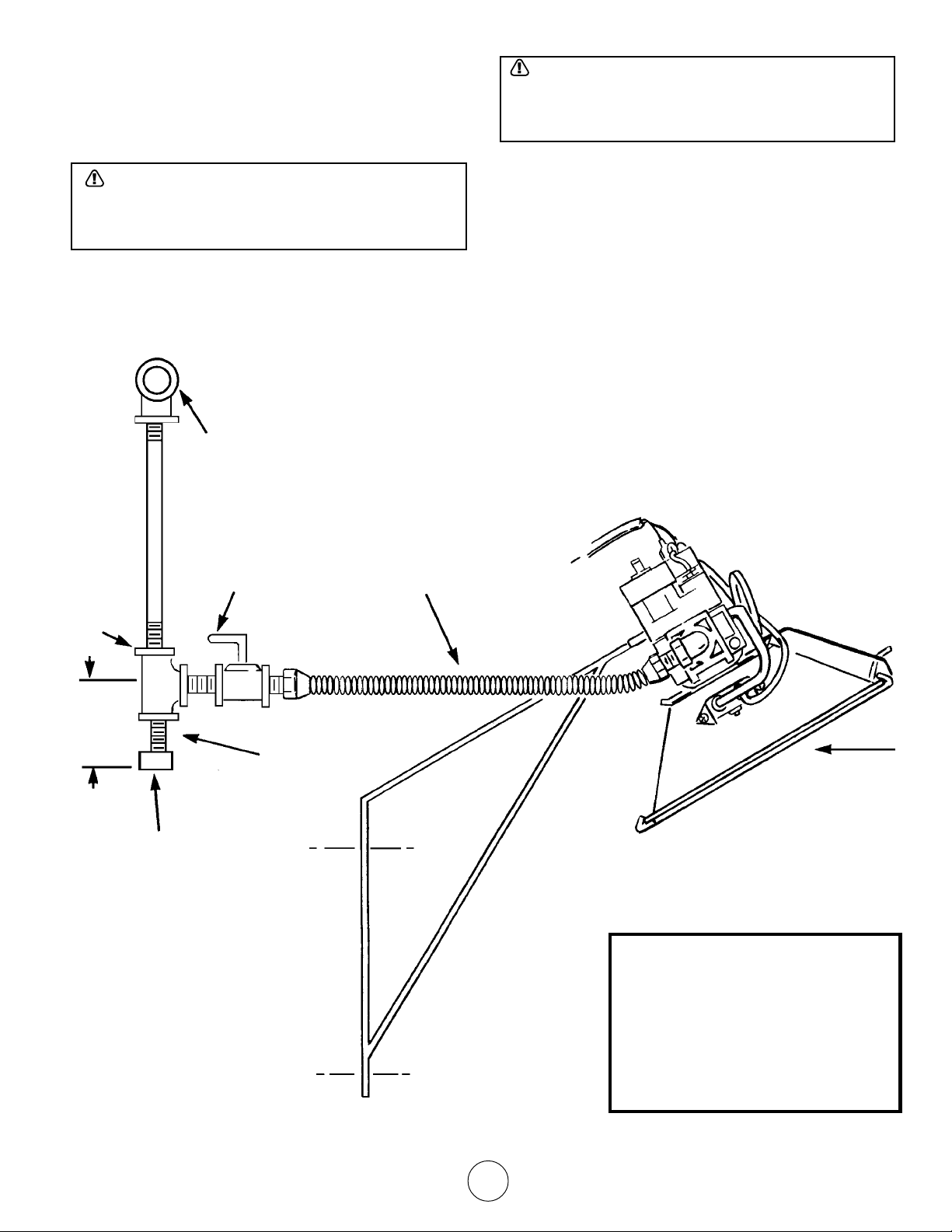
ments and piping requirements are fulfilled, install piping
as follows:
A. In accordance with the above piping requirements,
assemble piping, sediment trap, shutoff valve, and
necessary fittings. Tighten all components securely.
WARNING: Failure to ensure that male threads on
pipe to be installed into gas valve meet the requirements of Figure 6 may cause gas valve damage,
distortion and malfunction.
B. Install a threaded nipple, prepared in accordance
with paragraph 3.2 into gas valve.
C. Connect gas piping to nipple installed in the gas
valve.
SUPPLY
LINE
WARNING: When testing gas piping use only a soap
and water solution. Do not use a match or other flame
for leak testing. If during leakage check gas is
smelled, turn off the gas supply and ventilate building.
D. Ensure the building is properly ventilated. Without
lighting the pilot light of the heater, open the gas
supply valve and pressurize the piping up to the
heater’s gas valve.
E. Using a brush, apply a soap and water solution to all
connections and look for bubbles indicating a leak. If
a leak is detected, turn off gas supply and tighten
connections. Retest and tighten connections until no
more leaks are found.
1/2”
TEE
3”
CAP
SHUTOFF
VALV E
NIPPLE
RIGID PIPE WITH
UNION OR A FLEXIBLE
CONNECTOR TO HEATER
HEATER
NOTE:
1. ONLY USE A PIPE COMPOUND
WHICH IS RESISTANT TO
LIQUIFIED GASES ON LP
INSTALLATIONS.
2. FITTINGS SHOWN ARE NOT
INCLUDED WITH HEATER.
Figure 7. Typical Piping Installation
Model # MH25NG/LP HS25NG/LP
Installation instructions and Owner’s Manual
9
Page 10
CHAPTER III
HEATER OPERATING
INSTRUCTIONS
NOTE
Gasket binder material used in this heater assembly
will temporarily emit an odor and/or vapor. This condition will clear up in approximately 20 minutes and
thereafter will not reoccur. Refer to Chapter 2 for
ventilation.
1. OPERATING SAFETY INSTRUCTIONS
WARNING: When used without fresh air, heater may
give off CARBON MONOXIDE, an odorless poisonous gas. OPEN WINDOW AN INCH OR TWO FOR
FRESH AIR WHEN USING HEATER.
WARNING: This heater is equipped with a PILOT
LIGHT SAFETY SYSTEM. DO NOT TAMPER WITH
PILOT LIGHT SAFETY SYSTEM.
WARNING: If heater shuts off, do not relight until you
provide fresh air. Open door for 5 minutes. If heater
keeps shutting off, have it serviced. Keep burner and
control clean.
WARNING: CARBON MONOXIDE POISONING MAY
LEAD TO DEATH. Early signs of carbon monoxide
poisoning resemble the flu with headache, dizziness
and/or nausea. If you have these signs, heater may
not be working properly. Get fresh air at once! Have
heater serviced.
WARNING: DO NOT USE MATCH OR OTHER
FLAME FOR LEAK TESTING.
CAUTION: If the infra-red color of the grid becomes
dull when the building furnace is operating, consult
gas supplier on correct gas supply piping sizes.
CAUTION: This heater is for indoor installation only!
2. HEATER STARTUP
WARNING: During heater startup ensure that
building is well ventilated.
A. Open the gas supply valve or valves.
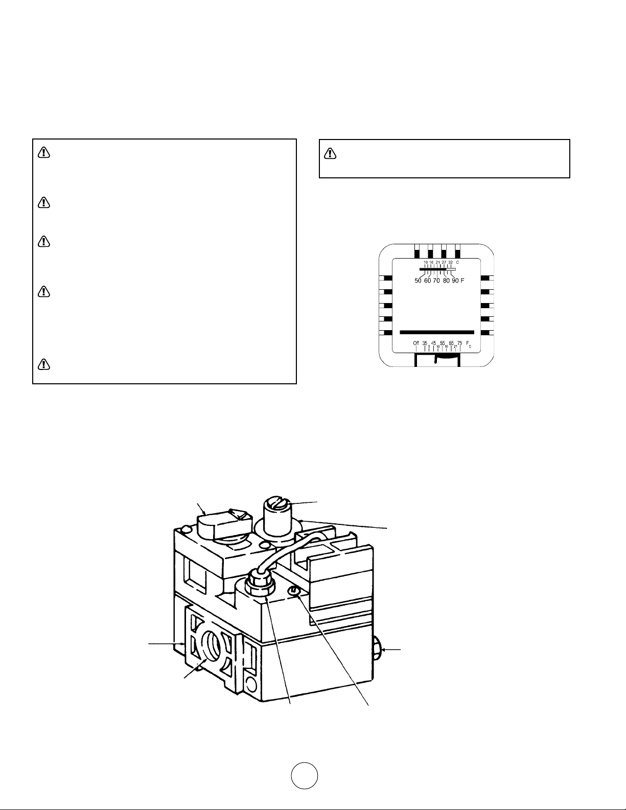
B. Set the thermostat to the OFF position.
See Figure 8.
FIGURE 8. THERMOSTAT CONTROLS
C. If the manual gas control knob on the gas valve is
not in the OFF position, partially depress the knob
and rotate to the OFF position. See Figure 9.
MANUAL GAS
CONTROL KNOB
WRENCH
BOSS
GAS
INLET
Model # MH25NG/LP HS25NG/LP
PRESSURE
REGULATOR
ADJUSTMENT
PILOTSTAT
POWER UNIT
PILOT FLOW ADJUSTING SCREW
(BENEATH COVER SCREW)
Figure 9. Gas Valve Components
Installation instructions and Owner’s Manual
10
STANDARD
PRESSURE
REGULATOR
PILOT GAS OUTLET
(PRESSURE TAPPING
DIRECTLY BENEATH)
Page 11

D. Wait 5 minutes to allow gas that may have
accumulated in the main burner to escape
(especially important after installation).
E. Turn the manual gas control knob to the PILOT
position.
F. Depress the manual gas control knob. Using a
match, light the pilot light. See Figure 10. Hold the
knob down for approximately 30 seconds to allow
any air in gas lines to pass through pilot and, once
pilot is lit, allow the thermocouple to heat up enough
to activate the safety valve in an open position.
G. Release manual gas control knob and turn to ON.
H. Reset thermostat to desired temperature.
DEPRESS TO
LIGHT
NOTE
During the initial startup of heater, an odor and,
perhaps, some vapor will come from the heater. This
is the gasket binding material emitting this odor and/
or vapor. After approximately 20 minutes, this odor will
disappear and not occur again.
3. HEATER SHUTDOWN
A. Turn thermostat to OFF.
B. Turn manual gas control knob on gas valve to PILOT
position.
C. Partially depress knob and rotate to the OFF
position.
D. Close gas supply valves.
GAS VALVE
PILOT BURNER
Figure 10. Lighting of Pilot Burner
Model # MH25NG/LP HS25NG/LP
11
LIGHT PILOT WITH MATCH
AS SHOWN
Installation instructions and Owner’s Manual
Page 12

CHAPTER IV
OPERATOR MAINTENANCE
INSTRUCTIONS
PROPER FLAME
ADJUSTMENT
3/8 TO 1/2 INCH
(10-13 MILLIMETERS)
1. TROUBLESHOOTING
A. Table 4 lists the common malfunctions which you may
find during the operation or maintenance of your heater.
B. For additional information, refer to Honeywell Field
Bulletin enclosed in the heater carton.
C. In the event results cannot be obtained after performing
all listed solutions, call the factory.
2. ADJUSTING THE PILOT FLAME
The pilot flame should envelop 3/8 to 1/2 in. (10 to 13
mm) of the tip of the thermocouple or generator.
Refer to Figure 11. To adjust:
PRESSURE REGULATOR ADJUSTMENT
MANUAL GAS
CONTROL KNOB
WRENCH
BOSS
Figure 11. Proper Flame Adjustment
A. Remove pilot adjustment cover screw. Refer to
Figure 12.
B. Turn inner adjustment screw clockwise to
decrease or counterclockwise to increase
pilot flame.
C. Always replace cover screw after adjustment and
tighten firmly to ensure proper operation.
(BENEATH COVER SCREW)
INSTALL LONG
SCREW IN
OUTSIDE CORNER
THERMOCOUPLE
GAS
INLET
PILOTSTAT
POWER UNIT
Figure 12. Top View of Standard Capacity Gas Control
Model # MH25NG/LP HS25NG/LP
STANDARD
PRESSURE
REGULATOR
(“A” MODEL)
STEP OPENING REGULATOR
PILOT GAS OUTLET
(PRESSURE TAPPING
DIRECTLY BENEATH)
PILOT FLOW ADJUSTING SCREW
(BENEATH COVER SCREW)
Installation instructions and Owner’s Manual
12
(“C” MODEL)
Page 13

Table 4. Trouble Shooting Chart
Below in chart form are various symptoms of a malfunctioning system, possible defects that will cause these symptoms
and suggested corrective measures. The chart assumes that the proper gas pressure is available to the heater and that
the lighting procedure is as stated on the plate attached to the heater.
SYMPTOMS CAUSES SOLUTIONS
burner light off very slow partially block pilot orifice replace
burner light off very slow infra-red partially blocked burner orifice replace
color stays dull
burner flash back low gas pressure correct line pressure
(roaring noise during operation or call your gas supplier
and ceramic grid surface will be
dark) damaged burner replace
ceramic grid or burner sooting up first check for damaged burner replace if damaged
(when new or after cleaning) orifice
pilot cannot be ignited blocked pilot orifice replace
pilot out of adjustment re-adjust pilot
if burner orifice is not damaged replace
then check for damaged manifold
gas cock not in position gas cock knob must be
turned to pilot and held
depressed
pilot gas flow adjustment open and adjust
screw may be closed (see Figure 12)
pilot lights but goes out defective thermocouple replace
defective control replace
pilot stays lit but main burner loose wire or improperly wired tighten connections, check
will not light wiring diagram
defective control replace
blocked burner orifice clean orifice or replace
failure to ignite main gas off open manual valves
3. REPLACING THE GAS VALVE UNIT
A. Remove the two gas valve unit wires at the gas
control valve labeled “PP”.
B. Unscrew gas valve from gas piping.
C. Reconnect gas valve and unit wires to terminals
“PP”. Be sure to leave thermostat wire on one
terminal.
4. FREQUENCY OF OPERATOR CHECKS
Intermittent use. Appliances that are used seasonally
air in gas line bleed gas line
loose wire connections tighten wire connections
dirty wire connections clean terminals and secure
terminals
should be checked before shutdown and again before the
next use.
Dusty, wet or corrosive environment. Since these
environments can cause the gas control to deteriorate
more rapidly, the system should be checked more often.
The gas control should be replaced if:
A. It does not perform properly on checkout or trouble
shooting.
B. The gas control knob Is hard to turn or push down, or
it fails to pop back up when released.
Model # MH25NG/LP HS25NG/LP
13
Installation instructions and Owner’s Manual
Page 14

IF SERVICE IS REQUIRED
PLEASE DO NOT RETURN THIS APPLIANCE TO YOUR STORE
For information regarding service, please call our Toll-Free Number:
1-800-251-0001.
Our office hours are 8:30 AM – 5:00 PM, Eastern Time Zone
Monday through Friday
Please include the model number, date of purchase, and description of
problem in all communication.
CHAPTER V
REPLACEMENT PARTS LIST
1.INTRODUCTION
This section of the manual will help you to obtain
efficient and dependable service from your heater and
enable you to order repair parts correctly.
A. Order parts by giving full model number and serial
number as it is stated on the name place attached
to the heater.
B. See Figure 13 to assist in locating parts.
C. Refer to Table 5 for part number and description.
2.WARRANTY
Enerco Group, Inc. warrants that Infra-Red Heaters
manufactured and sold will be free from defects in
material and workmanship.
Parts, assemblies, controls, etc. furnished by EGI
suppliers will carry a one (1) year warranty from date of
purchase.
The sole responsibility of EGI under this warranty shall be
to replace any part for which a written claim is made to
EGI WITHIN THE TIME LIMIT OF THIS WARRANTY,
WHICH IS RETURNED UPON REQUEST TO EGI –
F.O.B. Cleveland, Ohio – OR F.O.B. an EGI authorized
service facility and which is proved to be defective upon
inspection by EGI.
This warranty shall not apply to any part or product which
has been subjected to misuse or neglect, damaged by
accident, or rendered defective by reason of improper
installation. THIS WARRANTY IS IN LIEU OF ANY AND
ALL OTHER WARRANTIES, EXPRESSED OR IMPLIED,
and of any other responsibility of EGI for parts or products
sold by EGI, including consequential or special damages.
Model # MH25NG/LP HS25NG/LP
Installation instructions and Owner’s Manual
14
Page 15

1
11
12
8
20
21
3
18
19
2
22
15
5
6
7
10
16
17
4
13
14
9
Table 5. Replacement Parts List for Heater Models MH/HS25NG and MH/HS25LP
ITEM NO. STOCK NO. DESCRIPTION ITEM NO. STOCK NO. DESCRIPTION
1 02529A Burner Assembly Complete 12 05455 Orifice-Burner-Propane Gas
2 00377A Reflector Assembly 13 05576 Orifice-Pilot-Natural Gas
3 01357 Flue Deflector 14 05573 Orifice-Pilot-Propane Gas
4 16451 Pilot Tube 15 10358 Thermostat Cable
5 00024 Gas Valve-Natural Gas 16 11406 Pilot Burner N/G
6 00025 Gas Valve-Propane Gas 17 11405 Pilot Burner L/P
7 10367 Thermostat 18 04435A Grid Replacement
8 14405 Wall Mounting Bracket 19 12369 Gasket
9 04432 Face Guard 20 05354 Jamb Nut
10 09360 Thermocouple/Generator 21 05351 Connector
11 05445 Orifice-Burner-Natural Gas 22 98593 3/8” Close Nipple
23 19014 Intake Louver
23
ALL WARRANTY CLAIMS REQUIRE PROOF OF PURCHASE
Model # MH25NG/LP HS25NG/LP
15
Installation instructions and Owner’s Manual
Page 16

WARRANTY INFORMATION
Keep this warranty
Model ______________________
Serial No. ___________________
Date Purchased _______________
Always specify model and serial numbers when communication with the factory.
We reserve the right to amend these specifications at any time without notice. The only warranty applicable
is our standard written warranty. We make no other warranty, expressed or implied.
Enerco Group, Inc. warrants this product to be free from defects in materials and components for two (2)
years from the date of first purchase, provided that the product has been properly installed, operated and
maintained in accordance with all applicable instructions. To make a claim under this warranty the Bill of
Sale or cancelled check must be presented.
The warranty is extended only to the original retail purchaser. This warranty covers the cost of part(s)
required to restore the heater to proper operating condition and an allowance for labor when provided by an
Enerco Group, Inc. Authorized Service Center. Warranty part(s) MUST be obtained through authorized
dealers of this product and/or Enerco Group, Inc. who will provide original factory replacement parts. Failure
to use original factory parts voids this warranty. The heater MUST be installed by a qualified installer in
accordance with all local codes and instructions furnished with the unit.
This warranty does not apply to parts that are not in original condition because of normal wear and tear of
parts that fail or become damaged as a result of misuse, accidents, lack of proper maintenance or defects
caused by improper installation. Travel, diagnostic cost, labor, transportation and any and all such costs
related to repairing a defective heater will be the responsibility of the owner.
TO THE FULL EXTENT ALLOWED BY THE LAW OF THE JURISDICTION THAT GOVERNS THE SALE
OF THE PRODUCT; THIS EXPRESS WARRANTY EXCLUDES ANY AND ALL OTHER EXPRESSED
WARRANTIES AND LIMITS THE DURATION OF ANY AND ALL IMPLIED WARRANTIES OF MERCHANTABILITY AND FITNESS FOR A PARTICULAR PURPOSE, TO TWO (2) YEARS OF ALL COMPONENTS
FROM THE FIRST DATE OF PURCHASE; AND ENERCO GROUP, INC.’S LIABILITY IS HEREBY LIMITED
TO THE PURCHASE PRICE OF THE PRODUCT AND ENERCO GROUP, INC. SHALL NOT BE LIABLE
FOR ANY OTHER DAMAGES WHATSOEVER INCLUDING INDIRECT, INCIDENTAL OR CONSEQUENTIAL DAMAGES.
Some states do not allow a limitation on how long an implied warranty lasts or an exclusion or limitation on
incidental or consequential damages, so the above limitation on implied warranties, or limitation on damages, may not apply to you.
This warranty gives you specific legal rights, and you may also have other rights that very from state to
state. Always specify model and serial number when communication with the factory.
ENERCO GROUP, INC., 4560 W. 160TH ST., CLEVELAND, OHIO 44135
216-916-3000 Toll Free Number 1-800-251-0001
www.mrheater.com
Mr. Heater is a registered trademark of Enerco Group, Inc.
© 2005, Enerco/Mr. Heater. All rights reserved
Model # MH25NG/LP HS25NG/LP
Installation instructions and Owner’s Manual
16
®
CAN 1-2.16-M81
ANSI Z83.6b-1993
Page 17

ANSI Z83.6b-1993
CAN 1-2.16-M81
®
16
Notice d’installation et guide d’utilisation
Modèle n° MH25NG/LP HS25NG/LP
© Enerco/Mr. Heater, 2005. Tous droits réservés.
Mr. Heater est une marque déposée d’Enerco Group, Inc.
www.mrheater.com
216 916-3000 Numéro sans frais 1 800 251-0001
ENERCO GROUP, INC., 4560 W. 160TH ST., CLEVELAND, OHIO 44135
communications avec l’usine.
droits qui varient selon la province ou l’État. Précisez toujours le modèle et le numéro de série dans vos
La présente garantie vous accorde des droits juridiques précis, et vous pourriez également avoir d’autres
ci-dessus sur les garanties implicites ou sur les dommages ne s’applique pas à vous.
exclusion ou une limitation sur les dommages accessoires et consécutifs; ainsi, il est possible que la limite
Certaines province ou certains États ne permettent pas une limite de durée de garantie implicite ni une
ACCESSOIRE OU CONSÉCUTIF.
PRODUIT; ENERCO GROUP, INC. NE SERA RESPONSABLE D’AUCUN AUTRE DOMMAGE INDIRECT,
RESPONSABILITÉ D’ENERCO GROUP, INC. EST PAR LA PRÉSENTE LIMITÉE AU PRIX D’ACHAT DU
DEUX (2) ANS POUR TOUS LES COMPOSANTS À PARTIR DE LA DATE DU PREMIER ACHAT; ET LA
DE TOUTES LES GARANTIES IMPLICITES DE QUALITÉ MARCHANDE ET D’APTITUDE À L’USAGE À
CETTE GARANTIE EXPRESSE EXCLUT TOUTE AUTRE GARANTIE EXPRESSE ET LIMITE LA DURÉE
AVEC TOUTE LA RIGUEUR DE LA LOI DU TERRITOIRE GOUVERNANT LA VENTE DU PRODUIT,
toutes les dépenses reliées à la réparation d’un radiateur défectueux seront à la charge du propriétaire.
mauvaise installation. Les frais de déplacement, de diagnostic, de main-d’œuvre et de transport, ainsi que
ou endommagées en raison d’un usage abusif, d’un accident, ou bien d’un entretien inadéquat ou d’une
Cette garantie ne s’applique pas aux pièces soumises à une usure normale ni aux pièces défectueuses
locaux et à la notice d’installation fournie avec l’appareil.
cette garantie. Le radiateur DOIT être installé par un installateur qualifié conformément à tous les codes
rechange originales de l’usine. Le défaut d’utiliser des pièces originales de l’usine aura pour effet d’annuler
auprès des détaillants autorisés de ce produit et/ou d’Enerco Group, Inc., qui fournira les pièces de
centre de réparations autorisé par Enerco Group, Inc.. Les pièces garanties DOIVENT être obtenues
pièces requises pour rétablir le bon fonctionnement du radiateur et, s’il y a lieu, celui de la main-d’œuvre du
La garantie ne protège que l’acheteur initial auprès du détaillant. Cette garantie couvre le coût de la ou des
garantie, un contrat de vente ou un chèque annulé doit être présenté.
utilisé et entretenu conformément aux directives applicables. Pour faire une réclamation en vertu de cette
deux (2) ans à partir de la date de l’achat initial, à la condition que ce produit ait été correctement installé,
Enerco Group, Inc. garantit ce produit contre tout défaut de matériel et de fabrication pour une période de
applicable est notre garantie écrite standard. Nous n’offrons aucune autre garantie, expresse ou implicite.
Nous nous réservons le droit de modifier ces spécifications en tout temps sans préavis. La seule garantie
Précisez toujours le modèle et le numéro de série dans vos communications avec l’usine.
Date de l’achat _______________
Numéro de série ___________________
Modèle ______________________
Conservez cette garantie
RENSEIGNEMENTS SUR LA GARANTIE
Page 18

combustion
brûleur
Notice d’installation et guide d’utilisation
15
PREUVE D’ACHAT
23 19014 Évent à lames
Modèle n° MH25NG/LP HS25NG/LP
TOUTES LES RÉCLAMATIONS EN VERTU DE LA GARANTIE REQUIÈRENT UNE
11 05445 Orifice-brûleur-gaz naturel 22 98593 Raccord simple 3/8 po
10 09360 Thermocouple/générateur 21 05351 Connecteur
9 04432 Grille de protection 20 05354 Contre-écrou
8 14405 Support mural 19 12369 Joint d’étanchéité
7 10367 Thermostat 18 04435A Grille de rechange
5 00024 Soupape de gaz-gaz 16 11406 Veilleuse GN naturel
5 00024 Soupape de gaz-gaz 16 11406 Veilleuse GN naturel
4 16451 Tube de veilleuse 15 10358 Câble du thermostat
3 01357 Déflecteur de gaz de 14 05573 Orifice-veilleuse-gaz propane
2 00377A Ensemble de réflecteur 13 05576 Orifice-veilleuse-gaz naturel
1 02529A Ensemble complet de 12 05455 Orifice-brûleur-gaz propane
CLATURE CLATURE
N° D’ARTICLE N° DE NOMEN- DESCRIPTION N° D’ARTICLE N° DE NOMEN- DESCRIPTION
MH/HS25NG et MH/HS25LP
Tableau 5 Liste des pièces de remplacement pour les modèles de radiateurs
14
13
23
17
16
9
2
19
18
4
10
22
20
12
7
6
5
15
21
8
11
3
1
Page 19

14
Notice d’installation et guide d’utilisation
dommages consécutifs ou spéciaux.
des pièces ou des produits vendus par EGI, incluant les
IMPLICITE, et toute autre responsabilité d’EGI en regard
REMPLACE TOUTE AUTRE GARANTIE EXPRESSE OU
raison d’une mauvaise installation. CETTE GARANTIE
accidentellement endommagés ou défectueux en
un produit négligés ou dont on a fait un usage abusif,
Cette garantie ne protège aucunement une pièce ou
pièce est défectueuse.
EGI autorisé, si EGI détermine après inspection que la
Cleveland, en Ohio – OU FOB à un centre de réparations
ÊTRE RETOURNÉE SUR DEMANDE À EGI – FOB à
PÉRIODE DE GARANTIE, CETTE PIÈCE DEVANT
réclamation écrite est soumise à EGI DURANT LA
consiste à remplacer toute pièce pour laquelle une
En vertu de cette garantie, la seule responsabilité d’EGI
.
Modèle n° MH25NG/LP HS25NG/LP
garantie d’un (1) an à partir de la date d’achat.
fournis par les fournisseurs d’EGI comportent une
Les pièces, les ensembles, les commandes, etc.,
fabrication.
fabriqués et vendus contre les défauts de matériel et de
Enerco Group, Inc. garantit les radiateurs à infrarouge
2. GARANTIE
description des pièces
C. Reportez-vous au tableau 5 pour le numéro et la
B. Consultez la figure 13 pour repérer les pièces.
sur la plaque signalétique du radiateur.
complet du modèle et le numéro de série indiqués
A. Pour commander les pièces, indiquez le numéro
commander les pièces correctement.
rendement fiable et efficace de votre radiateur et à
La présente section du manuel vous aidera à obtenir un
1. INTRODUCTION
LISTE DES PIÈCES DE RECHANGE
CHAPITRE V
problème dans toutes vos communications.
Veuillez inclure le numéro de modèle, la date de l’achat et la description du
du lundi au vendredi
Nos heures d’ouverture sont de 8 h 30 à 17 h, HE,
numéro sans frais : 1 800 251-0001.
Pour plus de renseignements sur les réparations, veuillez appeler notre
NE RETOURNEZ PAS CET APPAREIL À VOTRE MAGASIN
SI UNE RÉPARATION EST NÉCESSAIRE
Page 20

Notice d’installation et guide d’utilisation
13
remonte pas lorsque relâché.
de la commande de gaz, ou si le bouton ne
B. Il est difficile de tourner ou d’enfoncer le bouton
l’inspection ou du dépannage.
A. Elle ne fonctionne pas correctement lors de
La commande de gaz doit être remplacée si :
doit être inspecté plus souvent.
détérioration rapide de la commande de gaz, le système
Puisque ce type d’environnement peut entraîner une
Environnement poussiéreux, humide ou corrosif.
fils de raccordement encrassés nettoyer et serrer les bornes
fils de raccordement relâchés serrer les fils de raccordement
air dans la conduite de gaz purger la conduite de gaz
orifice du brûleur bloqué nettoyer l’orifice ou remplacer
commande défectueuse remplacer
Modèle n° MH25NG/LP HS25NG/LP
et avant leur mise en fonction à la saison suivante.
saisonnière doivent être inspectés avant leur mise à l’arrêt
Usage intermittent. Les appareils utilisés sur une base
L’UTILISATEUR
4. FRÉQUENCE DES INSPECTIONS PAR
le fil du thermostat sur une borne.
soupape aux bornes «PP». Assurez-vous de laisser
C. Reconnectez la soupape de gaz et les fils de la
B. Dévissez la soupape de gaz du tuyau.
de gaz.
A. Déposez les deux fils étiquetés «PP» à la soupape
3. REMPLACEMENT DE LA SOUPAPE DE GAZ
allumage impossible gaz secteur coupé ouvrir les robinets manuels
ne s’allume pas le schéma de câblage
mais le brûleur principale inadéquats mais le brûleur principal
la veilleuse demeure allumée fils de raccordement relâchés ou serrer les connexions, vérifier
tourné à PILOT et tenu enfoncé
commande défectueuse remplacer
la veilleuse s’allume puis s’éteint thermocouple défectueux remplacer
la veilleuse est peut-être fermée (voir la figure 12)
la vis de réglage du débit de gaz à ouvrir et régler
robinet de gaz pas en position le bouton du robinet doit être
impossible d’allumer la veilleuse orifice de la veilleuse bloqué remplacer
est endommagé
endommagé vérifier si le collecteur
si l’orifice du brûleur n’est pas remplacer
neufs ou viennent d’être nettoyés)
noirs de suie (alors qu’ils sont est endommagé
grille en céramique ou brûleur vérifier d’abord si l’orifice du brûleur remplacer si endommagé
brûleur endommagé remplacer
grille en céramique est sombre)
radiateur et la surface de la
(fonctionnement bruyant du ou appeler le fournisseur en gaz
retour de flamme du brûleur pression insuffisante du gaz corriger la pression dans la conduite
demeure terne
I la couleur de l’infrarouge veilleuse
allumage très lent de la veilleuse, obturation partielle de l’orifice de la remplacer
veilleuse, veilleuse mal réglée régler de nouveau la veilleuse
allumage très lent de la veilleuse obturation partielle de l’orifice de la remplacer
SYMPTÔMES CAUSES SOLUTIONS
procédure d’allumage est conforme à celle indiquée sur la plaque rattachée au radiateur.
les mesures correctives suggérées. Le tableau suppose que la pression du gaz combustible est appropriée et que la
Le tableau suivant présente différents symptômes d’un système défectueux, les causes possibles de ces symptômes et
Tableau 4. Tableau de dépannage
Page 21

DIRECTEMENT EN DESSOUS)
(DÉRIVATION DE PRESSION
SORTIE DE GAZ DE VEILLEUSE
(MODÈLE «C»)
PROGRESSIVE
RÉGULATEUR À OUVERTURE
Notice d’installation et guide d’utilisation
(MODÈLE «A»)
STANDARD
DE PRESSION
RÉGULATEUR
12
vue du dessus
COUVERCLE)
Figure 12. Commande de gaz de capacité standard –
VEILLEUSE
VEILLEUSE (SOUS LA VIS DU
VIS DE RÉGLAGE DU DÉBIT DE LA
DU CAPTEUR DE
DE GAZ
ENTRÉE
Modèle n° MH25NG/LP HS25NG/LP
BLOC D’ALIMENTATION
LE COIN EXTÉRIEUR
LONGUE VIS DANS
INSTALLEZ UNE
pour l’augmenter.
flamme
(SOUS LA VIS DU COUVERCLE)
PRESSION
RÉGLAGE DU RÉGULATEUR DE
fonctionnement de la veilleuse.
réglage en la serrant bien pour assurer le bon
C. Remettez toujours la vis du couvercle après le
et dans le sens antihoraire
pour réduire la flamme de la veilleuse
horaire
B. Tournez la vis de réglage interne dans le sens
veilleuse. Voir la figure 12.
A. Déposez la vis du couvercle de réglage de la
Figure 11. Réglage approprié de la
MANOEUVRE
BOSSAGE DE
GAZ MANUELLE
COMMANDE DE
BOUTON DE
ou du générateur. Voir la figure 11. Pour le réglage :
13 mm (3/8 à 1/2 po) de la pointe du thermocouple
La flamme de la veilleuse doit envelopper 10 à
2. RÉGLAGE DE LA FLAMME DE LA VEILLEUSE
de régler le problème, appelez l’usine.
C. Si toutes les solutions énumérées ne permettent pas
technique Honeywell inclus dans la boîte du radiateur.
B. Pour plus de renseignements, consultez le bulletin
le fonctionnement ou l’entretien de votre radiateur.
A. Le tableau 4 énumère les défaillances courantes durant
1. DÉPANNAGE
THERMOCOUPLE
(3/8 À 1/2 POUCE)
10 À 13 MILLIMÈTRES
LA FLAMME
APPROPRIÉ DE
RÉGLAGE
L’UTILISATEUR
À L’INTENTION DE
DIRECTIVES D’ENTRETIEN
CHAPITRE IV
Page 22

Notice d’installation et guide d’utilisation
11
Figure 10. Allumage de la veilleuse
Modèle n° MH25NG/LP HS25NG/LP
QU’INDIQUÉ
AVEC UNE ALLUMETTE TEL
ALLUMER LA VEILLEUSE
VEILLEUSE
REMARQUE
GAZ
SOUPAPE DE
D. Fermez les robinets d’alimentation en gaz.
position OFF (arrêt).
C. Enfoncez légèrement le bouton et tournez-le à la
la position PILOT (veilleuse).
B. Tournez le bouton de commande manuelle du gaz à
A. Mettez le thermostat hors fonction (OFF).
3. ARRÊT DU RADIATEUR
20 minutes, elles disparaîtront définitivement.
du liant pour joint d’étanchéité. Au bout d’environ
radiateur. Cette odeur et/ou cette vapeur proviennent
peut-être un peu de vapeur seront dégagées par le
Au démarrage initial du radiateur, une odeur et
ALLUMER
ENFONCER POUR
H. Réglez le thermostat à la température désirée.
et mettez-le à ON (ouvert).
G. Relâchez le bouton de commande manuelle de gaz
ouvrir la soupape de sécurité.
thermocouple de se réchauffer suffisamment pour
fois la veilleuse allumée, pour permettre au
conduites de gaz de se rendre à la veilleuse et, une
30 secondes pour permettre à l’air présent dans les
figure 10. Tenez le bouton enfoncé pendant environ
Avec une allumette, allumez la veilleuse. Voir la
F. Enfoncez le bouton de commande manuelle de gaz.
la position PILOT (veilleuse).
E. Tournez le bouton de commande manuelle de gaz à
(particulièrement important après l’installation).
gaz accumulé dans le brûleur principal
D. Attendez 5 minutes pour permettre la dissipation du
Page 23

10
Notice d’installation et guide d’utilisation
VEILLEUSE
COUVERCLE)
LA VEILLEUSE (SOUS LA VIS DU
VIS DE RÉGLAGE DU DÉBIT DE
DIRECTEMENT EN DESSOUS)
(DÉRIVATION DE PRESSION
SORTIE DE GAZ DE VEILLEUSE
PRESSION STANDARD
RÉGULATEUR DE
PRESSION
RÉGULATEUR DE
RÉGLAGE DU
DU CAPTEUR DE
D’ALIMENTATION
BLOC
Modèle n° MH25NG/LP HS25NG/LP
Figure 9. Composants de la soupape de gaz
DE GAZ
ENTRÉE
MANOEUVRE
BOSSAGE DE
GAZ MANUELLE
COMMANDE DE
BOUTON DE
position OFF. Voir la figure 9.
enfoncez-le légèrement et tournez-le à la
soupape de gaz n’est pas à la position OFF,
C. Si le bouton de commande manuelle sur la
THERMOSTAT
FIGURE 8. COMMANDES DU
(fermé). Voir la figure 8.
B. Réglez le thermostat à la position OFF
en gaz.
A. Ouvrez le ou les robinets d’alimentation
ventilé.
radiateur, assurez-vous que le bâtiment est bien
AVERTISSEMENT : Durant le démarrage du
2. DÉMARRAGE DU RADIATEUR
l’intérieur seulement!
ATTENTION : Ce radiateur doit être utilisé à
la taille des tuyaux à utiliser pour l’alimentation en gaz.
adressez-vous à votre fournisseur en gaz pour connaître
s’atténue lorsque la fournaise de l’immeuble fonctionne,
ATTENTION : Si la couleur de la grille infrarouge
POUR VÉRIFIER LES FUITES.
D’ALLUMETTES NI AUCUNE AUTRE FLAMME
AVERTISSEMENT : NE PAS UTILISER
immédiatement à l’air libre! Faites inspecter le radiateur.
radiateur ne fonctionne peut-être pas correctement. Allez
et nausée. Si vous ressentez ces symptômes, le
de la grippe, soit maux de tête, étourdissements
monoxyde de carbone ressemblent aux symptômes
MORT. Les signes avant-coureurs d’intoxication au
MONOXYDE DE CARBONE PEUT CAUSER LA
AVERTISSEMENT : L’EMPOISONNEMENT AU
et la zone de commande propres.
continuellement, le faire réparer. Garder le brûleur
porte pendant cinq minutes. Si le radiateur s’éteint
ventiler la pièce avant de le rallumer. Ouvrir la
AVERTISSEMENT : Si le radiateur s’éteint,
VEILLEUSE.
PAS MODIFIER LE SYSTÈME DE SÉCURITÉ À
SYSTÈME DE SÉCURITÉ À VEILLEUSE. NE
AVERTISSEMENT : Ce radiateur est doté d’un
RADIATEUR EST UTILISÉ.
LAISSER ENTRER L’AIR FRAIS LORSQUE LE
CENTIMÈTRES (UN POUCE OU DEUX) POUR
inodore. OUVRIR LA FENÊTRE DE TROIS À CINQ
MONOXYDE DE CARBONE, un gaz toxique
sans l’apport d’air frais nécessaire, il produira du
AVERTISSEMENT : Si le radiateur est utilisé
REMARQUE
Voir le chapitre 2 pour l’aération.
d’environ 20 minutes et ne se reproduiront plus.
de la vapeur. Ces émanations cesseront au bout
radiateur émettra temporairement une odeur et/ou
Le liant pour joint d’étanchéité utilisé dans ce
1. CONSIGNES DE SÉCURITÉ
RADIATEUR
NOTICE D’UTILISATION DU
CHAPITRE III
Page 24

9
Notice d’installation et guide d’utilisation
Modèle n° MH25NG/LP HS25NG/LP
Figure 7. Installation type de la tuyauterie
LE RADIATEUR.
NE SONT PAS INCLUS AVEC
2. LES RACCORDS ILLUSTRÉS
INSTALLATIONS AU GPL.
AUX GAZ LIQUÉFIÉS SUR LES
JOINT QUI EST RÉSISTANTE
1. N’UTILISEZ QU’UNE PÂTE À
REMARQUE :
BOUCHON
RACCORD
RADIATEUR
(3 po)
7,6 cm
RADIATEUR
RACCORD FLEXIBLE AU
RACCORD UNION OU
TUYAU RIGIDE AVEC
D’ARRÊT
SOUPAPE
disparaissent.
connexions jusqu’à ce que toutes les fuites
connexions. Testez de nouveau et serrez les
coupez l’alimentation en gaz et serrez les
indiquant une fuite. Si vous détectez une fuite,
toutes les connexions et vérifiez s’il y a des bulles
E. Avec un pinceau, mettez de l’eau savonneuse sur
jusqu’à la soupape de gaz du radiateur.
d’alimentation en gaz et pressurisez les tuyaux
allumer la veilleuse du radiateur, ouvrez le robinet
D. Assurez-vous que le bâtiment est bien ventilé. Sans
aérer le bâtiment.
de gaz est détectée, couper l’alimentation en gaz et
y a des fuites. Si, durant un test de fuite, une odeur
utiliser d’allumettes ni aucune flamme pour vérifier s’il
du savon pour tester les conduites de gaz. Ne pas
AVERTISSEMENT : Utiliser uniquement de l’eau et
1/2 po
EN TÉ
RACCORD
D’ALIMENTATION
CONDUITE
dans la soupape de gaz.
C. Raccordez la conduite de gaz au raccord installé
gaz.
indiquée au paragraphe 3.2, dans la soupape de
B. Installez un raccord fileté, préparé de la manière
soupape de gaz.
d’entraîner une distorsion et une défaillance de la
conformes aux exigences de la figure 6, ils risquent
inséré dans la soupape de gaz ne sont pas
AVERTISSEMENT : Si les filets mâles du tuyau
nécessaires. Serrez bien tous les composants.
sédiments, la soupape d’arrêt et les raccords
tuyauterie, assemblez les tuyaux, la grille à
A. Conformément aux exigences ci-dessus pour la
Page 25

la soupape de gaz
SOUPAPE DE GAZ 1/2 PO
D’INSERTION DANS LA
PROFONDEUR MAXIMALE
SOUPAPE DE GAZ
CORPS DE LA
FILET 3/4 PO
LONGUEUR MAXIMALE DU
dans la conduite d’alimentation en gaz.
• Une soupape d’arrêt du radiateur doit être installée
conduite menant à la soupape de gaz.
types de la figure 7 doit être installée dans la
• Une grille à sédiments conforme aux exigences
distorsion et la défaillance de la soupape de gaz.
ceux de la figure, les filets peuvent entraîner la
exigences de la figure 6. S’ils sont plus longs que
la soupape de gaz doivent être conformes aux
• Les filets mâles du tuyau qui sera inséré dans
Figure 5. Application de la pâte à joint
LAISSEZ 2 FILETS DÉNUDÉS
PÂTE À JOINT
UTILISEZ UNE QUANTITÉ MODÉRÉE DE
au GPL. N’utilisez pas de ruban TeflonMC.
du GPL, assurez-vous que la pâte à joint résiste
figure 5, avant l’assemblage. Si le combustible est
tous les filets mâles, comme il est indiqué à la
• Appliquez une pâte à joint de bonne qualité sur
alésés et non ébréchés.
• Utilisez des tuyaux noirs neufs adéquatement
8
Notice d’installation et guide d’utilisation
Figure 6. Exigences relatives au raccordement de
TUYAU NOIR 1/2 PO
comme suit :
l’alimentation en gaz et à la tuyauterie, installez les tuyaux
En vous assurant de respecter les exigences relatives à
3.3 Installation des tuyaux
Figure 4. Schéma de câblage
THERMOPILE
Modèle n° MH25NG/LP HS25NG/LP
pression à un maximum de 3,4 kPa (1/2 lb/po²).
installé avant le radiateur/régulateur pour réduire la
3,4 kPa (1/2 lb/po²), un régulateur additionnel doit être
(14 po) CE. Si la pression de la conduite de gaz excède
vers ce régulateur est de 3,4 kPa (1/2 lb/po²) ou 355 mm
soupape de gaz. La pression d’aspiration maximale
équipé d’un régulateur. Le régulateur est intégré à la
pour brûler des gaz de pétrole liquéfiés (GPL) et est
AVERTISSEMENT : Le modèle MH/HS25LP est conçu
d’admission est d’au moins 152 mm (6 po) CE.
au gaz naturel, assurez-vous que la pression
• Pour obtenir un rendement optimal de votre radiateur
consultez votre fournisseur de gaz naturel.
de 175 mm (6,9 po) CE. En cas de doute,
naturel fournissent une pression de canalisation
• La plupart des services d’alimentation en gaz
3,4 kPa (1/2 lb/po²).
régulateur pour réduire la pression à un maximum de
régulateur additionnel doit être installé avant le radiateur/
conduite de gaz excède 13,4 kPa (1/2 lb/po²), un
(1/2 lb/po²) ou 355 mm (14 po) CE. Si la pression de la
d’aspiration maximale vers ce régulateur est de 3,4 kPa
régulateur est intégré à la soupape de gaz. La pression
pour brûler du gaz naturel et est équipé d’un régulateur. Le
AVERTISSEMENT : Le modèle MH/HS25NG est conçu
signalétiques sur le radiateur.
(colonne d’eau). Consultez également les plaques
fournies en pouces et en millimètres de CE
modèles de radiateurs. Les pressions sont
fonctionnement et d’admission pour les deux
d’alimentation en gaz minimum, maximum, de
• Consultez les tableaux 1 et 2 pour les pressions
3.1 Exigences relatives à l’alimentation en gaz
radiateur et votre fournisseur en gaz.
avec le distributeur auprès duquel vous avez acheté le
exigences, discutez des exigences du présent manuel
du radiateur. Si vous avez des doutes quant à ces
gaz requises pour l’alimentation sûre et efficace
pour le calibrage et l’installation des conduites de
celui-ci peut devoir faire appel à un professionnel
au niveau local et les compétences de l’installateur,
AVERTISSEMENT : Selon les codes et exigences
GAZ
3. CONNEXION DU RADIATEUR À L’ALIMENTATION EN
Code canadien de l’électricité en vigueur, C22.11993, et, pour les installations canadiennes, le
Voir le Code national de l’électricité, NFPA70-
B149.1.2.
canadiennes doivent se conformer au code sur les gaz
lors de l’installation de la tuyauterie : les installations
exigences suivantes doivent être prises en considération
ANSI Z223.1 (NFPA 54), selon celui qui a préséance. Les
et ordonnances locaux ou au National Fuel Gas Code,
Toute la tuyauterie installée doit être conforme aux codes
3.2 Exigences relatives à la tuyauterie
THERMOPILE
SOUPAPE À GAZ DE LA
ou 355 mm (14 po) CE.
d’admission est d’au moins 3,4 kPa (1/2 lb/po²)
radiateur à GPL, assurez-vous que la pression
• Pour obtenir un rendement optimal de votre
THERMOSTAT
Page 26

CÔTÉ FINI
PRÉPERCÉS
TROUS
REBORD
Notice d’installation et guide d’utilisation
CÔTÉ NON FINI
7
Modèle n° MH25NG/LP HS25NG/LP
PLANCHER
AVEC LE THERMOSTAT)
INSTRUCTIONS INCLUSES
THERMOSTAT (VOIR LES
147 CM (58 PO)
AVEC LE THERMOSTAT)
(2 REQUISES – INCLUSES
VIS À TÔLE Nº 6 X 1 PO
RADIATEUR
RÉFLECTEUR DU
COMBUSTION
DE GAZ DE
DÉFLECTEUR
(VOIR LA FIGURE 4)
CÂBLE DU THERMOSTAT
[1/2 LB/PO²])
(NE PAS DÉPASSER 3,4 KPA
ENTRÉE DE GAZ 1/2 PO NPT
FIXATION
BRIDE DE
2 1/2 PO (2 REQUISES)
LONGUES 1/4 PO X
VIS TIRE-FOND
DE GAZ
COMMANDE
DE
SOUPAPE
23 CM (9 PO)
1/4 PO-20
ÉCROU HEX.
1/4 PO-20x3/4 PO
HEXAGONALE
BOULON À TÊTE
RADIATEUR
PLAFOND
RADIATEUR
MURAL DU
SUPPORT
Figure 3. Directives de montage du radiateur
61 CM (24 PO) MIN.
comme il est indiqué à la figure 4.
J. Connectez les fils du thermostat à la soupape de gaz
montage.
ancrages, fixez le thermostat au moyen des vis de
grandeur appropriée pour les ancrages, posez les
l’emplacement des trous, percez des trous d’une
thermostat comme gabarit pour marquer
montage du thermostat. Utilisez la plaque arrière du
vous les ancrages appropriés en fonction des vis de
I. Si le mur est en brique ou en maçonnerie, procurez-
à l’emplacement sélectionné.
incluses avec le thermostat, et montez le thermostat
de revêtement, utilisez des vis à tôle nº 6 de 1 po,
H. S’il s’agit d’un mur à poteaux de cloison et panneaux
instructions de montage.
plus de renseignements sur la mise à la terre et les
documentation accompagnant le thermostat pour
indiquées précédemment. Reportez-vous à la
thermostat est conforme à toutes les exigences
G. Assurez-vous que l’emplacement choisi pour le
bien.
F. Vissez l’écrou hexagonal sur le boulon et serrez-le
la bride et le support.
radiateur sur le support, puis insérez le boulon dans
figure 3 et faites glisser la bride de fixation du
E. Positionnez le radiateur comme il est indiqué à la
1/4 po – 20 x 3/4 po et l’écrou hexagonal 1/4 po – 20.
radiateur et sélectionnez le boulon à tête hexagonale
D. Repérez la bride de fixation du radiateur à l’arrière du
ancrages. Serrez bien les vis.
2 1/2 po par le support dans le poteau ou les
les ancrages. Insérez des vis tire-fond de 1/4 po x
deux trous du support sur les trous d’implantation ou
C. Placez le support mural sur le mur et alignez les
ancrages dans la brique ou la maçonnerie.
Percez les trous appropriés pour recevoir les
interne et déterminez la taille du foret à utiliser.
ancrages à expansion de 1/4 po de diamètre
pour les dimensions. Procurez-vous deux
brique ou de maçonnerie, consultez la figure 3
2. Si le support mural doit être fixé à un mur de
l’installation.
du poteau. Utilisez le gabarit pour simplifier
d’implantation de 3,2 mm (1/8 po) au centre
repérez le poteau et percez des trous
consultez la figure 3 pour les dimensions,
poteaux de cloison et panneaux de revêtement,
1. Si le support mural doit être fixé à un mur à
radiateur comme suit :
B. Préparez-vous à installer le support mural du
Page 27

6
Notice d’installation et guide d’utilisation
Modèle n° MH25NG/LP HS25NG/LP
les trous aménagés sur le rebord de la prise.
les au moyen de 4 attaches appropriées dans
5. Installez la ou les prises tel que désiré et fixez-
côté non fini de la prise.
le bâtiment est fini) ayant les dimensions du
4. Taillez un trou dans le mur (ou dans les murs si
d’un autre marqueur approprié.
dimensions sur le mur au moyen d’un crayon ou
à l’emplacement choisi et tracez ses
3. Placez le côté non fini de la prise contre le mur
etc.).
(c.-à-d. les conduites, le câblage, la tuyauterie,
n’entravent les systèmes existants du bâtiment
assurez-vous que la ou les prises ne touchent ni
conformément aux exigences ci-dessus et
2. Sélectionnez un endroit le plus haut possible
renseignements sur la prise.
1. Voir la figure 3 pour les dimensions et d’autres
présent guide. Installez la prise comme suit :
de téléphone sans frais figurent à l’endos du
prise à l’usine. Notre adresse et notre numéro
l’extérieur?) Au besoin, commandez une autre
vous deux prises finies à l’intérieur et à
l’intérieur ou l’extérieur du bâtiment ou désirezexemple, voulez-vous que le côté fini soit sur
fonction de vos préférences personnelles. (Par
prise selon la construction du bâtiment et en
A. Déterminez comment vous désirez installer la
des conduites de gaz requises pour l’alimentation du
appel à un professionnel pour le calibrage et l’installation
compétence de l’installateur, celui-ci peut devoir faire
Selon les codes et exigences locaux et le niveau de
le montage du radiateur sur le mur.
électrique et aucun conduit de câble électrique n’entrave
Assurez-vous qu’aucune conduite de gaz, aucun câble
au-dessus du radiateur.
empêcheront les surchauffes dangereuses
13 po) ou 8 cm par 64 cm (3 po par 25 po)
• Des ouvertures de 13 cm par 33 cm (5 po par
partiellement ouvertes.
extérieure sont : les portes et les fenêtres
• Les ouvertures équivalentes à une prise d’air
(2 pi) du plancher du bâtiment).
radiateur (préférablement à moins de 60 cm
485 cm² (75 po²) doit être aménagée sous le
du bâtiment et ayant une surface efficace de
• Une prise d’air, ou l’équivalent, de l’extérieur
une prise additionnelle auprès de l’usine.
ou un bâtiment utilitaire fini peuvent se procurer
l’extérieur du bâtiment. Ceux qui ont un atelier
à l’intérieur du bâtiment) et elle doit donner à
radiateur (préférablement au point le plus haut
Cette prise doit être située au-dessus du
avec votre radiateur pour plus de commodité.
• Une prise de ventilation par aspiration est fournie
été respectées, montez le radiateur comme suit :
que toutes les exigences relatives à l’emplacement ont
et l’emplacement du thermostat, et après vous être assuré
Après avoir choisi l’emplacement d’installation du radiateur
RADIATEUR
2. INSTRUCTIONS DE MONTAGE DU
câble du thermostat.
ne doit pas être supérieure à la longueur du
• La distance entre le thermostat et le radiateur
directement sous le radiateur installé.
• Le thermostat ne doit pas être monté
les courants d’air.
• Le thermostat ne doit pas être monté dans
sans bloc de montage isolé.
directement sur un mur extérieur froid
• Le thermostat ne doit pas être monté
ce que l’air puisse circuler librement autour.
(5 pieds) au-dessus du plancher et de façon à
• Le thermostat doit être monté à environ 1,5 m
radiateur.
est critique pour le fonctionnement efficace et efficient du
Le choix de l’emplacement de montage du thermostat
service à la clientèle au 1 800 251-0001.
radiateur et votre fournisseur en gaz, ou appelez le
avec le distributeur auprès duquel vous avez acheté le
exigences, discutez des exigences du présent manuel
radiateur. Si vous avez des doutes relativement à ces
doivent être respectées :
fonctionne de manière efficace.
fournira suffisamment d’air pour que le radiateur
des portes d’entrée et des fenêtres non isolées
ventilation suivantes
les portes, les ouvertures, etc.), les méthodes de
est doté d’une isolation complète (incluant les fenêtres,
installé ne surchauffe. Si votre atelier/bâtiment utilitaire
pour empêcher que la zone au-dessus du radiateur
Il est essentiel de permettre la libre circulation de l’air
• Dans la plupart des cas, l’infiltration d’air autour
à levage vertical ouverte.
qu’il se trouve au-dessus d’une porte roulante
montez jamais le radiateur de manière à ce
minimales lorsque la porte est ouverte. Ne
ments ne sont pas inférieurs aux valeurs
de la porte et assurez-vous que les dégageinstallé de manière à nuire au fonctionnement
installée, vérifiez que le radiateur n’est pas
• Si une porte roulante à levage vertical est
lorsqu’on les ouvre.
contact avec des composants du radiateur
dégagement minimales et n’entrent pas en
n’empiètent pas sur les distances de
ou les fenêtres intérieures ou extérieures
de ce radiateur, assurez-vous que les portes
• Lors du choix des emplacements d’installation
échéant.
portes roulantes à levage vertical, le cas
l’installer au milieu du mur situé en face des
quel mur; cependant, il est recommandé de
• Ce radiateur peut être monté sur n’importe
Page 28

5
Notice d’installation et guide d’utilisation
Modèle n° MH25NG/LP HS25NG/LP
LIGNE DU PLANCHER
DOIT ÊTRE HORIZONTAL.
2. LE RÉFLECTEUR LATÉRAL DU RADIATEUR
).
(30
o
DU RADIATEUR PEUT ÊTRE REMONTÉ
1. SEUL LE CÔTÉ GAZ DE COMBUSTION
14 po 16 pouces 16 pouces 48 po
14 po 16 pouces 16 pouces 48 po
REMARQUE :
MINIMUM
40 CM (16 POUCES)
o
o
MURAL
SUPPORT
RADIATEUR
MH/HS25LP — 22 000 30
MH/HS25NG 25 000 — 30
NAT. GPL NORMALE HAUT CÔTÉS ARRIÈRE DESSOUS
MODÈLE GAZ DE MONTAGE DISTANCE DES SURFACES COMBUSTIBLES
EN BTU/H POSITION
PUISSANCE
Tableau 3. Renseignements sur l’installation, la ventilation et le montage
Figure 2. Distances entre l’installation et les surfaces combustibles
MINIMUM
120 CM (48 PO)
30
(14 1/2 PO)
37 CM
PORTE
40 cm (16 pouces) des surfaces combustibles.
les autres côtés doivent être éloignés d’au moins
combustibles et orienté vers l’espace ouvert, et
à la distance minimale requise des surfaces
à la figure 2, le devant du radiateur est installé
et dans le tableau 3. Comme il est indiqué
surfaces combustibles sont illustrées à la figure 2
• Les distances minimales par rapport aux
L’INSTALLATION
ET EXIGENCES RELATIVEMENT À
1. RENSEIGNEMENTS GÉNÉRAUX
RADIATEUR
INSTALLATION DU
CHAPITRE II
DE L’ATELIER OUVERTE
MINIMUM
35 CM (14 PO)
PLAFOND
MINIMUM
(16 POUCES)
40 CM
ASPIRATION
VENTILATION PAR
PRISE DE
à la figure 2 ou sur la plaque signalétique du radiateur.
AVERTISSEMENT : Respectez les distances indiquées
149B.1.9 de l’ACG.
doivent être conformes à la dernière édition de la norme
Les installations canadiennes dans des garages publics
si cette hauteur est supérieure.
dernière édition de la norme NFPA n° 88, ou à la figure 1,
du plancher pour les garages publics conformément à la
Il faut une hauteur minimum de 2,4 m (8 pi) au-dessus
en air de ventilation et de combustion.
dégagement minimum en haut et sur les côtés pour l’apport
de la commande du radiateur pour l’entretien, ainsi qu’un
combustibles, conformément au tableau 3, à l’extrémité
Prévoir une distance appropriée par rapport aux matériaux
Page 29

4
Notice d’installation et guide d’utilisation
GAZ MIN. MAX. COLLECTEUR L’ORIFICE
Modèle n° MH25NG/LP HS25NG/LP
MH/HS25LP 10 po CE 55 0,011 22 000 12 1/4 po 29 3/4 po 7,0 po 20 lb
MH/HS25NG 6 po CE 45 0,018 25 000 12 1/4 po 29 3/4 po 7,0 po 20 lb
NEMENT BRÛLEUR VEILLEUSE (BTU/H) LARGEUR LONGUEUR HAUTEUR POIDS
FONCTION- ENTRÉE
MODÈLE PRESSION DE TAILLE DE L’ORIFICE DIMENSIONS
Tableau 2. Dimensions du radiateur et tailles des orifices
MH/HS25LP — 22 000 — 11 po — 14 po — 10 po — 55
MH/HS25NG 25 000 — 7,0 po — 14 po — 6 po — 45 —
NATUREL PROPANE NAT. GPL NAT. GPL NAT. GPL NAT. GPL
MODÈLE PUISSANCE EN BTU/H PRESSION D’ALIMENTATION EN GAZ (CE) TAILLE DE
Tableau 1. Puissances en BTU et pressions d’alimentation
combustibles
combustibles
DÉPASSER 3,4 KPA (1/2 LB/PO²)
LA PRESSION D’ENTRÉE AU RADIATEUR NE DOIT PAS
NFPA 409 Distance par rapport aux surfaces
NFPA 88 Distance par rapport aux surfaces
Numéro Sujet connexe
prévu dans le présent manuel :
le radiateur doit être installé à un emplacement non
• Les guides NFPA suivants sont également utiles si
l’usine.
• Pour plus de renseignements, communiquez avec :
un fournisseur en gaz qualifié.
installateur, un fournisseur de services d’entretien ou
renseignements supplémentaires, adressez-vous à un
de cet appareil. Pour obtenir de l’assistance ou des
de procéder à l’installation, l’entretien ou la réparation
notices d’installation, d’utilisation et d’entretien avant
blessures ou même la mort. Lisez complètement les
inadéquates risquent d’entraîner des dommages, des
ou une intervention d’entretien ou de réparation
AVERTISSEMENT : Une installation, une modification,
du radiateur :
• Voir les tableaux 1 et 2 pour la fiche technique
radiateur.
1/8 po est fournie sur la commande de gaz du
• Une connexion pour manomètre d’essai NPT de
des instructions et une plaque signalétique.
trousse de conversion pour haute altitude avec
être installé à haute altitude. L’usine offre une
• Communiquez avec l’usine lorsque l’appareil doit
M3B 2R3.
du gaz, 55 Scarsdale Road, Don Mills (Ontario)
peut acheter auprès de l’Association canadienne
au code sur les gaz CAN/CGA-B149.1.2 que l’on
• Les installations canadiennes doivent être conformes
March Park, Quincy, MA 02269.
Road, Cleveland, OH 44131; ou NFPA, Battery
de normalisation, 8501 East Pleasant Valley
code, adressez-vous à : Association canadienne
Code ANSI Z223.1 (NFPA 54). Pour obtenir ce
l’absence de codes locaux, au National Fuel Gas
tous les règlements de construction locaux ou, en
• L’installation du radiateur doit être conforme à
spécifiquement identifié sur la plaque signalétique.
avec un combustible autre que celui qui est
• Ne tentez jamais d’alimenter le radiateur
installation sûre et efficace de ce radiateur.
liste complète des éléments requis pour une
avec votre distributeur. Voir le chapitre 5 pour une
des composants sont manquants, communiquez
composant. Si le radiateur est endommagé ou si
éventuel et vérifier qu’il ne manque aucun
boîte d’emballage pour détecter tout dommage
• Avant de l’installer, inspectez le radiateur et sa
signalétique.
les pressions d’entrée indiquées sur la plaque
testé en usine avec le type de gaz approprié et
• Votre radiateur est complètement assemblé et
5. RENSEIGNEMENTS GÉNÉRAUX
garantie et les pièces de rechange.
• Le chapitre 5 donne les renseignements sur la
remplacement de la thermopile et les inspections.
d’entretien telles le dépannage, les réglages, le
• Le chapitre 4 fournit à l’utilisateur les directives
et l’arrêt du radiateur.
• Le chapitre 3 décrit la mise en marche, l’utilisation
combustible, e) le montage du thermostat.
d’aération, d) les exigences relativement au
montage du radiateur, c) les exigences en matière
combustibles, b) les exigences relativement au
les composants du radiateur et les matières
par exemple : a) les distances minimales entre
renseignements relatifs à l’installation du radiateur,
• Le chapitre 2 fournit les exigences et
Page 30

3
Notice d’installation et guide d’utilisation
et sur le radiateur.
généraux sur l’utilisation du présent guide
• Le chapitre 1 donne des renseignements
des différentes parties du guide.
• Une table des matières facilite la consultation
du guide.
dans un même endroit tous les avertissements
fournissent un sommaire de sécurité regroupant
• La page couverture et la page suivante
Figure 1. Composants principaux du radiateur
THERMOSTAT
SUPPORT MURAL
Modèle n° MH25NG/LP HS25NG/LP
danger et de façon efficace.
radiateur de l’installer et de l’entretenir sans
le présent guide permettront à l’acheteur de ce
• Les méthodes et renseignements contenus dans
4. UTILISATION DU GUIDE
prévu est le gaz propane.
MH25LP/HS25LP est indiqué lorsque le combustible
le combustible prévu est le gaz naturel. Le modèle
Le modèle MH25NG/HS25NG est indiqué lorsque
GUIDE
3. MODÈLES DÉCRITS DANS LE PRÉSENT
RADIATEUR DE BASE
THERMOSTAT
CÂBLE DU
PAR ASPIRATION
PRISE DE VENTILATION
utilitaire.
comme méthode de chauffage simple d’un bâtiment
Ce radiateur d’installation facile est tout indiqué
petite taille ou habités.
Il ne doit pas être utilisé dans des locaux fermés de
Ce radiateur est conçu pour le chauffage à l’intérieur.
Ce radiateur doit être utilisé à l’intérieur seulement.
THERMOPILE
DE GAZ
SOUPAPE DE COMMANDE
identifie les principaux composants. Le radiateur de base
La figure 1 montre une installation type du radiateur et en
électrique externe.
Ce radiateur ne requiert aucune source d’alimentation
ayant fait ses preuves.
industriel à infrarouge alimenté au gaz très populaire et
Ce radiateur est la version grand public d’un radiateur
AVERTISSEMENTS
1. ÉQUIPEMENT
2. UTILISATION DE L’ÉQUIPEMENT
une grille de protection.
gaz de combustion, la grille, l’ensemble de réflecteur et
comprend l’ensemble de brûleur complet, le déflecteur de
INTRODUCTION
CHAPITRE I
Page 31

2
Notice d’installation et guide d’utilisation
V Liste des pièces de rechange ................. 15
l’utilisateur ............................................. 12
IV Directives d’entretien à l’intention de
III Notice d’utilisation du radiateur .............. 10
II Installation du radiateur .......................... 5
I Introduction ............................................ 3
Chapitre Titre Page
TABLE DES MATIÈRES
l’aération.
et ne se reproduiront plus. Voir le chapitre 2 pour
Ces émanations cesseront au bout d’environ 20 minutes
émettra temporairement une odeur et/ou de la vapeur.
Le liant pour joint d’étanchéité utilisé dans ce radiateur
REMARQUE
Modèle n° MH25NG/LP HS25NG/LP
PO²).
NE DOIT PAS DÉPASSER 3,4 KPA (1/2 LB/
• LA PRESSION D’ENTRÉE AU RADIATEUR
S’IL Y A DES FUITES.
AUCUNE AUTRE FLAMME POUR VÉRIFIER
• NE PAS UTILISER D’ALLUMETTES NI
la plaque signalétique du radiateur.
Conserver les écarts indiqués à la figure 2 ou sur
pendant cinq minutes.
la zone de commande propres. Ouvrir la porte
continuellement, le faire réparer. Garder le brûleur et
la pièce avant de le rallumer. Si le radiateur s’éteint
AVERTISSEMENT : Si le radiateur s’éteint, ventiler
• Ce radiateur doit être utilisé à l’intérieur seulement!
tuyaux à utiliser pour l’alimentation en gaz.
à votre fournisseur en gaz pour connaître la taille des
la fournaise de l’immeuble fonctionne, adressez-vous
• Si la couleur de la grille infrarouge s’atténue lorsque
transformateur.
thermostat à la tension de secteur ou à un
• Ne jamais connecter le robinet de gaz ou le
MISE EN GARDE
haute altitude.
personnes sous l’influence de l’alcool ou se trouvant en
cardiaques ou respiratoires ou encore d’anémie, et des
enceintes, des personnes souffrant de problèmes
que les autres. Il s’agit notamment des femmes
sont davantage affectées par le monoxyde de carbone
libre! Faites inspecter le radiateur. Certaines personnes
peut-être pas correctement. Allez immédiatement à l’air
ressentez ces symptômes, le radiateur ne fonctionne
maux de tête, étourdissements et nausée. Si vous
carbone ressemblent aux symptômes de la grippe, soit
Les signes avant-coureurs d’intoxication au monoxyde de
Empoisonnement au monoxyde de carbone :
peut causer la mort.
DANGER : L’empoisonnement au monoxyde de carbone
À VEILLEUSE.
PAS MODIFIER LE SYSTÈME DE SÉCURITÉ
SYSTÈME DE SÉCURITÉ À VEILLEUSE. NE
AVERTISSEMENT : Ce radiateur est doté d’un
LORSQUE LE RADIATEUR EST UTILISÉ.
POUR LAISSER ENTRER L’AIR FRAIS
CINQ CENTIMÈTRES (UN POUCE OU DEUX)
inodore. OUVRIR LA FENÊTRE DE TROIS À
du MONOXYDE DE CARBONE, un gaz toxique
sans l’apport d’air frais nécessaire, il produira
AVERTISSEMENT : Si le radiateur est utilisé
d’entretien ou un fournisseur en gaz qualifié.
à un installateur, un fournisseur de services
renseignements supplémentaires, adressez-vous
appareil. Pour obtenir de l’assistance ou des
l’installation, l’entretien ou la réparation de cet
d’utilisation et d’entretien avant de procéder à
Lisez complètement les notices d’installation,
dommages, des blessures ou même la mort.
réparation inadéquates risquent d’entraîner des
modification, ou une intervention d’entretien ou de
AVERTISSEMENT : Une installation, une
AVERTISSEMENTS
Page 32

18673 Rév . D 06/06
ENERCO GROUP, INC., 4560 W. 160TH ST., CLEVELAND, OHIO 44135 · 216 916-3000
installateur, un fournisseur de services d’entretien ou un fournisseur en gaz qualifié.
cet appareil. Pour obtenir de l’assistance ou des renseignements supplémentaires, adressez-vous à un
notices d’installation, d’utilisation et d’entretien avant de procéder à l’installation, l’entretien ou la réparation de
inadéquates risquent d’entraîner des dommages, des blessures ou même la mort. Lisez complètement les
AVERTISSEMENT : Une installation, une modification, ou une intervention d’entretien ou de réparation
l’air frais pour la combustion et la ventilation à la page 3 du présent guide.
installé. Une circulation d’air adéquate doit être assurée pour la combustion et la ventilation. Voir la section sur
AVERTISSEMENT : Ce radiateur alimenté au gaz n’est pas ventilé. Il utilise l’oxygène de la pièce où il est
fournisseur en gaz.
- L’installation et l’entretien doivent être effectués par un installateur qualifié, une entreprise spécialisée ou le
• Si vous ne pouvez pas joindre votre fournisseur en gaz, appelez le service des incendies.
instructions du fournisseur en gaz.
• Rendez-vous chez un voisin et appelez immédiatement votre fournisseur en gaz à partir de là. Suivez les
• Ne touchez à aucun commutateur électrique et n’utilisez aucun téléphone dans votre l’immeuble.
• Ne tentez d’allumer aucun appareil.
• Coupez l’alimentation en gaz.
- EN PRÉSENCE D’UNE ODEUR DE GAZ
- N’entreposez ni n’utilisez d’essence ou autres liquides ou vapeurs inflammables à proximité de ce type d’appareil.
explosion ou un incendie entraînant des dommages matériels ou des blessures graves, voire mortelles.
AVERTISSEMENT : Le non-respect des instructions, telles qu’indiquées dans le présent guide, peut causer une
HS25LP
HS25NG
HEATSTAR
MODÈLE
RADIATEUR D’ATELIER À INFRAROUGE ALIMENTÉ AU GAZ
de régler ou de faire fonctionner ce radiateur.
lu les présentes instructions d’assembler, d’allumer,
ultérieurement. Interdisez à quiconque n’ayant pas
les instructions en lieu sûr pour vous y référer
Lisez et observez toutes les instructions. Conservez
LISEZ SOIGNEUSEMENT LES INSTRUC TIONS :
MH25LP
MH25NG
MODÈLE
MR. HEATER
NOTICE D’UTILISATION ET GUIDE D’UTILISATION
Installateur : Laissez ce guide avec l’appareil. Consommateur : Conservez ce manuel pour référence future.
 Loading...