

Page 1
OPERATING INSTRUCTIONS AND OWNER’S MANUAL
MR. HEATER
MODEL
MH125LP
READ INSTRUCTIONS CAREFULLY: Read and
follow all instructions. Place instructions in a
safe place for future reference. Do not allow
anyone who has not read these instructions to
assemble, light, adjust or operate the heater.
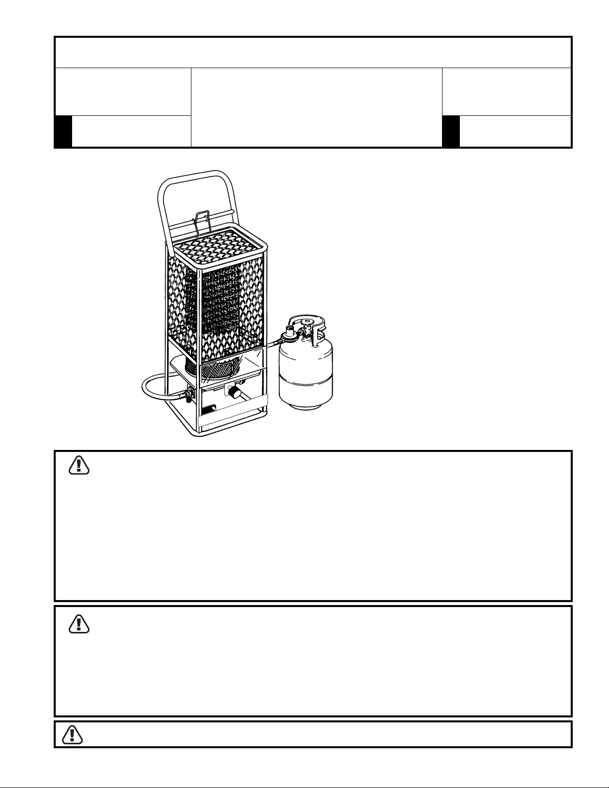
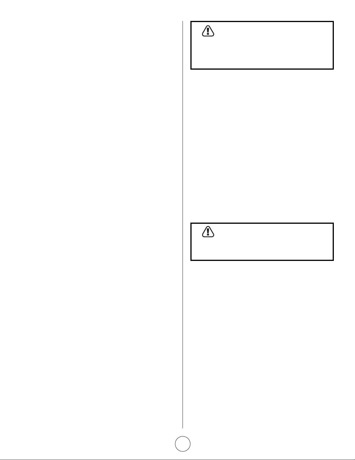
GAS-FIRED INFRA-RED
PORTABLE CONSTRUCTION HEATER
DO NOT LEAVE HEATER UNATTENDED OR IN OPERATION WHILE SLEEPING
HEATSTAR
MODEL
HS125NG, HS125LP
CYLINDER NOT INCLUDED
GENERAL HAZARD WARNING:
FAILURE TO COMPLY WITH THE PRECAUTIONS AND INSTRUCTIONS PROVIDED WITH THIS HEATER
CAN RESULT IN DEATH, SERIOUS BODILY INJURY AND PROPERTY LOSS OR DAMAGE FROM
HAZARDS OF FIRE, EXPLOSION, BURN, ASPHYXIATION, CARBON MONOXIDE POISONING, AND/OR
ELECTRICAL SHOCK.
ONLY PERSONS WHO CAN UNDERSTAND AND FOLLOW THE INSTRUCTIONS SHOULD USE OR
SERVICE THIS HEATER.
IF YOU NEED ASSISTANCE OR HEATER INFORMATION SUCH AS INSTRUCTION MANUALS, LABELS,
ETC., CONTACT THE MANUFACTURER.
WARNING:
FIRE, BURN, INHALATION AND EXPLOSION HAZARD. KEEP SOLID COMBUSTIBLES SUCH AS
BUILDING MATERIALS, PAPER OR CARDBOARD A SAFE DISTANCE AWAY FROM THE HEATER AS
RECOMMENDED BY THE INSTRUCTIONS. NEVER USE THE HEATER IN SPACES WHICH DO OR MAY
CONTAIN VOLATILE OR AIRBORNE COMBUSTIBLES OR PRODUCTS SUCH AS GASOLINE, SOLVENTS,
PAINT THINNER, DUST PARTICLES OR UNKNOWN CHEMICALS.
WARNING: NOT FOR HOME OR RECREATIONAL VEHICLE USE
04/04 Revision L1 #18666ENERCO GROUP, INC., 4560 W. 160TH ST., CLEVELAND, OHIO 44135 • 216-881-5500
Page 2
SPECIFICATIONS
MODEL NO. ................ MH125LP/HS125LP ..........HS125NG
GAS TYPE ....................................... LP-Gas ....... Natual Gas
MAX. INLET PRESSURE. ...........14 IN. W.C. ...... 14 IN. W.C.
MIN. INLET PRESSURE ............. 11 IN. W.C. ........ 7 IN. W.C.
MANIFOLD PRESSURE ........... 9.5 IN. W.C. ......... 6 IN.W.C.
WARNING
DO NOT EXCEED ½ psi (14” w.c.) GAS
PRESSURE TO THE GAS CONTROL VALVE.
VENTILATION
WARNING
THIS APPLIANCE IS UNVENTED AND MUST BE
USED ONLY IN A WELL VENTILATED AREA.
The flow of combustion and ventilation air must not be
obstructed. DO NOT use in a tightly enclosed area.
Any combustion process requires and consumes oxygen, and
may produce carbon monoxide. This heater must be operated
with adequate ventilation. Two openings directly to the outdoors
must be provided, one low and one high, preferably on opposite
sides of the area to be heated. Each of these openings must
provide at least three square inches of combustion air-intake area
and exhaust outlet area for every 1000 BTUs per hour of heater
input rate in order to complete the combustion/ventilation
process. Provide additional ventilation for any additional fuelburning appliances and/or additional occupants.
CLEARANCE (Minimum clearances to combustible materials)
Do not exceed the gas supply pressures shown on rating plates. The maximum inlet gas supply pressures and minimum inlet supply
pressures (for purposes of input adjustment) for LP-Gas and Natural gas are shown as follows:
MODEL NO. BTU/HR RATING NORMAL OPERATING CLEARANCES TO
TYPE GAS POSTION COMBUSTIBLES
NATURAL LP-GAS TOP SIDES BACK
MH125LP/
HS125LP 125,000* VERTICAL 48” 60” 60”
HS125NG 125,000 VERTICAL 48” 60” 60”
*Tank size and tank temperature can directly affect BTU output
CONTENTS
FOR YOUR SAFETY
Installation Instructions.................................................... 3
Location .......................................................................... 3
Piping .............................................................................. 3
Operating Instructions ..................................................... 4
Lighting and Shut Down .................................................. 4
Maintenance Instructions ................................................ 5
Replacement Parts List ..................................................... 6
Service and Parts Ordering Information ........................... 8
Do not use this heater in a space where
gasoline or other liquids having flammable
vapors are stored or used.
The heater is designed and approved for use as a construction
heater under ANSI Z83.7 / CGA 2.14 - 2000
We cannot anticipate every use which may be made of our
heaters. CHECK WITH YOUR LOCAL FIRE SAFETY AUTHORITY IF
YOU HAVE QUESTIONS ABOUT APPLICATIONS.
Other standards govern the use of fuel gases and heat producing
products in specific applications. Your local authority can advise
you about these.
This appliance is intended to be used primarily for the heating of
buildings under construction, alteration or repair.
THE STATE OF CALIFORNIA REQUIRES THE FOLLOWING WARNING:
WARNING
Combustion by-products produced when using this product contain
carbon monoxide, a chemical known to the State of California to
cause cancer and birth defects (or other reproductive harm).
Operating Instructions and Owner’s ManualEnerco Group, Inc. | Gas-Fired Infra-Red Portable Construction Heater
2
Page 3
INSTALLATION INSTRUCTIONS
GENERAL:
READ THESE INSTRUCTIONS CAREFULLY. Read and adhere
to these instructions. DO NOT allow anyone who has not
read these instructions to assemble, light, adjust or operate
this heater.
DO NOT attempt to operate the heater with any gas other
than that indicated on the heater nameplate.
For the U.S. and/or Canada, the installation of this appliance
must comply with local and/or Provincial codes or, in the
absence of these codes,
• With the (U.S.) National Fuel Gas Code, ANSI Z223.1 –
Latest Edition (for Natural and LP-Gas operation,
Models HS125NG, MH125LP, and HS125LP), and with
the (U.S) Standard for the Storage and Handling of
Liquefied Petroleum Gases, ANSI/NFPA 58 (for LP Gas
operation, Model MH125LP, HS125LP), or
• with the current (Canadian) CAN/CGA B149.1 AND
B149.2 INSTALLATION CODES.
This heater (including hose and regulator assembly if applicable)
must be inspected before each use and at least annually by a
qualified service person. If the hose for Model MH125LP/HS125LP
shows evidence of excessive abrasion or wear, or if the hose is
cut, it must be replaced prior to the heater being put into
operation. The replacement hose assembly shall be that specified
by the manufacturer. See the parts list.
LOCATION
The heater (and LP-Gas supply cylinder if applicable) must be
located on a hard, flat, level surface to minimize the risk of
accidental tipping. If an LP Gas supply cylinder is used (i.e. with
Model MH125LP/HS125LP), the cylinder should be adequately
restrained to prevent accidental tipping. DO NOT operate this
heater with the supply cylinder in any other than the
upright position.
This appliance must be installed only in locations where the
potential for physical damage to the appliance (i.e., due to
physical contact) is reduced to a minimum.
The installer must inform the owner/operator of this appliance
that precautions must be taken to protect the appliance from
physical damage.
This appliance produces radiant heat. Therefore, it must be
located at least six feet away from any LP-Gas container and
must not be directed toward any LP-Gas container within 20 feet.
The heater must be installed in a location such that it will not be
exposed directly to water spray, rain, and/or dripping water.
Use of this heater in a draft/windy area decreases its efficiency.
If possible, operate the unit in a draft free area.
PIPING
For Model MH125LP/HS125LP
(for use with LP-Gas)
This model may be connected to a self-contained LP-Gas
supply system using the hose and regulator assembly
supplied with the appliance, OR, it may be connected to a
permanently installed LP-Gas supply system.
If connected to a self-contained LP-Gas supply system, the
hose assembly must be inspected prior to each use of the
heater. If it is evident that there is excessive abrasion or
wear, or if the hose is cut, it must be replaced prior to the
heater being put into operation.
If connected to a self-contained LP-Gas supply system, the
cylinder must have no less than a minimum capacity of 20
pounds and no more than a maximum capacity of 100
pounds of LP-Gas. DO NOT connect this appliance to a
cylinder having less than a nominal 20 pounds capacity of
LP-Gas. DO NOT connect this appliance to more than one
(1) 100 pound cylinder.
WARNING
NEVER USE A FORK LIFT TRUCK TYPE
CYLINDER.
The connection of Model MH125LP/HS125LP to an LP-Gas
cylinder must be made in a well ventilated area using the
regulator and hose assembly supplied with the appliance. DO
NOT attempt to adjust this regulator. It has been preset at
the factory to provide safe and proper operation of the
appliance. Use a 7/8” open end wrench to connect the POL
fitting (supplied with the LP regulator) to the LP-Gas cylinder.
Turn the POL nut in a counter-clockwise direction (left hand
thread) until tight. DO NOT use pipe compound
on POL threads.
The heater must be located at least six feet away from any
LP-Gas cylinder and must not be directed toward any LP-Gas
cylinder within 20 feet. If more than one heater is used,
they and the supply cylinders must be separated by at least
20 feet.
The gas supply must be turned off at the LP-Gas supply
cylinder when the heater is not in use.
When the heater is to be stored indoors, the connection
between the LP-Gas supply cylinder and the heater must be
disconnected and the cylinder removed from the heater and
stored in accordance with Chapter 5 of the Standard for the
Storage and Handling of Liquefied Petroleum Gases. ANSI/
NFPA 58 (U.S.) OR CAN/CGA B149.2 (Canada).
If connected to a permanently installed LP-Gas supply
system, the system requires the use of a two-stage gas
regulator assembly which is normally provided by your LP
Gas dealer as part of the LP-Gas supply system. Consult
with your local LP Gas dealer for details concerning proper
equipment and installation.
Operating Instructions and Owner’s ManualEnerco Group, Inc. | Gas-Fired Infra-Red Portable Construction Heater
3
Page 4
For Model 125NG (for use with natural gas)
Piping must be clean and free from scale or burrs.
Install regulator supplied with heater. Connect with 1/2”
NPT nipple (not included) to Control Valve.
Connect the appliance to an appropriately designed and
installed fuel supply system. This system must include an
approved manual shut-off valve which is readily accessible
and is located within six (6) feet of the appliance.
Additionally, a sediment trap or drip leg must be located
upstream of this manual shut-off valve. Refer to the
appropriate (natural gas) installation code noted above. If a
flexible connector is used, it must be of an approved type.
Before attempting to ignite the appliance, all gas fittings and
connections must be thoroughly checked for gas leaks. Apply a
small amount of a mild soap and water solution to all fittings
and connections and observe for escaping bubbles. If any leaks
are detected, shut off the gas supply to the appliance
immediately. Wait a minimum of five minutes, repair the leak(s)
and retest for leakage. Dry all fittings and connections after leak
testing.
WARNING
NEVER USE A FLAME FOR GAS LEAK
TESTING.
OPERATING INSTRUCTIONS
WARNING
IF YOU DO NOT FOLLOW THESE
INSTRUCTIONS EXACTLY, A FIRE OR
EXPLOSION MAY RESULT CAUSING
PROPERTY DAMAGE, PERSONAL INJURY, OR
LOSS OF LIFE.
CAUTION
THIS APPLIANCE IS HOT DURING NORMAL
OPERATION, AVOID PHYSICAL CONTACT.
CAUTION
DO NOT PLACE CLOTHING OR OTHER
COMBUSTIBLE MATERIALS ON THIS
APPLIANCE.
DO NOT operate this heater if any part has been under
water. Call a qualified service technician to inspect the appliance
and to replace any part of the control system or gas control valve
which has been under water.
This appliance must be installed and operated only in locations
where the potential for physical damage to the appliance is
reduced to a minimum. The owner/operator of this appliance
must ensure that precautions are taken to protect the appliance
from physical damage.
LIGHTING AND SHUT DOWN
Lighting the Heater
1 Before attempting the light the heater, smell all around
the heater area for gas. Be sure to smell next to the
floor because LP Gas is heavier than air and will settle
on the floor. Turn on the gas supply to the appliance
and check all fittings and connections for gas leaks
using a mild soap and water solution. NEVER use a
match to check for gas leaks. Should a gas leak
occur, shut off the gas supply to the appliance
immediately. Wait a minimum of five minutes before
repairing the leak.
2 Use only the fuel intended for this appliance. Check the
appliance rating plate for the correct fuel information.
3 Turn the gas valve knob clockwise to the “OFF”
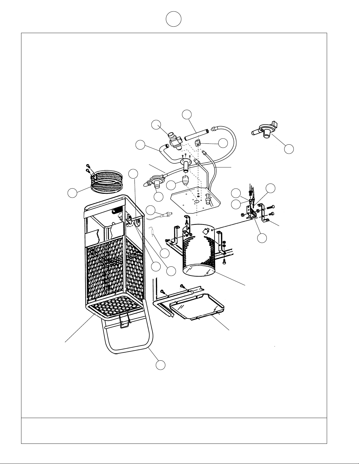
position. See Fig. 1 and Fig. 2 for location of appliance
parts.
4 Wait a sufficient length of time (at least five minutes)
to allow gas which may have accumulated in burner
compartment to escape.
5 Turn on the main gas supply.
6 Turn the gas valve knob counter-clockwise to the
“PILOT” position (see Fig. 1).
7a Depress and turn Control Knob counterclockwise to
“Pilot” position and hold for 1-2 minutes. This may take
longer to purge air from the supply hose depending on
the length of the hose being used.
Depress red spark ignition button to light pilot flame
(repeat until pilot lights) and continue to hold Control
Knob at “Pilot” positionfor 30-60 seconds to enable
Pilot Light Safety System.
Fully turn Control Knob to “Hi” position to light burner. or...
7b To light the pilot, move the lighting hole cover aside
(see Fig. 1) and place a lighted match into the hole.
Depress the gas valve knob and hold while lighting and
observing the pilot burner. Ensure that the pilot burner
ignites from the match. Allow the pilot to burn
approximately 30 seconds before releasing the gas
valve knob. If pilot does not remain lighted, repeat the
lighting operation allowing a longer period of time
before releasing the gas valve knob.
NOTE: In cases where long runs of gas supply lines have
been installed ahead of the appliance, it may be necessary
to bleed trapped air out of the supply lines before lighting
the pilot. New installations generally require bleed of supply
lines. Wait a minimum of five minutes after bleeding the
supply lines before attempting to light the heater.
Adjust pilot if necessary as noted under “Pilot Burner
Adjustment.”
Operating Instructions and Owner’s ManualEnerco Group, Inc. | Gas-Fired Infra-Red Portable Construction Heater
4
Page 5
8. Turn the gas valve knob counter-clockwise to the “ON”
position (see Fig. 1). The burner will light. DO NOT
operate the heater in any other than the full “ON”
position.
9. IMPORTANT: DO NOT attempt to adjust the main
burner input using the main gas supply valve, for
this may cause the pilot and thermocouple to shut
down the burner (Fig. 2).
Shut-down instructions:
To turn the heater OFF,
• For short periods of time, turn the main burner off by
rotating the gas valve knob clockwise to the “PILOT”
position.
• For extended periods of non use, turn the appliance
completely off by rotating the gas valve knob clockwise
to the “PILOT” position, depress the knob slightly, then
rotate the knob fully clockwise to the “OFF” position.
(Note: For Model 120L, also turn off the gas supply
cylinder.)
Pilot burner adjustment:
1. Remove the pilot adjustment cap. The pilot adjustment
cap is a slotted screw located in front of the “Pilot”
designation stamped on top of valve body just below
the gas valve knob.
2. Adjust the pilot key to provide properly sized flame.
Rotate the key “clockwise” to decrease or “counterclockwise” to increase flame.
3. Replace the pilot adjustment cap.
DANGER
DO NOT ATTEMPT TO CLEAN THE HEATER
WHILE IT IS OPERATING OR WHILE IT IS STILL
HOT.
Turn the heater off and wait until it has completely cooled (at
least 20minutes) before cleaning.
Clean the outside of the heater using a damp cloth. DO NOT
clean the heater by spraying water on it. Wipe the outside of the
heater off with a dry cloth after cleaning.
Clean the inside of the heater using compressed air. Blow air
back and forth along all inside surfaces until all dust has been
dislodged.
Clean the orifice of each burner with a #69 drill bit (for LP-Gas).
Clean the orifice manually (by hand) – DO NOT use power drill.
Clean the thermocouple lead.
DO NOT operate this heater if any part has been under
water. Call a qualified service person to inspect the appliance
and to replace any part of the control system or gas control valve
which has been under water.
This heater must be inspected at least annually by a qualified
service person.
WARNING
Do not exceed ½ PSI gas pressure to
appliance gas control valve.
MAINTENANCE INSTRUCTIONS
This heater (including hose and regulator assembly if applicable)
must be inspected before each use. If the hose for the Model
120L shows evidence of excessive abrasion or wear, or if the hose
is cut, it must be replaced prior to the heater being put into
operation. The replacement hose assembly shall be that specified
by the manufacturer. See the parts list.
The appliance area must be kept free and clear of combustible
materials, gasoline and other flammable vapors and liquids at all
times.
The flow of combustion and ventilation air must not be
obstructed.
Cleaning the heater:
Periodically, the heater must be cleaned of all dirt and dust
particles.
Operating Instructions and Owner’s ManualEnerco Group, Inc. | Gas-Fired Infra-Red Portable Construction Heater
5
Page 6

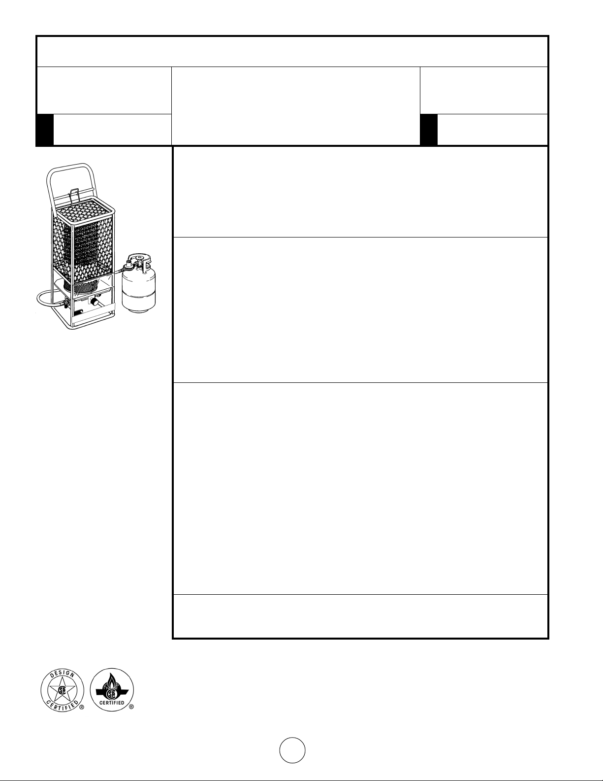
REPLACEMENT PARTS LIST FOR
MODELS HS125NG / MH125LP / HS125LP
SEE BACK PAGE FOR PARTS ORDERING INFORMATION
REF. # ITEM # DESCRIPTION
1 ...................... 00332 ............ Manual Control Valve
2 ...................... 04466 ........... Filter/Diffuser
3 ...................... 05363 ............ Orifice Pilot(MH125LP/HS125LP)
4 ...................... 09352 ............ Thermocouple
5 ...................... 11357 ............. Pilot Burner
6 ...................... 11663 ............ Regulator (MH125LP/HS125LP)
Figure 1
Figure 2
7 ...................... 11666 ............ Regulator (HS125NG)
8 ...................... 05374 ............ Orifice Pilot (HS125NG)
9 ...................... CR805 ........... Ignitor
10 ..................... CR835 ........... Piezo
11 ..................... CR820 ........... Axle
12 ..................... CR815 ............ Axle Brackets
13 ..................... CR725 ........... Handle
14 ..................... CR810 ........... Wheel
15 ..................... M9005 .......... Valve Supply Tube
16 ..................... M9010 ........... Valve Supply Tube Clamp
17 ..................... M9015 ........... Burner Manifold
18 ..................... M9020 .......... Burner
Operating Instructions and Owner’s ManualEnerco Group, Inc. | Gas-Fired Infra-Red Portable Construction Heater
6
Page 7

Combustion Chamber
GAS-FIRED INFRA-RED PORTABLE CONSTRUCTION HEATER
MODELS HS125NG / MH125LP / HS125LP
13
Frame Assembly
Top Plate
12
11
Mounting Bracket
7
5
4
Pilot Supply Tube
9
10
3
6
8
2
18
14
Propane Hose
16
15
17
1
Operating Instructions and Owner’s ManualEnerco Group, Inc. | Gas-Fired Infra-Red Portable Construction Heater
7
Page 8
OPERATING INSTRUCTIONS AND OWNER’S MANUAL
MR. HEATER
MODEL
MH125LP
READ INSTRUCTIONS CAREFULLY: Read and
follow all instructions. Place instructions in a
safe place for future reference. Do not allow
anyone who has not read these instructions to
HEATSTAR
MODEL
HS125NG, HS125LP
assemble, light, adjust or operate the heater.
WARNING:
USE ONLY MANUFACTURER’S REPLACEMENT PARTS. USE OF ANY OTHER PARTS
COULD CAUSE INJURY OR DEATH. REPLACEMENT PARTS ARE ONLY AVAILABLE
DIRECT FROM THE FACTORY AND MUST BE INSTALLED BY A QUALIFIED SERVICE
AGENCY.
PARTS ORDERING INFORMATION:
PURCHASING: Accessories may be purchased at any Mr. Heater or HeatStar local
dealer or direct from the factory
FOR INFORMATION REGARDING SERVICE
Please call Toll-Free 800-251-0001
www.enerco-mrheater.com
Our office hours are 8:30 AM – 5:00 PM, EST, Monday through Friday.
Please include the model number, date of purchase, and description of problem in
all communication.
WARRANTY
Gas Fired Infra Red Portable Construction Heater HS125NG, MH125LP, & HS125LP
Enerco Group, Inc. warrants that Infra Red Heaters manufactured and sold will be free from
defects in material and workmanship.
Parts assemblies controls, etc. furnished by Enerco Group, Inc. will carry a one (1) year
warranty on the applicable warranties of the suppliers.
The sole responsibility of Enerco Group, Inc. under this warranty shall be to replace or repair
any part for which a written claim is made to Enerco Group, Inc. within the time limit of
this warranty which is returned upon request to Enerco Group, Inc. – F.O.B. Cleveland Ohio
– or F.O.B. an Enerco Group, Inc. authorized service facility and which is proved to be
defective upon inspection by Enerco Technical Products.
This warranty shall not apply to any part or product which has been subjected to misuse or
neglect, damaged by accident, or rendered defective by reason of improper installation.
THIS WARRANTY IS IN LIEU OF ANY AND ALL OTHER WARRANTIES, EXPRESSED OR
IMPLIED, and of any other responsibility of Enerco Technical Products for parts or products
sold by Enerco Technical Products, including consequential or special damages.
Enerco Group, Inc. reserves the right to make changes at any time, without notice or
obligation, in colors, specifications, accessories, materials and models.
ANSI Z83.7/CGA 2.14-2000
ENERCO GROUP, INC., 4560 W. 160TH ST., CLEVELAND, OHIO 44135 • 216-881-5500
Enerco and Mr. Heater are registered trademarks of Enerco Group, Inc.
© 2003, Enerco/Mr. Heater. All rights reserved
Operating Instructions and Owner’s ManualEnerco Group, Inc. | Gas-Fired Infra-Red Portable Construction Heater
8
Page 9

8
© 2003, Enerco Group, Inc. Tous droits réservés
Enerco et Mr. Heater sont des marques déposées d'Enerco Group, Inc.
Enerco Group, Inc., 4560 W. 160TH ST., CLEVELAND, OHIO 44135 o (216) 881-5500
obligation, concernant les couleurs, les spécifications, les accessoires, les matériaux et les modèles.
Enerco Group, Inc. se réserve le droit d'apporter des modifications à tout moment, sans préavis ou
vendus par Enerco Group, Inc.,, notamment les dommages indirects ou spéciaux.
IMPLICITE, ainsi que toute autre responsabilité d'ENERCO concernant les pièces ou les produits
installation. LA PRÉSENTE GARANTIE REMPLACE TOUTE AUTRE GARANTIE, EXPLICITE OU
manipulation ou de négligence, a été endommagé à la suite d'un accident ou d'une mauvaise
La présente garantie ne s'applique pas si une pièce ou un produit a fait l'objet d'une mauvaise
service autorisée par Enerco Group, Inc.,.
Enerco Group, Inc., -par franco à bord à Cleveland, Ohio - ou franco à bord à toute installation de
dans la période de temps stipulée par la garantie, laquelle doit être retournée sur demande à
l'attention d'Enerco Group, Inc. et après qu'Enerco Group, Inc. a confirmé sa défectuosité et ce,
remplacer ou de réparer toute pièce défectueuse pour laquelle une réclamation a été écrite à
L'unique responsabilité d'Enerco Group, Inc. conformément à la présente garantie est de
par une garantie d'un (1) an sur les garanties applicables des fournisseurs.
Les ensembles de pièces, les pièces de contrôle, etc. fournis par Enerco Group, Inc., sont couverts
défaut lié aux pièces ou à la main d'oeuvre.
Enerco Group, Inc., garantit que ses appareils de chauffage à infrarouge ne comportent aucun
Appareil de chauffage portatif à infrarouge et au gaz HS125NG, MH125LP et HS125LP
GARANTIE
Enerco Group, Inc. | Appareil de chauffage portatif à infrarouge et au gaz Manuel de l'utilisateur et instructions d'utilisation
ANSI Z83.7/CGA 2.14-2000
HS125NG, HS125LP
No de modèles
HEATSTAR
lorsque vous communiquez avec notre service.
Veuillez fournir le numéro du modèle, la date d'achat et la description du problème
Nos heures d'ouverture sont de 8 h 30 à 17 h, heure de l'Est, du lundi au vendredi
www.mrheater.com
Veuillez composer le numéro sans frais suivant : (800) 251-0001
INFORMATION SUR LE SERVICE
ou Enerco, ou directement de l'usine.
ACHAT : des accessoires peuvent être achetés auprès de votre détaillant local Mr. Heater
COMMANDE DE PIÈCES
DOIVENT ÊTRE INSTALLÉES PAR UN TECHNICIEN QUALIFIÉ.
REMPLACEMENT SONT UNIQUEMENT DISPONIBLES AUPRÈS DE L'USINE ET
D'AUTRES PIÈCES PEUT CAUSER DES BLESSURES OU LA MORT. LES PIÈCES DE
UTILISEZ SEULEMENT LES PIÈCES DE REMPLACEMENT DU FABRICANT. L'UTILISATION
MISE EN GARDE
l'appareil de chauffage.
mettre en marche, de régler ou de faire fonctionner
n'a pas lu le manuel de l'utilisateur tenter de monter, de
fins de référence ultérieure. NE LAISSEZ PERSONNE qui
Rangez le manuel de l'utilisateur dans un endroit sûr aux
REMARQUE : lisez et suivez les instructions d'utilisation.
MH125LP
No de modèles
MR. HEATER
MANUEL DE L'UTILISATEUR ET INSTRUCTIONS D'UTILISATION
Page 10
7
Enerco Group, Inc. | Appareil de chauffage portatif à infrarouge et au gaz Manuel de l'utilisateur et instructions d'utilisation
15
1
17
Tuyau pour gaz propane
16
7
de la veilleuse
Tube d'alimentation
14
18
2
6
8
4
3
10
fixation
Support de
5
9
11
12
Chambre de combustion
Plateau supérieur
Structure
13
N
MODÈLES HS125NG / MH125LP / HS125LP
O
Enerco / Mr. Heater
APPAREIL DE CHAUFFAGE PORTATIF À INFRAROUGE ET AU GAZ
Page 11
6
18 ..................... M9020 .......... Burner
Enerco Group, Inc. | Appareil de chauffage portatif à infrarouge et au gaz Manuel de l'utilisateur et instructions d'utilisation
17 ..................... M9015 ........... Burner Manifold
16 ..................... M9010 ........... Valve Supply Tube Clamp
15 ..................... M9005 .......... Valve Supply Tube
14 ..................... CR810 ........... Roue
13 ..................... CR725 ........... Poignée
12 ..................... CR815............Tige de l'essieu
11 ..................... CR820 ........... Essieu
10 ..................... CR835 ........... Piezo
9 ...................... CR805 ........... Allumeur
8 ...................... 05374 ............ Orifice de la veilleuse (HS125NG)
7 ...................... 11666 ............Régulateur (HS125NG)
6 ...................... 11695 ............. Régulateur (MH125LP/HS125LP)
5 ...................... 11357 ............. Brûleur de la veilleuse
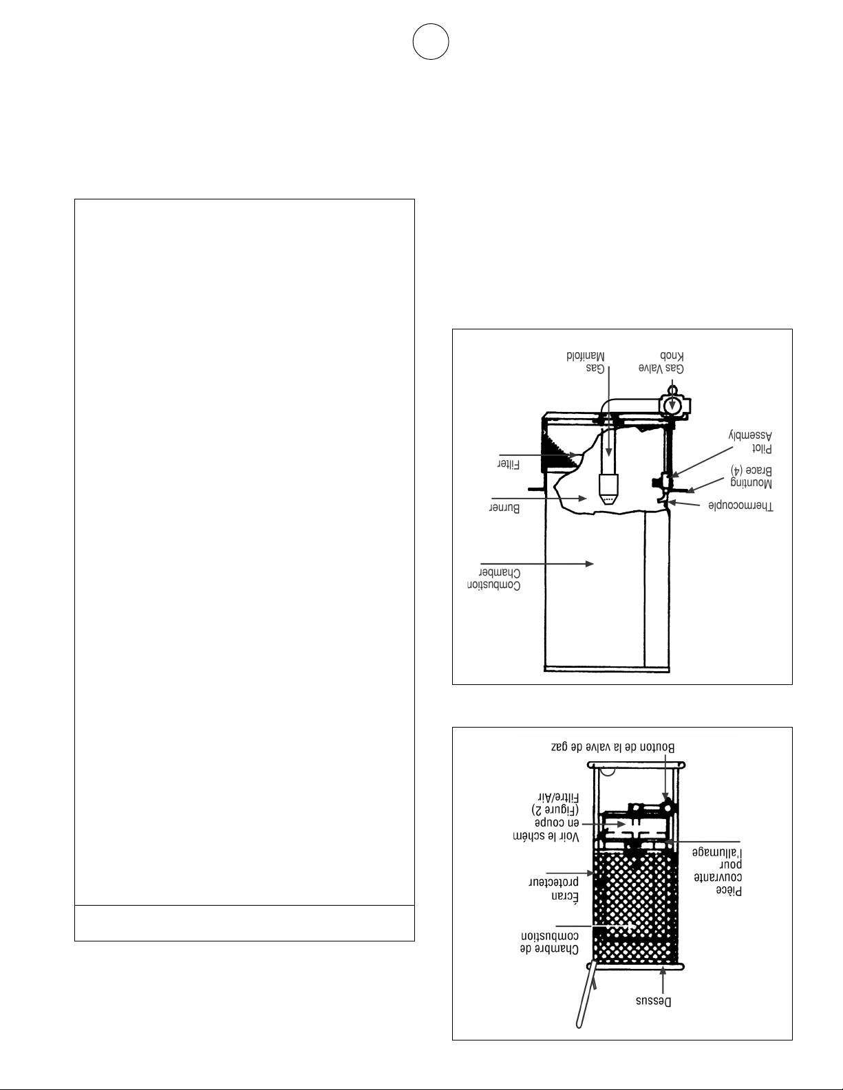
Figure 2
Figure 1
4 ...................... 09352 ............ Thermocouple
(MH125LP/HS125LP)
3 ...................... 05363 ............ Orifice de la veilleuse
2 ...................... 04466 ........... Filtre/Diffuseur
1 ...................... 00332 ............ Valve de contrôle manuelle
N
RÉF. No ARTICLE DESCRIPTION
o
INFORMATIONS SUR LA COMMANDE DE PIÈCES
VOIR LA DERNIÈRE PAGE POUR OBTENIR DES
MODÈLES HS125NG / MH125LP / HS125LP
o
LISTE DES PIÈCES DE REMPLACEMENT N
Page 12
5
valve de contrôle du gaz de l'appareil.
N'excédez pas ½ PSI de pression de gaz à la
MISE EN GARDE
année par une personne qualifiée.
L'appareil de chauffage doit être inspecté au moins une fois par
de l'eau.
système de contrôle ou de la valve ayant été en contact avec
procéder à une vérification de l'appareil et remplacer toute pièce du
contact avec de l'eau. Faites appel à un technicien qualifié pour
N'UTILISEZ PAS l'appareil si l'un de ses composants a été en
Nettoyez le fil du thermocouple.
main - N'UTILISEZ PAS de perceuse électrique.
n
69 (pour gaz propane liquéfié). Nettoyez l'orifice à la
o
Nettoyez l'orifice de chaque brûleur à l'aide d'une mèche
que la saleté soit délogée.
Soufflez de l'air sur toutes les surfaces intérieures jusqu'à ce
Nettoyez l'intérieur de l'appareil en utilisant de l'air comprimé.
Enerco Group, Inc. | Appareil de chauffage portatif à infrarouge et au gaz Manuel de l'utilisateur et instructions d'utilisation
d'enlever toute particule de poussière et de saleté.
L'appareil de chauffage doit être nettoyé régulièrement afin
Nettoyage
ralentis.
La circulation d'air et le flux de combustion ne doivent pas être
combustibles, d'essence ou de vapeurs ou de liquides inflammables.
L'espace environnant de l'appareil doit toujours être dépourvu de
de remplacement.
doit avoir été approuvée par le fabricant. Voir la liste des pièces
l'appareil de chauffage en marche. La tuyauterie de remplacement
d'usure excessive, ou s'il est coupé, remplacez-le avant de mettre
chaque utilisation. Si le tuyau du modèle 120L montre des signes
l'ensemble de régulation, le cas échéant) doit être inspecté avant
Le présent appareil de chauffage (y compris la tuyauterie et
ENTRETIEN
3. Replacez le capuchon de réglage de la veilleuse.
l'augmenter.
pour diminuer la flamme, ou en sens anti-horaire pour
de taille appropriée. Faites tourner la clé en sens horaire
2. Réglez la clé de la veilleuse pour obtenir une flamme
de gaz.
du corps de la valve, juste sous le bouton de la valve
face de la désignation « Pilot » imprimée sur le dessus
capuchon de réglage est une vis fendue située en
1. Enlevez le capuchon de réglage de la veilleuse. Le
Réglage de la veilleuse
pas de fermer la bonbonne de gaz.)
« OFF ». (Remarque : pour le modèle 120L, n'oubliez
faites-le tourner en sens horaire jusqu'à la position
« PILOT », appuyez légèrement sur le bouton, puis
de la valve de gaz en sens horaire jusqu'à la position
complètement l'appareil en faisant tourner le bouton
• Pour de longues périodes d'inutilisation, fermez
horaire jusqu'à la position « PILOT ».
faisant tourner le bouton de la valve de gaz en sens
• Pour de courtes durées, fermez le brûleur principal en
Pour éteindre l'appareil de chauffage
DANGER
Essuyez ensuite l'extérieur avec un chiffon sec.
NETTOYEZ PAS l'appareil de chauffage en y vaporisant de l'eau.
Nettoyez l'extérieur de l'appareil à l'aide d'un chiffon humide. NE
minutes) avant de le nettoyer.
Éteignez l'appareil et laissez-le refroidir complètement (au moins 20
EN MARCHE OU ENCORE CHAUD.
figure 2).
thermocouple pourraient fermer le brûleur (Voir
d'alimentation principale, car la veilleuse et le
en gaz du brûleur principal à l'aide de la valve
DE CHAUFFAGE LORSQUE CELUI-CI EST
NE TENTEZ PAS DE NETTOYER L'APPAREIL
le brûleur dans une position autre que " ON ".
Le brûleur s'allumera. NE FAITES PAS fonctionner
anti-horaire jusqu'à la position " ON " (voir figure 1).
Arrêt de l'appareil
9. IMPORTANT : N'ESSAYEZ PAS de régler l'admission
8. Faites tourner le bouton de la valve de gaz en sens
Page 13

4
Enerco Group, Inc. | Appareil de chauffage portatif à infrarouge et au gaz Manuel de l'utilisateur et instructions d'utilisation
la veilleuse ».
Réglez la veilleuse au besoin, tel que décrit sous « Réglage de
5 minutes avant d'essayer d'allumer le brûleur.
d'alimentation, attendez au moins
des nouvelles installations. Après voir enlevé l'air des conduites
veilleuse. C'est souvent le cas pour les conduites d'alimentation
devrez peut-être enlever l'air de ces conduites avant d'allumer la
gaz ont été installées en avant de l'appareil de chauffage, vous
REMARQUE : si de longues conduites d'alimentation en
longtemps avant de relâcher le bouton de la valve de gaz.
répétez la démarche d'allumage et attendez un peu plus
de la valve de gaz. Si la veilleuse ne reste pas allumée,
pendant environ 30 secondes avant de relâcher le bouton
l'allumette allume le brûleur. Laissez la veilleuse brûler
observant le bouton de la veilleuse. Assurez-vous que
et maintenez-le enfoncé pendant l'allumage tout en
dans le trou. Appuyez sur le bouton de la valve de gaz
d'allumage (voir figure 1) et placez une allumette allumée
7b Pour allumer la veilleuse, déplacez le couvercle du trou
« Hi » pour allumer le brûleur. ou...
Faites tourner le bouton de contrôle jusqu'à la position
la veilleuse.
30-60 secondes afin d'activer le système de sécurité de
de contrôle enfoncé en position« Pilot » pendant encore
veilleuse s'allume) et continuez de maintenir le bouton
la flamme de la veilleuse (répétez jusqu'à ce que la
Appuyez sur le bouton d'allumage rouge pour allumer
utilisez un long boyau d'alimentation.
d'évacuation d'air peut prendre plus de temps si vous
enfoncé pendant 1 ou 2 minutes. Le processus
sens anti-horaire jusqu'à la position « Pilot ». Maintenez-le
7a Appuyez sur le bouton de contrôle et faites-le tourner en
horaire jusqu'à la position « PILOT » (voir figure 1).
6 Faites tourner le bouton de la valve de gaz en sens anti5 Ouvrez l'alimentation de gaz principale.
brûleur.
gaz qui s'est peut-être accumulé dans la chambre du
4 Attendez au moins 5 minutes pour laisser s'échapper le
connaître l'emplacement des pièces de l'appareil.
jusqu'à la position « OFF ». Voir les figures 1 et 2 pour
3 Faites tourner le bouton de la valve de gaz en sens horaire
de combustible à utiliser.
signalétique pour obtenir des informations sur le type
le présent appareil de chauffage. Consultez la plaque
2 Utilisez seulement le type de combustible prévu pour
fuite.
Attendez au moins 5 minutes avant de colmater la
immédiatement l'alimentation en gaz à l'appareil.
détecter une fuite. En cas de fuite, couper
savonneuse. N'UTILISEZ JAMAIS une flamme nue pour
les joints pour détecter toute fuite de gaz à l'aide d'eau
niveau du sol. Alimentez l'appareil en gaz et inspectez
est plus lourd que l'air, il est important de sentir au
d'odeur de gaz. Étant donné que le gaz propane liquéfié
1 Avant d'allumer l'appareil, assurez-vous qu'il n'y a pas
Allumage de l'appareil
ALLUMAGE ET ARRÊT
d'éventuels dommages physiques.
précautions nécessaires sont prises afin de protéger l'appareil contre
réduit au minimum. Le propriétaire/utilisateur doit s'assurer que les
des endroits où le potentiel de dommages physiques à l'appareil est
Le présent appareil de chauffage doit être installé seulement dans
système de contrôle ou de la valve ayant été en contact avec de l'eau.
procéder à une vérification de l'appareil et remplacer toute pièce du
contact avec de l'eau. Faites appel à un technicien qualifié pour
N'UTILISEZ PAS l'appareil si l'un de ses composants a été en
CHAUFFAGE.
MATÉRIAU COMBUSTIBLE SUR L'APPAREIL DE
NE DÉPOSEZ PAS DE VÊTEMENT OU AUTRE
AVERTISSEMENT
CONTACT PHYSIQUE.
EN COURS D'UTILISATION. ÉVITEZ TOUT
LE PRÉSENT APPAREIL DEVIENT TRÈS CHAUD
AVERTISSEMENT
BLESSURES CORPORELLES OU LA MORT.
CAUSER DES DOMMAGES DE BIENS, DES
OU UNE EXPLOSION PEUT S'ENSUIVRE ET
INSTRUCTIONS À LA LETTRE, UN INCENDIE
SI VOUS NE RESPECTEZ PAS LES
MISE EN GARDE
INSTRUCTIONS D'UTILISATION
COLMATÉE.
PROCÉDER À LA VÉRIFICATION D'UNE FUITE
N'UTILISEZ JAMAIS UNE FLAMME NUE POUR
MISE EN GARDE
vérification.
et faites une autre vérification. Faites sécher les joints après la
l'alimentation en gaz. Attendez au moins 5 minutes, réparez la fuite
en présence de fuite. Dans un tel cas, couper immédiatement
d'eau savonneuse sur tous les joints; des bulles se formeront
éventuelles. Pour détecter des fuites, appliquez une petite quantité
fixation et les joints sont bien installés afin de prévenir des fuites
Avant d'allumer l'appareil, veuillez vous assurer que les pièces de
approuvé.
susmentionné. Veuillez n'utiliser qu'un connecteur flexible
vous référer au code d'installation approprié (gaz naturel)
être installé en amont de la valve d'arrêt manuelle. Veuillez
réservoir de décantation ou un collecteur de condensats doit
située à un maximum de 6 pieds de l'appareil. De plus, un
d'arrêt manuelle approuvée, laquelle doit être accessible et
et installé de façon adéquate. Ce système doit inclure une valve
Branchez l'appareil à un système d'alimentation en gaz conçu
NPT de 1/2 po (non fourni).
Branchez-le à la valve de contrôle à l'aide d'un raccord fileté
Installez le régulateur fourni avec l'appareil de chauffage.
bavure de mortier ou présenter des dépôts calcaires.
La tuyauterie doit être rester propre et ne doit pas être salie de
Modèle 200N (au gaz naturel)
Page 14

3
renseigner auprès de votre fournisseur de gaz local.
d'installation et l'équipement appropriés, veuillez vous
obtenir de plus amples informations sur les instructions
fournisseur de gaz avec le système d'alimentation de gaz. Pour
régulation à deux phases habituellement fourni par votre
permanente, le système requiert l'utilisation d'un ensemble de
Si branché à un système d'alimentation de gaz installé de façon
(É.-U.) OU CAN/CGA B149.2 (Canada).
Handling of Liquefied Petroleum Gases) ANSI/NFPA 58
manipulation des gaz liquéfiés (Standard for the Storage and
la façon indiquée au chapitre 5 de la norme d'entreposage et de
bonbonne enlevée de l'appareil de chauffage et entreposée de
entre la bonbonne de gaz et l'appareil doit être débranché, et la
Si l'appareil de chauffage est entreposé à l'intérieur, le tuyau
de gaz.
en gaz doit être coupée à la source, c'est-à-dire à la bonbonne
Lorsque l'appareil de chauffage n'est pas utilisé, l'alimentation
doivent être séparés par une distance d'au moins 20 pieds.
chauffage sont utilisés, ces derniers ainsi que les bonbonnes
bonbonne de gaz à moins de 20 pieds. Si plusieurs appareils de
d'une bonbonne de gaz et ne doit pas faire face à une
L'appareil de chauffage doit être placé à au moins six pieds
pour joints de tuyaux sur le filetage de gauche.
horaire (filetage à gauche). N'UTILISEZ PAS de mastic
gaz) à la bonbonne de gaz. Vissez l'écrou de gauche en sens antibrancher la pièce de fixation de gauche (fournie avec le régulateur à
sécuritaire de l'appareil. Utilisez une clé à fourche 7/8 po pour
été réglé en usine afin d'assurer un fonctionnement adéquat et
l'appareil. N'ESSAYEZ PAS de régler ce régulateur. Celui-ci a
l'aide de la tuyauterie et de l'ensemble de régulation fournis avec
gaz propane liquéfié doit être effectué dans un endroit bien aéré à
Le branchement du modèle MH125LP/HS125LP à une bonbonne de
TYPE CHARIOT ÉLÉVATEUR À FOURCHE
N'UTILISEZ JAMAIS UNE BONBONNE DE
MISE EN GARDE
ayant une capacité de 100 livres.
20 livres. NE BRANCHEZ PAS l'appareil à plus d'une bonbonne
ayant une capacité de gaz propane liquéfié nominale de
respectivement. NE BRANCHEZ PAS l'appareil à une bonbonne
propane liquéfié minimale et maximale de 20 et 100 livres
propane liquéfié, la bonbonne doit avoir une capacité de gaz
Si branchée à un système d'alimentation autonome de gaz
en marche.
est coupé, remplacez-le avant de mettre l'appareil de chauffage
utilisation. Si le tuyau montre des signes d'usure excessive, ou s'il
propane liquéfié, la tuyauterie doit être examinée avant chaque
Si branchée à un système d'alimentation autonome de gaz
installé de façon permanente.
branché à un système d'alimentation de gaz propane liquéfié
l'ensemble de régulation fournis avec l'appareil OU peut être
autonome de gaz propane liquéfié à l'aide du tuyau et de
Ce modèle peut être branché à un système d'alimentation
(pour utilisation avec du gaz propane liquéfié)
Modèle MH125LP/HS125LP
TUYAUTERIE
Enerco Group, Inc. | Appareil de chauffage portatif à infrarouge et au gaz Manuel de l'utilisateur et instructions d'utilisation
endroit sans courant d'air.
venteux. Dans la mesure du possible, installez l'appareil dans un
L'efficacité de l'appareil sera réduite si vous l'utilisez dans un endroit
ou à la pluie.
L'appareil ne doit pas être exposé directement à l'eau pulvérisée
ne doit pas faire face à une bonbonne de gaz à moins de 20 pieds.
doit donc être placé à au moins six pieds d'une bonbonne de gaz et
Le présent appareil de chauffage produit de la chaleur rayonnante. Il
d'éventuels dommages physiques.
des précautions à prendre pour protéger l'appareil contre
L'installateur doit informer le propriétaire/l'utilisateur de l'appareil
(p. ex. causés par un contact physique) est réduit au minimum.
des endroits où le potentiel de dommages physiques à l'appareil
Le présent appareil de chauffage doit être installé seulement dans
bonbonne de gaz en une position autre que verticale.
ne tombe. N'UTILISEZ PAS l'appareil de chauffage avec la
être installée de façon sécuritaire afin d'empêcher qu'elle
propane est utilisée (avec le modèle MH125LP/HS125LP), celle-ci doit
afin de réduire les risques de basculement. Si une bonbonne de gaz
échéant) doit être placé sur une surface dure, plane et au niveau
L'appareil de chauffage (et la bonbonne de gaz propane, le cas
EMPLACEMENT
des pièces de remplacement.
remplacement doit avoir été approuvée par le fabricant. Voir la liste
de mettre l'appareil de chauffage en marche. La tuyauterie de
signes d'usure excessive, ou s'il est coupé, remplacez-le avant
qualifiée. Si le tuyau du modèle MH125LP/HS125LP montre des
utilisation et au moins une fois par année par une personne
régulation, le cas échéant) doit être inspecté avant chaque
L'appareil de chauffage (y compris le tuyau et l'ensemble de
ET B149.2
• aux CODES D'INSTALLATION (Canada) CAN/CGA B149.1
du gaz propane liquéfié, modèle MH125LP, HS125LP), ou
Petroleum Gases), ANSI/NFPA 58 (pour la manipulation
(Standard for the Storage and Handling of Liquefied
sur l'entreposage et la manipulation de gaz liquéfiés
modèles HS125NG, MH125LP et HS125LP), et à la norme
manipulation du gaz naturel et du gaz propane liquéfiés,
Fuel Gas Code), ANSI Z223.1 - dernière édition (pour la
• au code national (É.-U.) de gaz inflammables (National
dans l'absence de tels codes,
doit être conforme aux codes locaux et/ou provinciaux ou,
Pour les É.-U. et le Canada, l'installation du présent appareil
sur la plaque signalétique.
chauffage avec un type de gaz autre que celui indiqué
N'ESSAYEZ JAMAIS de faire fonctionner l'appareil de
de régler ou de faire fonctionner l'appareil de chauffage.
tenter de monter, de mettre en marche,
NE LAISSEZ PERSONNE qui n'a pas lu le manuel de l'utilisateur
SUIVANTES ET LES APPLIQUER
VEUILLEZ LIRE ATTENTIVEMENT LES INSTRUCTIONS
GÉNÉRAL :
INSTRUCTIONS D'INSTALLATION
Page 15

2
congénitales (ou autres anomalies liées au système reproducteur).
selon l'État de Californie, peut être cause de cancer et de malformations
produit dégage du monoxyde de carbone, un produit chimique qui,
La combustion de sous-produits générée durant l'utilisation du présent
MISE EN GARDE
MISE EN GARDE SPÉCIALE POUR L'ÉTAT DE CALIFORNIE
chauffer les structures en construction ou en réparation.
Le présent appareil de chauffage est principalement destiné à
à ce sujet.
votre commission locale pour obtenir de plus amples informations
de gaz combustibles et d'appareils de chauffage. Demandez à
Pour certaines applications, d'autres normes régissent l'utilisation
COMMUNIQUER AVEC VOTRE SERVICE DES INCENDIES LOCAL.
QUANT AUX DIFFÉRENTES UTILISATIONS POSSIBLES, VEUILLEZ
de nos appareils de chauffage. SI VOUS AVEZ DES QUESTIONS
Nous ne pouvons pas prévoir toutes les possibilités d'utilisation
construction, conformément à la norme ANSI Z83.7 / CGA 2.14 - 2000
Cet appareil de chauffage est destiné à être utilisé sur les chantiers de
entreposés ou utilisés.
dégagent des vapeurs inflammables sont
endroit où de l'essence ou autres liquides qui
N'utilisez pas l'appareil de chauffage dans un
MESURES DE SÉCURITÉ
Enerco Group, Inc. | Appareil de chauffage portatif à infrarouge et au gaz Manuel de l'utilisateur et instructions d'utilisation
Service à la clientèle et commande de pièces................... 8
Liste des pièces de remplacement .................................... 6
Entretien.......................................................................... 5
Allumage et arrêt ............................................................ 4
Instructions d'utilisation ................................................... 4
Tuyauterie ........................................................................ 3
Emplacement................................................................... 3
Instructions d'installation ................................................. 3
CONTENU
se trouvent dans la même pièce que l'appareil de chauffage.
si des appareils à combustible ou des personnes supplémentaires
combustion/ventilation. Veuillez assurer une meilleure ventilation
par l'appareil de chauffage afin de compléter le processus de
prise et de sortie d'air pour chaque 1 000 BTU/heure consommé
de ces ouvertures doit permettre au moins 3 pouces carrés de
haute, de préférence sur des côtés opposés de la pièce. Chacune
donnent directement vers l'extérieur, soit une basse et une
l'appareil est mis en marche doit comporter deux ouvertures qui
être utilisé en présence d'une aération adéquate. L'endroit où
produire du monoxyde de carbone. L'appareil de chauffage doit
Tout processus de combustion requiert de l'oxygène et peut
ralentis. N'UTILISEZ PAS l'appareil dans un endroit fermé.
La circulation d'air et le flux de combustion ne doivent pas être
ENDROIT BIEN AÉRÉ.
DOIT ÊTRE UTILISÉ SEULEMENT DANS UN
LE PRÉSENT APPAREIL N'EST PAS VENTILÉ ET
MISE EN GARDE
VENTILATION
*La capacité et la température du réservoir peuvent influer directement sur la production de BTU
HS125NG 125 000 VERTICALE 48 po 60 po 60 po
HS125LP 125 000* VERTICALE 48 po 60 po 60 po
MH125LP/
NATUREL GAZ PROPANE HAUT CÔTÉS ARRIÈRE
MODÈLE TYPE DE GAZ DE FONCTIONNEMENT AUTOUR DES COMBUSTIBLES
NO DE TAUX BTU/HEURE POSITION NORMALE DISTANCES DE DÉGAGEMENT
(pour le réglage de l'admission) pour le gaz propane liquéfié et le gaz naturel sont les suivantes :
N'excédez pas les pressions d'admission de gaz indiquées sur les plaques signalétiques. Les pressions d'admission maximale et minimale
DÉGAGEMENT (Distances de dégagement autour de matériaux combustibles)
PRESSION À LA VALVE D'ADMISSION DU GAZ.
N'EXCÉDEZ PAS ½ PSI (14 POUCES D'EAU) DE
MISE EN GARDE
PRESSION D'ADMISSION ..... 9.5 PO D'EAU ...... 6 PO D'EAU
PRESSION D'ADM. MIN. ........ 11 PO D'EAU ...... 7 PO D'EAU
PRESSION D'ADM. MAX... .... 14 PO D'EAU. .....14 PO D'EAU
TYPE DE GAZ ........... Gaz propane liquéfié ...... Gaz naturel
NO DE MODÈLE............ MH125LP/HS125LP ..........HS125NG
SPÉCIFICATIONS
Page 16

04/04 Revision L1 #18666ENERCO GROUP, INC., 4560 W. 160TH ST., CLEVELAND, OHIO 44135 • (216) 881-5500
DOMICILE OU UN VEHICULE RECREATIF.
MISE EN GARDE : LE PRESENT APPAREIL N'EST PAS DESTINE A ETRE UTILISE DANS UN
SOLVENTS, DES DILUENTS, DES PARTICULES DE POUSSIÈRE OU DES PRODUITS CHIMIQUES INCONNUS.
PEUT Y AVOIR DES COMBUSTIBLES VOLATILES OU DES PRODUITS TELS QUE DE L'ESSENCE, DES
DE CHAUFFAGE. N'UTILISEZ JAMAIS L'APPAREIL DE CHAUFFAGE DANS DES ENDROITS OÙ IL Y A OU IL
TELS QUE LES MATÉRIAUX DE CONSTRUCTION, LE PAPIER OU LE CARTON À DISTANCE DE L'APPAREIL
QUE MENTIONNÉ DANS LE MANUEL DE L'UTILISATEUR, VEUILLEZ GARDER LES COMBUSTIBLES SOLIDES
RISQUE D'INCENDIE, DE BRÛLURE, D'INHALATION DE SUBSTANCES TOXIQUES ET D'EXPLOSION. TEL
MISE EN GARDE
DES MODES D'EMPLOI, DES ÉTIQUETTES, ETC., VEUILLEZ COMMUNIQUER AVEC LE FABRICANT.
SI VOUS DÉSIREZ OBTENIR DE L'AIDE OU DES INFORMATIONS SUR LE PRÉSENT APPAREIL, COMME
UTILISER LE PRÉSENT APPAREIL DE CHAUFFAGE.
SEULES LES PERSONNES COMPRENNANT ET POUVANT SUIVRE LES INSTRUCTIONS DEVRAIENT
L'EMPOISONNEMENT AU MONOXYDE DE CARBONE OU LA MORT.
DE BIENS CAUSÉS PAR LE FEU, DES EXPLOSIONS, DES BRÛLURES, DES ÉLECTROCUTIONS, L'ASPHYXIE,
CHAUFFAGE RISQUE D'ENTRAÎNER DES BLESSURES CORPORELLES GRAVES, DES PERTES OU DOMMAGES
LE NON-RESPECT DES PRÉCAUTIONS ET DES INSTRUCTIONS FOURNIES AVEC LE PRÉSENT APPAREIL DE
BONBONNE NON COMPRISE
SURVEILLANCE
NE LAISSEZ PAS L'APPAREIL DE CHAUFFAGE FONCTIONNER SANS
À INFRAROUGE ET AU GAZ
APPAREIL DE CHAUFFAGE PORTATIF
MISE EN GARDE GÉNÉRALE CONTRE LES RISQUES
HS125NG, HS125LP
No de modèles
HEATSTAR
l'appareil de chauffage.
mettre en marche, de régler ou de faire fonctionner
n'a pas lu le manuel de l'utilisateur tenter de monter, de
fins de référence ultérieure. NE LAISSEZ PERSONNE qui
Rangez le manuel de l'utilisateur dans un endroit sûr aux
REMARQUE : lisez et suivez les instructions d'utilisation.
MH125LP
No de modèles
MR. HEATER
MANUEL DE L'UTILISATEUR ET INSTRUCTIONS D'UTILISATION
 Loading...