

MREL Blaster's Ranger II, Blaster's Ranger II RAII-S4-0 Operation Manual
Operations Manual
Edition 2.0
MREL GROUP OF COMPANIES LIMITED
1555 Sydenham Road Kingston, Ontario K7L 4V4 Canada
T: +1-613-545-0466 F: +1-613-542-8029 E: blasting@mrel.com www.mrel.com

ii
Copyright Information
MREL Group of Companies Limited (MREL) warrants that the product is free from Manufacturer’s defects for a period of one (1) year from
the date of shipment to the Customer. This Warranty covers all parts and labour.
MREL does not warrant that the product will meet the Customer’s requirements, or that it will operate in the combinations which may be
selected by the Customer.
MREL does not and cannot warrant the performance or results that may be obtained by using the product. Accordingly, the product and its
documentation are sold “as is” without warranty as to their performance, merchantability or fitness for any particular purpose. The Customer
assumes the entire risk as to the results and performance of the product.
MREL is committed to product innovation; accordingly product may undergo specification improvements without notice. Copyright ©
2014 MREL Group of Companies Limited. Blaster’s Ranger II™ High Speed Camera, Blaster’s Ranger II™ High Speed Camera Logo,
®
and MREL Logo are trademarks or registered trademarks of MREL Group of Companies Limited. Windows
®
Microsoft Corporation. ProAnalyst
© Copyright 2014, MREL Group of Companies Limited. This Operations Manual supersedes any earlier editions. All Rights Reserved.
Reproduction or adaptation of any part of this documentation or Software without written permission of the Copyright owner is unlawful.
is a registered trademark of Xcitex, Inc.
is a registered trademark of
Publication History
Edition 2.0, March 2014
This edition of the manual.
Edition 1.0, March 2012
First edition of the manual.
Blaster’s Ranger II Operations Manual - Edition 2.0

Table of Contents
Chapter 1: Introduction 1
1.1 Introduction 2
1.2 High Speed Photography 2
1.3 High Speed Photography of Blasts 2
Chapter 2: Hardware 5
2.1 Blaster’s Ranger II™ High Speed Digital Video Camera 6
2.1.1 Camera Front 6
2.1.2 Camera Bottom 7
2.1.3 Camera Back 7
2.1.4 Camera Input Output Panel 8
2.2 Blaster’s Ranger II™ Accessories 8
2.2.1 Protective Carry Case 8
2.2.2 Zoom Lens 8
2.2.3 Tripod and Grip ball Head 8
2.2.4 Blaster’s Ranger II™ DC Power Cable
2.2.6 Blaster’s Ranger II™ AC Adapter 9
2.2.7 Trigger Switch Cable With Button 9
2.2.8 SD Card 9
2.2.9 USB Communication Cable 10
2.2.10 ProAnalyst® TrackOne Edition Software 10
2.2.5
Blaster’s Ranger II™ I/O Cable
9
iii
9
Chapter 3: Getting Started 11
3.1 Introduction 12
3.2 Powering Up 12
3.2.1 Removing the Battery 12
3.2.2 Installing the Battery 12
3.2.3 Attaching the External DC Power Supply 13
3.2.4 Charging the Battery 13
3.3 Mass Storage 14
3.3.1 Blaster’s Ranger II™ Solid State Hard Drives (Internal SSD) 14
3.3.2 SD-Card 14
3.3.3 USB Port 15
3.4 USB-On The Go! 15
3.5 Camera Setup 16
3.5.1 Blaster’s Ranger II™ Setup 16
3.5.2 Mount the C-Mount Zoom Lens to the camera 16
3.5.3 Blaster’s Ranger II™ I/O Cable and Trigger Switch Cable 17
3.5.4 DC Power Connection 17
3.6 Camera Display and Menu Navigation Buttons 17
3.7 Using the Touchscreen 18
T: +1-613-545-0466 F: +1-613-542-8029 www.mrel.com

iv
3.7.1 To Enable the Touchscreen 19
3.7.2 Calibration 19
3.7.3 To Calibrate the Touchscreen 19
3.8 Controlling the Displays 19
3.8.1 HDMI Display 20
3.9 Blaster’s Ranger II™ Name the Camera 20
3.9.1 Camera Name 20
3.10 Setting the Time 21
3.10.1 Setting the Time Manually 21
3.10.2 Setting the Time via NTP 21
3.11 Storage Setup 22
3.12 Configuration and Camera Information 23
Chapter 4: Operation of the Blaster’s Ranger II™ 25
4.1 Setting Frame Rate and Resolution 26
4.1.1 Scale and Resolution/Frame Rate 26
4.1.2 Aliasing and Frame Rate 27
4.1.3 Offset Control 28
4.2 Setting Shutter Speed 28
4.2.1 Setting the Shutter Speed 28
4.3 Low Light Mode 29
4.3.1 To Enter Low Light Mode 29
4.4 Setting Bit Depth 29
4.5 Configuring the Trigger 30
4.5.1 10% and 90% Triggers 31
4.5.2 Enabling the External Trigger 31
4.6 Black Level Calibration 31
4.6.1 Calibrate Black Level 32
4.6.2 To Calibrate the Camera 32
4.7 Record: Arm and Trigger 32
4.7.1 Take a Still JPEG 32
4.7.2 Trigger 34
4.8 Autosave 34
4.8.1 To Set Up Autosave 35
4.9 Reviewing Captured Imagery: Playback 35
4.9.1 To Enter Review/Play 36
4.10 Image Processing 37
4.10.1 Setting Image Processing Options 37
4.11 Saving Images to Mass Storage 37
4.12 Sync In 39
4.12.1 Per Frame 39
4.12.2 Per Second 40
4.13 Sync Out 40
4.13.1 Per Frame 40
4.13.2 Per Second 41
4.14 Master/Slave Setup 41
Blaster’s Ranger II Operations Manual - Edition 2.0

v
Chapter 5: Field Operations 43
5.1 Introduction 44
5.2 Selecting a Camera Position 46
5.3 Field Setup 46
5.3.1 System Setup 46
5.3.2 Power Supply Option 47
5.3.3 Camera Setup 47
Chapter 6: Using the Blaster’s Ranger II™ with a PC 49
6.1 Connecting to a PC via Ethernet 50
6.1.1 Benefits of Blaster’s Ranger II™ Ethernet connectivity 50
6.1.2 Setting up the Networking on the Camera 50
6.1.3 Autoconfiguration 50
6.2 Using the Blaster’s Ranger II™ with a PC 51
6.2.1 Opening the Blaster’s Ranger II™ in Windows Explorer 52
Chapter 7: ProAnalyst® TrackOne Edition Software 53
7.1 About ProAnalyst
7.2 Example Demonstration File Explanation - Mining Example 54
7.2.1 Image Processing 55
7.2.2 Multi-Plane Calibration 55
7.2.3 Display Layers 56
7.2.4 Notes 56
7.2.5 Annotations 56
7.2.6 Feature Tracking 56
7.2.7 Under the Tracking box 58
7.2.8 Save All Toolkits 58
7.3 Excel Spreadsheet - Mining_Demo.xls 58
7.3.1 Explanation of the Unshaded Cells 59
7.4 Example Demonstration File Explanation - Disrupter Example 60
7.4.1 Image Processing 61
7.4.2 Multi-Plane Calibration 61
7.4.3 Display Layers 62
7.4.4 Notes 62
7.4.5 Annotations 62
7.4.6 Feature Tracking 62
7.4.7 Under the Tracking box 63
7.4.8 Save All Toolkits 64
7.5 Excel Spreadsheet - ProAnalyst_Demo.xls 64
7.5.1 Explanation of the Unshaded Cells 64
®
TrackOne Edition 54
Chapter 8: Contacting MREL for Technical Support 67
8.1 Contacting MREL 68
T: +1-613-545-0466 F: +1-613-542-8029 www.mrel.com

vi
Appendix A: Definition of Terms 69
Appendix B: Blaster’s Ranger II™ Specifications 73
Blaster’s Ranger II Operations Manual - Edition 2.0

Chapter 1
Introduction
1
T: +1-613-545-0466 F: +1-613-542-8029 www.mrel.com

2
Overview
This Chapter provides an introduction to high speed photography and to high speed
photography of blasts.
1.1 Introduction
Congratulations on your purchase of a Blaster’s Ranger II™ high speed digital video camera system. This Operations Manual provides
instructions on the use of the hardware supplied with the Blaster’s Ranger II™.
1.2 High Speed Photography
High speed photography is the practice of recording photograph images in rapid succession for playback at a lower speed. The event can then
be viewed in what is commonly referred to as “slow motion”. Standard video plays at a rate of 33 frames per second (fps) because standard video
cameras record at 30 frames per second. However, it is possible to magnify the time scale if the playback speed is slower than the recording speed.
The following is a simple equation to express time scale magnification in terms of the recording and playback speeds:
1
Camera Recording Rate (fps)
For example, a blast is recorded at 500 fps and played back at 10 fps. The time scale is therefore magnified 50 times, and as such the event will
appear to occur 50 times slower in playback. If the event took two seconds to occur, it will now run for 100 seconds in playback.
The human eye cannot accurately resolve motion that occurs in less than 1/4 of a second. Short duration events such as a blast cannot be visually
analyzed without the use of high speed photography.
1.3 High Speed Photography of Blasts
High speed film cameras have been used by blasters to assist in optimizing blasts for many years. With the evolution of the high speed digital
camera, blasters are now able to play, pause, and analyze a blast in perfect clarity as soon as the event has occurred!
(1)
Viewing Rate (fps)
1
It is the goal of the
without sacrificing the resolution that has typically accompanied high speed film cameras of the past.
One of the major concerns of a surface mining operation is the high cost of drilling and blasting. In some mines operating in hard taconite-iron
formations, this can account for 60% of the mining costs. In coal operations, blasting can be used to excavate nearly 50% of the overburden
material. With the aim of reducing costs, mine personnel have been attempting to optimize blasting operations. In the past, blast designs have been
based largely on the personal experiences of the blasting crew, and blast evaluations were done by visual observations - with changes being made
on a trial and error basis. This traditional approach is gradually being replaced by a technology based on the concepts of energy input per ton of
rock, fragmentation and rock movement, along with the use of high speed video for the analysis of the blast movement.
High speed video has two main uses in helping to optimize surface blasting results. The principal use is the direct photography of the blast, with the
analysis of the resulting video and/or digital images representing the bulk of the optimization work. However, high speed video also can be used to
analyze and inspect the performance of individual blast components, particularly the actual delay times for such accessories as detonating relays,
down-the-hole delays and other delaying and initiating systems.
Blaster’s Ranger II™
High Speed Digital Camera to put the simplicity of digital video editing and analysis into your hands
Blaster’s Ranger II Operations Manual - Edition 2.0

The information that may be obtained from high speed video includes: the firing sequence of the blast; the location of the first rock movement and
the shape of the face movement; the occurrence of gas venting at the face; the degree of confinement due to stemming; the occurrence and location
of misfires; the nature of the muck-pile formation; the onset time for rock movement (both at the face and at the top of the bench); the acceleration,
velocity and direction of flyrock travel from the face and the top of the bench; the hole venting and stemming ejection velocities; the actual hole/
deck delay times; and the casting range of the muck.
With proper preparation and care during the set-up, operation and analysis, considerable information may be obtained which can suggest where
improvements may be required in the blasting operation. In addition, the video provides a permanent record of the event and allows any changes
made between blasts to be easily and accurately analyzed. Before the introduction of high speed photography, what occurred during a blast had
to be inferred from observing the results after the fact. With high speed digital video photography, many of these phenomena and occurrences can
now be observed “as they happen”.
“High Speed Photography in Open Pit Blasting” by Mining Resource Engineering Limited. March 1983.
1.
ISBN 0-9691314-0-2. Available from the International Society of Explosives Engineers (www.isee.org).
3
T: +1-613-545-0466 F: +1-613-542-8029 www.mrel.com

4
Blaster’s Ranger II Operations Manual - Edition 2.0
Chapter 2
Hardware
5
T: +1-613-545-0466 F: +1-613-542-8029 www.mrel.com
6
Overview
This Chapter describes all of the hardware components provided with the Blaster’s Ranger II™
High Speed Digital Video Camera.
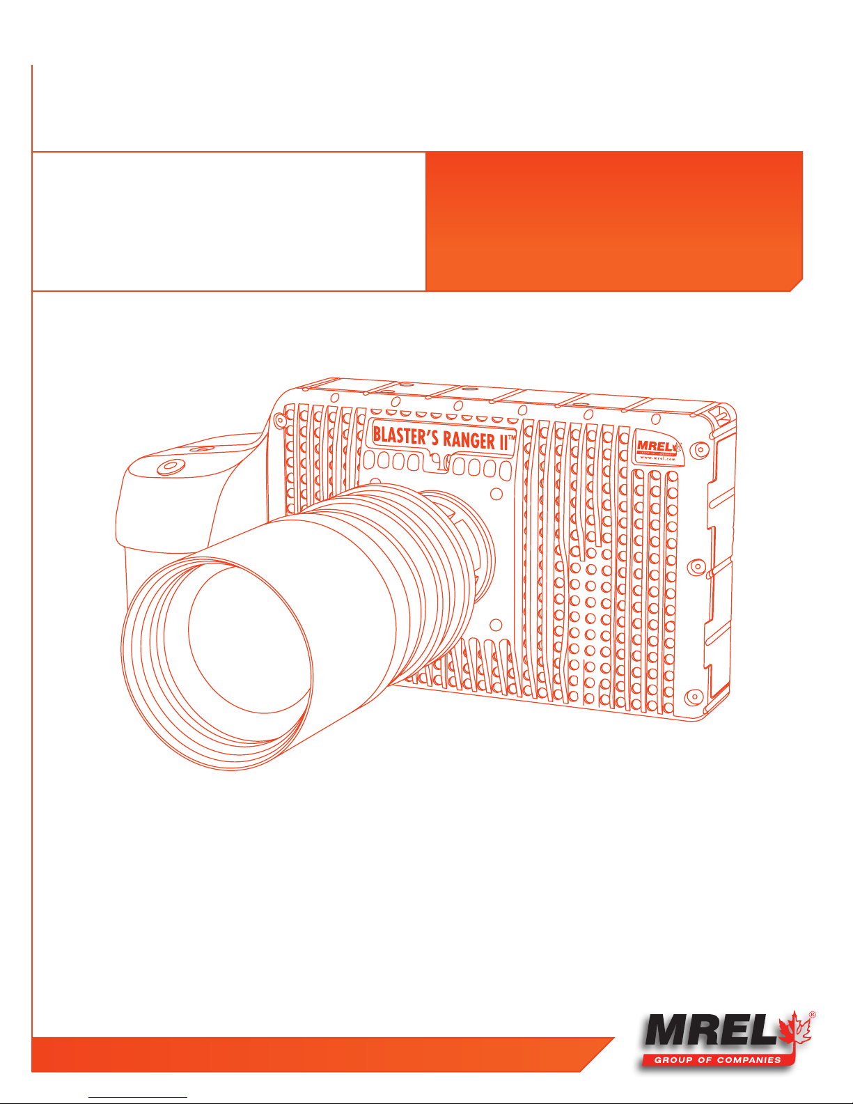
2.1 Blaster’s Ranger II™ High Speed Digital Video Camera
The Blaster’s Ranger II™ High Speed Digital Video Camera is encased in a rigid steel housing. The housing is sealed to resist dirt and
moisture and is equipped with many connection ports: the Ethernet Communication port and the Blaster’s Ranger II™ I/O Cable port. The
Blaster’s Ranger II™ I/O Cable is comprised of a total of three connectors: Sync In, Sync Out and Trigger In.
Photographs of the Blaster’s Ranger II™ are shown below. The Mounting Adapter is attached to the bottom of the Blaster’s Ranger II™
to allow the Blaster’s Ranger II™ to be quickly mounted onto the Tripod’s Grip Action Ball Head (shown in Section 2.2.3). The Mounting
Adapter and the Tripod’s Grip Action Ball Head are part of the Blaster’s Ranger II™ Accessories Package. The Blaster’s Ranger II™ is
equipped to accept any standard C-Mount Lens.
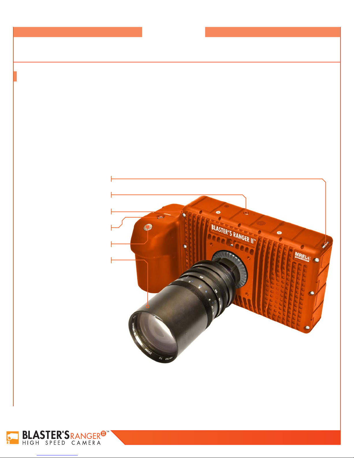
2.1.1 Camera Front
Camera Strap Attachment
Top Mount 1/4 - 20
USB port
Power Button
Trigger Button
Camera Lens
Blaster’s Ranger II Operations Manual - Edition 2.0
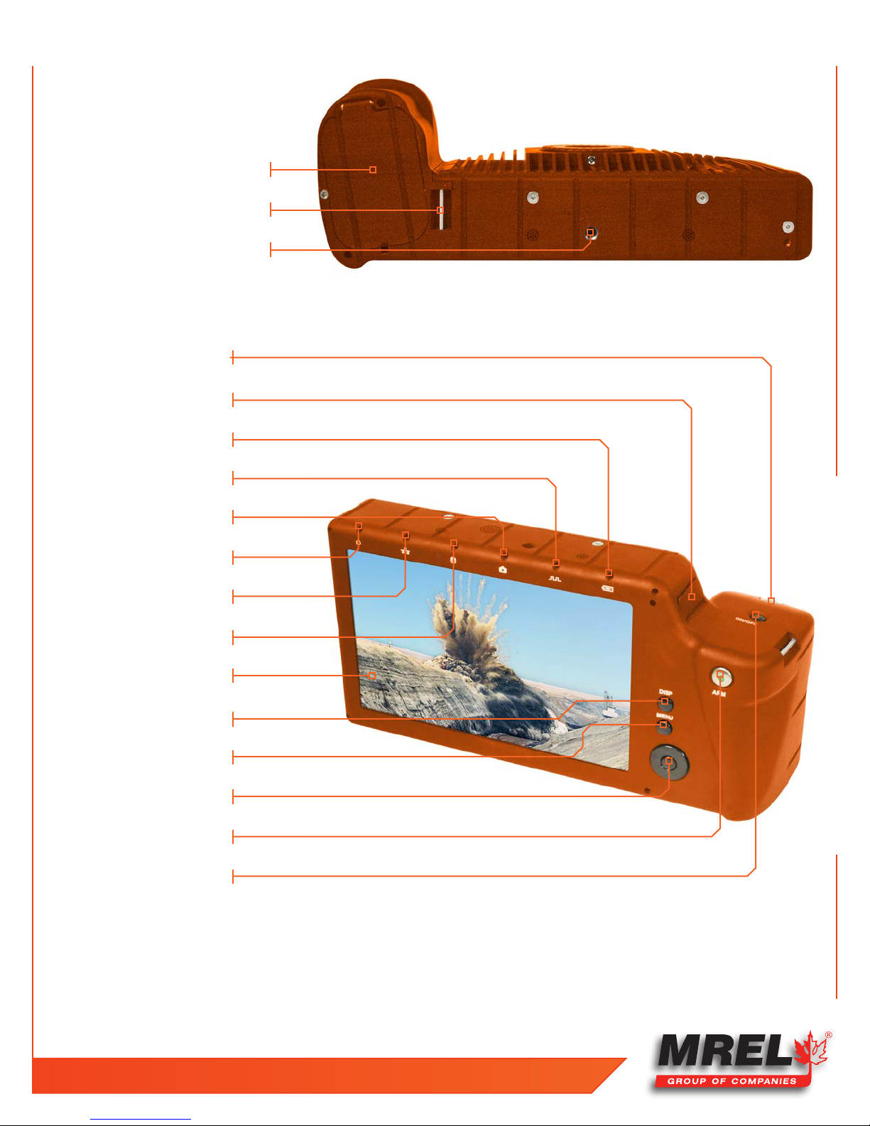
2.1.2 Camera Bottom
Battery Door
Hand Strap Attachment Point
1/4 - 20 Tripod Mount
2.1.3 Camera Back
Trigger Button
USB port
Battery Status LED
7
Sync Activity LED
Camera Status LED
Power LED
Network Activity LED
Storage Activity LED
Touch-Screen Display
Display Button
Menu Button
D-Pad
Arm Button
Power ON/OFF Button
T: +1-613-545-0466 F: +1-613-542-8029 www.mrel.com
8
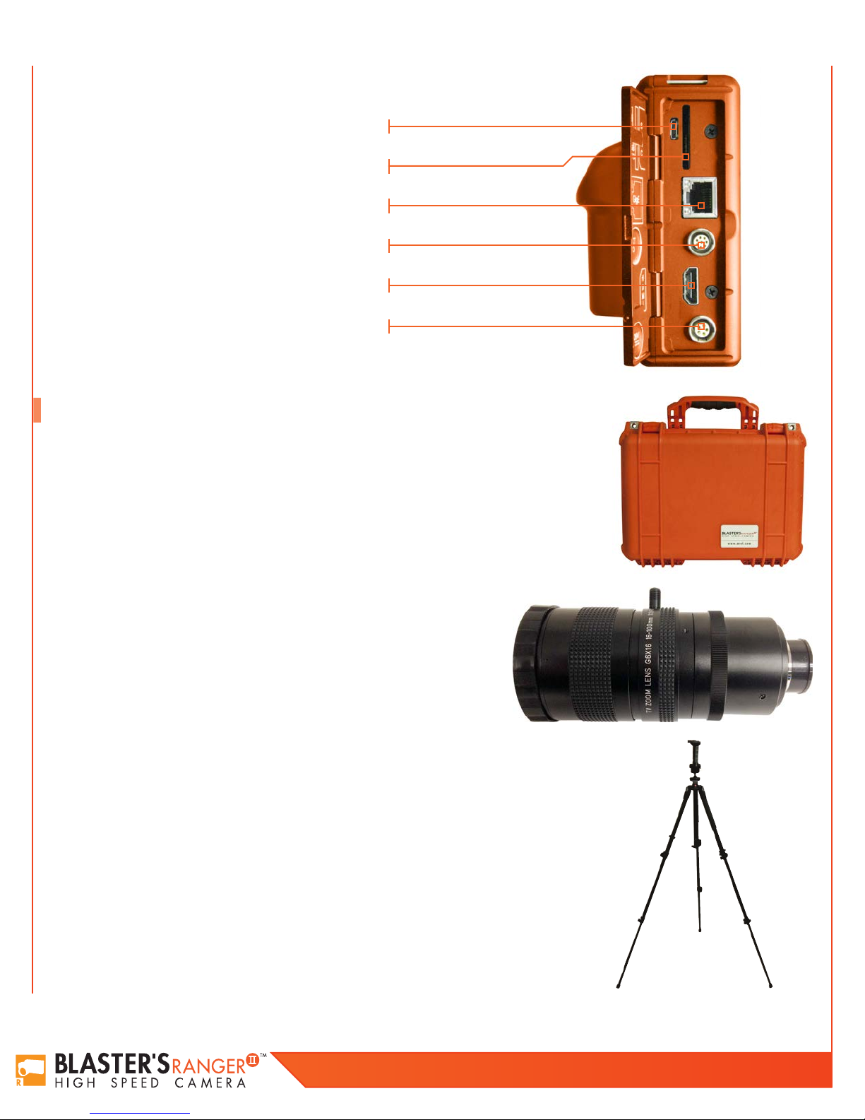
2.1.4 Camera Input Output Panel
USB OTG (Micro A/B connector)
SDHC Port
GigE Port (RJ45 connector)
Sync I/O, Trigger (Lemo connector)
HDMI Port (Type A connector)
DC Power In (Lemo connector)
2.2 BLASTER’S RANGER II™ ACCESSORIES
2.2.1 Protective Carry Case
The Carry Case is designed to contain, for transportation and storage all the components required for setup
and use of the Blaster’s Ranger II™ in the field. The Carry Case is a pelican case which has water resistance
capabilities.
2.2.2 Zoom Lens
The Blaster’s Ranger II™ is supplied with a Zoom Lens appropriate for imaging of blasts.
The Zoom Lens (16-100 mm) is for the model of resolution of 1280X1024, and shown to
the right. Zoom lens (12.5 – 75 mm) is for the model of resolution of 800X600.
2.2.3 Tripod and Grip ball Head
This is an all aluminum Tripod with a 3/8” mounting screw. This Tripod is designed to support the
Grip Action Ball Head with the
fit inside the Protective Carry Case.
Blaster’s Ranger II™
attached. This is the only item that does not
Blaster’s Ranger II Operations Manual - Edition 2.0
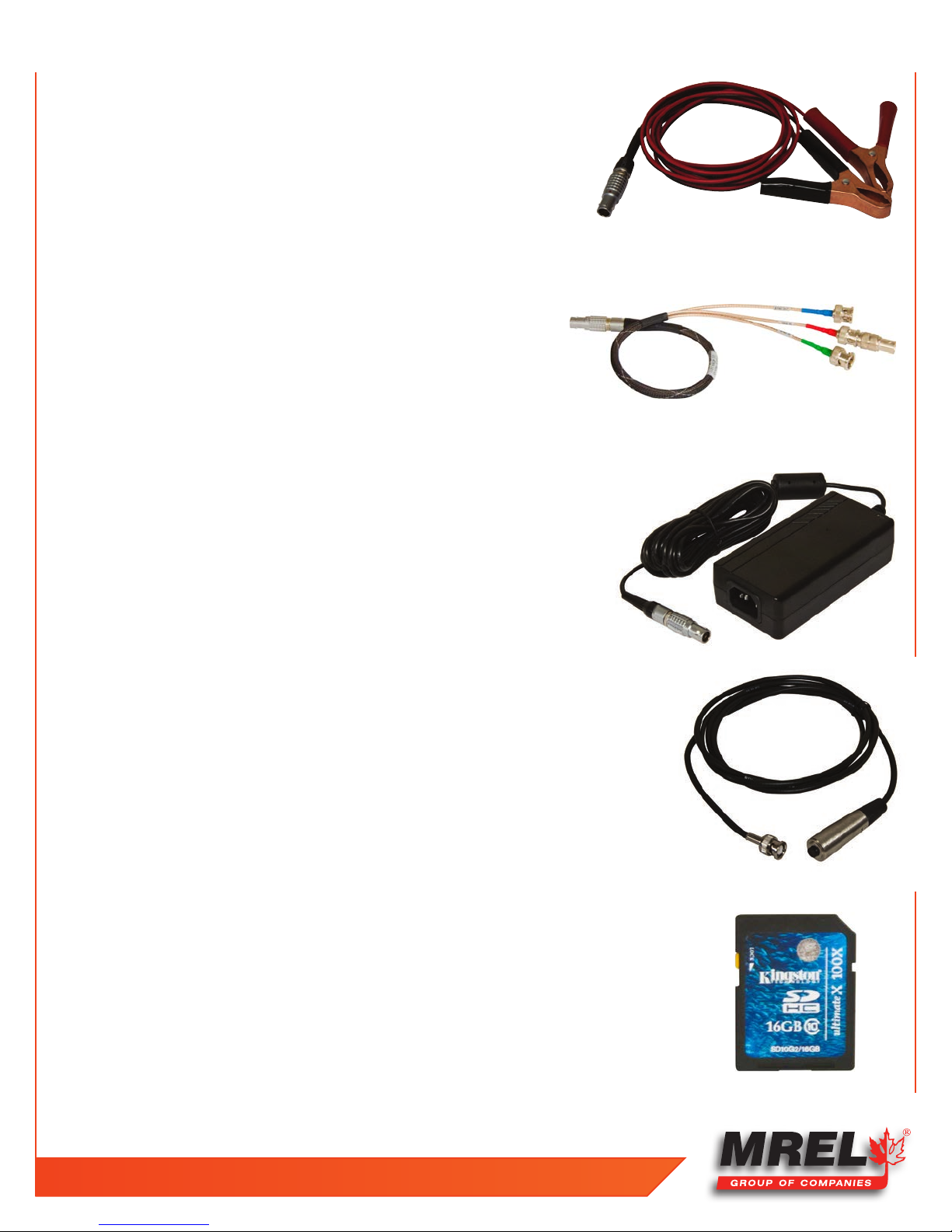
2.2.4 Blaster’s Ranger II™ DC Power Cable
The
Blaster’s Ranger II™
internal battery within the
of continuous
Blaster’s Ranger II™
Controller Power Cable Adaptor is used to recharge the
Blaster’s Ranger II™
operation before recharging.
. The internal battery is rated for 5 hours
2.2.5 Blaster’s Ranger II™ I/O Cable
The Blaster’s Ranger II™ I/O Cable is comprised of a total of three connectors: Sync
In(blue), Sync Out (green) and Trigger In (red).
2.2.6 Blaster’s Ranger II™ AC Adapter
9
The
Blaster’s Ranger II™
with a range of 12-26 VD C. The most readily available source of power in the field is
usually an automotive 12 Volt DC battery, so the
is equipped with automotive battery terminal clamps.
DC Power Cable will connect to an external DC power supply
Blaster’s Ranger II™
DC Power Cable
2.2.7 Trigger Switch Cable With Button
The trigger cable with switch allows the user to trigger the camera at a distance. The user can extend
this cable with the appropriate BNC connectors and a reel of RG-58 coaxial cable.
2.2.8 SD Card
The Blaster’s Ranger II™ is shipped with a 16GB high performance SD-Card.
T: +1-613-545-0466 F: +1-613-542-8029 www.mrel.com

10
2.2.9 USB Communication Cable
It is a USB-A to USB-Micro-B cable. Once connected via the Blaster’s Ranger II™ OTG
port to a PC, any mass storage device on the camera can be accessed by the PC. This
includes an SD-Card, Solid State Drive, or thumb drive in the USB port.
2.2.10 ProAnalyst® TrackOne Edition Software
ProAnalyst® TrackOne Edition allows auto-tracking of one feature, and manual tracking of up to
32 features. ProAnalyst® allows the user to export data to Excel or Matlab with ease for further
analysis or graphing. This software is provided under licence from Xcitex, and as such requires
the use of the included software key for installation. Instructions on using ProAnalyst® TrackOne
Edition are included in Chapter 7.
Blaster’s Ranger II Operations Manual - Edition 2.0
Chapter 3
Getting Started
11
T: +1-613-545-0466 F: +1-613-542-8029 www.mrel.com
12
Overview
This chapter provides an outline of how to setup the Blaster’s Ranger II™. This chapter assumes
that the User will first want to unpack the
Blaster’s Ranger II™ and set it up in an office
environment in order to learn the camera controls.
3.1 Introduction
This chapter provides a detailed description of the setup procedure for the Blaster’s Ranger II™. The Quick Setup Guide is also included in
Chapter 3.5. For instruction on using the Blaster’s Ranger II™, please refer to Chapter 4. For Instruction on using the Blaster’s Ranger II™
in the field, please refer to Chapter 5.
3.2 Powering Up
The Blaster’s Ranger II™ can be powered by its rechargeable 3.7V Li-Ion battery or the external 12V power supply cable. Both are
included with the camera. The battery is fully charged at the factory. The battery door is located on the underside of the camera.
The Li-Ion battery will power the Blaster’s Ranger II™ for up to several hours depending on configuration and mode of operation.
When a new battery is installed, it must go through one complete discharge/recharge cycle to calibrate its internal “gas gauge.”
NOTE:
Until that time you will find that the % of charge shown on the lower right of the camera display as well as on any camera
control software will not be correct.
3.2.1 Removing the Battery
1. Turn the Blaster’s Ranger II™ upside down to access the battery compartment.
2. Slide the battery door latch to the open position. The spring loaded door will open.
3. Move the battery clasp away from the edge of the battery.
4. The battery may slide out easily, or you may need to hold the camera upright and shake it gently to get the internal battery
connector to release.
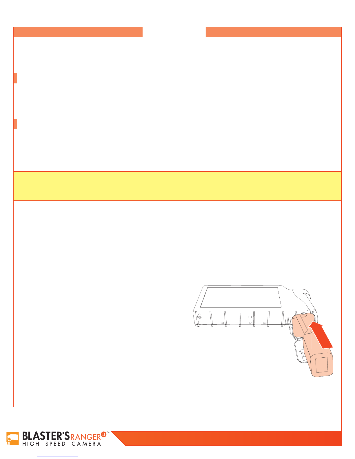
3.2.2 Installing the Battery
1. Open the battery door (follow steps 1-2, above).
2. Look into the battery compartment and notice the connector at the
bottom.
3. Look at the battery and notice the corresponding mating connector.
4. Orient the battery appropriately and slide it into the compartment.
5. With the battery seated properly in the compartment, the battery
clasp will close, securing it in place.
6. Close the battery access door.
7. Slide the battery door latch closed.
8. The Blaster’s Ranger II™ should now power up. If it does not, please
follow the instructions below for connecting the DC power supply and
charging the battery.
9. With the Blaster’s Ranger II™ powered up, press the Menu button once to get the menus and status bar to appear on the LCD
display.
Figure 1: Inserting the Battery
Blaster’s Ranger II Operations Manual - Edition 2.0
13
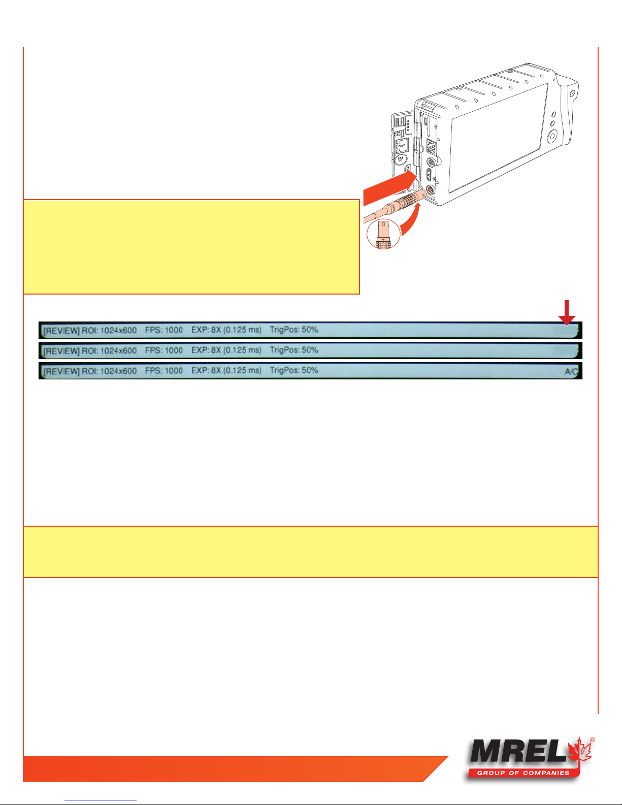
3.2.3 Attaching the External DC Power Supply
The 12V DC Power Supply operates on 100-240VAC, 50-60Hz. The socket is a
standard IEC 13, used worldwide for all types of electronic equipment.
1. Attach a power cord to the power supply and connect it to an AC power
outlet.
2. Attach the power supply output cord to the camera via LEMO connectors.
The LEMO connector is keyed: the red dot on the connector will face the
LCD side (back) of the camera.
NOTE: If the camera was powered down before connecting the power supply,
it will now power up. While operating on battery power the Battery
Status on the Status bar will show a negative number -88%. (See
Figure 3: Battery Charge Indicator on Status Bar.) When connected to a
power supply (with the battery installed) the number becomes positive.
If no battery is present it changes to A/C.
Figure 2: Attaching the DC Power Supply
Figure 3: Battery Charge Indicator on Status Bar
-88%
88%
3.2.4 Charging the Battery
The Blaster’s Ranger II™ battery does not charge automatically when the camera is attached to an external power supply while
operating. Charging mode is initiated by pressing the ON/OFF button. When the battery is present while the camera is attached to an
external power supply, the ON/OFF button will toggle the camera through three states:
1. Normal operation;
2. Charging (non operational);
3. Off.
NOTE: Pressing the ON/OFF button toggles the camera between three Modes if both the battery and external power supply are
present. It toggles the camera between two Modes: ON/OFF if either the battery or the external supply is not present. (See
Table 1: ON/OFF Button on page 9
T: +1-613-545-0466 F: +1-613-542-8029 www.mrel.com

14
Table 1: ON/OFF Button
Battery
Present
• • 1. Operating Power / Camera / Battery (Green, Amber, or Red) Batt: xx%
• • 2. Charging Power / Battery (Green, Amber, or Red) (LCD off)
• • 3. Off None (LCD off)
• 1. Operating Power / Camera / Battery (Green, Amber, or Red) Batt:-xx%
• 2. Off (LCD off)
External
Supply
• 1. Operating Power / Camera / Battery (Blue) A/C
• 2. Off None (LCD off)
Mode LEDs
Battery Charge %
Table 2: Battery LED States
Operating / Charging Charge Status LED Behavior
Operating >15% Green
Charging > 15% Blinking Green
Operating < 15% > 5% Amber
Charging <15% >5% Blinking Amber
Operating <5% Blinking Red
Charging <5% Blinking Red
Indicator
Operating Not Installed Blue
3.3 Mass Storage
The Blaster’s Ranger II™ camera is equipped with from 2GB to 8GB of internal high-speed internal memory. Images stored in this memory
may be reviewed on the camera, external monitor via HDMI, or PC, then saved to any of four types of mass storage devices:
1. Solid State Hard drive installed in the Blaster’s Ranger II™ at the factory (it is optional).
2. SD-Cards (SDHC) inserted by the operator into the SDHC slot on the side of the Blaster’s Ranger II™.
3. USB devices such as thumb drives or USB external hard drives (not included) connected via the USB port.
4. Memory devices on a networked PC using Custom Software .
3.3.1 Blaster’s Ranger II™ Solid State Hard Drives (Internal SSD)
Solid state hard drives (SSDs) are optional on the Blaster’s Ranger II™. These drives serve as mass storage devices for the camera and
are installed in the camera at the factory. Image data from the Blaster’s Ranger II™ high-speed internal memory may be downloaded to
the SSD, thus making room for the next high-speed image capture. While the SSD does not add to the recording time of the camera (the
number of images it can record in one session), it does allow the user to download large quantities of image data without ever connecting
the Blaster’s Ranger II™ to a PC or other external device.
Blaster’s Ranger II Operations Manual - Edition 2.0
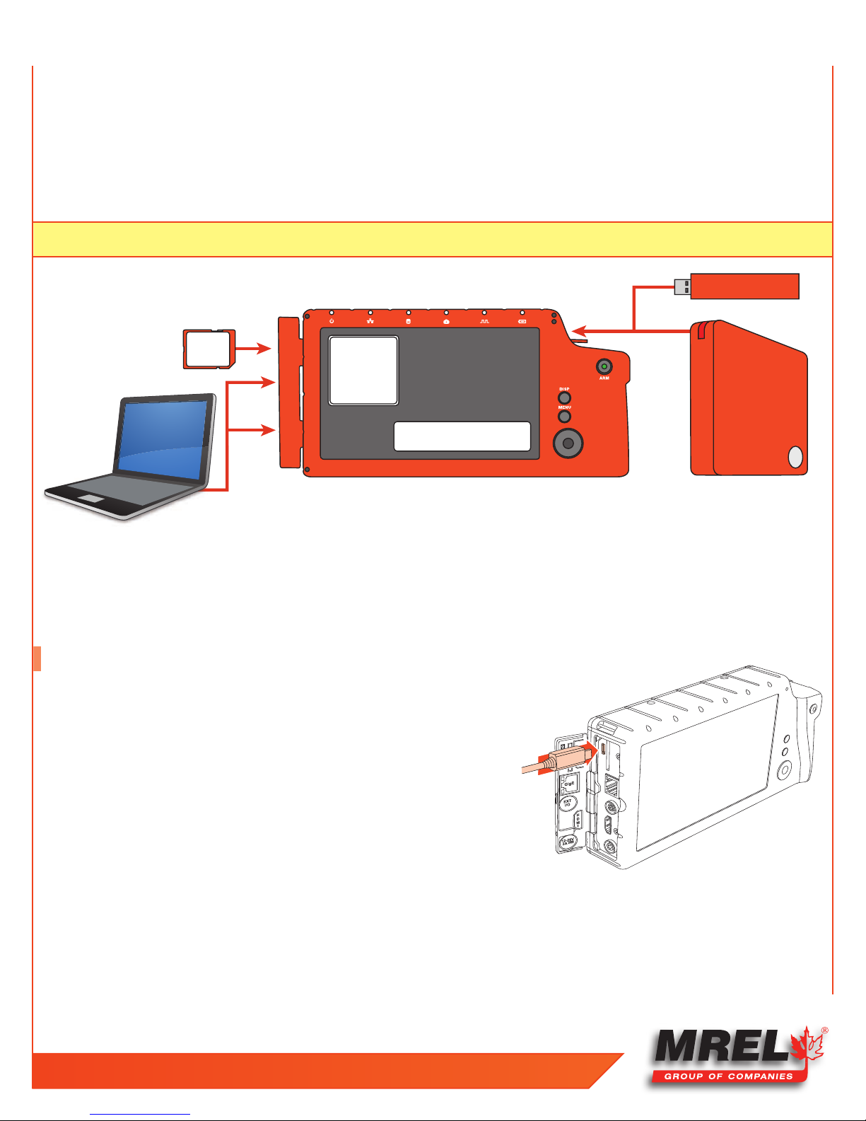
INTERNAL SDD
64/128/256GB
INTERNAL HIGH-SPEED MEMORY
2/4/8GB
USB
HARD DRIVE
USB THUMB DRIVE
USB PORT
GIG-E
USB
OTG
SD
CARD
G
3.3.2 SD-Card
The Blaster’s Ranger II™ is shipped with a 16GB high performance SD-Card. This card has two functions:
1. It can be used as a mass storage device for downloading and distributing images. SD-Cards and card readers are very commonly
used storage devices among PC users and photographers.
2. Any field software updates for the Blaster’s Ranger II™ will be installed via the SD-Card.
NOTE:
An SD-Card when used for a software update must be reformatted before it can be reused as a mass storage device.
Figure 4: Mass Storage
15
3.3.3 USB Port
The Blaster’s Ranger II™ will act as a Host to any USB mass storage device connected at the USB port. Image data may be saved to
these devices.
3.4 USB-On The Go!
The USB-OTG port allows the camera to be connected as a slave to any PC using
a USB-A to USB-Micro-B cable. Once connected via the Blaster’s Ranger II™ OTG
port, any mass storage device on the camera can be accessed by the PC. This
includes an SD-Card, Solid State Drive, or thumb drive in the USB port.
To use this option:
1. Power up the Blaster’s Ranger II™.
2. Install thumb drive and/or SD-Card in the camera.
3. Attach the camera to the PC via the camera’s USB-OTG port, which is next to
the SD-Card slot on the side of the camera. As each device is located by the
PC an Autoplay window on the PC will open. This is a very simple way to transfer image data to a PC. This is for file access only-there is no way to control the camera via USB-OTG.
4. When you are finished, you need to eject the media from the PC. Click on the “Safely Remove Hardware and Eject Media” icon on
your computer’s task bar and select “Eject Camera.”
Figure 5: Attaching the USB Cable
T: +1-613-545-0466 F: +1-613-542-8029 www.mrel.com
16
NOTE: Any device that is connected to the camera after the camera and PC are connected will not be seen by the PC.
Table 3: Blaster’s Ranger II™ Mass Storage Functionality
Blaster’s Ranger II™ Utilities: Target Drive(s) Functions
System/Storage/Explore SSD/USB/SDHC Move, Copy, and Delete Image files
System/Storage/Format SSD/USB/SDHC Format drive
System/Storage/Eject USB/SDHC Safely Eject Media
Review/Save SSD/USB/SDHC Save image Data from Internal High-Speed Memory
Record Still SSD/USB/SDHC Save a single still Image
Autosave SSD/USB/SDHC Autoave image Data from Internal High-Speed Memory
PC via Gig-E Connection: Target Drive(s) Functions
Explore SSD/USB/SDHC
Web Application SSD/USB/SDHC
Custom Software App PC Drives+SSD/USB/SDHC All Blaster’s Ranger II™ Utilities
PC via USB-OTG SSD/USB/SDHC
Open, Copy files, multiple files, directories From
Blaster’s Ranger II™ to PC only
Open, Copy files (one at a time) from
Blaster’s Ranger II™ to PC only
Move, Copy and Delete all files and directories to
and from Blaster’s Ranger II™
3.5 Camera setup
There are several precautions that must be remembered prior to using the Blaster’s Ranger II™. The suggested procedure for assembly of
the system is detailed in the following sections.
3.5.1 Blaster’s Ranger II™ Setup
Open and extend the Tripod legs. Attach the Grip Action Ball Head to
the top of the Tripod using the 3/8”screw mount. Remove the Mounting
Adapter from the top of the Grip Action Ball Head and connect the
threaded screw of the Mounting Adapter to the bottom of the camera.
Be sure that the Lens arrow is pointing towards the front of the Lens.
Attach the Mounting Adapter to the Grip Action Ball Head. Secure the
camera using the locking lever located on the Grip Action Ball Head. It
is also good practice to utilize the locking lever pin ensure the locking
lever does not come free during operation.
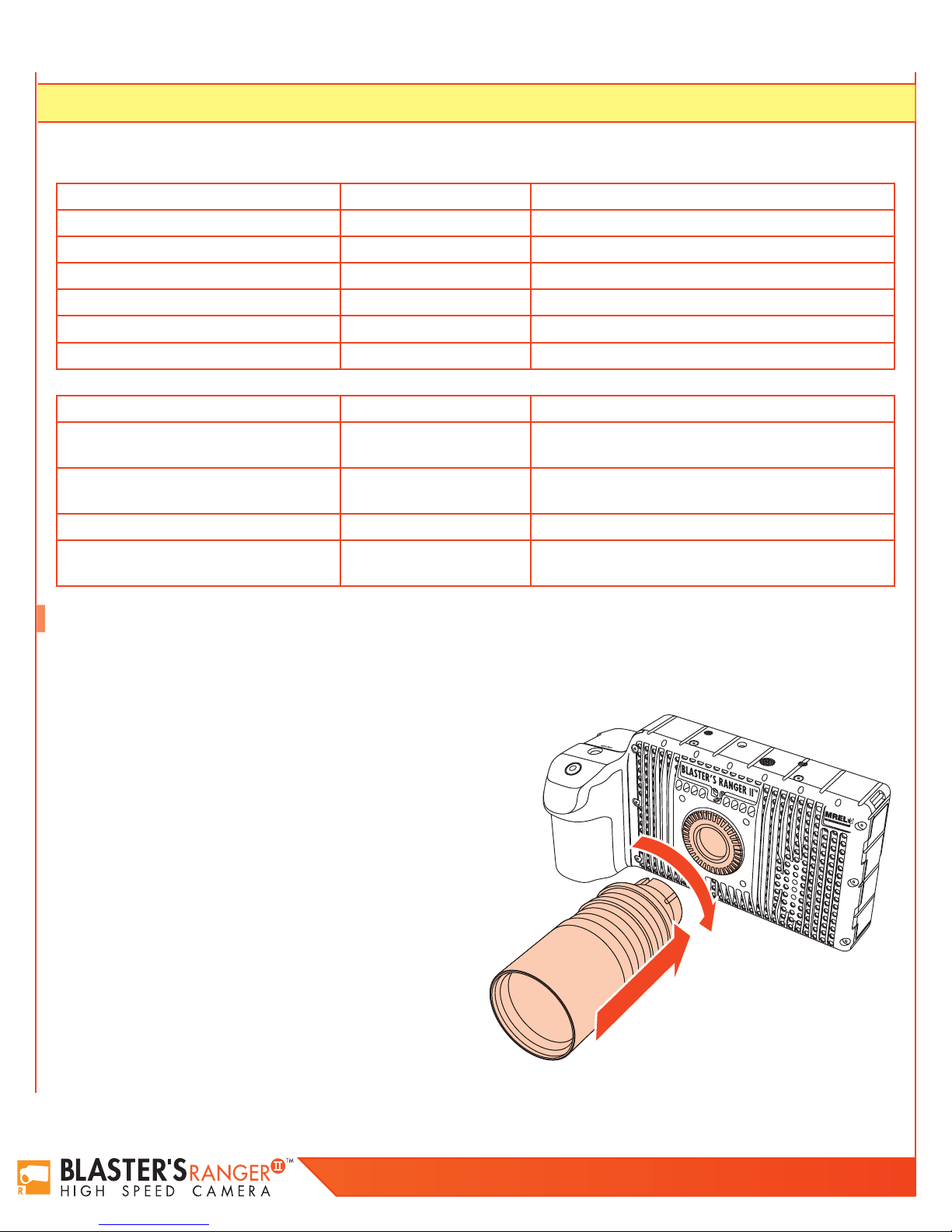
3.5.2 Mount the C-Mount Zoom Lens to the
camera
Remove the lens receptacle cover from the camera’s C-mount. This is a
cover that is installed at the factory to protect the camera optics and sensor from dust contamination.
Figure 6: Mounting the lens
Blaster’s Ranger II Operations Manual - Edition 2.0
NOTE: Whenever threading lenses on or off the camera, face the camera lens down so that any contamination on the threads will tend
to fall away from the camera rather than into it.
17
Thread the C-mount lens into the lens mount located in the front of the camera.
DO NOT over tighten the lens! The lens should be “finger tight” only--just tight
enough that you can adjust focus and aperture without unscrewing the lens.
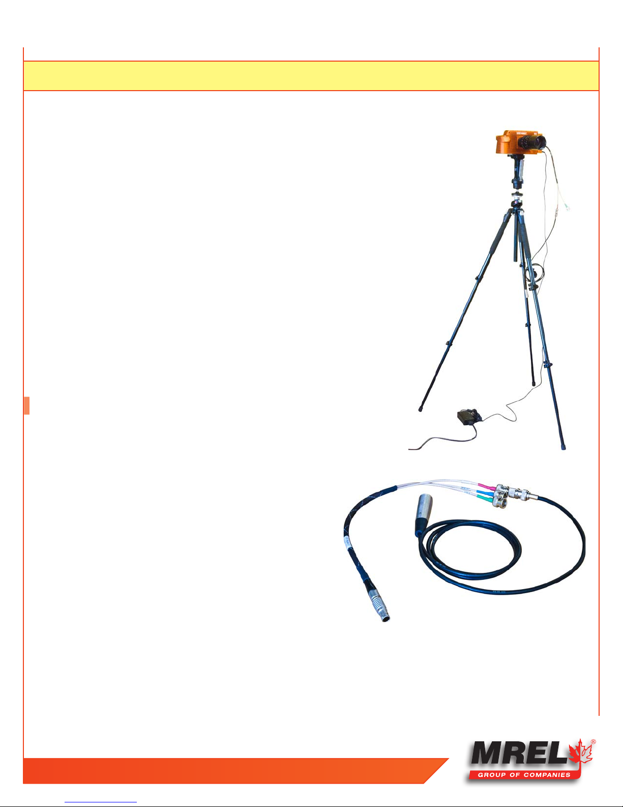
3.5.3 Blaster’s Ranger II™ I/O Cable and Trigger Switch
Cable
The I/O Cable has 8-pin LEMO camera connector and BNC connectors for SyncIn, Sync-Out, and Trigger-In. The Trigger switch cable is attached to the Trigger-In
connector.
3.5.4 DC Power Connection
The camera can be powered by its rechargeable 3.7V Li-Ion battery ,12 V AC/
DC adapter or the external 12V DC battery. See Figure 2: Attaching the DC
Power Supply.
Refer Quick Start Guide to power on the camera and get familiar with the
camera.
Figure 7: Blaster’s Ranger II™ Complete
3.6 Camera Display and Menu
Navigation Buttons
The Display Button, Menu Button, and Directional Pad (D-Pad) are found on
the back of the camera to the right of the LCD.
When the camera powers on for the first time, the default display is a live
image with no menu displayed.
Pressing the Display (DISP) Button while toggles the LCD between three
modes:
1. Display off;
2. Display on;
3. Display on with Histogram.
When there is captured video to review, a mode with playback controls is added.
The Menu Button toggles the on screen menus on and off. While navigating menus, the Menu button is used to go backward through
levels of the menu. For example, if you are navigating a Menu pressing the Menu button will return you to the Menu Bar. (See Menu
Terminology, below.)
Figure 8: I/O Cable and Trigger connected
T: +1-613-545-0466 F: +1-613-542-8029 www.mrel.com
18
The D-Pad is used to move within menus and dialogs. It has an “OK” button in its center for selecting menu items and options.
While navigating through menus, the current location is indicated by a change of color from white or green to gray. When navigating a
Menu, the drop down selections will always appear in the left most column. The selected menu will appear in white letters in the Menu
Bar. Selected or Enabled items turn green once the cursor is moved away from them.
Table 4: Menu Terminology
Menu Bar Across the top of the display: System, Record, Control, Display, Review
Menu
Element The menu options i.e. Name, Network, etc. are called Menu Elements
Dialog Box
Status Bar
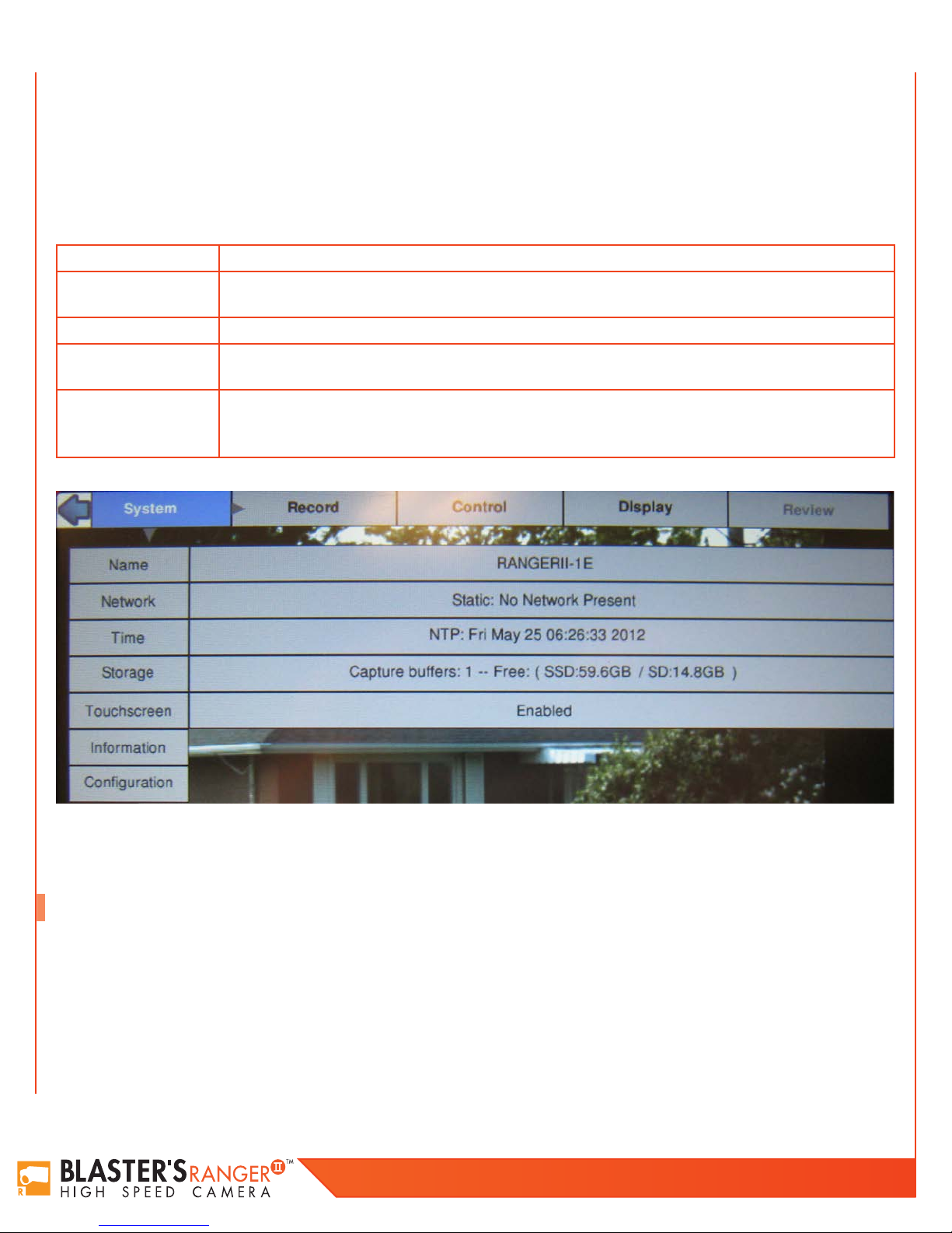
Figure 9: System Menu
Having Made a selection from the Menu Bar, a drop down Menu Appears, such as the System Menu shown
below. Present status for items in the selected menu are listed.
Having chosen an item from a menu, a dialog box may open such as the Frame Rate and Resolution.
This is often a place where the user may make choices and/or input data.
The Status Bar is located at the bottom of the display. Information includes (from left to right): Operating
Mode (Live= live view, CAP= recording, REVIEW= playback); ROI= Resolution; FPS= Frame rate;
EXP= Exposure; Trigger Position; and Power /Batter Status (A/C= no battery, xx% = battery charge)
3.7 Using the Touchscreen
The Blaster’s Ranger II™ 7” display uses touchscreen technology that allows the user to enter certain data directly with the touch of a
finger rather than via the D-Pad. While most of the menu system is not accessible through the touchscreen at the time of this writing, you
will find that it has been implemented in some of the most entry-intensive portions of the user interface.
The touchscreen is implemented for:
• The alphanumeric keyboard.
• The playback controls.
Blaster’s Ranger II Operations Manual - Edition 2.0
 Loading...