

Page 1

The Signature Series is NOT designed for amateur installation. Installation SHOULD be performed by an authorized technician.
Please read this manual carefully before installation and keep it for future reference.
Owner & Installation
Manual
Signature Series
MAHM*ETA AIR Handler
The Signature Series is NOT designed for amateur installation. Installation SHOULD be performed by an authorized technician.
Please read this manual carefully before installation and keep it for future reference.
Page 2
INSTALLATION INSTRUCTIONS
MAHM*ETA Series Air Handler
This manual must be left with the homeowner for future reference.
This is a safety alert symbol and should never be ignored. When you see this symbol on labels or in
manuals, be alert to the potential for personal injury or death.
Table of Contents
Shipping and Packing List ...........................................3
General........................................................................3
Requirements ..............................................................3
Installation Clearances ................................................4
Installation ...................................................................4
Condensate Drain........................................................6
Duct System and Filters .............................................8
Brazing Refrigerant Lines............................................9
Sealing the Unit .........................................................11
Electrical Connections............................................... 11
.........................................15
...............................16
Operation Inspection .................................................16
Operation...................................................................17
Maintenance..............................................................17
Professional Maintenance .........................................17
Cabinet Insulation......................................................18
Use of Air Handler During Construction.....................18
.......2
WARNING
Improper installation, adjustment, alteration, service
or maintenance can cause property damage, personal
injury or loss of life. Installation and service must be
performed by a licensed professional HVAC installer or
equivalent, service agency, or the gas supplier.
sheet metal edges can result in personal injury. Take
and protective clothing.
CAUTION
Manufactured By
MRCOOL LLC
Hickory, KY 42051
IMPORTANT
The Clean Air Act of 1990 bans the intentional venting
of refrigerant (CFCs, HCFCs and HFCs) as of July
1, 1992. Approved methods of recovery, recycling or
may be levied for noncompliance.
Save these instructions for future reference
507788-01C mrcool.com Page 1 of 20
*P507788-01C*
(P) 507788-01C
Page 3
MAHM*ETA
1 (25)
LINE VOLTAGE
INLETS
(Top and Left Side)
3/4
(19)
1 (25)
14-1/2
(368)
TOP VIEW
CIRCUIT
BREAKER
COVER
SUPPLY AIR
OPENING
C
B
1 (25)
LOW VOLTAGE
INLETS
(Top and Right Side)
2-3/8
(60)
4-3/8
(111)
LINE VOLTAGE
INLETS
(Top and Right Side)
LOW VOLTAGE
INLETS
(Either Side)
DETAIL OF PIPING PLATE
3/4 (19)
SUCTION
LINE
LIQUID
LINE
2-3/4
(70)
1-3/4
(44)
4-3/4
(121)
CONDENSATE
CONDENSATE
3-1/2
(89)
22
(559)
DRAINS (2)
(Horizontal)
DRAINS (2)
(Upflow and
Downflow)
NOTE:
Dimensions
A
B
C
D
A
1-1/8
(29)
AIR FLOW
PIPING
PLATE
D
OPENING
CONDENSATE DRAIN
PIPING PLATE (3)
(2-1/4 x 3-3/4)
FILTER
ACCESS
1-1/8
(29)
SUCTION
LINE
LIQUID
LINE
1/2
(13)
20-3/8
(518)
OPENING
1-1/8
(29)
FRONT VIEW SIDE VIEW
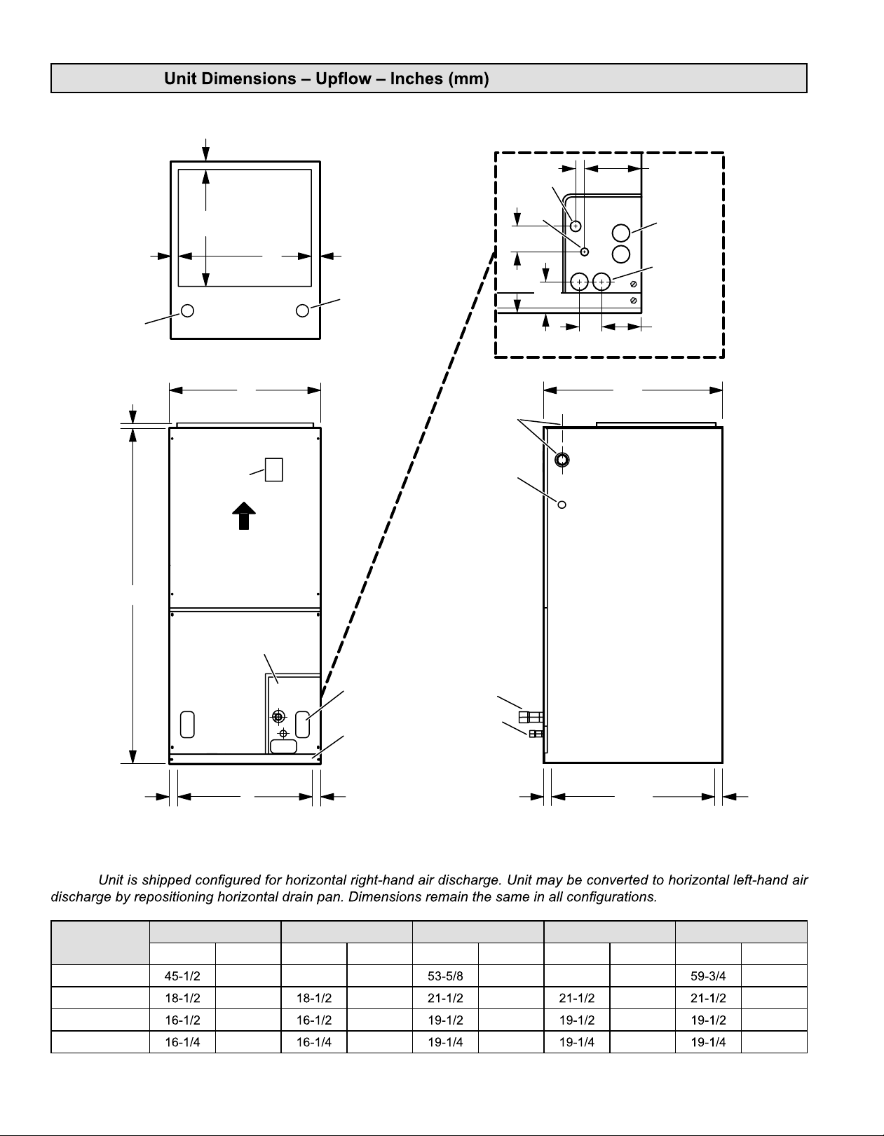
024 030 036 / 042 048 060
in. mm in. mm in. mm in. mm in. mm
1156 47 1194 1362 55 1397 1518
470 470 546 546 546
419 419 495 495 495
413 413 489 489 489
507788-01Cmrcool.comPage 2 of 20
Page 4
Shipping and Packing List
pertaining to this type of equipment should be determined
Package 1 of 1 contains:
Check the air handler for shipping damage; if found,
immediately contact the last carrier. Check the unit rating
General
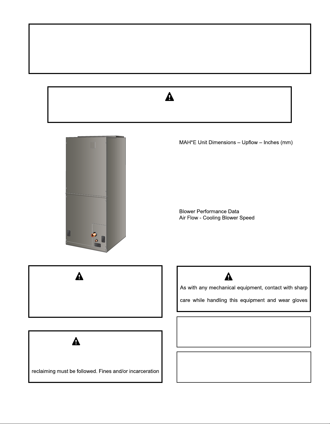
The MAHM*ETA
is designed for indoor installation only. As shipped, the
right-hand air discharge applications. Horizontal drain
in the horizontal left-hand air discharge position. Various
accessories are available and listed in the MAHM*ETA Product
This instruction is intended as a general guide and does
authorities having jurisdiction before installation.
as the instructions supplied in separate equipment, before
starting the installation.
In addition to conforming to manufacturer’s installation
instructions and local municipal building codes, installation
(NFPA) standards: “Standard for Installation of Air
Conditioning and Ventilation Systems” (NFPA No. 90A)
and “Standard for Installation of Residence Type Warm Air
Heating and Air Conditioning Systems” (NFPA No. 90B).
All models are designed for indoor installation only. The
must conform to the requirements of the National Electrical
Local authorities having jurisdiction should be consulted
before installation is made. Such applicable regulations
or requirements take precedence over the general
instructions in this manual.
NOTE:
Requirements
WARNING
can result in back or other type of injury.
IMPORTANT
MAHM*ETA
varying capacities. These units must be installed as
a part of a matched system as outlined in the MAHM*ETA
These instructions are intended as a general guide and do
the Installation of Warm Air Heating and Air-Conditioning
Systems (latest edition).
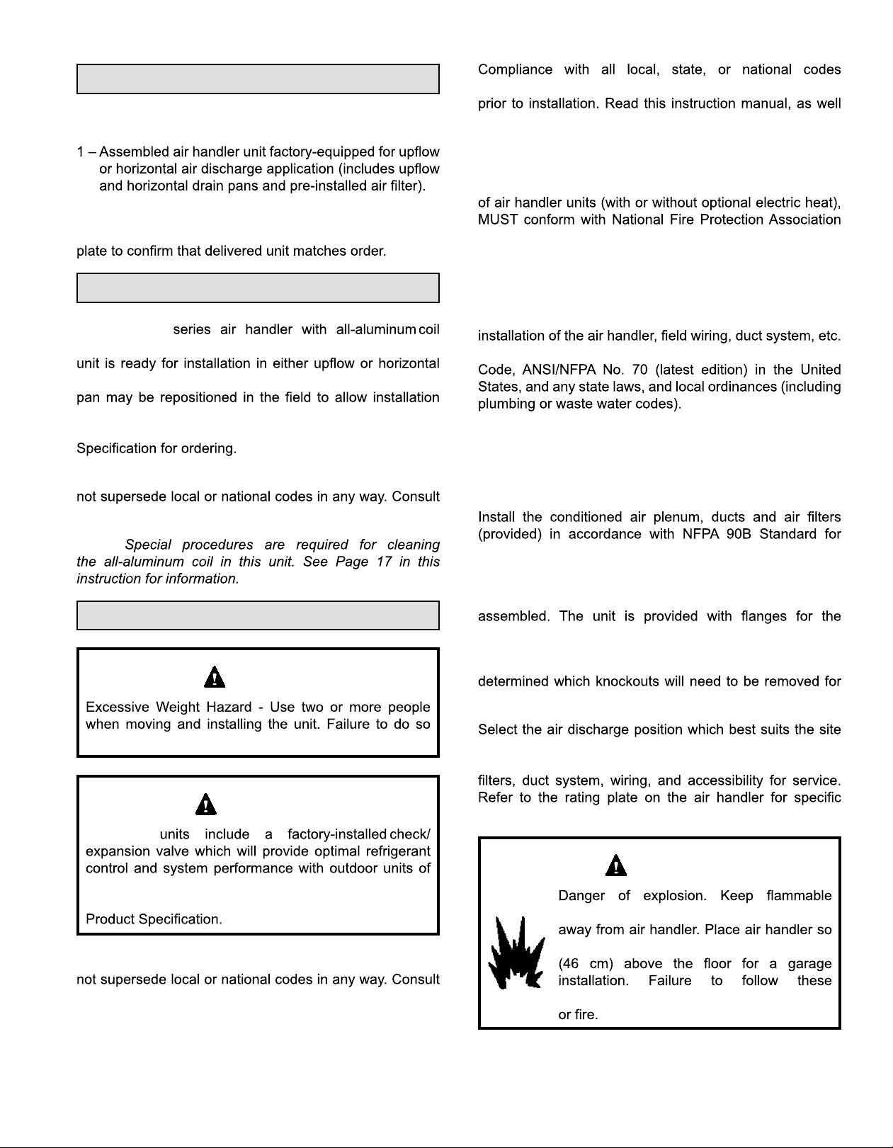
The air handler is shipped from the factory completely
connection of the duct system.
Do not remove the cabinet knockouts until it has been
the installation.
conditions. Consider required clearances, space, routing
requirements for refrigerant line, condensate disposal,
information.
WARNING
materials and vapors, such as gasoline,
that heating elements are at least 18 inches
authorities having jurisdiction before installation.
507788-01C mrcool.com Page 3 of 20
instructions can result in death, explosion,
Page 5
IMPORTANT
Excessive condensation may occur if the unit is installed
unconditioned space, apply sealant around electrical
Apply sealant on the inside of the cabinet at the
electrical controls.
single-story buildings.
When a MAHM*ETA
be:
• 320 square inches for -024 models;
• 360 square inches for -030 and -036 models;
• 450 square inches for -042 thru -060 models
determine if the open area meets the minimum open area
listed above.
IMPORTANT
This unit is approved for installation clearance to
combustible material as stated on the unit rating
plate. Accessibility and service clearances must take
precedence over combustible material clearances.
The air handler must be installed so that free access is
compartment.
NOTE:
NOTE:
NOTE:
NOTE:
If a return air plenum is used, the return air grille should be
the opening, there must be adequate clearance around the
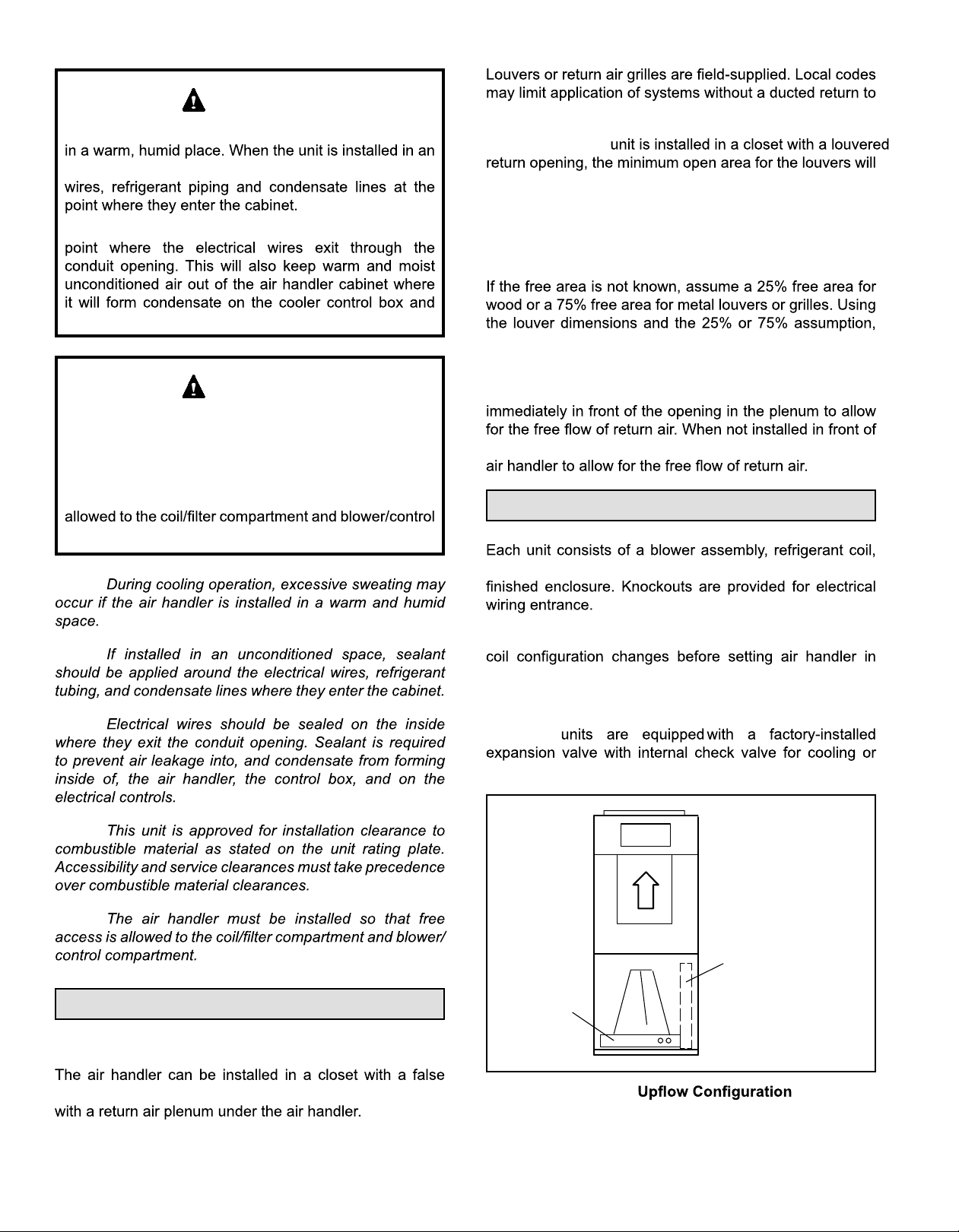
Installation
and controls in an insulated galvanized steel factory-
For ease in installation, it is best to make any necessary
place.
Refrigerant Metering Device
MAHM*ETA
heat pump application.
NOTE:
Installation Clearances
Non-Ducted Return Closet Installation
bottom to form a return air plenum. It may also be installed
HORIZONTAL DRAIN PAN
(MUST BE REMOVED)
UP-FLOW /
DOWN-FLOW
DRAIN PAN
Figure 1.
507788-01Cmrcool.comPage 4 of 20
Page 6
1. The air handler must be supported on the bottom only
frame.
2.
horizontal drain pan.
NOTE:
3.
end of the unit and level from front to back of unit (see
Figure 7).
4.
5. If the unit is suspended, the entire length of the cabinet
must be supported. If you use a chain or strap, use a
piece of angle iron or sheet metal attached to the unit
3. Place the unit in the desired location and slope unit.
Connect return and supply air plenums as required
4. Install units that have no return air plenum on a stand
air return.
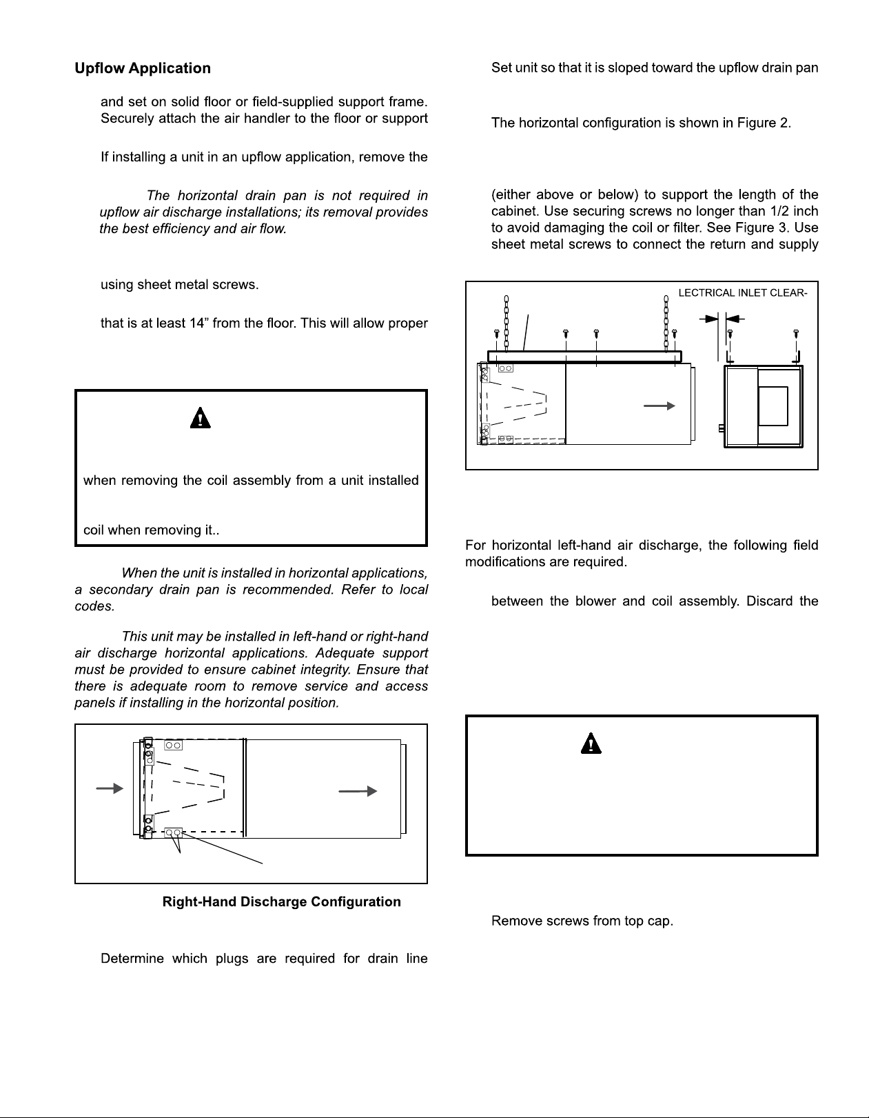
Horizontal Applications
IMPORTANT
When removing the coil, there is a possibility of danger
of equipment damage and personal injury. Be careful
in right- or left-hand applications. The coil may tip into
the drain pan once it is clear of the cabinet. Support the
NOTE:
NOTE:
air plenums as required.
ANGLE IRON OR SHEET
METAL
MAXIMUM 1/2"
LONG SCREW
AIR FLOW
FRONT WEIVDNEWEIV
E
ANCE 4 IN. (102 MM)
Figure 3. Suspending Horizontal Unit
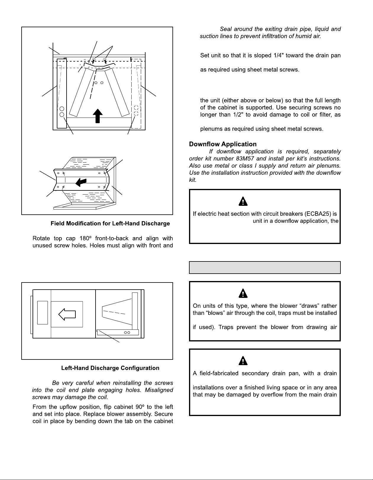
Left-Hand Air Discharge
1. Remove access panels and the corrugated padding
corrugated padding.
2. Pull the coil assembly from unit. Pull off the horizontal
drain pan.
3. Remove the drain plugs from back drain holes on
horizontal drain pan and reinstall them on front holes.
IMPORTANT
After removal of drain pan plug(s), check drain hole(s)
AIR FLOW
Drains
RIGHT‐HAND DRAINS
PLUGS
Figure 2.
Right-Hand Discharge
1.
connections.
2. With access door removed, remove drain line plugs to
install drain lines.
507788-01C mrcool.com Page 5 of 20
to verify that drain opening is fully open and free of any
debris. Also check to make sure that no debris has
fallen into the drain pan during installation that may plug
up the drain opening.
4. Rotate drain pan 180º front-to-back and install it on the
opposite side of the coil.
5.
6. Remove plastic plug from left hole on coil front end
seal and reinstall plug in back hole.
Page 7
CABINET
SUPPORT
DRAIN PAN
REINSTALLED
HERE
90º
BEND
TOP CAP ROTATED TO
CORRECT POSITION
TOP CAP SCREWS
DRAIN PAN
SHIPPING
LOCATION
NOTE:
9. Flip access door and replace it on the unit.
10.
end of the unit. Connect return and supply air plenums
11. If suspending the unit, it must be supported along the
entire length of the cabinet. If using chain or strap,
use a piece of angle iron or sheet metal attached to
illustrated in Figure 3. Connect return and supply air
REINSTALLED HERE REMOVED FROM HERE
COIL SHOWN IN UPLOAD POSITION FOR EASY CONVERSION
TOP
CAP
90º
BEND
———— DRAIN PLUGS ————
ALIGN HOLES WITH
HOLES IN COIL END
PLATE. STARTING WITH
THE ROUND HOLES ON
THIS END.
BACK COIL END SEAL
Figure 4.
7.
back coil end plates. The top cap has a 45º bend on
one side and a 90º bend on the other. The 90º bend
must be on the same side as the horizontal drain pan
as illustrated in Figure 4.
NOTE:
IMPORTANT
installed in a
circuit breakers must be rotated 180° to the UP position.
See ECBA25 installation instructions for more details.
MAHM*ETA
Condensate Drain
IMPORTANT
Figure 5.
NOTE:
8.
support rail as illustrated.
in the condensate drain lines (primary and auxiliary,
through the drain lines into the air supply.
FRONT EDGE OF HORIZONTAL
DRAIN PAN
IMPORTANT
pipe to the outside of the building, is required in all
pan. In some localities, local codes may require a
secondary drain pan for any horizontal installation.
507788-01Cmrcool.comPage 6 of 20
Page 8

ABOVE
FINISHED
SPACE?
OVERFLOW DRAIN LINE
ALWAYS RUN AN OVERFLOW DRAIN LINE. IF NOT POSSIBLE TO
ROUTE OVERFLOW DRAIN LINE, INSTALL LOW VOLTAGE
OVERFLOW SWITCH KIT. WIRE KIT TO SHUT DOWN
COMPRESSOR PER INSTRUCTIONS.
PART #
X3169
COMPACT OVERFLOW SWITCH WITH 3/4” FEMALE SLIP INLET
NO
AND MALE ADAPTER, TWO PART DESIGN FOR USE WHERE
OBSTRUCTIONS PREVENT DIRECT THREADING
CLEAN OUT
PRESS IN
(DO NOT GLUE)
VENT MUST EXTEND
ABOVE HEIGHT OF
COIL DRAIN PAN BY
TWO INCHES (51MM)
VENT
MAIN
DRAIN
MAIN
DRAIN
CUT TO
REQUIRED
LENGTH
PROVIDED
PIPE NIPPLE
SIDE VIEW
2
FOR NEGATIVE PRESSURE COILS (BLOWER
AFTER COIL) TRAPS ARE REQUIRED ON ALL
DRAIN LINES CONNECTED TO COIL.
AIR HANDLER DRAIN PAN
OVERFLOW
DRAIN
YES
NOTE — WHEN A AIR HANDLER IS LOCATED
ABOVE A FINISHED SPACE THE SECONDARY
DRAIN PAN MUST HAVE A LARGER FOOTPRINT
THAN THE AIR HANDLER.
SECONDARY
DRAIN PAN
WHEN A COIL IS LOCATED ABOVE A FINISHED SPACE, A
3/4” (19.1MM) SECONDARY DRAIN LINE MUST BE:
CONNECTED TO SECONDARY DRAIN PAN
OR
CONNECTED TO THE OVERFLOW DRAIN OUTLET OF
THE AIR HANDLER DRAIN PAN.
TRAPS MUST BE DEEP ENOUGH TO OFFSET MAXIMUM STATIC DIFFERENCES —
GENERALLY, TWO INCHES (51MM).
1
P-TRAP 49P66 REQUIRES A LARGER INSTALLATION SPACE THAN THE J-TRAP 91P90.
2
PIPE NIPPLE PROVIDED IN BAG ASSEMBLY - SCH 80, 3/4” I. D. X 5” - 34K7401 (1): CUT THE PIPE IN HALF AND USE IT TO ROUTE THE MAIN DRAIN.
1” X 3/4” X 3/4”
REDUCING
TEE WITH
PLUG
1
P-TRAP
49P66, J-TRAP #
91P90 OR ANY
PVC SCH 40 P- OR
J-TRAP 3/4”
Figure 6.
2”
(51MM)
TRAP DEPTH
TO APPROVED
DRAIN
DRAIN LINE SHOULD
SLOPE A MINIMUM OF
ONE INCH PER 10
FEET (25MM PER 3
METERS)
Sloping The Unit
THIS CORNER SHOULD BE 5/8" (+/- 1/8") HIGHER
THAN DRAIN CORNER
DRAIN CORNER
LEVEL PLANE
Figure 7. Sloping the Unit for Proper Drainage
Install Condensate Drain
IMPORTANT
On some pans, the primary and secondary drain holes
have knockouts.
1. MAHM*ETA
includes green (main drain) and red (secondary drain)
UNSCREW PLUGS
AND CONNECT
PROPERLY SIZED
FIELD-PROVIDED
FITTINGS AND
DRAIN LINES.
DRAIN PAN
GREEN MAIN
DRAIN PLUG
Figure 8. Drain Line Connections
RED SECONDARY
DRAIN PLUG
connections.
507788-01C mrcool.com Page 7 of 20
Page 9

2.
and connect primary drain line to the main drain pan
connection.
NOTE:
Duct System and Filters
Duct System
of the supply plenum.
3. If the secondary drain line is to be used, remove the
plug or the knockout and route the drain line so that
requirements on the secondary drain line.
4. Check again to ensure drain ports and drain pan are
free of all debris.
5. Plug and check any unused drain pan openings for
leaks or seepage from the drain pan.
6. Install a 2” trap in the main (primary) drain lines as
close to the unit as practical (see Figure 6). Make sure
NOTE:
NOTE:
Supply and return duct system must be adequately sized
to meet the system’s air requirements and static pressure
conditioned areas or 2” minimum in unconditioned areas.
extend at least 3 ft. from the air handler before turning or
branching off plenum into duct runs. The plenum forms
Filters
Model Filter Size – in.
-024, -030 15" x 20" x 1"
-036, -042, -048, -060 18" x 20" x 1"
Table 1. Unit Air Filter Size Chart
IMPORTANT
7. Route the drain line to the outside or to an appropriate
drain. Drain lines must be installed so they do not block
service access to the front of the air handler. A 24”
and service access.
NOTE:
Test Condensate Drain
Test the drain pan and drain line after installation:
1.
2. Check the installed drain pan. Drain pan must be
leaking. Water must be draining from the end of the
primary drain line.
3. Correct any leaks found.
and performance may be reduced. The pressure drop
may also cause the limit to trip more frequently during
resulting in an increase in the number of service
against the data given in the appropriate Product
Service and Application Note ACC002 (August 2000).
Installing Duct System
handler. If an isolation connector is used, it must be
Field-Fabricated Return Air Duct Flange For
Horizontal Applications
A return air duct system is recommended, but not factory-
closet, run a full-size return connection to a location outside
the closet.
507788-01Cmrcool.comPage 8 of 20
Page 10

CABINET
DOOR FLANGE
1−1/2
(38)
Cabinet and Duct Flange
WARNING
When using a high pressure gas such as
nitrogen to pressurize a refrigeration or air
conditioning system, use a regulator that
DUCT
FLANGE
3/4
(19)
1−1/2(38)
3/4
(19)
”A”
BRAKE DOWN 90 DEGREES
1/2
(13)
UNIT SIZE
-024, -030
-036, -042,
-048, -060
3/4
(19)
1/4 (6) DIA.
2−HOLES
"A"
18-3/8"
21-1/2"
BOTTOM OF
CABINET
DUCT
ADAPTER
3/4
(19)
1−1/2
(38)
Figure 9. Cabinet and Duct Flange
Brazing Refrigerant Lines
IMPORTANT
Refrigerant lines must be clean, dry, refrigerant-grade
copper lines. Air handler coils should be installed
psig (6.9 to 13.8 kPa).
WARNING
charge from only the high side may result in
suction tubing. Application of a brazing
torch to a pressurized system may result in
ignition of the refrigerant and oil mixture.
applying heat.
CAUTION
hazardous to your health.
Avoid breathing vapors or fumes from brazing
areas.
Wear gloves and protective goggles or face shield to
protect against burns.
combinations.
Handle the refrigerant lines gently during the installation
IMPORTANT
restriction.
Do not remove the caps from the lines or system
connection points until connections are ready to be
completed.
prevent oxidation and the introduction of moisture into
the system.
WARNING
absorb moisture very quickly. It is very important that the
refrigerant system be kept closed as much as possible.
DO NOT remove line set caps or service valve stub
caps until you are ready to make connections.
507788-01C mrcool.com Page 9 of 20
NOTE:
1.
the lines in a direct path, avoiding unnecessary turns
and bends.
2. Make sure that the suction line is insulated over the
entire exposed length and that neither suction nor
Page 11

PLEASE READ IMPORTANT ISSUES CONCERNING BRAZING
p
OPERATIONS IN THE BRAZING REFRIGERANT LINES SECTION
BEFORE PROCEEDING.
NOTE - REFER TO OUTDOOR UNIT INSTALLATION
INSTRUCTIONS FOR REFRIGERANT PIPING SIZE
REQUIREMENTS.
NOTE - Use silver alloy brazing rods with five or six percent
minimum silver alloy for copper-to-copper brazing, 45
ercent alloy for copper-to-brass and copper-to-steel
brazing.
REMOVE ACCESS PANEL
A
REMOVE RUBBER PLUG FROM BOTH LIQUID
B
AND SUCTION LINES
NOTE - MAHM*ETA SE RIES UNITS USE NITROGEN OR DRY AIR
AS A HOLDIN G CHARGE. IF THERE IS NO PRESSURE WHEN
THE RUBBER PLUGS AR E REMOVED, CHECK THE COIL FOR
LEAKS BEFOR E INSTALLING.
EITHER REMOVE OR PUSH PIPE WRAPPING BACK
C
THROUGH HOLE IN PIPING PLATE BEFORE LINE
SET CONNECTION AND BRAZING.
LOW
HIGH
PIPING
PLATE
CONNECT PIPES
D
NOTE - REFRIGERANT LINE SETS
SHOULD BE ROUTED TO ALLOW
FILTER ACCESSIBILITY.
PLACE A WET RAG AGAINST PIPING
F
PLATE AND AROUND THE SUCTION
LINE CONNECTION.
BRAZE CONNECTION. ALLOW PIPE TO
G
COOL BEFORE REMOVING WET RAG
FROM CTXV SENSING BULB AND PIPING
PANEL AREA.
REPEAT PREVIOUS PROCEDURE FOR LIQUID
H
LINE.
CONNECT GAUGES AND
E
START NITROGEN FLOW
FLOW REGULATED NITROGEN (AT 1 TO 2 PSIG)
THROUGH THE REFRIGERATION GAUGE SET INTO THE
VALVE STEM PORT CONNECTION ON THE OUTDOOR
UNIT LIQUID LINE SERVICE VALVE AND OUT OF THE
VALVE STEM PORT CONNECTION ON THE SUCTION
SERVICE VALVE.
REFER TO INSTRUCTIONS PROVIDED WITH OUTDOOR
UNIT FOR LEAK TESTIN
PROCEDURES
G, EVACUATING AND CHARGING
NITROGEN
Figure 10. Brazing Connections
507788-01Cmrcool.comPage 10 of 20
Page 12

3. To avoid damaging the rubber grommets in the cabinet
source.
NOTE:
Electrical Connections
WARNING
4. Connect the suction and liquid lines to the evaporator
coil. Take care to protect the cabinet and internal
components as detailed in Figure 10.
5. Braze using an alloy of silver or copper and phosphorus
NOTE:
6.
NOTE:
7. Reinstall the rubber grommets into the refrigerant
piping panel.
NOTE:
8. Make sure outdoor unit has been placed according
to the Installation Instructions and is connected to the
refrigerant lines
Sealing the Unit
supplies before servicing.
Replace all parts and panels before operating.
Failure to do so can result in death or electrical
shock.
WARNING
in one opening.
WARNING
Electric Shock Hazard.
Can cause injury or death.
Foil-faced insulation has conductive
characteristics similar to metal. Be sure there
insulation. If the foil-faced insulation comes in
installed in an unconditioned area.
If installed in an unconditioned space, sealant should be
WARNING
sealing strips, caulking, or equivalent sealing method
IMPORTANT
provide a path for current to pass through
to the outer metal cabinet. While the current
produced may not be enough to trip existing
electrical safety devices (e.g., fuses or circuit
breakers), the current can be enough to cause
an electrical shock hazard that could cause
personal injury or death.
WARNING
Electric Shock Hazard. Can cause injury or
death. Unit must be properly grounded in
pole contactors. Disconnect all remote electric
• Wiring must conform to the current National Electric
Part I, CSA Standard C22.1, and local building codes.
any gaps or holes in the cabinet.
507788-01C mrcool.com Page 11 of 20
for minimum circuit ampacity and maximum overcurrent protection size.
Page 13

•
current protection are to be supplied by the
installer. Refer to the air handler rating plate
for maximum over-current protection, minimum
Select the proper supply circuit conductors in
NOTE:
through 4 in the Canadian Electric Code, Part I, CSA
Standard C22.1.
•
•
single phase, 60 cycles. For 208-volt applications, see
“208 Volt Conversion” later in this section.
•
voltage and line voltage. Refer to the dimension
•
provided caps to seal holes not used.
•
installed electric heat) is given in Figure 14. Refer to
for proper installation.
WARNING
USE COPPER CONDUCTORS ONLY
1.
2. Remove the air handler access panel.
3.
connection box.
4.
TOP
SIDE
Figure 12. Control Panel Relocated to End Panel
208 Volt Conversion
1.
2. Remove the air handler access panel.
3.
panel as a reference, move the 2 connected black
transformer leads from the 240 volt terminal on the
transformer to the 208 volt terminal on the transformer.
208 / 240 VOLT TRANSFORMER
PRIMARY SECONDARY
5. Replace the air handler access panel.
SIDE
Figure 11. Electrical Connections
240 Volts
208 Volts
Figure 13. Converting Unit from 240VAC to 208VAC
TOP
507788-01Cmrcool.comPage 12 of 20
Page 14

Figure 14. Typical Wiring Diagram MAHM*ETA
507788-01C mrcool.com Page 13 of 20
Page 15

*
*
*
SEE
NOTE
*
*
Figure 15.
507788-01Cmrcool.comPage 14 of 20
Page 16

Blower Performance Data
-24
-30
-36
-42
-48
-60
Speed
Tap
1 Fan Only 590 575 530 480 430
2
3
4
5 High static application 1160 1140 1120 1080 1050
1 Fan Only 700 665 625 565 490
2
3
4
5 High static application 1390 1375 1340 1285 1245
1 Fan Only 850 800 750 665 600
2
3
4
5 High static application 1540 1475 1430 1380 1300
1 Fan Only 990 915 860 810 725
2
3
4
5 High static application 1750 1710 1675 1640 1600
1 Fan Only 1255 1210 1155 1115 1050
2
3
4
5 High static application 1840 1795 1755 1720 1680
1 Fan Only 1100 1050 1000 925 830
2
3
4
5 High static application 1980 1955 1920 1890 1860
Application
0.1 0.2 0.3 0.4 0.5
750 650 610 550 480
950 825 785 740 690
1040 1020 985 940 920
860 810 770 715 665
1040 1010 980 940 890
1140 1100 1045 1015 980
1080 950 910 850 775
1270 1230 1170 1120 1060
1440 1400 1330 1280 1240
1190 1150 1100 1060 1020
1390 1350 1315 1280 1230
1665 1625 1585 1550 1510
1485 1450 1410 1365 1330
1720 1675 1630 1595 1550
1720 1675 1630 1595 1550
1625 1595 1565 1520 1490
1815 1780 1760 1730 1685
1900 1870 1835 1810 1765
Table 2. MAHM*ETA Constant Torque Air Handler Wet Air Flow Data
507788-01C mrcool.com Page 15 of 20
Page 17

Air Flow - Cooling Blower Speed
capacity rating of the air handler (Tap 3).
Operation Inspection
NOTE:
If the outdoor unit is smaller than the maximum cooling
chart (Table 2).
WARNING
ELECTRIC SHOCK HAZARD!
servicing.
Replace all parts and panels before
operating.
Failure to do so can result in death or
electrical shock.
Adjusting Blower Speed
Motor Speed Taps
NOTE -
the MAHM*ETA
recommended that the CFM be adjusted to approximately
400 CFM per ton.
Tap Operation Remarks
1 Continuous fan Continuous fan speed is
energized (24 volt input to G).
2
speed nominal capacity (e.g. if 3-ton
outdoor unit).
3
no electric heat
4*
Pre-Start-Up Checks
• Is the air handler properly and securely installed?
•
• Will the unit be accessible for servicing?
• Has an auxiliary pan been provided under the unit
could cause damage?
• Have ALL unused drain pan ports been properly
plugged?
• Has the condensate line been properly sized, run,
trapped, pitched, and tested?
• Is the duct system correctly sized, run, sealed, and
insulated?
•
• Is the indoor coil factory-installed TXV properly sized
for the outdoor unit being used?
• Have all unused parts and packaging been disposed
of?
•
•
• Is the unit properly grounded and protected (fused)?
•
location?
• Are all access panels in place and secure?
Check Blower Operation
1. Set thermostat to FAN ON.
2.
Check Unit Operation
1. Set thermostat to force a call for cooling (approximately
electric heat element has a call
for heat.
5 High static
applications
of Tap 4)
* Tap 4 is minimum setting for electric heat
Table 3.
2. The outdoor unit should turn on immediately.
3.
system is moving cooled air.
4. Set the thermostat 5ºF higher than the indoor
should cycle off. Air handler should cycle off 45
seconds after the outdoor unit shuts off.
507788-01Cmrcool.comPage 16 of 20
Page 18

1. Set thermostat to call for auxiliary heat (approximately
minimum of 3 minutes for all sequencers to cycle on.
2. Set the thermostat so that it does not call for heat.
Operation
When the thermostat calls for cooling, 24 volts is put on
relay energizes. The normally open contacts close, causing
R
and Y is completed, closing the circuit to the contactor in
the outdoor unit, starting the compressor and outdoor fan
motor.
On heat pumps, circuit R and O energizes the reversing
reversing valve remains energized as long as the
COOL position.)
and outdoor unit should cycle off. Air handler should cycle
off 45 seconds after the outdoor unit shuts off.
W2 and E
on the thermostat sub-base so that the electric heat control
Maintenance
IMPORTANT
excessive dirt and dust. The MAHM*ETA units are shipped
•
cause of inadequate heating or cooling performance.
•
R
and W is completed, and the heat sequencer is energized.
W
on the thermostat sub-base, or they may also be connected
to a second stage on the sub-base.
When the thermostat calls for heating, 24 volts is applied to
R and Y is completed, closing the circuit to
the contactor in the outdoor unit, starting the compressor
and outdoor fan motor.
If the room temperature continues to decrease, the circuit
R and W1 is completed by the second-stage heat
room thermostat. Circuit R-W1 energizes a heat sequencer.
W1 on the
thermostat. They may also be connected to a second
heating stage W2 on the thermostat sub-base.
•
sized for it.
•
Professional Maintenance
NOTICE
unit.
(less than 50psi). If the coil cannot be cleaned using
thoroughly after cleaning.
(salt).
507788-01C mrcool.com Page 17 of 20
Page 19

Cabinet Insulation
IMPORTANT
DAMAGED INSULATION MUST BE REPAIRED OR
REPLACED before the unit is put back into operation.
separated or torn.
Matte- or foil-faced insulation is installed in indoor
Use of Air Handler During Construction
It is not recommended to use this air handler unit during any
Air handler units may be used for heating (heat pumps)
conditions are met:
• A room thermostat must control the air handler. The
conditions (surrounding ambient temperature and humidity)
and the varying conditions inside the unit. If the insulation
inside surface temperature of the cabinet.
and outside of the cabinet can cause condensation on the
corrosion and, subsequently, component failure.
Repairing Damaged Insulation
Areas of condensation on the cabinet surface are an
indication that the insulation is in need of repair.
condition, the insulation should be cut in an X pattern,
and placed back against the cabinet surface, being careful
to not overly compress the insulation so the insulation can
retain its original thickness. If such repair is not possible,
replace the insulation. If using foil-faced insulation, any
cut, tear, or separations in the insulation surface must be
•
maintained during construction.
•
completion.
• The air handler evaporator coil, supply fan assembly
•
according to these installation instructions.
GLUE - Make sure there is
full coverage of glue on the
metal or insulation so there
are no areas where air
pockets may form which
can lead to sweating.
1. CUT INSULATION IN X PATTERN
2. APPLY GLUE
3. PRESS GLUED TABS AGAINST CABINET
Figure 16. Recommended Blower Speed Taps
507788-01Cmrcool.comPage 18 of 20
Page 20

Installing Contractor’s Name_______________________
_
Installing Contractor’s Phone_______________________
Job Address____________________________________
8
Temperature
1
Duct
System
5
Duct Static
Installing Date_______________________________
Air Handler Model #__________________________
Thermostat
SUPPLY
AIR
9
Disconnect
Switch
2
Line Voltage
3
Integrated Control
Blower Motor Amps
6
Electric Heat Amps
7
RETURN
AIR
DUCT SYSTEM
1
SUPPLY AIR DUCT
Sealed
Insulated (if necessary)
Registers Open and Unobstructed
RETURN AIR DUCT
Sealed
Filter Installed and Clean
Registers Open and Unobstructed
2
INTEGRATED CONTROL
Jumpers Configured Correctly (if applicable)
Appropriate Links in Place (if applicable)
3
VOLTAGE CHECK
Supply Voltage ___________
Low Voltage _____________
Electrial Connections Tight
4
DRAIN LINE
Leak Free
Filter
TOTAL EXTERNAL STATIC (dry coil)
5
Supply External Static ______ ______
Return External Static ______ ______
Total External Static = ______ ______
6
ELECTRIC HEAT AMPS____________
7
INDOOR BLOWER AMPS___________
INDOOR BLOWER CFM____________
TEMPERATURE DROP (Cooling Mode)
8
Return Duct Temperature ___________
Supply Duct Temperature − ___________
8
TEMPERATURE RISE (Heating Mode)
Return Duct Temperature __________
Supply Duct Temperature − __________
9
THERMOSTAT
Adjusted and Programmed
Operation Explained to Owner
4
Drain Line
dry coil wet coil
Temperature Drop = ___________
Temperature Rise = __________
Explained Operation of System to Homeowner
Technician’s Name:_______________________Date Start−Up & Performance Check Completed__________
Figure 17.
507788-01C mrcool.com Page 19 of 20
Page 21

Installing Contractor’s Name_______________________
_
Installing Contractor’s Phone_______________________
Job Address____________________________________
Thermostat
9
1
Duct System
2
Integrated
Control
Filter
Installing Date_______________________________
Air Handler Model #__________________________
Disconnect
Switch
Line Voltage
3
1
Duct System
RETURN
AIR
4
Drain Line
DUCT SYSTEM
1
SUPPLY AIR DUCT
Sealed
Insulated (if necessary)
Registers Open and Unobstructed
RETURN AIR DUCT
Sealed
Filter Installed and Clean
Registers Open and Unobstructed
2
INTEGRATED CONTROL
Jumpers Configured Correctly (if applicable)
Appropriate Links in Place (if applicable)
3
VOLTAGE CHECK
Supply Voltage ___________
Low Voltage _____________
Electrial Connections Tight
4
DRAIN LINE
Leak Free
5
Duct Static
8
Temperature
SUPPLY
Electric Heat Amps
6
Blower motor Amps
7
TOTAL EXTERNAL STATIC (dry coil)
5
dry coil wet coil
Supply External Static ______ ______
Return External Static ______ ______
Total External Static = ______ ______
6
ELECTRIC HEAT AMPS____________
7
INDOOR BLOWER AMPS___________
INDOOR BLOWER CFM____________
TEMPERATURE DROP (Cooling Mode)
8
Return Duct Temperature ___________
Supply Duct Temperature − ___________
Temperature Drop = ___________
8
TEMPERATURE RISE (Heating Mode)
Return Duct Temperature __________
Supply Duct Temperature − __________
Temperature Rise = __________
9
THERMOSTAT
Adjusted and Programmed
Operation Explained to Owner
AIR
Explained Operation of System to Homeowner
Technician’s Name:_______________________Date Start−Up & Performance Check Completed__________
Figure 18.
507788-01Cmrcool.comPage 20 of 20
Page 22

Signature Series
MAHM*ETA Air Handler
ELECTRICIAN and/or HVAC TECHNICIAN:
LICENSE #:
INSTALLAT ION DAT E:
INSTALLATION LOCATION:
SERIAL NUMBER:
The design and specifications of this product and/or manual are subject to change without prior notice.
Consult with the sales agency or manufacturer for details.
 Loading...