

Page 1
MMBV*E
Electric Furnace
PRODUCT SPECIFICATIONS
Modular Air System
Features
Application
• 1-1/2 - 5 ton sizes
• Upow, counterow and horizontal positions
Cabinet
• Cabinet dimensions match standard furnace widths
• Painted galvanized cabinet
Components
10 year limited parts warranty available
when applied with a system. See limited
warranty document for details.
• Models feature ECM™ variable speed motors
• Field installed 5 - 20 kW heat strips
• Factory installed fan relays for non-heat strip
Installations
mrcool.com
Page 1
Page 2
ELECTRIC FURNACE MODULAR AIR SYSTEM MMBV*E
MMBV*E
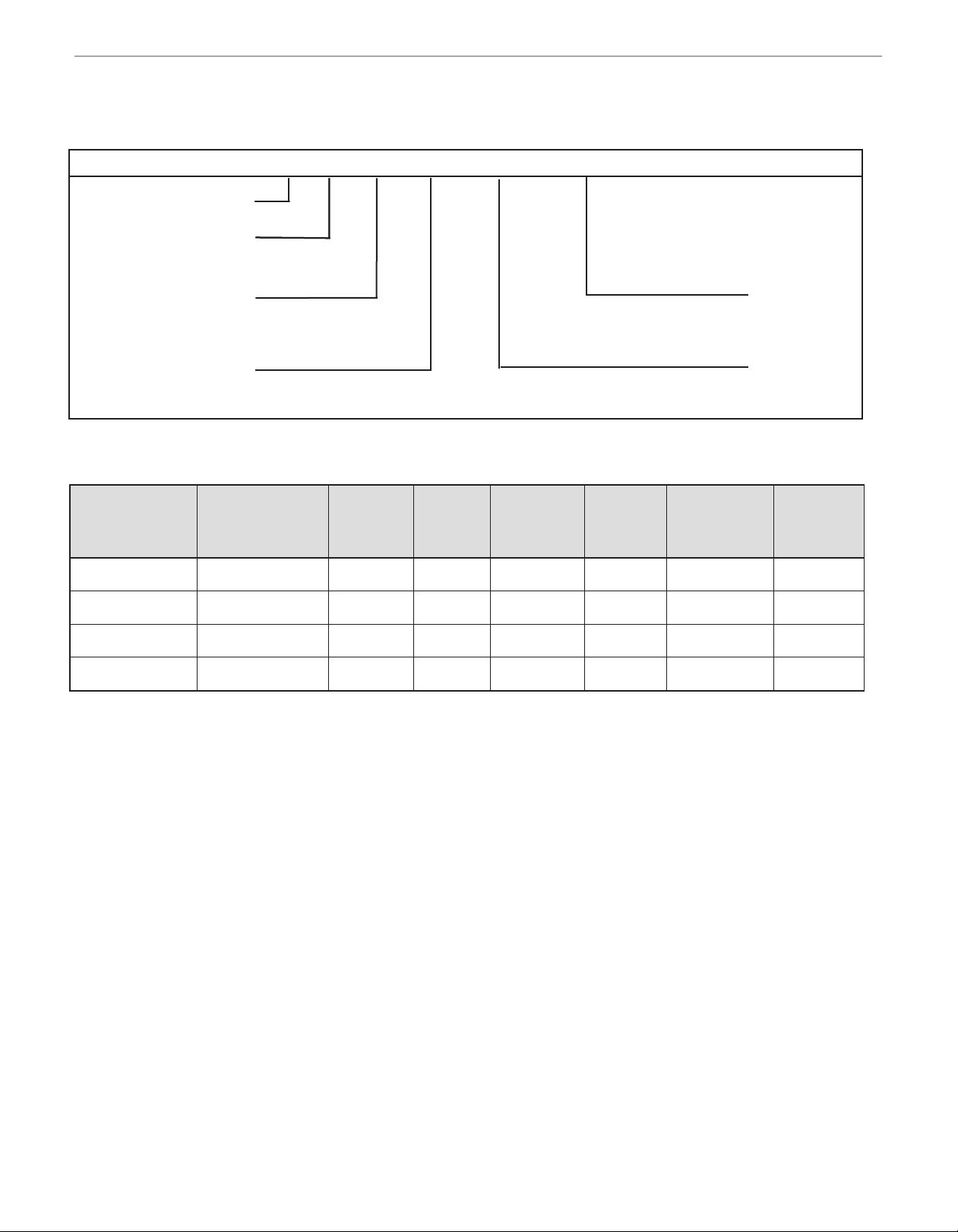
Model Number Guide
M MB V 08 B E
MRCOOL
MODULAR BLOWER
MOTOR TYPE
VARIABLE SPEED
CFM
08 = 800 CFM/2 Ton,
12 = 1200 CFM/3 Ton,
16 =1600 CFM/4 Ton,
20 = 2000 CFM/5 Ton)
P = PSC
E = ECM
CABINET SIZE
B = 17.5
C = 21
D = 24.5
Physical Data
Blower
Model Voltage/Phase/Hz
Motor
(hp)
MMBV08BE 208-230/1/60 1/3 * .40 2.4 1-1/2 - 2 79
MMBV12BE 208-230/1/60 1/2 * .40 3.1 1-1/2 -3 86
MMBV16CE 208-230/1/60 3/4 * .40 5.7 2 - 4 97
MMBV20DE 208-230/1/60 3/4 * .40 5.7 3 - 5 105
Blower
Motor
Speeds
Maximum
Duct
Static
Rated
Load
Amps
Nominal
Tonnage
Weight
(lbs.)
mrcool.com
Page 2
Page 3

ELECTRIC FURNACE MODULAR AIR SYSTEM MMBV*E
Electrical Data
Blower
Size
Electrical Heating Cap.
kW Btuh 208v 240v Amps per Stage
Blower
Amps
(2) (3) Total Amps per Circuit
Total Unit
Amps
MCA
Circuit Breaker
(1) 240v (1) 240v 208V 240V 1 2 3 1 2 3 208 240 208v 240v 1 2
08 (no heat) 0 0 2.6 2.4 --- --- --- --- --- --- 2.3 2.4 2.9 3.0 15 ---
08 5 17,100 2.6 2.4 20.7 --- --- 23.2 --- --- 20.7 23.2 25.8 29.0 30 --08 7.5 25,600 2.6 2.4 29.7 --- --- 33.7 --- --- 29.7 33.7 37.1 42.1 45 --08 10 34,100 2.6 2.4 38.7 --- --- 44.1 --- --- 37.7 44.1 48.4 55.1 60 ---
12 (no heat) 0 0 2.9 2.7 --- --- --- --- --- --- 2.9 2.7 3.6 3.4 15 ---
12 5 17,100 2.9 2.7 20.9 --- --- 23.5 --- --- 20.9 23.5 26.1 29.4 30 --12 7.5 25,600 2.9 2.7 30.0 --- --- 34.0 --- --- 30.0 34.0 37.5 42.5 45 --12 10 34,100 2.9 2.7 39.0 --- --- 44.4 --- --- 39.0 44.4 48.8 55.5 60 --12 15 51,200 2.9 2.7 39.0 18.1 --- 44.4 20.8 --- 57.1 65.2 71.4 81.5 60 30
16 (no heat) 0 0 3.8 3.5 --- --- --- --- --- --- 3.8 3.5 4.8 4.4 15 ---
16 10 34,100 3.8 3.5 39.9 --- --- 45.1 --- --- 39.9 45.1 49.9 56.4 60 --16 15 51,200 3.8 3.5 39.9 18.1 --- 45.1 20.8 --- 58.0 65.9 72.5 82.4 60 30
16 20 68,300 3.8 3.5 39.9 27.1 --- 45.1 41.7 --- 76.0 86.8 95.0 108.5 60 60
20 (no heat) 0 0 4.7 4.3 --- --- --- --- --- --- 0.0 0.0 0.0 0.0 15 ---
20 10 34,100 4.7 4.3 40.9 --- --- 45.9 --- --- 40.9 45.9 51.1 57.4 60 --20 15 51,200 4.7 4.3 40.9 18.1 --- 45.9 20.8 --- 59.0 66.7 73.8 83.4 60 30
20 20 68,300 4.7 4.3 40.9 36.1 --- 45.9 41.7 --- 77.0 87.6 96.3 109.5 60 60
NOTE:
If nominal CFM is 1000 (2.5 tons) with 15 kW electric heat, the motor speed must be set at medium or higher.
Maximum kW for units with nominal CFM set at 1400 (3.5 tons) is 15 kW.
For 208 volt use .751 correction factor for kW and Btuh.
15 and 20 kW (2 stage models) require 2 supply circuits.
Circuit #1 includes blower motor amps.
kW packages in bold indicate that these packages require and include circuite breakers. Optional for others.
Accessories
Kit Number Description Used with
MHK05B 5kW with Circuit Breaker 8, 12
MHK07B 7.5kW with Circuit Breaker 8, 12
MHK10B 10kW with Circuit Breaker All
MHK15B 15kW with Circuitl Breaker
MHK20B
*C - Constant or V - Variable
1 N = No circuit breaker
1 C = Circuit breaker
20kW with Circuitl Breaker
mrcool.com
Page 3
12, 16, 20
Page 4

ELECTRIC FURNACE MODULAR AIR SYSTEM MMBV*E
Blower Performance
Air
Handler
Model
MMBV08BE
MMBV12BE
MMBV16CE
Energized
Thermostat
Terminal
Y1
Y1 / Y2
G
Y1
Y1 / Y2
G
Y1
Y1 / Y2
G
Control
CFM @ ESP. in W.C.
Board
Tap
A 710 690 680 690 690 690 690 690
B 560 560 560 570 560 560 570 570
C 490 490 500 500 500 500 490 490
D 430 430 430 430 440 440 440 440
A 1010 980 970 980 980 980 980 970
B 800 800 800 810 800 800 810 810
C 700 700 710 710 710 710 700 700
D 610 610 620 620 630 630 630 630
A 510 490 480 490 490 490 490 490
B 400 400 400 410 400 400 410 410
C 350 350 360 360 360 360 350 350
D 310 310 310 310 320 320 320 320
A 850 860 860 870 880 880 880 880
B 710 720 730 740 740 750 730 730
C 620 600 600 600 610 600 610 610
D 500 480 470 470 460 450 440 420
A 1,220 1,220 1,210 1,210 1,210 1,210 1,200 1,200
B 1,000 1,010 1,040 1,040 1,040 1,040 1,040 1,020
C 820 820 830 830 840 840 840 840
D 650 640 640 650 650 660 660 640
A 640 620 640 640 640 640 630 630
B 570 560 560 550 560 550 520 520
C 510 500 490 480 470 460 440 430
D 470 450 440 410 400 400 390 380
A 1,130 1,120 1,120 1,110 1,100 1,090 1,080 1,070
B 990 970 960 950 940 920 910 910
C 850 830 810 790 780 750 740 710
D 690 660 650 620 610 580 560 530
A 1,680 1,660 1,640 1,620 1,610 1,610 1,610 1,600
B 1,440 1,400 1,400 1,400 1,390 1,380 1,380 1,360
C 1,230 1,220 1,210 1,210 1,200 1,180 1,170 1,160
D 1,000 990 980 980 960 950 950 940
A 800 790 760 750 720 710 680 660
B 680 670 650 630 610 580 550 520
C 580 540 510 480 460 430 390 370
D 480 430 390 410 400 400 400 400
.10 .20 .30 .40 .50 .60 .70 .80
mrcool.com
Page 4
Page 5

ELECTRIC FURNACE MODULAR AIR SYSTEM MMBV*E
Blower Performance
Air
Handler
Model
MMBV20DE
Notes: Humidistat will reduce colling airflow by 10% in high humidity.
Energized
Thermostat
Terminal
Y1
Y1 / Y2
G
Adjust tap (+) will increase airflow by 10%, while tap (-) will decrease airflow by 12%
Adjust tap test will cause the motor to run at 70% of full airflow. Use this for troubleshooting only.
At the start of a call for cooling, there is a blower delay of 1 minute.
Control
Board
Tap
A 1,250 1,230 1,210 1,180 1,140 1,100 1,070 1,050
B 1,120 1,100 1,080 1,040 990 970 940 930
C 980 950 900 860 840 820 810 800
D 860 810 760 740 720 710 700 680
A 1,840 1,830 1,810 1,790 1,780 1,760 1,730 1,690
B 1,640 1,640 1,620 1,610 1,600 1,570 1,540 1,490
C 1,390 1,380 1,370 1,360 1,322 1,296 1,255 1,220
D 1,210 1,190 1,180 1,140 1,100 1,040 1,030 1,000
A 910 870 830 790 770 760 740 730
B 840 790 740 710 710 690 680 660
C 740 690 640 640 620 610 600 590
D 680 610 580 570 560 550 530 500
Dimensions (in.)
Unit
Size
A B C
Supply Duct Opening Return Duct Opening
Depth Width Depth Width
CFM @ ESP. in W.C.
.10 .20 .30 .40 .50 .60 .70 .80
MMBV08BE 25 21 17-1/2 16-1/2 15-1/2 19-1/2 16
MMBV12BE 25 21 17-1/2 16-1/2 15-1/2 19-1/2 16
MMBV16CE 26 21 21 16-1/2 19 19-1/2 19-1/2
MMBV20DE 26 21 24-1/2 16-1/2 22-1/2 19-1/2 23
Optional line voltage on top or right side of blower.
C
All specications and illustrations
subject to change without notice
and without incurring obligations.
mrcool.com
Page 5
 Loading...