

The Signature Series is NOT designed for amateur installation. Installation SHOULD be performed by an authorized technician.
Please read this manual carefully before installation and keep it for future reference.
Installation Manual
Signature Series
MHP15*A HEAT PUMP SPLIT SYSTEM
The Signature Series is NOT designed for amateur installation. Installation SHOULD be performed by an authorized technician.
Please read this manual carefully before installation and keep it for future reference.
INSTALLATION INSTRUCTIONS
MHP15*A HEAT PUMP SPLIT SYSTEM
(R410A REFRIGERANT)
This manual must be left with the homeowner for future reference.
This is a safety alert symbol and should never be ignored. When you see this symbol on labels or in
manuals, be alert to the potential for personal injury or death.
Table of Contents
Safety Precautions ......................................................2
Installation ...................................................................2
Electrical Connections.................................................5
Start-Up Procedure......................................................6
Operation.....................................................................7
Homeowner’s Information .........................................10
NOTE TO INSTALLING DEALER
These instructions and warranty are to be given to the
owner or displayed near the indoor air handler unit.
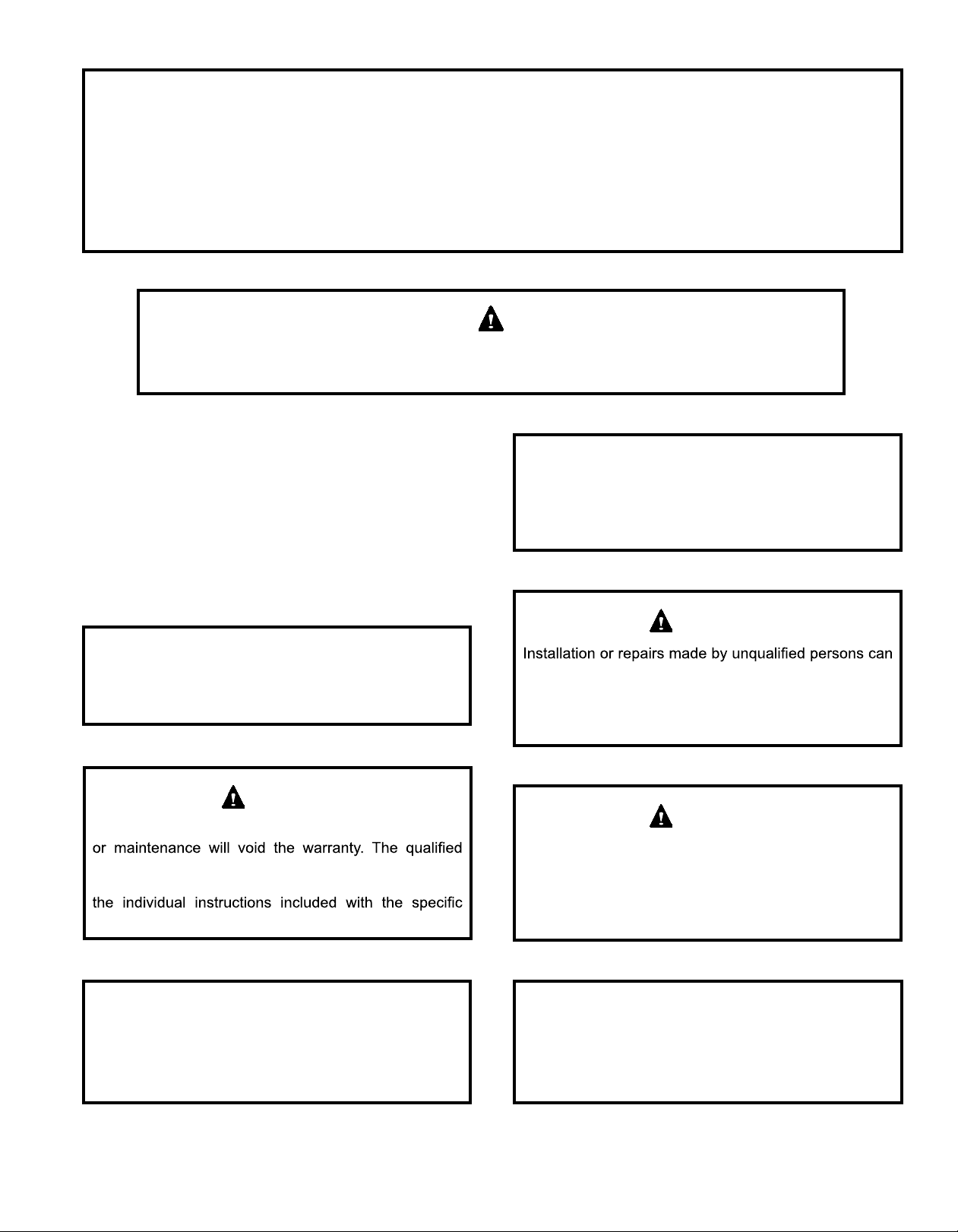
CAUTION
Improper installation, adjustment, alteration, service
installer or agency must use factory-authorized kits
or accessories when added to this products. Refer to
accessory kit.
NOTE
These instructions are intended as a general guide and
do not supersede national, state or local codes in any
way.
WARNING
result in hazards to you and others. Installation MUST
conform with local building codes and with the National
Electrical Code NFPA 70/ANSI C1-1993 or current
edition and Canadian Electrical Code Part 1 CSA C22.1.
WARNING
Before installing, modifying, or servicing system, main
electrical disconnect switch must be in the OFF position.
There may be more than 1 disconnect switch. Lock out
and tag switch with a suitable warning label. Electrical
shock can cause personal injury or death.
Manufactured By
MRCOOL, LLC
Hickory, KY 42051
*P506318-03C*
(P) 506318-03C
Save these instructions for future reference
Page 1 of 11506318-03C mrcool.com
These units are designed for use in residential and
light commercial type buildings. Heat Pumps may only
be installed with indoor combinations listed in the Air
Conditioning, Heating and Refrigeration Institute (AHRI)
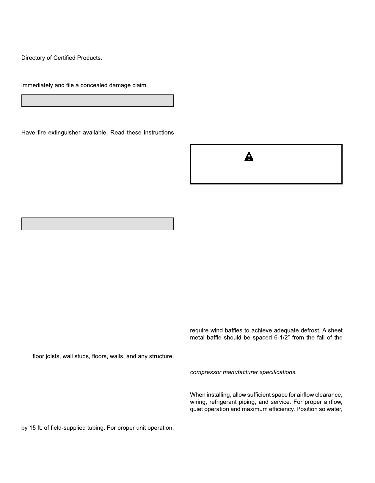
Inspect the unit for any damage before installation. If
damage is found, notify the transportation company
Safety Precautions
Follow all safety codes. Wear safety glasses and work
gloves. Use quenching cloth for brazing operations.
NOTE: Maximum liquid-line size is 3/8 in. O.D. for all
residential applications including long lines.
Outdoor Section
Zoning ordinances may govern the minimum distance the
condensing unit can be installed from the property line.
Install on a Solid, Level Mounting Pad
The outdoor section is to be installed on a solid foundation.
This foundation should extend a minimum of 2” (inches)
beyond the sides of the outdoor section. To reduce the
possibility of noise transmission, the foundation slab
should NOT be in contact with or be an integral part of the
building foundation.
thoroughly and follow all warning or cautions attached to
the unit.
1. Always wear proper personal protection equipment.
2. Always disconnect electrical power before removing
panel or servicing equipment.
3. Keep hands and clothing away from moving parts.
4. Handle refrigerant with caution, refer to proper MSDS
from refrigerant supplier.
5. Use care when lifting, avoid contact with sharp edges.
Installation
NOTE: In some cases noise in the living area has been
traced to gas pulsations from improper installation of
equipment.
1. Locate unit away form windows, patios, decks, etc.
where unit operation sounds may disturb customer.
2. Ensure that vapor and liquid tube diameters are
appropriate to capacity of unit.
3. Run refrigerant tubes as directly as possible by
avoiding unnecessary turns and bends.
4. Leave some slack between structure and unit to
absorb vibration.
5. When passing refrigerant tubes through the wall, seal
opening with RTV or other silicon-based caulk.
6. Avoid direct tubing contact with water pipes, duct work,
Elevate Unit
CAUTION
Accumulation of water and ice in base pan may cause
equipment damage.
Elevate unit per local climate and code requirements to
provide clearance above estimated snowfall level and
ensure adequate drainage of unit. Use snow stand in areas
where prolonged freezing temperatures are encountered.
If conditions or local codes require the unit be attached to
pad or mounting frame, tie down bolts should be used and
fastened through knockouts provided in unit base pan.
Rooftop Installations
Mount on level platform or frame 6 inches above roof
surface. Place unit above a load-bearing wall and isolate
unit and tubing set from structure. Arrange supporting
members to adequately support unit and minimize
transmission of vibration to building. Ensure roof structure
and anchoring method is adequate for location. Consult
local codes governing rooftop applications.
Roof mounted units exposed to winds above 5 mph may
coil. The height should cover the face of the coil and the
length should be 6” from the access panel.
7. Do not suspend refrigerant tubing from joists and
studs with a rigid wire or strap which comes in direct
contact with tubing.
8. Ensure that tubing insulation is pliable and completely
surrounds vapor tube.
When outdoor unit is connected to factory-approved indoor
unit, outdoor unit contains system refrigerant charge for
operation with indoor unit of the same size when connected
check refrigerant charge using charging information
located on control box cover.
NOTE: Unit must be level to within ± 1/4 in./ft. per
Clearance Requirements
snow, or ice from roof or eaves cannot fall directly on unit.
506318-03CPage 2 of 11 mrcool.com
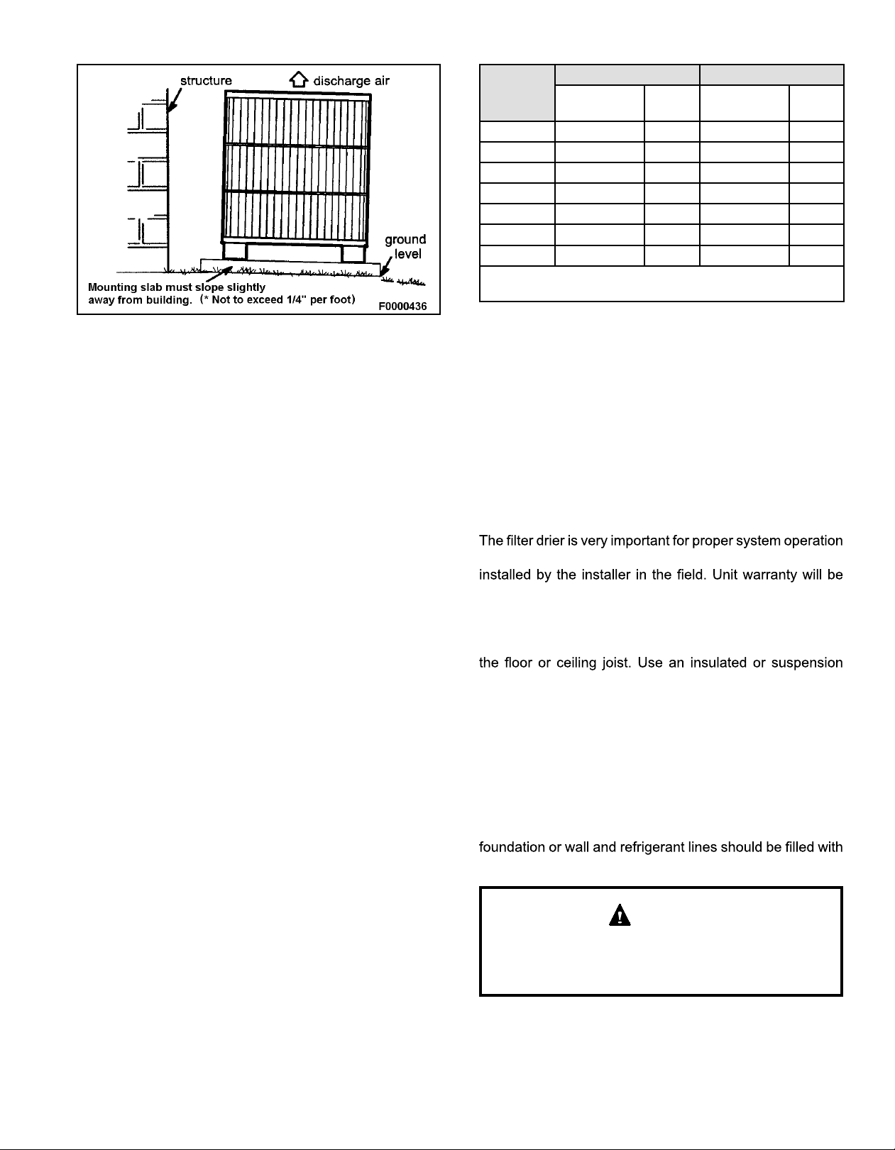
Figure 1.
Liquid Vapor
Capacity
-018 3/8” 3/8” 3/4” 3/4”
-024 3/8” 3/8” 3/4” 3/4”
-030 3/8” 3/8” 3/4” 3/4”
-036 3/8” 3/8” 7/8” 7/8”
-042 3/8” 3/8” 7/8” 7/8”
-048 3/8” 3/8” 7/8” 7/8”
-060 3/8” 3/8” 7/8” *1-1/8”
* Field supplied 7/8 x 1-1/8 connector required on both ends
of vapor tubing.
Connections
Dia.
Tube
Dia.
Connections
Dia.
Tube
Dia.
Table 1. Recommended Liquid & Vapor Tube
Diameters (in.)
DO LOCATE THE UNIT:
• With proper clearances on sides and top of unit
• On a solid, level foundation or pad
• To minimize refrigerant line lengths
DO NOT LOCATE THE UNIT:
• On brick, concrete blocks or unstable surfaces
• Near clothes dryer exhaust vents
• Near sleeping area or near windows
• Under eaves where water, snow or ice can fall directly
on the unit
• With clearance less than 2 ft. from a second unit
• With clearance less than 4 ft. on top of unit
Operating Ambient
The minimum outdoor operating ambient in cooling mode
is 55°F, and the maximum outdoor operating ambient in
cooling mode is 125°F. The maximum outdoor operating
ambient in heating mode is 66°F.
Refrigeration Line Sets
Use only refrigerant grade copper tubes. Split systems
may be installed with up to 50 feet of line set (no more than
20 feet vertical) without special consideration (see long
line set guidelines).
Be extra careful with sharp bends. Tubing can “kink” very
easily, and if this occurs, the entire tube length will have
to be replaced. Extra care at this time will eliminate future
service problems.
It is recommended that vertical suction risers not be upsized. Proper oil return to the compressor should be
maintained with suction gas velocity.
Filter Drier
and reliability. If the drier is shipped loose, it must be
void, if the drier is not installed.
Installation of Line Sets
DO NOT fasten liquid or suction lines in direct contact with
type of hanger. Keep both lines separate, and always
insulate the suction line. Long liquid line runs (30 feet or
more) in an attic will require insulation. Route refrigeration
line sets to minimize length.
DO NOT let refrigerant lines come in direct contact with
foundation. When running refrigerant lines through the
foundation or wall, openings should allow for a sound
and vibration absorbing material to be placed or installed
between tubing and foundation. Any gap between
It is important that no tubing be cut or seals broken until you
are ready to actually make connections to the evaporator
and to the condenser section. DO NOT remove rubber
plugs or copper caps from the tube ends until ready to
make connections at evaporator and condenser. Under no
circumstances leave the lines open to the atmosphere for
any period of time, if so unit requires additional evacuation
to remove moisture.
a vibration damping material.
CAUTION
If ANY refrigerant tubing is required to be buried by state
or local codes, provide a 6 inch vertical rise at service
valve.
Page 3 of 11506318-03C mrcool.com
 Loading...