

Page 1

The Signature Series is NOT designed for amateur installation. Installation SHOULD be performed by an authorized technician.
Please read this manual carefully before installation and keep it for future reference.
Owner & Installation
Manual
Signature Series
MGM*95SE*XA Gas Furnace
The Signature Series is NOT designed for amateur installation. Installation SHOULD be performed by an authorized technician.
Please read this manual carefully before installation and keep it for future reference.
Page 2
Gas Furnace
INSTALLATION INSTRUCTIONS
MGM*95SE*XA
Warm Air Gas Furnace
This manual must be left with the homeowner for future reference.
Table of Contents
2
3
Gas Piping 38
WARNING
MRCOOL, LLC
13
13
16
6
6
9
CAUTION
50
52
55
56
*F507276-C*
(P) 507276-05C
Save these instructions for future reference
507276-05C Page 1 of 57mrcool.com
Page 3
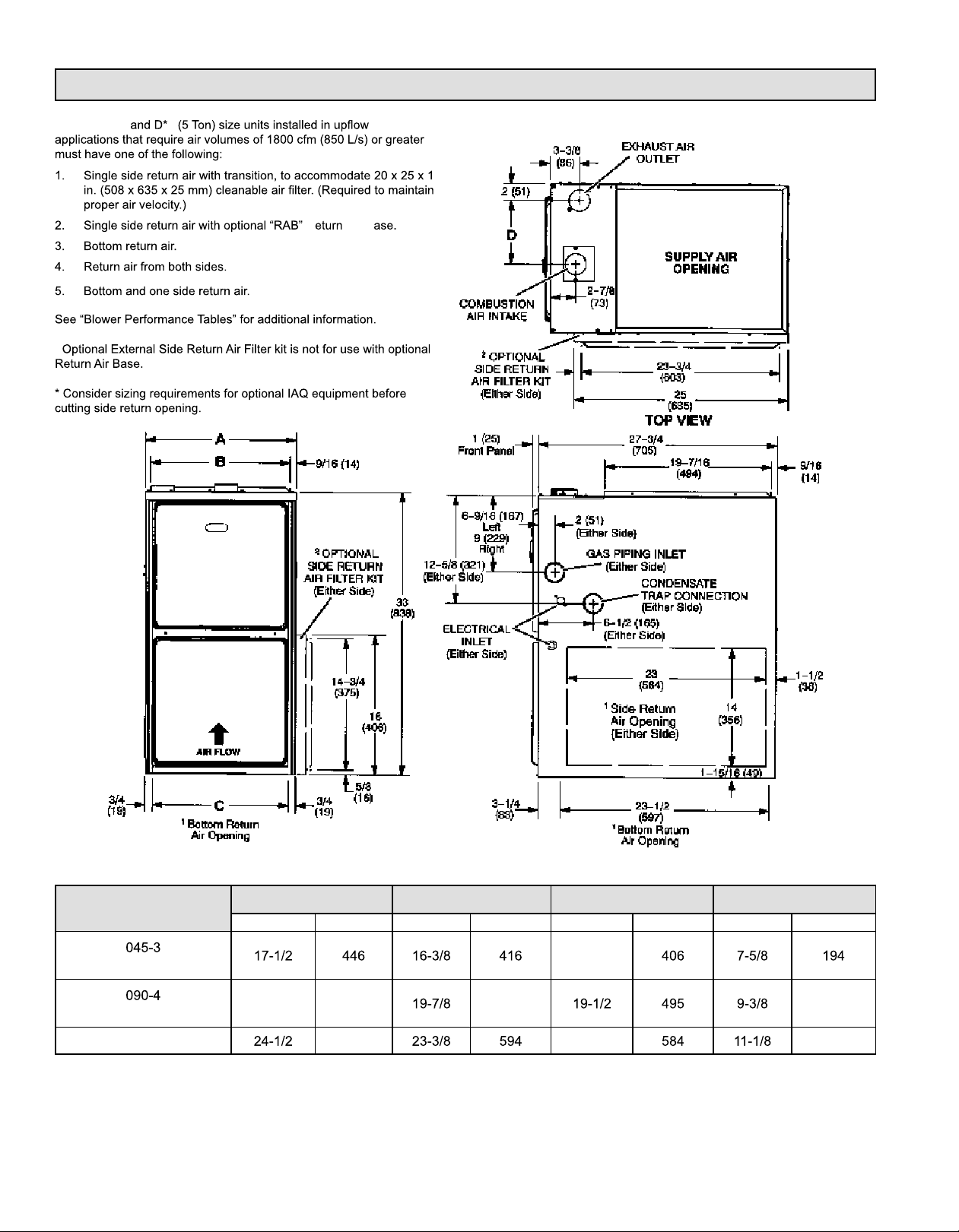
Unit Dimensions
1
NOTE - C*5 5
2
R Air B
Model
070-3
110-5
135-5
FRONT VIEW SIDE VIEW
A B C D
in. mm in. mm in. mm in. mm
16
21 533
622 23 283
505 238
507276-05CPage 2 of 57 mrcool.com
Page 4
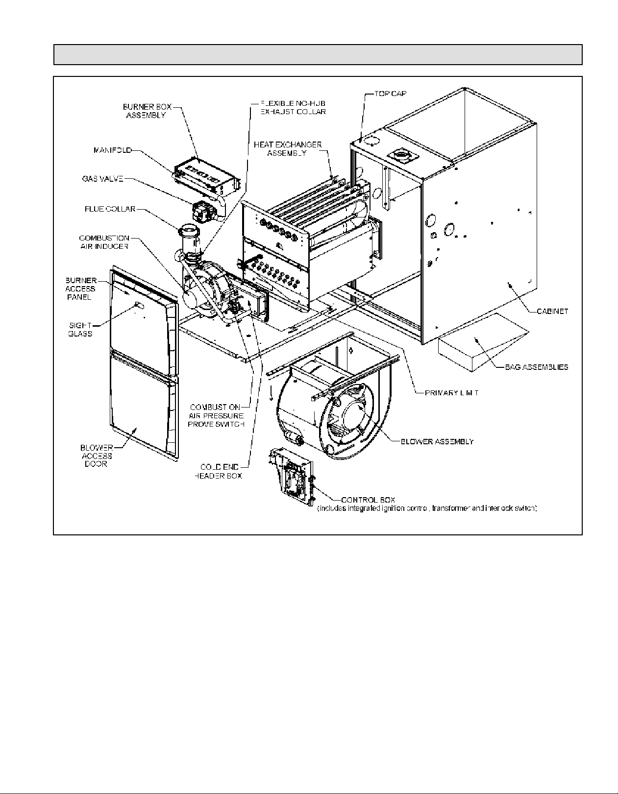
Parts Arrangement
Figure 1.
507276-05C Page 3 of 57mrcool.com
Page 5
Gas Furnace
MG*95SE*XA
MG*95SE*XA
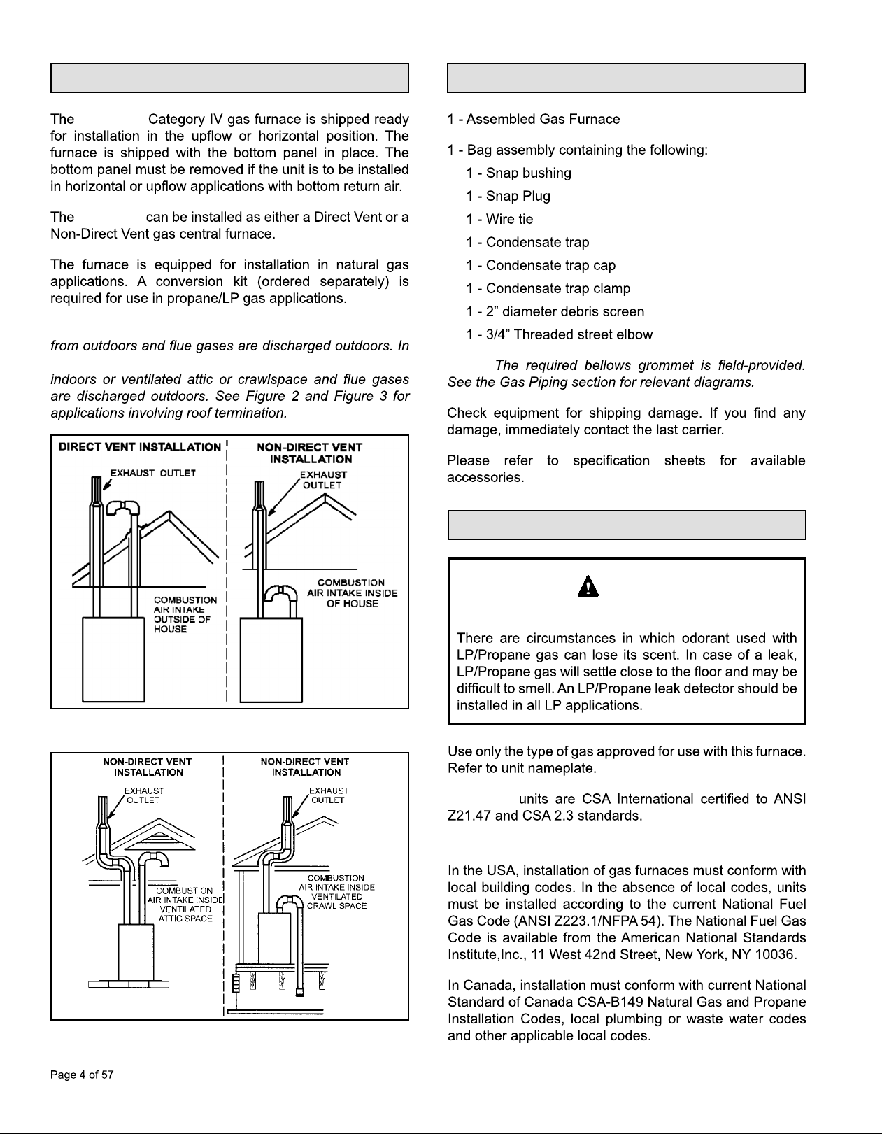
NOTE: In Direct Vent installations, combustion air is taken
Shipping and Packing List
Non-Direct Vent installations, combustion air is taken from
Figure 2.
NOTE:
Safety Information
DANGER
DANGER OF EXPLOSION!
Figure 3.
MG*95SE*XA
Building Codes
507276-05Cmrcool.com
Page 6
Installation Locations
NOTE:
NOTE:
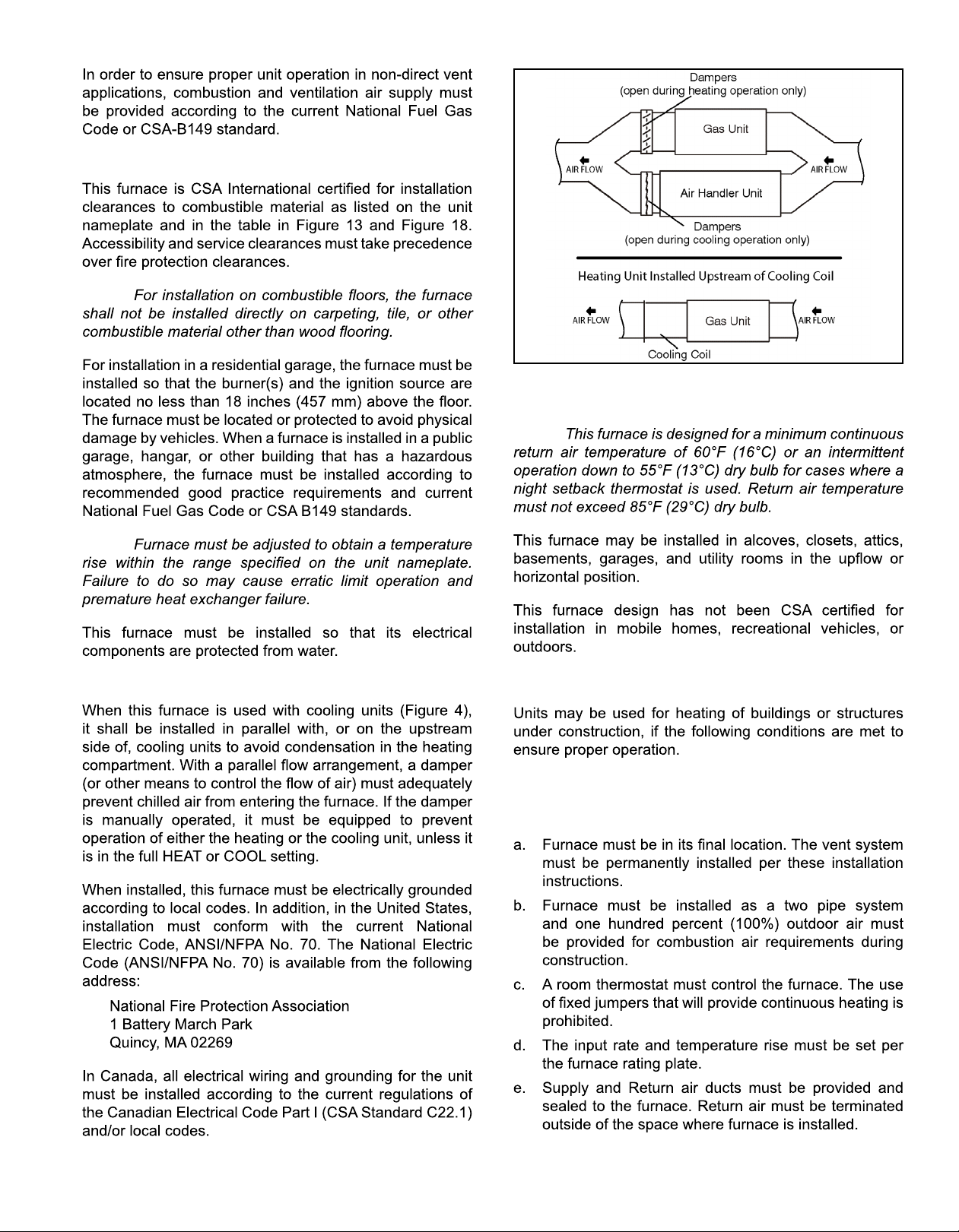
Figure 4. Heating Unit Installed Parallel to Air Handler
Unit
NOTE:
Installed in Combination with a Cooling Coil
Use of Furnace as a Construction Heater
DO NOT USE THE UNIT FOR CONSTRUCTION HEAT
UNLESS ALL OF THE FOLLOWING CRITERIA ARE
MET:
507276-05C Page 5 of 57mrcool.com
Page 7
COMPONENT FAILURE AS A RESULT OF FAILURE TO
•
•
NOTE:
•
•
•
CAUTION
General
•
Combustion, Dilution & Ventilation Air
NOTE: In Non-Direct Vent Installations, combustion air is
•
•
507276-05CPage 6 of 57 mrcool.com
Page 8
WARNING
•
•
•
•
•
•
•
•
•
•
•
•
•
CAUTION
Air from Inside
507276-05C Page 7 of 57mrcool.com
Page 9
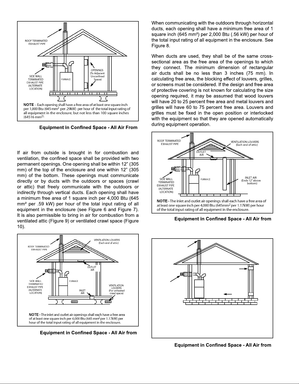
Figure 5.
Air from Outside
Inside
Figure 7.
ROOF TERMINATED
EXHAUST PIPE
Outside
(All Air through Ventilated Attic)
Figure 6.
Outside
(Inlet Air from Crawl Space and Outlet Air to
Ventilated Attic)
OUTLET AIR
SIDE WALL
TERMINATED
EXHAUST PIPE
(ALTERNATE
LOCATION)
NOTE−Each air duct opening shall have a free area of at least one
square inch per 2,000 Btu (645mm
input rating of all equipment in the enclosure. If the equipment room
is located against an outside wall and the air openings communicate directly with the outdoors, each opening shall have a free area
of at least 1 square inch per 4,000 Btu (645mm
hour of the total input rating of all other equipment in the enclosure.
FURNACE
INLET AIR
2
per .59kW) per hour of the total
2
per 1.17kW) per
Figure 8.
Outside
507276-05CPage 8 of 57 mrcool.com
Page 10
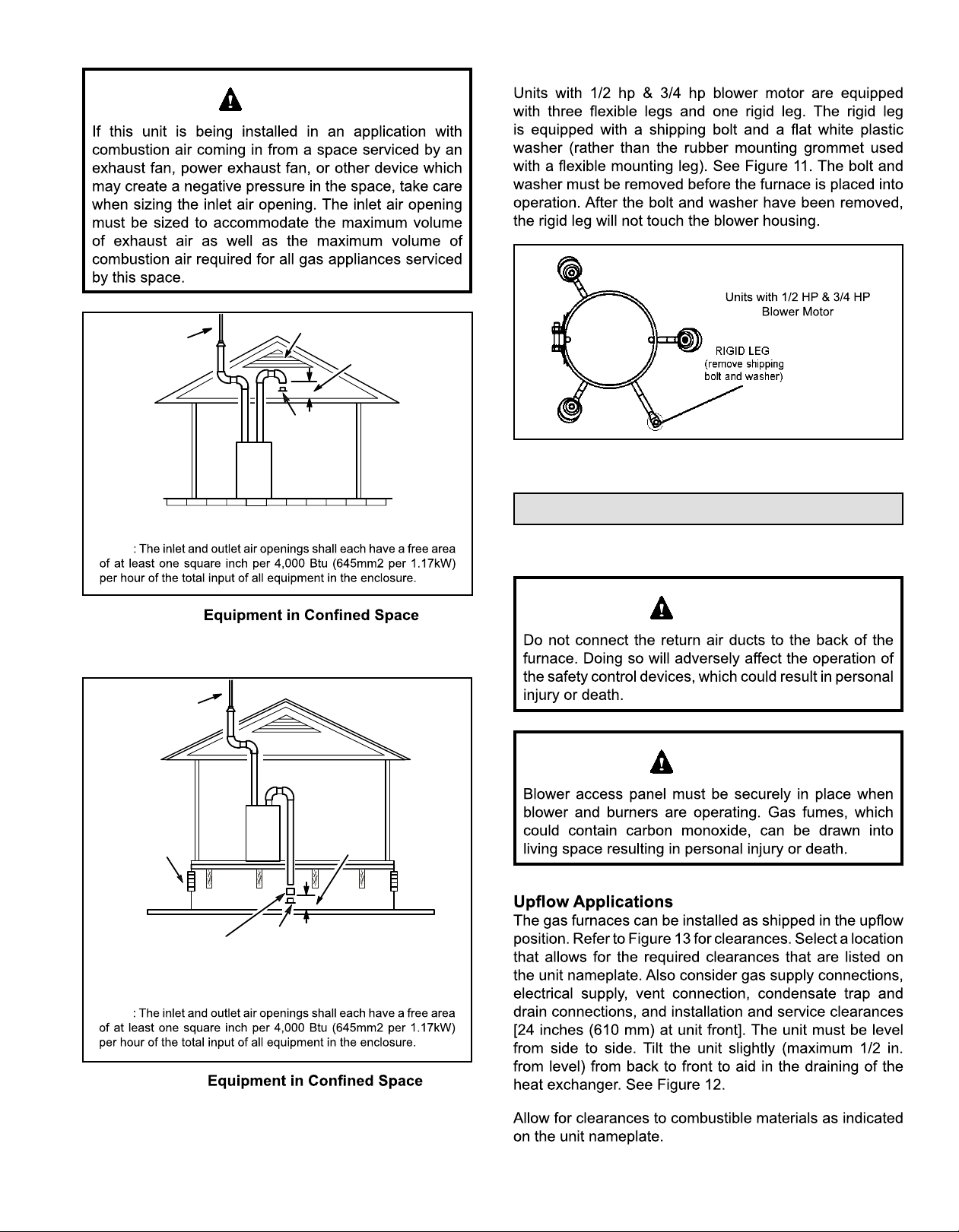
WARNING
Shipping Bolt Removal
Roof Terminated
Exhaust Pipe
Ventilation Louvers
*Intake Debris
Screen
(Provided)
Furnace
Inlet Air
(Minimum 12 in.
(305mm) above
Attic Floor)
* See Maximum Vent Lengths table
NOTE
Figure 9.
(Inlet Air from Ventilated Attic and Outlet Air to
Outside)
Roof Terminated
Exhaust Pipe
Figure 11.
Installation
Setting Equipment
WARNING
Inlet Air
Minimum
Ventilation
Louvers
(Crawl Space)
Coupling or
3 in. to 2 in.
Transition
(Field Provided)
Furnace
12 in. (305mm)
above Crawl
Space Floor
*Intake Debris Screen Provided
* See Maximum Vent Lengths table
NOTE
Figure 10.
(Inlet Air from Ventilated Crawl Space and Outlet Air
to Outside)
507276-05C Page 9 of 57mrcool.com
WARNING
Page 11
WARNING
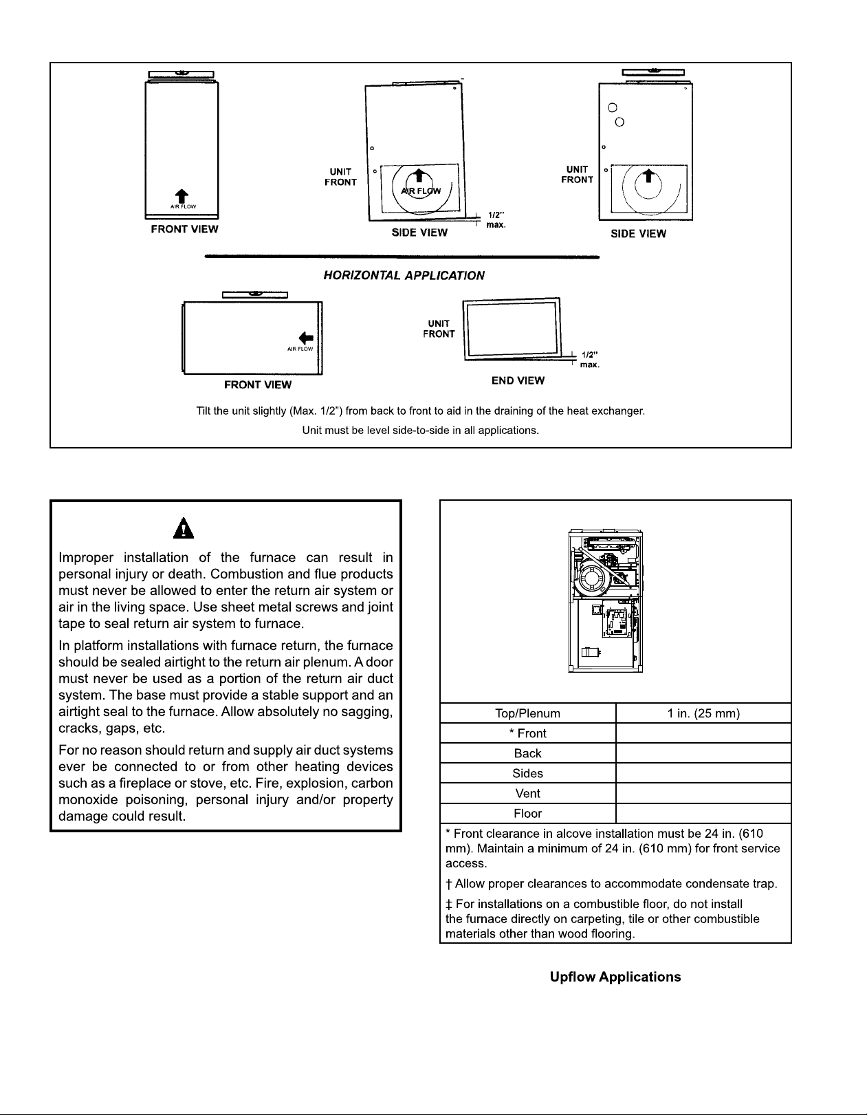
Figure 12. Setting Equipment
Top
Left Side
Right Side
Bottom (Floor)
Top/Plenum 1 in. (25 mm)
*Front 0
Back 0
Sides 0†
Vent 0
Floor 0‡
*Front clearance in alcove installation must be 24 in. (610 mm).
Maintain a minimum of 24 in. (610 mm) for front service access.
†Allow proper clearances to accommodate condensate trap.
‡For installations on a combustible
on carpeting, tile or other combustible materials other than wood
ooring.
oor, do not install the furnace directly
0
0
0†
0
0‡
Figure 13. Installation Clearances
507276-05CPage 10 of 57 mrcool.com
Page 12
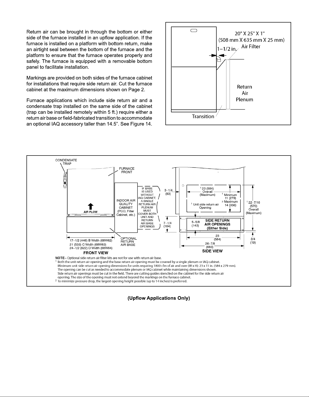
Return Air Guidelines
Figure 14. Side Return Air
(with Transition and Filter)
Figure 15. Optional Return Air Base
507276-05C Page 11 of 57mrcool.com
Page 13
Right−Hand Discharge
dnEthgiRdnEtfeL
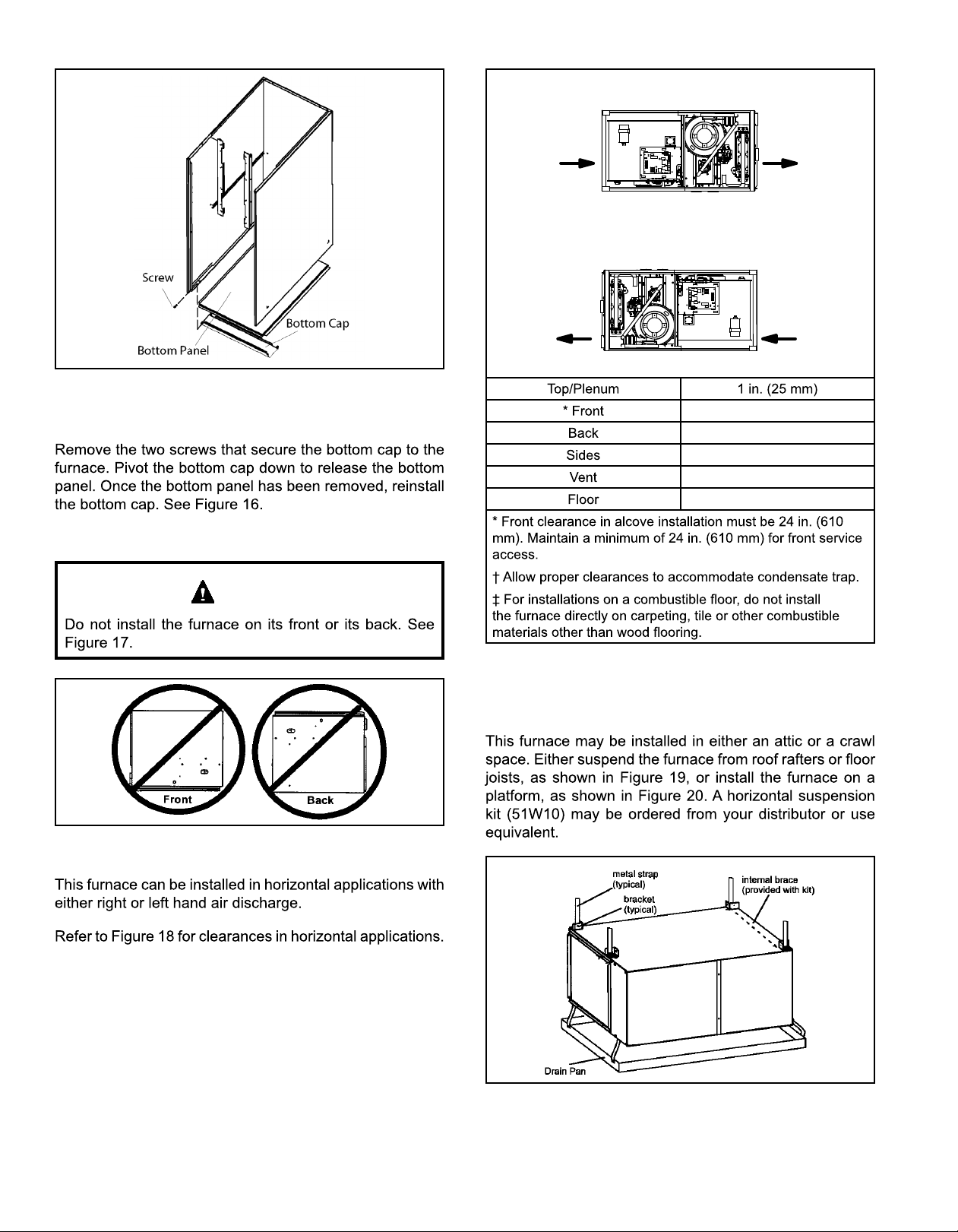
Figure 16. Removing the Bottom Panel
Removing the Bottom Panel
Horizontal Applications
WARNING
Air
Flow
Air
Flow
Bottom (Floor)**
Left−Hand Discharge
Top
dnEthgiRdnEtfeL
Air
Flow
Air
Flow
Bottom (Floor)**
Top 0
Front* 0
Back 0
Ends 0
Vent 0
Floor 0‡
* Front clearance in alcove installation must be 24 in. (610 mm).
Maintain a minimum of 24 in. (610 mm) for front service access.
**An 8" service clearance must be maintained below the unit to provide
for servicing of the condensate trap.
‡For installations on a combustible
on carpeting, tile or other combustible materials other than wood
ooring.
oor, do not install the furnace directly
0
0
0†
0
0‡
Figure 17.
Figure 18. Installation Clearances
Horizontal Applications
Suspended Installation of Horizontal Unit
Figure 19. Typical Horizontal Application
507276-05CPage 12 of 57 mrcool.com
Page 14
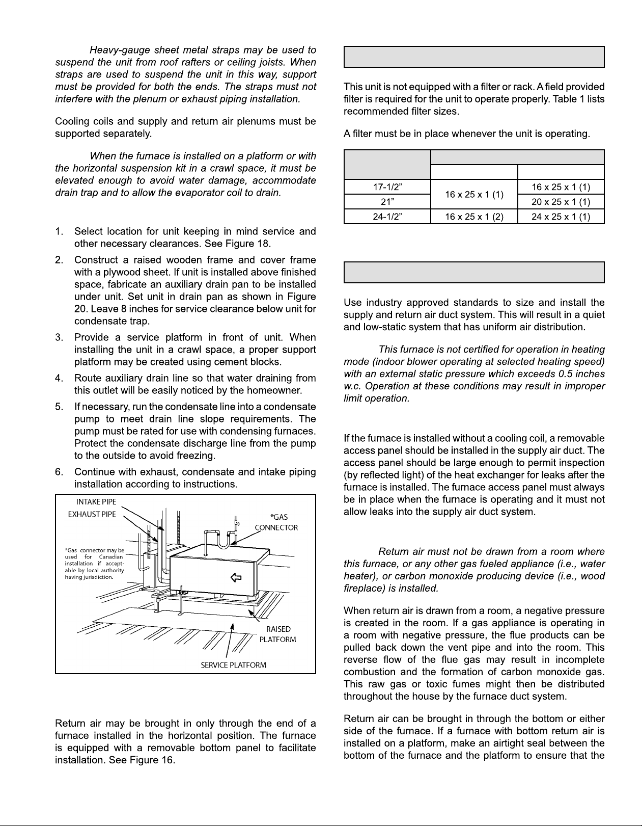
NOTE:
Filters
NOTE:
Platform Installation of Horizontal Unit
Furnace Cabinet
Width
Duct System
NOTE:
Supply Air Plenum
Filter Size
Side Return Bottom Return
Table 1.
Figure 20.
Return Air - Horizontal Applications
507276-05C Page 13 of 57mrcool.com
Return Air Plenum
NOTE:
Page 15
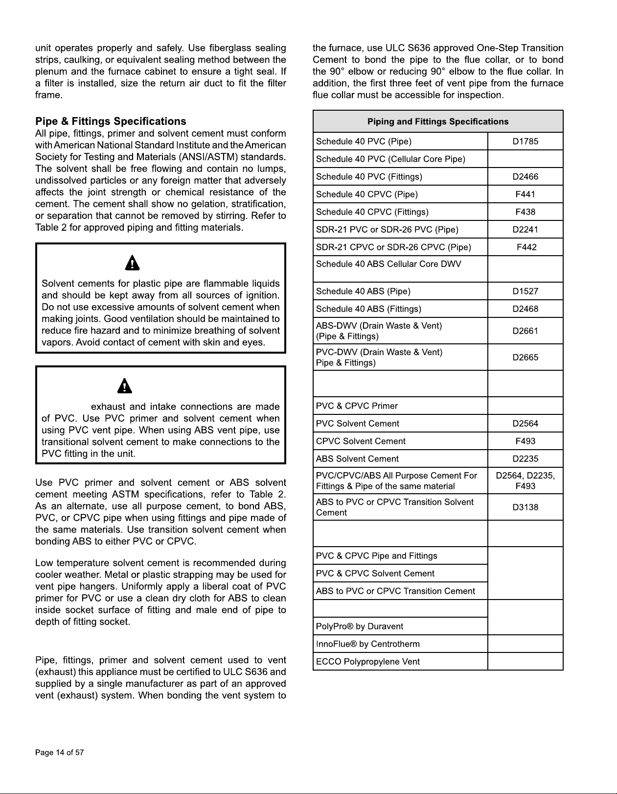
F891
MGM95*E
CAUTION
IMPORTANT
(Pipe)
PRIMER & SOLVENT CEMENT
CANADA PIPE & FITTING & SOLVENT
CEMENT
F628
ASTM
SPECIFICATION
F656
MARKING
Canadian Applications Only
POLYPROPYLENE VENTING SYSTEM
TM
Table 2.
ULCS636
ULC-S636
ULC-S636
ULC-S636
507276-05Cmrcool.com
Page 16
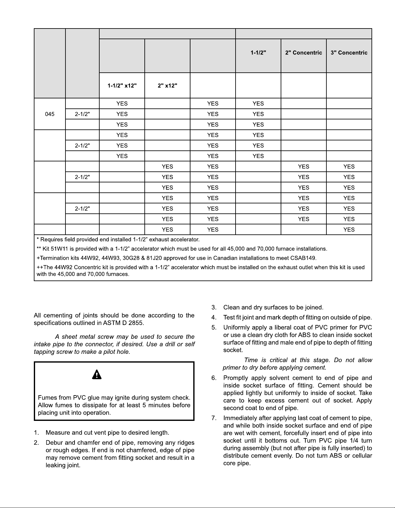
STANDARD CONCENTRIC
Capacity
070
090
110
135 3
VENT
PIPE DIA.
(in.)
2
3
2
3
2
3
2
3
Outdoor
Exhaust
Accelerator
(Dia. X Length)
Outdoor
Exhaust
Accelerator
(Dia. X Length)
Flush Mount
Kit
51W11**
Concentric Kit Kit Kit
71M80
OR
+44W92++
69M29
OR
+44W92++
60L46
OR
44W93+
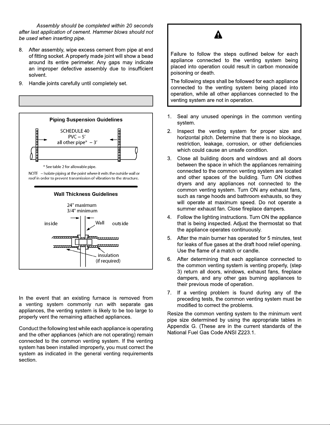
Joint Cementing Procedure
NOTE:
DANGER
DANGER OF EXPLOSION!
Table 3. Outdoor Termination Kits Usage
NOTE:
507276-05C Page 15 of 57mrcool.com
Page 17
NOTE:
Venting Practices
WARNING
CARBON MONOXIDE POISONING HAZARD
Figure 21.
Removal of the Furnace from Common Vent
507276-05CPage 16 of 57 mrcool.com
Page 18
CHIMNEY
OR GAS
VENT
(Check sizing
for remaining
appliance)
REPLACING FURNACE THAT
Vent Piping Guidelines
WAS PART OF A COMMON
VENT SYSTEM
NOTE: In non-Direct Vent installations, combustion air is
In Direct Vent installations, combustion air is taken from
FURNACE
(Removed from
from common
vent system)
If this gas furnace replaces a furnace which
was commonly vented with another gas appliance,
the size of the existing vent pipe for that gas
appliance must be checked. Without the heat of the
original furnace flue products, the existing vent pipe
is probably oversized for the single water heater or
other appliance. The vent should be checked for
proper draw with the remaining appliance.
Exhaust Piping
WATER
HEATER
Figure 22.
OPENINGS
(ToAdjacent
Room)
MRCOOL, LLC
NOTE:
NOTE:
CAUTION
CAUTION
507276-05C Page 17 of 57mrcool.com
Figure 23.
Page 19

IMPORTANT
Capacity Min. Vent Length*
Furnace capacity?
1
045, 070,
090, 110,
135
135 **
Table 4.
Which termination?
2
Which needs most
3
elbows?
How many?
4
Desired pipe size?
5
Standard or
Concentric?
See Table 3
Intake or
Exhaust?
2”, 2-1/2”
or 3”
What is the altitude?
6
Use Table 5 to find
7
max pipe length.
Figure 24.
507276-05CPage 18 of 57 mrcool.com
Page 20

MG*M95SE*XA Maximum Allowable Intake or Exhaust Vent Length in Feet
Number
of 90°
Elbows
Used
10 31 16 65 50 18 87 87 68 68
Number
of 90°
Elbows
Used
10 31 16 65 50 18 87 87 68 68
045 070 090 110 135 045 070 090 110 135 045 070 090 110 135 045 070 090 110 135
1 25 20
2 20 15 71 56
3 15 10 66 51 29 9 100 85 53 28 122 122 103 103 99
10 61 95 80 23 117 117 98 98
5 56 19 90 75 18 112 112 93 93 89
6 51 36
7 31 9 80 65 33 8 102 102 83 83 79
8
9 36 21 70 55 23 92 92 73 73 69
045 070 090 110 135 045 070 090 110 135 045 070 090 110 135 045 070 090 110 135
1 25 20
2 20 15 71 56
3 15 10 66 51 29 100 85 53 28 122 122 103 103 99
10 61 95 80 23 117 117 98 98
5 56 19 90 75 18 112 112 93 93 89
6 51 36
7 31 9 80 65 33 8 102 102 83 83 79
8
9 36 21 70 55 23 92 92 73 73 69
Capacity Capacity Capacity Capacity
76 61 39 19 110 95 63 38 132 132 113 113 109
105 90 58 33 127 127 108 108
85 70 38 13 107 107 88 88
26 75 60 28 97 97 78 78
Capacity Capacity Capacity Capacity
76 61 39 110 95 63 38 132 132 113 113 109
105 90 58 33 127 127 108 108
85 70 38 13 107 107 88 88
26 75 60 28 97 97 78 78
Table 5A.
507276-05C Page 19 of 57mrcool.com
Page 21

MG*M95SE*XA
Maximum Allowable Intake or Exhaust Vent Length in Feet
Number
of 90°
Elbows
Used
10 23 8 55
Number
of 90°
Elbows
Used
10 23 8 55
045 070 090 110 135 045 070 090 110 135 045 070 090 110 135 045 070 090 110 135
1 25 20
2 20 15 63
3 15 10 58
10 53 38 22 85 70 19 101 101 85
5
6
7 38 23 7 70 55 29 86 86 79 79 70
8 33 18
9 28 13 60
045 070 090 110 135 045 070 090 110 135 045 070 090 110 135 045 070 090 110 135
1 25 20
2 20 15 63
3 15 10 58
10 53 38 22 85 70 19 101 101 85
5
6
7 38 23 7 70 55 29 86 86 79 79 70
8 33 18
9 28 13 60
Capacity Capacity Capacity Capacity
68 53 37 17 100 85 59 116 116 109 109 100
32 12 95 80 29 111 111 95
27 7 90 75 106 106 99 99 90
33 17 80 65 39 96 96 89 89 80
28 12 75 60 91 91 75
65 50 81 81 65
19 76 76 69 69 60
71 71 55
Capacity Capacity Capacity Capacity
68 53 37 100 85 59 116 116 109 109 100
32 95 80 29 111 111 95
27 90 75 106 106 99 99 90
33 17 80 65 39 96 96 89 89 80
28 12 75 60 91 91 75
65 50 81 81 65
19 76 76 69 69 60
71 71 55
Table 5B.
507276-05CPage 20 of 57 mrcool.com
Page 22

Maximum Allowable Exhaust Vent Lengths with Furnace Installed in a Closet or Basement Using Ventilated Attic or Crawl
Space for Intake Air in Feet
Number
of 90°
Elbows
Used
10 21 6 50 50 28 68 67
Number
of 90°
Elbows
Used
10 21 6 50 50 28 68 67
045 070 090 110 135 045 070 090 110 135 045 070 090 110 135 045 070 090 110 135
1 25 20
2 20 15 61
3 15 10 56 19 85 85 63 28 103 102 83 83 79
10 51 36 80 80 58 23 98 97 78 78
5 31 9 85 75 53 18 93 92 73 73 69
6
7 36 21 65 65 8 83 82 63 63 59
8 31 16 60 60 38 3 78 77 58 58
9 26 11 55 55 33 73 72 53 53
045 070 090 110 135 045 070 090 110 135 045 070 090 110 135 045 070 090 110 135
1 25 20
2 20 15 61
3 15 10 56 19 85 85 63 28 103 102 83 83 79
10 51 36 80 80 58 23 98 97 78 78
5 31 9 85 85 53 18 93 92 73 73 69
6
7 36 21 65 65 8 83 82 63 63 59
8 31 16 60 60 38 3 78 77 58 58
9 26 11 55 55 33 73 72 53 53
Capacity Capacity Capacity Capacity
66 51 29 9 95 95 73 38 113 112 93 93 89
90 90 68 33 108 107 88 88
26 70 70 13 88 87 68 68
Capacity Capacity Capacity Capacity
66 51 29 95 95 73 38 113 112 93 93 89
90 90 68 33 108 107 88 88
26 70 70 13 88 87 68 68
Table 5C.
507276-05C Page 21 of 57mrcool.com
Page 23

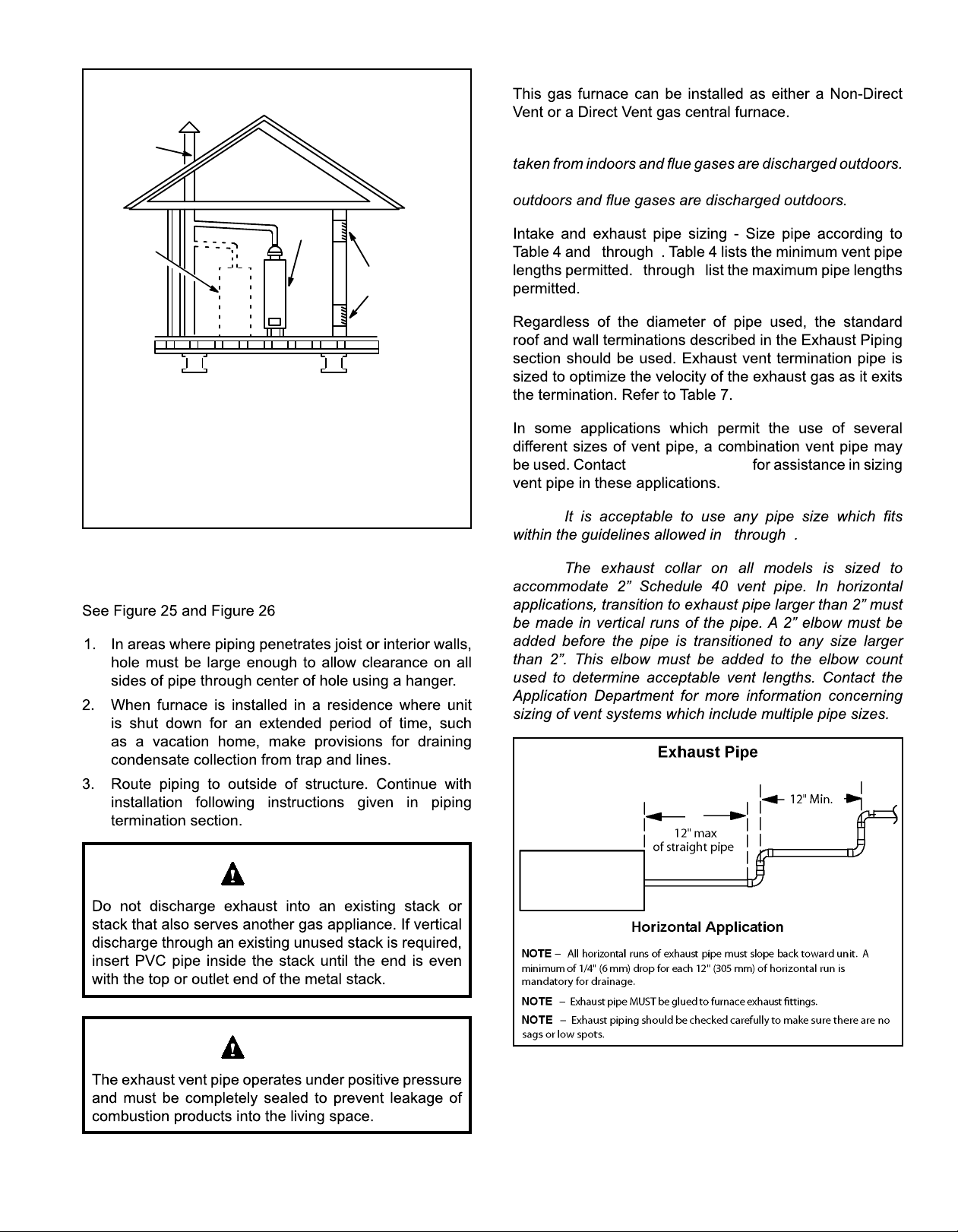
Figure 25.
Figure 26.
507276-05CPage 22 of 57 mrcool.com
Page 24

Intake Piping
Figure 27.
Figure 28.
507276-05C Page 23 of 57mrcool.com
Page 25

Figure 29.
CAUTION
Figure 30.
Ventilation Louvers
Roof Terminated
Exhaust Pipe
*Intake Debris
Screen
(Provided)
Furnace
Inlet Air
(Minimum 12 in.
(305mm) above
Attic Floor)
* See Maximum Vent Lengths table
NOTE:
Figure 31.
(Inlet Air from Ventilated Attic and Outlet Air to
Outside)
507276-05Cmrcool.com
Page 26

Roof Terminated
Exhaust Pipe
Ventilation
Louvers
(Crawl Space)
Furnace
NOTE:
Inlet Air
Minimum
12 in. (305mm)
above Crawl
Space Floor
NOTE:
Coupling or
3 in. to 2 in.
Transition
(Field Provided)
*Intake Debris Screen Provided
* See Maximum Vent Lengths table
NOTE:
Figure 32.
(Inlet Air from Ventilated Crawl Space and Outlet Air
to Outside)
General Guidelines for Vent Terminations
IMPORTANT
IMPORTANT
For Canadian Installations Only:
507276-05C Page 25 of 57mrcool.com
Page 27

Maximum Allowable Exhaust Vent Pipe Length (in ft.) without Insulation in Unconditioned Space For Winter Design
Winter Design Temperatures
1
2
1
ºF (ºC)
Vent Pipe
Diameter
Unit Input Size
045 070 090 110 135
PVC
2
PP PVC2PP PVC2PP PVC2PP PVC2PP
18 16 31 28 50 30 30
13 56
9 9 18 18 35 35 52 52
9 8 18 16 32 29 30 30
5 13
8 8 19 19 26 26 30 30
5 3 12 10 22 19 30 27
7 15 22
10 10 16 16 18 18
Conditioned
Space
Table 6.
Conditioned
Space
Pipe Insulation
Unconditioned
Space
Exhaust
Pipe
Intake
Pipe
Figure 33. Insulating Exhaust Pipe in an Unconditioned Space
507276-05CPage 26 of 57 mrcool.com
Page 28

VENT TERMINATION CLEARANCES
FOR NON-DIRECT VENT INSTALLATIONS IN THE US AND CANADA
INSIDE CORNER
DETAIL
G
D
A
E
B
L
C
Fixed
F
Closed
Operable
B
Operable
B
B
VENT TERMINAL
AIR SUPPLY INLET
US Installations
A =
Clearance above grade, veranda,
porch, deck or balcony
B =
Clearance to window or
door that may be opened
C =
Clearance to permanently
closed window
Vertical clearance to ventilated soffit
D =
located above the termin
al within a
12 inches (305mm) or 12 in. (305mm)
above average snow accumulation.
4 feet (1.2 m) below or to side of opening;
1 foot (30cm) above opening
* 12”
* Equal to or greater than soffit depth.
horizontal distance of 2 feet (610 mm)
from the center line of the terminal
E =
F =
G =
Clearance to unventilated soffit
Clearance to outside corner
Clearance to inside corner
H =
tended above meter / regulator assembly
I =
Clearance to service regulator
vent outlet
J =
Clearance to non-mechanical air
* Equal to or greater than soffit depth.
* No minimum
3 feet (.9m) within a height 15 feet (4.5m)
*
above the meter / regulator assembly
* 3 feet (.9m)
4 feet (1.2 m) below or to side of opening;
1 foot (30 cm) above opening
pliance
K =
ply inlet
L =
Clearance above paved sidewalk or
paved driveway located on public property
M =
Clearance under veranda, porch, deck or balcony
1
In accordance with the current ANSI Z223.1/NFPA 54 Natural Fuel Gas Code
2
In accordance with the current CSA B149.1, Natural Gas and Propane Installation Code
† A vent shall not terminate directly above a sidewalk or paved driveway that is
located between two single family dwellings and serves both dwellings.
‡ Permitted only if veranda, porch, deck or balcony is fully open
on a minimum of two sides beneath the floor. HVAC Distributing recommends
avoiding this location if possible.
3 feet (.9m) above if within 10 feet
(3m) horizontally
7 feet (2.1m)†
*12 inches (305mm)‡
H
B
Fixed
Closed
A
J
I
M
AREA WHERE TERMINAL
IS NOT PERMITTED
1
Canadian Installations
2
12 inches (305mm) or 12 in. (305mm)
above average snow accumulation.
6 inches (152mm) for appliances <10,000
Btuh (3kw), 12 inches (305mm) for
appliances > 10,000 Btuh (3kw) and
<100,000 Btuh (30kw), 36 inches (.9m)
for appliances > 100,000 Btuh (30kw)
* 12”
* Equal to or greater than soffit depth.
* Equal to or greater than soffit depth.
to outside corner * No minimum to outside corner
**
3 feet (.9m) within a height 15 feet (4.5m)
above the meter / regulator assembly
3 feet (.9m)
6 inches (152mm) for appliances <10,000
Btuh (3kw), 12 inches (305mm) for
appliances > 10,000 Btuh (3kw) and
<100,000 Btuh (30kw), 36 inches (.9m)
for appliances > 100,000 Btuh (30kw)
6 feet (1.8m)
7 feet (2.1m)†
12 inches (305mm)‡
*For clearances not specified in ANSI Z223.1/NFPA 54 or CSA
B149.1, clearance will be in accordance with local installation
codes and the requirements of the
lation instructions.”
K
Figure 34.
507276-05C Page 27 of 57mrcool.com
Page 29

VENT TERMINATION CLEARANCES
FOR DIRECT VENT INSTALLATIONS IN THE USA AND CANADA
INSIDE CORNER
DETAIL
G
D
A
E
B
L
C
Fixed
F
Closed
Operable
B
Operable
B
A
B
VENT TERMINAL
AIR SUPPLY INLET
US Installations
A =
B =
Clearance above grade, veranda,
porch, deck or balcony
Clearance to window or
door that may be opened
12 inches (305mm) or 12 in. (305mm)
above average snow accumulation.
6 inches (152mm) for appliances <10,000
Btuh (3kw), 9 inches (228mm) for ap-
pliances > 10,000 Btuh (3kw) and <50,000
Btuh (15kw), 12 inches (305mm) for ap-
pliances > 50,000 Btuh (15kw)
C =
D =
Clearance to permanently
closed window
Vertical clearance to ventilated soffit
located abo
ve the terminal within a
horizontal distance of 2 feet (610mm)
* 12”
* Equal to or greater than soffit depth * Equal to or greater than soffit dept
from the center line of the terminal
E =
F =
G =
H =
Clearance to unventilated soffit
Clearance to outside corner
Clearance to inside corner
Clearance to each side of center line ex-
tended above meter / regulator assembly
I =
Clearance to service regulator
vent outlet
J =
Clearance to non-mechanical air
supply inlet to building or the com-
bustion air inlet to any other ap-
pliance
* Equal to or greater than soffit depth * Equal to or greater than soffit depth
* No minimum to outside corner
*
3 feet (.9m) within a height 15 feet (4.5m)
above the meter / regulator assembly
*
3 feet (.9m)
6 inches (152mm) for appliances <10,000
Btuh (3kw), 9 inches (228mm) for ap-
pliances > 10,000 Btuh (3kw) and <50,000
Btuh (15kw), 12 inches (305mm) for ap-
pliances > 50,000 Btuh (15kw)
K =
Clearance to mechanical air sup-
ply inlet
L =
Clearance above paved sidewalk or
paved driveway located on public property
M =
Clearance under veranda, porch, deck or balcony
1
In accordance with the current ANSI Z223.1/NFPA 54 Natural Fuel Gas Code
2
In accordance with the current CSA B149.1, Natural Gas and Propane Installation Code
† A vent shall not terminate directly above a sidewalk or paved driveway that is located
between two single family dwellings and serves both dwellings.
‡ Permitted only if veranda, porch, deck or balcony is fully open on a minimum of
two sides beneath the floor. HVAC Distributing recommends avoiding this location
if possible.
3 feet (.9m) above if within 10 feet
(3m) horizontally
* 7 feet (2.1m)
*12 inches (305mm)‡
H
Fixed
Closed
J
B
I
M
K
AREA WHERE TERMINAL
IS NOT PERMITTED
1
Canadian Installations
2
12 inches (305mm) or 12 in. (305mm)
above average snow accumulation.
6 inches (152mm) for appliances <10,000
Btuh (3kw), 12 inches (305mm) for
appliances > 10,000 Btuh (3kw) and
<100,000 Btuh (30kw), 36 inches (.9m)
for appliances > 100,000 Btuh (30kw)
* 12”
h
* No minimum to outside corner
*
3 feet (.9m) within a height 15 feet (4.5m)
above the meter / regulator assembly
3 feet (.9m)
6 inches (152mm) for appliances <10,000
Btuh (3kw), 12 i
nches (305mm) for
appliances > 10,000 Btuh (3kw) and
<100,000 Btuh (30kw), 36 inches (.9m)
for appliances > 100,000 Btuh (30kw)
6 feet (1.8m)
7 feet (2.1m)†
12 inches (305mm)‡
*For clearances not specified in ANSI Z223.1/NFPA 54 or CSA
B149.1, clearance will be in accordance with local installation
codes and the requirements of the gas supplier and these
installation instructions.”
Figure 35. Vent Termination Clearances for Direct Installations
507276-05CPage 28 of 57 mrcool.com
Page 30

Details of Intake and Exhaust Piping
Terminations for Direct Vent Installations
NOTE: In Direct Vent installations, combustion air is taken
NOTE:
Inches (MM)
8” (203MM) MIN
12” (305MM) ABOVE
AVERAGE SNOW
ACCUMULATION
3” (76MM) OR
2” (51MM) PVC
PROVIDE SUPPORT
FOR INTAKE AND
EXHAUST LINES
3” (76MM) MIN.
SIZE PER EXHAUST PIPE
TERMINATION SIZE
REDUCTION TABLE
UNCONDITIONED
ATTIC SPACE
1/2” (13MM) FOAM
INSULATION IN
UNCONDITIONED
SPACE
Figure 36. Direct Vent Roof Termination Kit
(15F75 or 44J41)
Capacity Exhaust Pipe Size
Termination
Pipe Size
90
110
135
Table 7. Exhaust Pipe Termination Size Reduction
NOTE:
Figure 37.
Figure 38.
507276-05C Page 29 of 57mrcool.com
Page 31

NOTE − FIELD−PROVIDED
REQUIRED TO ADAPT
LARGER VENT PIPE SIZE
* WALL
SUPPORT
C1
REDUCER MAY BE
TO TERMINATION
C1
A
E
D
B
Intake
Elbow
STRAIGHT
APPPLICATION
D
B
A
EXTENDED
APPLICATION
FIELD FABRICATED WALL TERMINATION
A− Minimum clearance
above grade or average
snow accumulation
B− Maximum horizontal
separation between
intake and exhaust
C1 -Minimum from end of
exhaust to inlet of intake
C2 -Minimum from end of
exhaust to inlet of intake
D− Maximum exhaust
pipe length
E− Maximum wall support
distance from top of each
pipe (intake/exhaust)
D
B
* Use wall support every 24” (610 mm). Use two
wall supports if extension is greater than
24” (610 mm) but less than 48” (1219 mm).
NOTE − One wall support must be within 6” (152 mm)
from top of each pipe (intake and exhaust) to prevent
movement in any direction.
C2
D
B
C2
A
E
A
2” (51mm)
Vent Pipe
12” (305 mm)
12” (305 mm)
3” (76mm)
Vent Pipe
12” (305 mm)
6” (152 mm)6” (152 mm)
8” (203 mm)8” (203 mm)
6” (152 mm)6” (152 mm)
20” (508 mm)
6” (152 mm)6” (152 mm)
ALTERNATE TERMINATIONS (TEE & FORTY−FIVE DEGREE ELBOWS ONLY)
2” (51MM)
Vent Pipe
12” (305 mm) Min. 12” (305 mm) Min.
6” (152 mm) Min.
24” (610 mm) Max.
9” (227 mm) Min.
12” (305 mm) Min.
16” (405 mm) Max.
6” (152 mm) Max.
Front View of
Intake and Exhaust
Intake
Exhaust
Intake
Elbow
B
C
A
E
B
Exhaust
D
3
D
1
12”
C
A− Clearance above
grade or average snow
accumulation
B− Horizontal
separation between
intake and exhaust
C− Minimum from
end of exhaust to
inlet of intake
D− Exhaust pipe length
E− Wall support distance
from top of each pipe
(intake/exhaust)
2
A
D
B
1
C
2
A
D
E
B
C
1
12”
2
A
1
The exhaust termination tee should be connected to the 2” or 3” PVC flue pipe as shown in the illustration.
Do not use an accelerator in applications that include an exhaust termination tee.
The accelerator is not required.
2
As required. Flue gas may be acidic and may adversely affect some building materials. If a side wall vent
termination is used and flue gases will impinge on the building materials, a corrosion-resistant shield
(24 inches square) should be used to protect the wall surface. If optional tee is used, the protective shield
is recommended. The shield should be constructed using wood, sheet metal or other suitable material.
All seams, joints, cracks, etc. in affected area, should be sealed using an appropriate sealant.
3
Exhaust pipe 45° elbow can be rotated to the side away from the combustion air inlet to direct exhaust
away from adjacent property. The exhaust must never be directed toward the combustion air inlet.
3” (76MM)
Vent Pipe
6” (152 mm) Min.
24” (610 mm) Max.
9” (227 mm) Min.
12” (305 mm) Min.
20” (508 mm) Max.
6” (152 mm) Max.
Figure 39.
507276-05CPage 30 of 57 mrcool.com
Page 32

Figure 40.
Figure 42.
Figure 43.
8” - 12”
(203MM - 305MM)
3”-8”
(76MM-203MM)
STRAIGHT-CUT OR
ANGLE-CUT IN DIRECTION
OF ROOF SLOPE
Figure 41.
507276-05C Page 31 of 57mrcool.com
Minimum 12” (305MM)
above chimney top
plate or average snow
accumulation
INTAKE PIPE
INSULATION (optional)
SHEET
METAL TOP
PLATE
INSULATE
TO FORM
SEAL
SHOULDER OF FITTINGS
PROVIDE SUPPORT
OF PIPE ON TOP PLATE
3” - 8”
(76MM-
203MM)
ALTERNATE
INTAKE PIPE
EXTERIOR
PORTION OF
CHIMNEY
* SIZE TERMINATION PIPE
PER EXHAUST PIPE TERMINATION
SIZE REDUCTION TABLE
Figure 44. Direct Vent Application Using Existing
Chimney
Page 33

Direct Vent Applications
12” (305MM)
ABOVE AVE.
SNOW
ACCUMULATION
3” (76MM) OR
2” (51MM) PVC
PROVIDE SUPPORT
FOR EXHAUST LINES
SIZE PER EXHAUST PIPE
TERMINATION SIZE
REDUCTION TABLE
UNCONDITIONED
ATTIC SPACE
SIZE TERMINATION
PER EXHAUST PIPE
TERMINATION SIZE
REDUCTION TABLE
* Use wall support every 24” (610 mm). Use two supports of extension is greater than 24”
(610 mm) but less than 48” (1219 mm).
Figure 47.
Termination Extended
STRAIGHT-CUT OR
ANGLE-CUT IN DIRECTION
OF ROOF SLOPE
Figure 45.
SIZE TERMINATION
PER EXHAUST PIPE
TERMINATION SIZE
REDUCTION TABLE
Figure 46.
15F75 or 44J41)
Termination
Minimum 12” (305MM)
above chimney top
plate or average snow
Figure 48.
accumulation
SHEET
METAL TOP
PLATE
INSULATE
TO FORM
SEAL
* SIZE TERMINATION PIPE
PER EXHAUST PIPE TERMINATION
SIZE REDUCTION TABLE
Chimney
SHOULDER OF FITTINGS
PROVIDE SUPPORT
OF PIPE ON TOP PLATE
EXTERIOR
PORTION OF
CHIMNEY
507276-05CPage 32 of 57 mrcool.com
Page 34

Exhaust through Crawl Space Vent Option
Exhaust from
Furnace
To Termination
Figure 49.
2” or 3”
Sanitary Tee
1/2” PVC
Drain Stub
Drain Trap
Assembly
Rubber Boot (51W18)
Drain Plug (15Z70)
Clamp
(51W18 Only)
From
Furnace
Downflow Furnace
Exhaust
To Vent
Termination
Drain Trap
(assembled)
Exhaust from
Furnace
To Termination
* Kit 51W18 is shown.
Figure 50. Crawl Space Vent Pipe Drain Trap
Assembled Incorrectly
24” max.
KIT 51W18 (USA)
KIT 15Z70 (Canada)
NOTE:
NOTE:
Figure 51.
507276-05C Page 33 of 57mrcool.com
* Kit 51W18 is shown.
Basement Floor
To Termination
1/2” PVC to
Code-Approved
Drain
Page 35

Condensate Piping
NOTE:
NOTE:
NOTE:
CAUTION
Figure 52.
CAUTION
507276-05Cmrcool.com
Page 36

Figure 53. Condensate Trap Locations
Figure 54.
Switch
WARNING
507276-05C Page 35 of 57mrcool.com
Page 37

Figure 55. Condensate Trap Locations
Figure 56. Unit with Cooling Coil Using Separate
Drain
Figure 58. Evaporator Coil Using a Common Drain
Figure 57. Evaporator Coil Using a Common Drain
507276-05CPage 36 of 57 mrcool.com
Page 38

Figure 59.
507276-05C Page 37 of 57mrcool.com
Page 39

Gas Piping
IMPORTANT
CAUTION
Leak Check
WARNING
NOTE:
IMPORTANT
Figure 60.
IMPORTANT
WARNING
FIRE OR EXPLOSION HAZARD
507276-05CPage 38 of 57 mrcool.com
Page 40

Figure 61. Gas Piping
Figure 62. Gas Piping
Horizontal Applications
507276-05C Page 39 of 57mrcool.com
Page 41

Nominal
Iron Pipe
inches
(mm)
1 680 375 320 285 260 220 205 195
2 3950 2750 2200 1900 1680 1520 1300 1220 1150
3 11000 7700 6250 5300 3900 3700 3250
Internal
Diameter
(mm)
10
(3.048)20(6.096)30(9.144)40(12.192)50(15.240)60(18.288)70(21.336)80(24.384)90(27.432)
175 120 97 82 73 66 61 57 53 50
360 250 200 170 151 138 125 118 110 103
950 770 660 580 530
2100 1180 990 900 810 750 690 650 620
6300 3520 3000 2650 2250 2050 1950 1850
100
(30.480)
NOTE
23000 15800 12800 10900 9700 9700 8100 7500 7200 6700
Table 8.
507276-05Cmrcool.com
Page 42

Electrical
ELECTROSTATIC DISCHARGE (ESD)
Precautions and Procedures
CAUTION
NOTE:
Figure 63.
Figure 64.
507276-05C mrcool.com
NOTE:
Accessory Terminals
Page 43

Indoor Blower Speeds
Figure 65.
•
•
•
•
Figure 66. Typical Field Wiring Diagram
507276-05Cmrcool.com
Page 44

E045B3
E070B3
E090C4
E110C5
E135D5
Figure 67. Typical Wiring Diagram
507276-05C mrcool.com
Page 45

LINE
CIRC
EAC
COOL
FAN
NEUTRALS
FS
Figure 68. Integrated Control
(Automatic Hot Surface Ignition System)
Terminal Designations
FOR YOUR SAFETY READ BEFORE OPERATING
WARNING
WARNING
CAUTION
BEFORE LIGHTING
Placing the Furnace into Operation
507276-05Cmrcool.com
Page 46

Priming Condensate Trap
WARNING
Figure 69.
NOTE:
Gas Valve Operation
See Figure 69
STOP!
STOP!
Turning Off Gas to Unit
Failure To Operate
507276-05C mrcool.com
Heating Sequence Of Operation
Page 47

Gas Pressure Adjustment
Gas Flow (Approximate)
Gas Meter Clocking Chart
Seconds for One Revolution
Capacity
-70 55 110 136 272
-90
-110 33 66 82
-135 27 68 136
Natural LP
1 cu ft
Dial
80 160 200
2 cu ft
Dial
82 102
1 cu ft
Dial
Supply Pressure Measurement
Manifold Pressure Measurement
2 cu ft
Dial
NOTE:
Table 9. Gas Meter Clocking Chart
NOTE:
Capacity Gas
Propane
NOTE
Proper Combustion
Capacity CO2% for Nat CO2% for L.P.
Manifold Pressure in. w.g.
Table 10.
Supply Line Pressure
in. w.g.
Table 11.
507276-05Cmrcool.com
Page 48

High Altitude Information
NOTE:
Capacity
070
090
110
135
Capacity
High Altitude
Propane Natural
73W80* 51W01
Pressure Switch Requirements at Varying Altitudes
070 10U93
Natural Burner
Propane Burner
090 11U70 10U93
110 10U93
135 11U70 10U93
Table 12.
507276-05C mrcool.com
Page 49

WARNING
CARBON MONOXIDE POISONING HAZARD
Do not operate
a summer exhaust fan
507276-05Cmrcool.com
Page 50

Other Unit Adjustments
Primary Limit
Flame Rollout Switches (Two)
Pressure Switch
Temperature Rise
Fan Control
Figure 70.
Electrical
Blower Speeds
NOTE:
Constant Torque Motor
Thermostat Heat Anticipation
507276-05C mrcool.com
Electronic Ignition
Page 51

Blower Performance
MGM95SE045B3XA Performance (Less Filter)
External
Static
Pressure
in. w.c.
MGM95SE070B3XA Performance (Less Filter)
External
Static
Pressure
in. w.c.
High Medium Low
cfm Watts cfm Watts cfm Watts cfm Watts cfm Watts
1255 1150 185 895 105 95
1305 1225 250 1105 200 855 110 810 95
1290 360 1190 260 1080 205 825 120 780 105
1275 370 1150 270 215 785 125 720 110
1220 385 1120 280 1015 220 735 135 690 120
1215 390 1090 290 980 230 705 635 125
1190 395 1060 300 950 650 150 600 135
1015 300 900 250 620 155 555
1000 310 870 260 580 160 520
High Medium Low
cfm Watts cfm Watts cfm Watts cfm Watts cfm Watts
1380 315 1305 250 1190 200 965 105 920 100
1360 325 1270 255 1180 205 915 115 865 100
1310 335 1250 265 1130 215 880 120 815 110
1275 1205 275 1100 225 835 125 775 115
1250 355 1175 280 1065 230 795 135 730 125
1215 370 295 670 130
1200 380 1100 310 995 705 150
380 1070 310 960 255 670 160 585
1035 320 925 265 610 165 550 155
MGM95SE090C4XA Performance (Less Filter)
External
Static
Pressure
in. w.c.
High Medium Low
cfm Watts cfm Watts cfm Watts cfm Watts cfm Watts
370 1505 250 1370 195 1285 160 1135 125
1695 390 265 1325 205 170 1090 135
1660 280 1290 220 1195 185
1615 1390 295 235 200 995 160
1590 1350 305 1200 1110 210 165
1560 1310 320 1155 260 1055 225 895 175
1525 1255 335 1105 270 1005 230 855 190
1220 1065 285 960 805 200
1170 355 1010 295 920 255 760 210
NOTE
507276-05CPage 50 of 57 mrcool.com
Page 52

MGM95SE110C5XA Performance (Less Filter)
External
Static
Pressure
in. w.c.
Bottom Return Air, Side Return Air with Optional Return Air Base, Return Air from
Both Sides or Return Air from Bottom and One Side.
High Medium Low High Medium Low
cfm Watts cfm Watts cfm Watts cfm Watts cfm Watts cfm Watts cfm Watts cfm Watts cfm Watts cfm Watts
2220 1765 335 1635 280 200 2185 655 1915 1620 275 195
2170 660 1920 1715 350 1595 290 1380 205 2160 660 1880 1705 1570 285 1380 205
2130 680 1865 1670 370 1560 305 220 2115 680 1835 1670 365 1535 305 1325 220
2095 700 1835 390 1525 325 1285 230 2060 705 1795 1630 380 1505 320 1285 230
2065 720 1785 510 1600 335 1250 2050 720 1760 510 1570 330 1235
2030 1755 525 1560 355 1215 260 2000 1720 530 1535 1195 260
1995 760 1705 550 1525 1380 370 1150 270 1950 760 1685 550 1505 1380 365 275
1955 770 1660 560 1350 375 1100 290 1935 775 1650 555 1325 375 1100 285
1930 790 1635 575 1300 395 1050 305 1890 790 1610 575 1285 390 1050 295
MGM95SE135D5XA Performance (Less Filter)
External
Static
Pressure
in. w.c.
Bottom Return Air, Side Return Air with Optional Return Air Base, Return Air from
Both Sides or Return Air from Bottom and One Side.
High Medium Low High Medium Low
cfm Watts cfm Watts cfm Watts cfm Watts cfm Watts cfm Watts cfm Watts cfm Watts cfm Watts cfm Watts
2235 735 2070 1830 390 1620 280 2395 925 2235 710 2020 550 1800 380 1610 275
2365 960 2210 2020 565 1770 1585 295 2360 935 2175 735 2005 555 1760 395 1550 295
2330 975 2180 770 1950 580 1535 315 2350 955 2160 760 1955 565 1725 1510 300
2295 1000 2120 785 1925 595 1690 325 2290 990 2195 775 1890 590 1700 325
2275 1015 2075 805 1885 615 2255 995 2060 795 1850 615 1635 1390
2225 1025 2035 815 630 1605 1395 360 2230 1010 815 625 1590 1375 360
2185 1010 2020 835 1815 1565 1330 365 2170 1025 2000 820 1795 1580 1335 370
850 1736 665 1520 500 1310 385 1935 1725 660 1520 500 1295 385
1890 860 1715 680 510 1285 1880 855 1705 680 510 1260
NOTE
507276-05C Page 51 of 57mrcool.com
Page 53

Allowable Heating Speeds
Model Red Yellow Blue Brown Black
070
090
110
135
Table 13.
Allowable Circulation Speeds
Model Red Yellow Blue Brown Black
Table 14.
Service
Exhaust and Air Intake Pipes
WARNING
ELECTRICAL SHOCK, FIRE, OR EXPLOSION
HAZARD.
Blower
WARNING
NOTE:
Electrical
Winterizing and Condensate Trap Care
Cleaning Heat Exchanger
Filters
507276-05CPage 52 of 57 mrcool.com
Page 54

507276-05C Page 53 of 57mrcool.com
Page 55

Cleaning the Burner Assembly
507276-05Cmrcool.com
Page 56

Planned Service
Fresh air grilles and louvers
Burners
Vent pipe
Unit appearance
Blower access door
Return air duct
Operating performance
Combustion gases
Instruct the homeowners to pay attention to their
furnace.
Red LED Flash Code
1
1
NOTE
Table 15.
507276-05C Page 55 of 57mrcool.com
Page 57

Red LED Flash Code
1
1
2
NOTE
2
Repair Parts List
Cabinet Parts
•
•
• Top Cap
Control Panel Parts
• Transformer
•
•
Blower Parts
•
•
•
•
•
Table 16.
Heating Parts
•
•
•
•
•
•
•
•
•
•
•
507276-05CPage 56 of 57 mrcool.com
Page 58

Requirements for Commonwealth of Massachusetts
requirements:
INSTALLATION OF CARBON MONOXIDE
DETECTORS
INSPECTION
EXEMPTIONS: The following equipment is exempt
from 24 CMR 5.08(2)(a) 1 through 4:
VENTING SYSTEM PROVIDED.
APPROVED CARBON MONOXIDE DETECTORS.
SIGNAGE
GAS VENT DIRECTLY
BELOW. KEEP CLEAR OF ALL OBSTRUCTIONS.
VENTING SYSTEM NOT PROVIDED.
A copy of all installation instructions for all Product
equipment, all venting instructions, all parts lists
instructions shall remain with the appliance or
equipment at the completion of the installation.
507276-05C Page 57 of 57mrcool.com
Page 59

Signature Series
MGM*95SE*XA Gas Furnace
ELECTRICIAN and /or HVAC TECHNICIAN:
LICENSE #:
INSTAL LATI ON DAT E:
INSTALLATION LOCATION:
SERIAL NUMBER:
The design and specifications of this product and/or manual are subject to change without prior notice.
Consult with the sales agency or manufacturer for details.
 Loading...