

Page 1
MGM80S*A & MGD80S*A
PRODUCT SPECIFICATIONS
INSTALLATION FEATURES
• Left or right utility connections
• Removable floor base for bottom return air
upflow / horizontal units)
• Zero step horizontal conversion
CONFIGURATIONS
• Upflow / Horizontal
• Downflow
HEAT EXCHANGER DESIGN
Aluminized steel tapered crimped non-welded
•
clam shell heat exchanger design
BURNERS
• Aluminized steel inshot burners for
smooth ignition
GAS FURNACE
SINGLE STAGE
Note: Not Sold In Canada
California Only
If installed in South Coast Air Quality Management District (SCAQMD) only: This
furnace does not meet the SCAQMD Rule 1111 NOx emission limit (14 ng/J), and thus is
subject to a mitigation fee of up to $450. This furnace is not eligible for the Clean Air
Furnace Rebate Program: www.CleanAirFurnaceRebate.com.
If installed in San Joaquin Valley Air Pollution Control District (SJVAPCD) only: This
furnace does not meet the SJVAPCD Rule 4905 NOx emission limit (14 ng/J), and
thus is subject to a mitigation fee of up to $450.
CABINET DESIGN
• Compact 33” height
• Standardized widths for easy coil fit
AIR DELIVERY SYSTEM
Multi-speed high efficiency (constant torque)
•
blower motor
•
Easily removable slide out blower design
•
Enhanced cooling SEER ratings when applied
with properly matched cooling equipment
CONTROLS
•
Single stage gas valve
Durable silicon nitride ignitor
•
Self diagnostics saving last 10 fault codes regardlesss of
•
power interruption
•
Control features electronic air cleaner and humidifier
terminals
VENTING
• Rotatable draft inducer for venting flexibility
WARRANTY
10-Year limited parts warranty / lifetime heat exchanger warranty
available. See limited warranty document for details.
-
mrcool.com
Page 1
Page 2
80% GAS FURNACE MGM80S*A & MGD80S*A
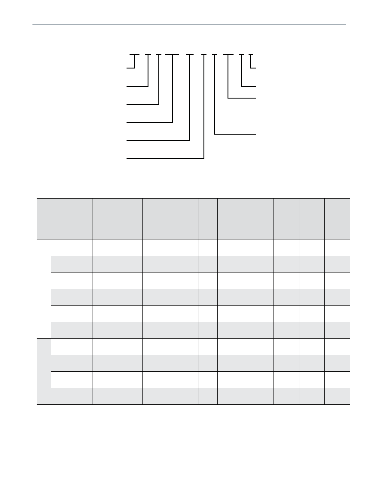
MODEL NUMBER GUIDE
M G M 80 S C 45 A 3 A
COMPANY
M = MRCOOL
GAS
G = GAS FURNACE
AIRFLOW
M = MULTI-POSITION
D = DOWNFLOW
AFUE
ANNUAL FUEL UTILIZATION EFFICIENCY
STAGE
S = SINGLE STAGE / MULTI SPEED
MOTOR
C = PSC
E = ECM
PHYSICAL AND ELECTRICAL DATA
Model
Input
(Btuh)
Output
(Btuh)
AFUE
(ICS)
Nom.
Cooling
Capacity
Gas
Inlet
(in.)
Volts/
Hz/
Phase
REV CODE
A = 2ND GENERATION
CFM
2 = 800, 3 = 1200, 4 = 1600, 5 = 2000
CABINET SIZE
A = 14.5
B = 17.5
C = 21
D = 24.5
BTU
Max.
Time
Delay
Breaker
or Fuse
Nominal
F.L.A.
Trans.
(V.A.)
Approx.
Shipping
Weight
(lbs.)
MGM80SE045A3A 44,000 35,200 80.0% 1-1/2 — 3 1/2 120-60-1 15 6.8 40 111
MGM80SE070B3A 66,000 52,800 80.0% 1-1/2 — 3 1/2 120-60-1 15 6.8 40 127
MGM80SE090B4A 88,000 70,400 80.0% 2-1/2 — 4 1/2 120-60-1 15 8.4 40 142
MGM80SE090C5A 88,000 70,400 80.0% 3 — 5 1/2 120-60-1 15 10.9 40 152
MGM80SE110C5A 110,000 88,000 80.0% 4 — 5 1/2 120-60-1 15 10.9 40 160
UPFLOW / HORIZONTAL
MGM80SE135D5A 132,000 105,600 80.0% 4 — 5 1/2 120-60-1 15 10.9 40 178
MGD80SE045A3A 44,000 35,200 80.0% 2 — 3 1/2 120-60-1 15 6.8 40 113
MGD80SE070B3A 66,000 52,800 80.0% 2 — 3 1/2 120-60-1 15 6.8 40 128
MGD80SE090B4A 88,000 70,400 80.0% 3 — 4 1/2 120-60-1 15 8.4 40 140
DOWNFLOW
MGD80SE110C5A 110,000 88,000 80.0% 4 — 5 1/2 120-60-1 15 10.9 40 160
Note: For vent le ngth and clearances to combusti bles , plea se refe rence installation instructions .
mrcool.com
Page 2
Page 3

80% GAS FURNACE
MGM80S*A & MGD80S*A
DIMENSIONS (IN.)
Model A B C D
Front View
MGM80SE045A3A
MGM80SE070B3A
MGM80SE090C5A
MGM80SE090B4A 21 19-3/8 19-1/2 8
MGM80SE110C5A 21 19-3/8 19-1/2 8
MGM80SE135D5A 24-1/2 23-3/8 23 9-3/4
UPFLOW / HORIZONTAL
MGD80SE045A3A 14-1/2 13-3/8 13 4-3/4
MGD80SE070B3A 17-1/2 16-3/8 16 6-1/4
MGD80SE090B4A 17-1/2 16-3/8 16 6-1/4
DOWNFLOW
MGD80SE110C5A 21 19-7/8 19-1/2 8
14-1/2 13-3/8 13 4-3/4
17-1/2 16-3/8 16 6-1/4
17-1/2 16-3/8 16 6-1/4
Upflow / Horizontal
Downflow
Right
Side
View
AIR
FLOW
17-1/2
Right
Side
View
9
6-5/8
Upflow / Horizontal
19-1/2
Downflow
25
AIR
FLOW
C
19-1/4
All specifications and illustrations subject to
change without notice and without incurring
obligations.
Bottom
View
Bottom
View
mrcool.com
Page 3
Page 4

80% GAS FURNACE
BLOWER PERFORMANCE DATA
Motor
Size
(hp)
1/2 10 x 8 15 - 45
1/2 10 x 10 40 - 70
3/4 10 x 10 35 - 65
1 11-1/2 x 10 30 - 60
1 11-1/2 x 10 35 - 65
1 11 x 11 30 - 60
1/2 10 x 8 15 - 45
1/2 10 x 10 30 - 60
3/4 10 x 10 30 - 60
1 11-1/2 x 10 30 - 60
MGM80SE045A3A
MGM80SE070B3A
MGM80SE090B4A
MGM80SE090C5A
UPFLOW / HORIZONTAL
MGM80SE110C5A
MGM80SE135D5A
MGD80SE045A3A
MGD80SE070B3A
MGD80SE090B4A
DOWNFLOW
MGD80SE110C5A
Model
Blower
Size
Temp
Rise
(°F)
MGM80S*A & MGD80S*A
CFM @ External Static Pressure - " w.c.
Blower
Speed
0.20 0.30 0.40 0.50 0.60 0.70 0.80
High 1320 1290 1265 1230 1190 1165 1130
Med/High 1080 1055 1010 990 945 915 880
Med 900 875 825 790 750 705 670
Med/Low 805 750 710 660 630 570 535
Low 700 640 595 535 500 435 380
High 1355 1330 1290 1245 1225 1190 1160
Med/High 1225 1190 1155 1115 1045 1000 925
Med 1110 1060 1015 980 920 855 790
Med/Low 1080 1035 970 930 865 790 735
Low 885 825 770 695 625 540 445
High 1730 1690 1645 1615 1590 1545 N/A
Med/High 1505 1460 1435 1395 1350 1300 1270
Med 1380 1345 1310 1265 1210 1175 1140
Med/Low 1310 1275 1240 1180 1150 1095 1040
Low 1110 1065 1010 955 915 860 820
High 2150 2125 2090 2060 2020 1980 1935
Med/High 1865 1835 1800 1760 1725 1680 1635
Med 1655 1635 1585 1545 1515 1465 1420
Med/Low 1490 1450 1405 1370 1320 1265 1225
Low 1340 1285 1235 1200 1145 1105 1055
High 2135 2090 2050 2025 2010 1965 1905
Med/High 1865 1830 1785 1740 1710 1670 1635
Med 1630 1595 1550 1500 1470 1420 1380
Med/Low 1470 1440 1385 1340 1305 1255 1215
Low 1280 1235 1175 1130 1080 1015 975
High 2390 2360 2285 2240 2225 2160 2105
Med/High 2175 2140 2125 2060 2015 1955 1925
Med 1935 1895 1850 1815 1785 1755 1715
Med/Low 1735 1720 1660 1610 1535 1500 1435
Low 1550 1485 1455 1415 1330 1265 1215
High 1375 1335 1320 1275 1245 1215 1175
Med/High 1145 1120 1075 1045 1000 970 925
Med 950 915 870 835 785 745 695
Med/Low 840 790 745 715 655 605 555
Low 725 665 625 565 520 455 400
High 1400 1360 1310 1280 1250 1220 1165
Med/High 1230 1205 1155 1110 1060 1000 935
Med 1125 1085 1050 985 935 865 795
Med/Low 1110 1055 1000 950 865 815 750
Low 900 845 790 705 645 590 480
High 1695 1660 1615 1570 1545 N/A N/A
Med/High 1470 1425 1395 1360 1295 1265 1215
Med 1340 1290 1250 1210 1165 1120 1080
Med/Low 1280 1225 1185 1145 1085 1040 1000
Low 1105 1040 1005 945 865 810 755
High 2325 2280 2235 2165 2125 2090 2035
Med/High 2010 1940 1895 1845 1800 1755 1700
Med 1760 1705 1635 1595 1545 1510 1460
Med/Low 1570 1500 1440 1380 1320 1285 1255
Low 1375 1320 1265 1200 1170 1100 1030
mrcool.com
Page 4
 Loading...