

Page 1

The Signature Series is NOT designed for amateur installation. Installation SHOULD be performed by an authorized technician.
Please read this manual carefully before installation and keep it for future reference.
Owner & Installation
Manual
Signature Series
MPC*1M414A & MPH*1M414A
Residential Packaged Units
The Signature Series is NOT designed for amateur installation. Installation SHOULD be performed by an authorized technician.
Please read this manual carefully before installation and keep it for future reference.
Page 2
THIS MANUAL MUST BE LEFT WITH THE
HOMEOWNER FOR FUTURE REFERENCE
WARNING
Installation and servicing of air conditioning equipment
can be hazardous due to internal refrigerant pressure
and live electrical components. Only trained and
INSTALLATION AND MAINTENANCE
INSTRUCTIONS
MPC*1M414A
& MPH*1M414A
Air Conditioners and Heat Pumps
C
Table of Contents
Installation ...................................................................2
Electrical Wiring...........................................................3
Duct System ................................................................4
Filters...........................................................................5
Condensate Drain........................................................5
Sequence of Operation................................................
Maintenance................................................................
Wiring Diagrams........................................................11
this equipment. Installation and service performed by
WARNING
other appliance. Such actions could result in property
WARNING
If this unit is to be installed in a mobile or manufactured
guidelines. All other installation guidelines must also
the unit.
Manufactured By
MRCOOL LLC
*F507296-C*
C
CAUTION
The installation of this appliance must conform to the requirements of the National Fire Protection Association; the
jurisdiction should be consulted before installation is made. Such applicable regulations or requirements take precedence
over the general instructions in this manual.
Save these instructions for future reference
507296-02C Page 1 of 12mrcool.com
Page 3
Location
WARNING
or maintenance can cause injury or property damage.
Refer to this manual. For assistance or additional
agency.
Installation
These instructions explain the recommended method of
installation of the packaged heat pump and air conditioner
system.
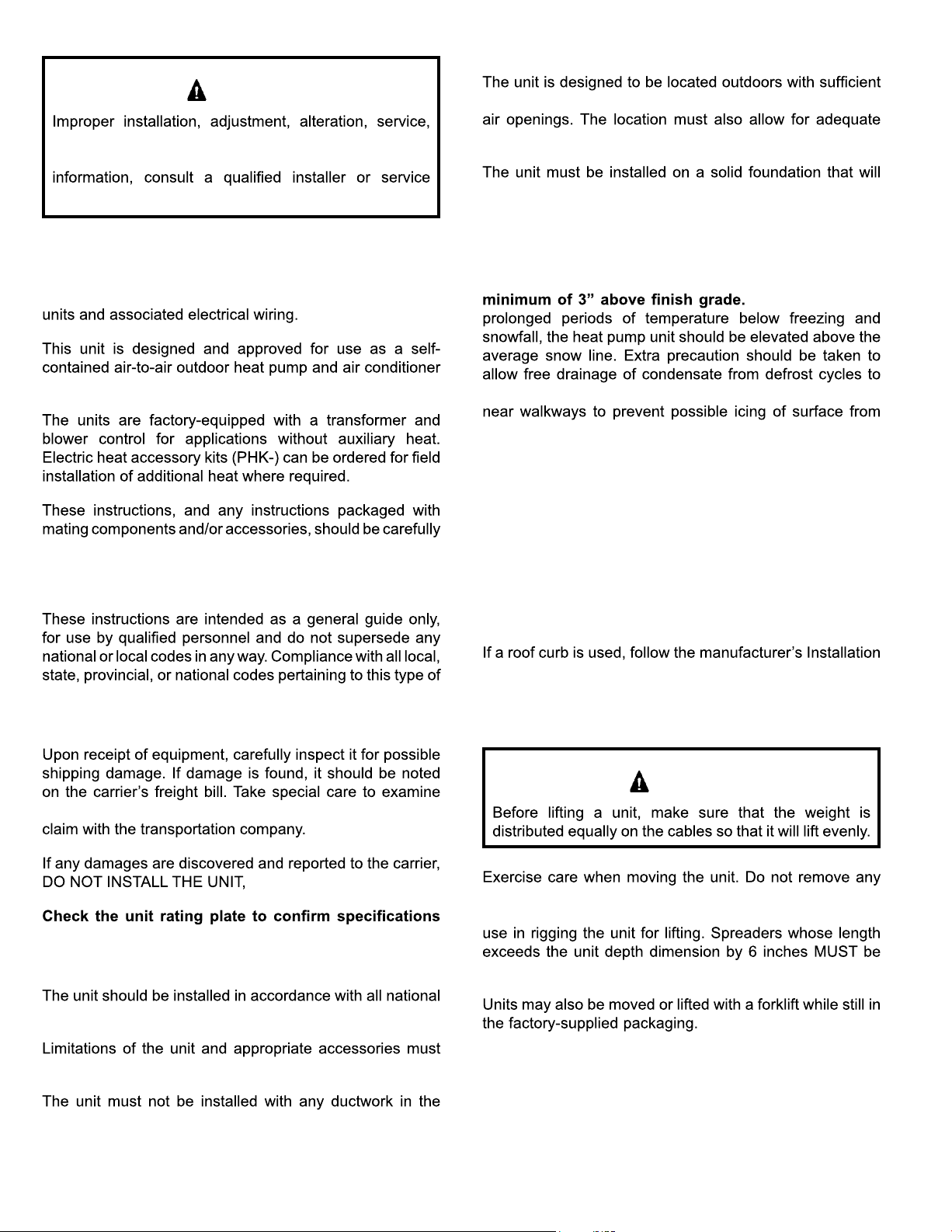
clearance for free entrance to the air inlet and discharge
service access.
not settle or shift. Adequate structural support must be
provided. Install the unit in level position. Isolate the base
from the building structure to avoid possible transmission
of sound or vibration into the conditioned space.
The heat pump unit foundation should be raised to a
In areas that have
prevent ice accumulation. The unit should not be located
defrost condensate.
Avoid placing the unit near quiet areas, such as
sleeping quarters or study rooms. Normal operating
sound levels may be objectionable if the unit is placed near
certain rooms.
read prior to beginning installation. Note particularly any
CAUTIONS or WARNINGS in these instructions and all
labels on the units.
equipment should be determined prior to installation.
Inspection of Shipment
the unit inside the carton if the carton is damaged. File a
as claim may be denied.
are as ordered.
Limitations
For improved start-up performance, the indoor coil
should be washed with suitable detergent to remove
any residue from manufacturing processes.
Roof Curb Installation
Instructions and be sure that all required clearances are
observed.
Rigging and Handling
CAUTION
packaging until the unit is near the place of installation.
An optional lifting lug kit may be purchased separately for
used across the top of the unit.
and local safety codes.
of the forklift must be a minimum of 42”.
also be observed.
outdoor air stream. The outdoor fan is not designed to
operate against any additional static pressure.
Page 2 of 12 507296-02Cmrcool.com
The lengths of the forks
Page 4
REDUCE
TO
6.00
REDUCE
TO
W1
C
L
R
O
Y1
FAN
O-OUT
LO-PS
DF
HI-PS
COMMON
Y1 OUT
2
2
24 V
Y
W2
RED
YEL
BLU
WHT
GRN
ORN
W1 & W2 CAN BE USED TO STAGE
ELECTRIC HEAT ACCESSORY ON
15 & 20KW MODELS
5, 7.5 & 10KW HEATER ACCESSORIES
FUNCTION OFF W1 ONLY.
WHT
DEFROST
CONTROL
P-6
P-5
G
W1
C R O
THERMOSTAT
537663-01
NOTE:
IF ANY OF THE ORIGINAL
WIRE IS REPLACED THE
SAME SIZE AND TYPE WIRE
MUST BE USED.
USE COPPER CONDUCTOR
ONLY, MIN 75 C WIRE
CONNECTION MUST BE JUMPERED
WHEN PRESSURE SWITCH IS NOT USED.
LINE VOLTAGE FIELD INSTALLED
WARNING-
ELECTRIC SHOCK HAZARD. UNIT
MUST BE GROUNDED IN ACCORDANCE
WITH NATIONAL AND LOCAL CODES.
REV. VALVE
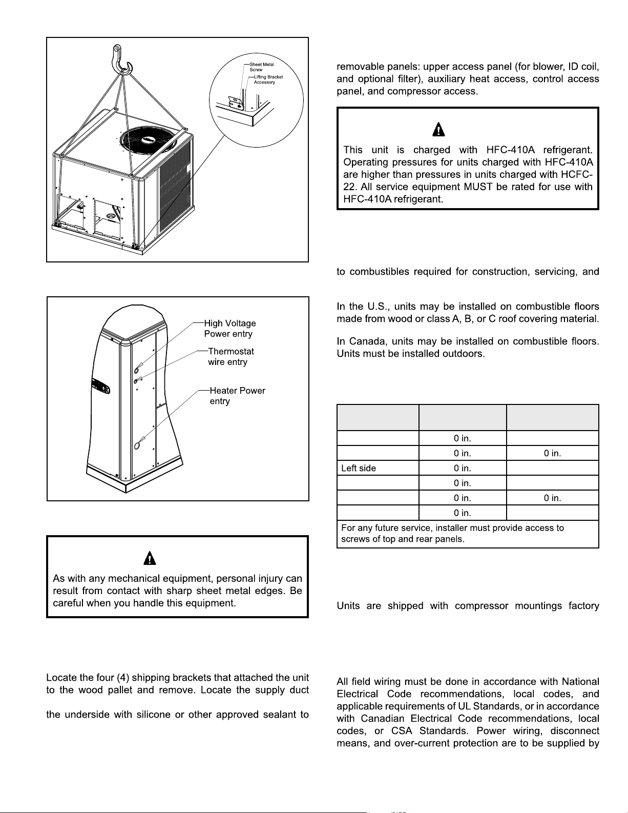
Service Access
Access to all serviceable components is provided by four
WARNING
Figure 1. Rigging Unit
Figure 2. Typical Field Wiring
Clearances
All units require certain clearances for proper operation
and service. Refer to Table 1 for the minimum clearances
proper unit operation.
Do not permit overhanging structures or shrubs to
obstruct condenser air discharge outlet.
Clearance to
Combustibles
Front of unit
Back of unit
Right side
Base of unit
Top of unit 48 in.
Clearance for
Service Access
24 in.
24 in.
24 in.
CAUTION
Compressor
adjusted and ready for operation. Do not loosen
compressor mounting bolts.
Unpacking
Carefully remove outer packaging material and discard.
corner and seal the shipping openings in the base from
prevent air leakage during unit operation.
the installer. Refer to the unit rating plate for maximum
507296-02C Page 3 of 12mrcool.com
Table 1. Minimum Clearances
Electrical Wiring
Page 5
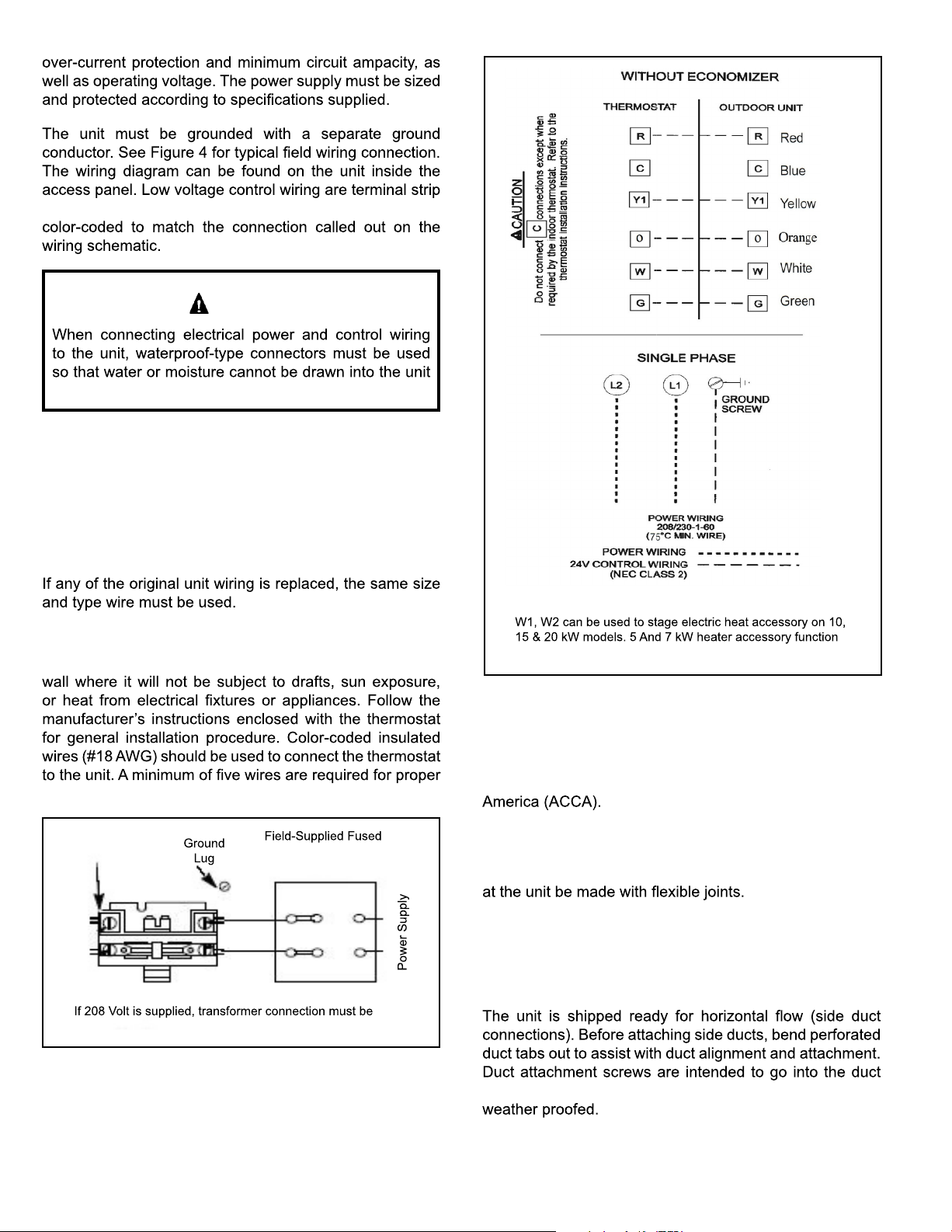
or pigtail leads located on the main control box and are
CAUTION
during normal operation.
Units are factory wired for a 230-volt power supply.
If power supply is 208 volts, it will be necessary to
change a wire connection on the unit transformer from
240V terminal to 208V terminal as shown on the wiring
diagram.
Use only copper conductors.
*
“O” connection used only on heat pump models
*
Thermostat
The room thermostat should be located on an inside
installation.
Contactor
changed
Figure 3. 208/230 Line Voltage Wiring
or Circuit Breaker
Disconnect
Single Phase
off W1 only.
Figure 4. Typical Wiring Connections
Duct System
Duct system should be designed and sized according to the
methods in Manual Q of the Air Conditioning Contractors of
A closed return duct system shall be used. This shall not
preclude use of economizers or outdoor fresh air intake. It
is recommended that supply and return duct connections
The supply and return air duct systems should be designed
for the CFM and static requirements of the job. They
should not be sized to match the dimensions of the
duct connections on the unit.
panel. Duct to unit connections must be sealed and
Page 4 of 12 507296-02Cmrcool.com
Page 6

1.
the unit base insulation to access bottom metal covers
underneath the insulation.
2.
3.
bottom duct connections or roof curb seals.
4.
5.
NOTE: Install drain lines and trap so they do not block
service access to the unit.
See Figure 5 for proper drain arrangement. The drain line
must pitch to an open drain or pump to prevent clogging
material to prevent air leakage into the return air system.
CAUTION
Filters
NOTE:
is limited.
Unit Model Filter 1 Filter 2
Table 2. Unit Air Filter Sizes - inches
Minimum Pitch:
Open
Mounting
Frame
Trap must be deep enough to offset maximum static difference
Figure 5. Typical Condensate Drain Connection
Condensate Drain
Crankcase Heater (if used)
to prevent excessive migration of liquid refrigerant into the
for condensate line connection. Plumbing must conform
to the unit to keep this feature active.
threads.
Do not
the system disconnect switch.
Heater Kit Accessory (if used)
The condensate drain line must be properly trapped,
routed to a suitable drain and primed prior to unit
commissioning.
507296-02C Page 5 of 12mrcool.com
auxiliary heat. A heater kit accessory may also be used. To
1.
do not open
access.
Page 7

2.
and discard.
3. Remove the heater blockoff by removing the four
4. Insert the heater into the control panel and fasten in
the same mounting holes.
5.
connections on the heater kit.
Sequence of Operation
Cooling
Heating - Heat Pump Stage
and outdoor fan. The reversing valve is not energized in
the heating mode. The thermostat again automatically
stops unit operation.
Heating - Auxiliary Electric Heat
continues to operate until all heating elements have turned
off.
Defrost System
compressor and outdoor fan. The thermostat automatically
thermostat and the defrost control.
Defrost Thermostat
The defrost thermostat is located on the outdoor coil.
thermostat contacts close and send a signal to the defrost
control board to start the defrost timing. It also terminates
Figure 6. Heater Kit Accessory Installation
507296-02Cmrcool.com
Page 8

Defrost Control
The defrost control board includes the combined functions
heating operation to defrost mode and back. During the
relay is energized and the defrost begins.
1.
°F in heating
NOTE: 15°F is an approximate temperature,
depending upon model and installation location.
2.
The maximum defrost period is 14 minutes and cannot be
adjusted.
NOTE:
A test option is provided for troubleshooting. The test mode
may be started any time the unit is in the heating mode and
the defrost thermostat is closed or jumpered. If the jumper
the test pins. When the jumper is placed across the TEST
in defrost mode until the defrost thermostat opens or 14
minutes have passed. If the jumper is not removed until
and the defrost time interval must not have expired.
3.
conditions.
DEFROST TIMING
PINS (P1)
TEST
PINS
DIAGNOSTIC
COMPRESSOR
DELAY PINS
REVERSING
VALVE
S87
LOW PRESSURE
SWITCH
DEFROST
THERMOSTAT (S6)
S4
HIGH PRESSURE
SWITCH
LEDS
24V TERMINAL
STRIP
CONNECTIONS
SERVICE LIGHT
CONNECTIONS
Figure 7. Defrost Control Board
Defrost Control Timing Pins
Each timing pin selection provides a different accumulated
compressor run time period during one thermostat run
cycle. This time period must occur before a defrost cycle
again until the jumper is removed and reapplied.
Compressor Delay (Quiet Shift)
NOTE: The 30-second “off” cycle is not functional when
jumpering the TEST pins.
Time Delay
ensures the compressor is off for a minimum amount of
to protect the compressor from short cycling in case the
The delay is bypassed by placing the timer select jumper
Pressure Switch Circuit
defrost control board on heat pump models. Air conditioning
During a single demand cycle, the defrost control will
It is intended that this
product should be set at the 60-minute time interval at
initial installation. If the timing selector jumper is not in
507296-02C mrcool.com
interrupted by any pressure switch wired to the control
board. In addition, the diagnostic LEDs will indicate a
of an open pressure switch (see Table 3).
Page 9

The unit will remain locked out until power to the board
is interrupted, then re-established, or until the jumper
is applied to the TEST pins for 0.5 seconds.
NOTE: The defrost control board ignores input from the
low pressure switch terminals as follows:
If the measured performance value varies from table value
refrigerant to nameplate charge. It is critical that the exact
• During the TEST mode
• During the defrost cycle
•
•
If the TEST pins are jumpered and the 5-minute delay
is being bypassed, the LO PS terminal signal is not
ignored during the 90-second start-up period.
Diagnostic LEDs
Defrost Board Diagnostic LEDs
Green LED
(DS2)
OFF OFF
Red LED
(DS1)
Condition
system performance.
components.
Model
2 Ton 13
2.5 Ton
3 Ton 14
3.5 Ton 14
4 Ton
5 Ton
Suction
Superheat +/- 3°
Subcooling +/- 2°
Table 4. Air Conditioner Unit Cooling System
Performance Values
Model
Suction
Superheat +/- 3°
Liquid Subcooling
Liquid
+/- 2°
ON
Fault & Lockout Codes
OFF
OFF ON
OFF
ON OFF
Table 3. Defrost Control (CMC1) Diagnostic LEDs
System Performance
the suction superheat value to judge performance. When
checking performance of a unit that uses an expansion
system performance.
2 Ton 18
2.5 Ton
3 Ton
3.5 Ton 22
4 Ton 22
5 Ton 5
Table 5. Heat Pump Cooling System Performance
Values
Model Liquid Subcooling +/- 2°
2 Ton
2.5 Ton
3 Ton
3.5 Ton
4 Ton
5 Ton
25
15
28
35
28
Table 6. Heat Pump Heating System Performance
Values
Page 8 of 12 507296-02Cmrcool.com
Page 10

Maintenance
WARNING
Motors
Indoor and outdoor fan and vent motors are permanently
lubricated and require no maintenance.
Before performing maintenance operations on the
shock could cause personal injury or death.
constant torque motor. These motors remain energized and
use Tap 3 for cooling speed and Tap 5 for heating speed.
Outdoor Coil
Periodic inspection and maintenance normally consists of
the outdoor coil surface or other parts in the air circuit.
Cleaning should be as often as necessary to keep the coil
cleaning.
Filters
Replace disposable or clean permanent type as necessary.
Table 7. Cooling Performance - AC Models
80 DB / 67 WB Deg.
Return Air
Cooling
Input
(1000 BTU)
24
42
48 132 143 144 145 151 152 154
24
42 248 325 385 411
48 338 352 455 482
Pressure 65° 70° 75° 80° 82° 85° 90° 95° 100° 105° 110° 115°
135
135 142 143 145 152 154 155
Suction
135 142 143 144 151 152 154 155
132 135 141 143 145 148
131 133 134 135 141 144 152
282 318 388 413 438
Air Temperature Entering Outdoor Coil, Degree F
314 323 358 432 483
damaged.
141 143 148 152 154
351 423
324 415 438
507296-02C mrcool.com
Page 11

Table 9. Cooling Performance - HP Models
80 DB / 67 WB Deg.
Return Air
Cooling
Input
(1000 BTU)
24
42
48 132 135 138 142 143 144
24 255 388 414
42 238 324 348 421 445
48 248 412 438
Pressure 65° 70° 75° 80° 82° 85° 90° 95° 100° 105° 110° 115°
134 138 141 143 145 148 151 152 154 155
133 141 143 145 151 153
Suction
133 134 135 138 142
254 314 322 383
245 312 415 438
138 142 143 144 145 151 152 154
131 134 138 141 144 148 148 148
285 322 343 443
Air Temperature Entering Outdoor Coil, Degree F
151 152 154 155
Table 8. Heating Performance - HP Models
70 Deg. F Return Air Air Temperature Entering Outdoor Coil, Degree F
Cooling
Input
(1000 BTU)
24
42 25 33 42 54
48 32 84 114 122
24 283 312 323
42
48
Pressure 0° 5° 10° 17° 20° 25° 35° 40° 47° 50° 55° 60°
Suction
33 41
31 38 45 55 81 88
35 42 58 82 115
85 111
44 54 58
253 281 312 323
251 258 321 328 335
311 315 322 331 333 341
318 323 332 358 384
281 334 343 355
113 121
507296-02Cmrcool.com
Page 12

S4
S79
S173
J1-11
Wiring Diagrams
LINE VOLTAGE FIELD INSTALLED
CONTACTOR
K1-2
L2
YEL W/ STRIPE
J1-2
PUR
FAN
MOTOR
J2-2
J1: PLUG THROUGH CONTROL PANEL (12 PIN)
J2: PLUG FOR ACCESSORY HEAT (6 PIN)
B4
YEL W/ STRIPE
208/230-1-60
POWER SUPPLY WITH MIN.
C COPPER WIRE
75
BLK
COMPRESSOR
B1
T2
RED
GRY
F
J1-1
ORG
OUTDOOR
BLK W/ STRIPE
R
C
C
S
BLACK
G
N
(IF USED)
HR1
H
HEATER
CRANK
CASE
BLK
CAPACITOR
YEL
J1-3
INDOOR
BLOWER
MOTOR
240V
DUAL
B3
C12
L
208V
BLK
T1
CONTACTOR
24V
L1
K1-1
BLK
TRANSFORMER
TI
BLK
BLK
J2-1
A/C (CONSTANT TORQUE BLOWER)
CONNECTION DIAGRAM
SINGLE PHASE
NOTE: TAP1 FOR FAN ONLY
TAP 2 FOR COOLING
TAP3 FOR HIGH STATIC COOLING
TAP4 AND TAP5 FOR ELECTRIC HEAT- REFER TO HEATING LABEL
IF ANY OF THE ORIGINAL
WIRE IS REPLACED THE
SAME SIZE AND TYPE WIRE
MUST BE USED.
USE COPPER CONDUCTOR
ONLY, MIN 75
C WIRE
WARNING-
ELECTRIC SHOCK HAZARD. UNIT
MUST BE GROUNDED IN ACCORDANCE
WITH NATIONAL AND LOCAL CODES.
537663-01
J2-4
THERMAL PROTECTION
SWITCH (IF USED)
NOTE:
SWITCH (IF USED)
LOW PRESSURE
HIGH PRESSURE
SWITCH
CONTROL CIRCUIT
WIRING TO BE 24 VOLT,
N.E.C. CLASS 2
BLU
RED
BLU
J1-12
YEL
YEL
Y
GRN
CONTACTOR
KI
5
YEL
4
3
YEL
YEL
2
1
GRN
WHT
WHT
BLK
FUNCTION OFF W1 ONLY.
J2-6
J2-5
BLU
WHT
THERMOSTAT
W1
G
C
R
INDOOR BLOWER MOTOR
N
G
L
C
B-3
W1 & W2 CAN BE USED TO STAGE
ELECTRIC HEAT ACCESSORY ON
10, 15 & 20KW MODELS
5 & 7.5KW HEATER ACCESSORIES
S1
Figure 8. Connections Diagram - A/C Constant Torque
507296-02C Page 11 of 12mrcool.com
Page 13

C WIRE
DIAGNOSTIC CODES FOR DEFROST CONTROL LEDS
NOTE:
IF ANY OF THE ORIGINAL
WIRE IS REPLACED THE
SAME SIZE AND TYPE WIRE
MUST BE USED.
USE COPPER CONDUCTOR
ONLY, MIN 75
C
L
G
N
FUNCTION OFF W1 ONLY.
5 & 7.5 KW HEATER ACCESSORIES
W1 & W2 CAN BE USED TO STAGE
ELECTRIC HEAT ACCESSORY ON
10, 15 & 20KW MODELS
J2-5
J2-6
1
2
3
4
BLK
WHT
WHT
GRN
YEL
DEFROST
5
INDOOR BLOWER MOTOR
NOTE: TAP1 FOR FAN ONLY
TAP 2 FOR COOLING
TAP3 FOR HIGH STATIC COOLING
TAP4 AND TAP5 FOR ELECTRIC HEAT- REFER TO HEATING LABEL
CONNECTION DIAGRAM, HEAT PUMP
BLU
(IF USED)
FLOAT SWITCH
RED
CONSTANT TORQUE BLOWER, SINGLE PHASE
YEL
G
THERMOSTAT
WHT
FAN
CONTROL
REV. VALVE
J1-5
GRY
L1
W1
WHT
BLU
W1
O-OUT
J1-6
J1-8
GRY
BLK
LOW PRESSURE
C
C
LO-PS
J1-9
BLK
S79
SWITCH
RED
L
J1-7
BRN
DEFROST
R
R
DF
J1-10
BRN
T'STAT
ORG
O
24 V
COMMON
S6
O
YEL
Y1
Y1 OUT
Y
S1
CONTROL CIRCUIT WIRING TO
BE 24 VOLT, NEC CLASS-2
CMC1
HI-PS
J1-11
J1-12
S173
SWITCH
(IF USED)
YEL
YEL
THERMAL PROTECTION
YEL
CONTACTOR
BLU
WARNING-
ELECTRIC SHOCK HAZARD. UNIT
MUST BE GROUNDED IN ACCORDANCE
WITH NATIONAL AND LOCAL CODES.
S4
SWITCH
HIGH PRESSURE
J2-4
K1
BLU
GRN
537661-01
T1
BLK
TRANSFORMER
BLK
J2: PLUG FOR ACCESSORY HEAT (6 PIN)
J1: PLUG THROUGH CONTROL PANEL (12 PIN)
Note: Because the Pressure Switches are monitored only when "Y1" (Input) is active, the code
for pressure switch open will not be seen when "Y1" is off. Instead, the "Normal Operation" or
"Anti Short Cycle" code will be seen.
Also, when a pressure switch opens and caused a short cycle lockout, the pressure switch-open
code will be seen until it closes, then the short cycle lockout code will flash unless it has already
expired.
J2-1
FAN
Simultaneous Slow Flash
DS1 (GREEN) DS2 (RED)
BLK
CONTACTOR
K1-1
L1
Control
Description
No Power to Control OFF OFF
Anti-Short Cycle Lockout Alternate Slow Flash
Low Pressure Switch Fault OFF Slow Flash
(See instructions or markings on System Diagnostic
Normal Operation / Power to
Module for codes of System Diagnostic Module)
High Pressure Switch Fault Slow Flash OFF
Low Pressure Switch Lockout OFF ON
High Pressure Switch Lockout ON OFF
BLU
24V
240V
208V
BLU
WHT
J2-2
B4
CONDENSER
FAN MOTOR
GRY
K1-2
CONTACTOR
YEL W/STRIPE
YEL W/STRIPE
T2
L2
L
C
NC
BLK
T1
BLK
INDOOR
BLOWER
B3
BLK
CMC1
DEFROST
CONTROL
BLK
MOTOR
PUR
C12
N
G
J1-3
J1-1
J1-2
ORG
F
C
H
DUAL
YEL
B1
COMPRESSOR
HR1
CAPACITOR
RED
BLK
208/230V-1PH,60HZ
S
C
CASE
CRANK
R
HEATER
(IF USED)
LINE VOLTAGE FIELD INSTALLED
Figure 9. Connections Diagram - Heat Pump Constant Torque
Page 12 of 12 507296-02Cmrcool.com
Page 14

Signature Series
MPC*1M414A & MPH*1M414A
Residential Package
ELECTRICIAN a nd/or HVAC TECHNICIAN:
LICENSE #:
INSTALL AT ION DATE:
INSTALLATION LOCATION:
SERIAL NUMBER:
The design and specifications of this product and/or manual are subject to change without prior notice.
Consult with the sales agency or manufacturer for details.
 Loading...