

Page 1

The Signature Series is NOT designed for amateur installation. Installation SHOULD be performed by an authorized technician.
Please read this manual carefully before installation and keep it for future reference.
Owner & Installation
Manual
Signature Series
MGD80*SE*XA Warm Air Gas Furnace
The Signature Series is NOT designed for amateur installation. Installation SHOULD be performed by an authorized technician.
Please read this manual carefully before installation and keep it for future reference.
Page 2
INSTALLATION INSTRUCTIONS
MGD80*SE*XA
Warm Air Gas Furnace
This manual must be left with the homeowner for future reference.
Table of Contents
Unit Dimensions 2
Parts Arrangement 3
MGD80*E Gas Furnace 4
Safety Information 4
11
Duct System 11
19
21
4
6
6
8
25
29
30
33
34
WARNING
Manufactured By
MRCOOL, LLC
Hickory, KY 42051
Save these instructions for future reference
507332-02C Page 1 of 35mrcool.com
CAUTION
*P507332-02C*
(P) 507332-02C
Page 3
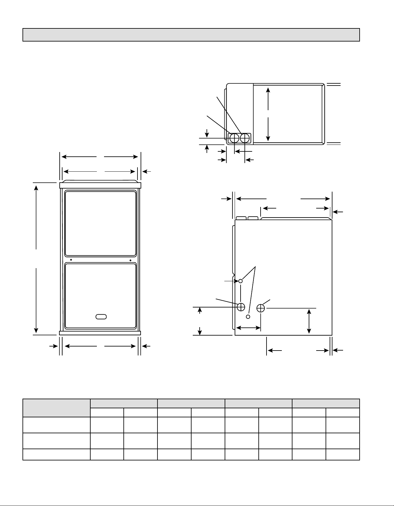
Unit Dimensions
COMBUSTION
AIR INTAKE
Top View
9/16
(14)
33
(838)
A
B
9/16
(14)
EXHAUST AIR
OUTLET
2-1/6 (52)
1 (25)
Front Panel
2 (51)
Either Side
GAS PIPING INLET
(Either Side)
2-1/4 (57)
5
(127)
ELECTRICAL INLET
(Either Side)
RETURN AIR
B
OPENING
27-3/4 (705)
19-17/16 (494)
CONDENSATE
TRAP CONNECTION
(Either Side)
9/16
(14)
9/16
(14)
9-1/8 (232) Right
6-9/16 (157) Left
3/4
(19)
Supply Air
C
3/4
(19)
Front View
Capacity
045-3
070-3
090-4 17-1/2 446 16-3/8 416 16 406 6-1/4 159
110-5 21 533 19-7/8 504 19-1/2 495 8 203
14-1/2 368 13-3/8 340 13 330 4-3/4 121
A B C D
in. mm in. mm in. mm in. mm
6-1/2 (165)
Either Side
Supply Air
19-1/4 (489)
Side View
3/4
(19)
507332-02CPage 2 of 35 mrcool.com
Page 4
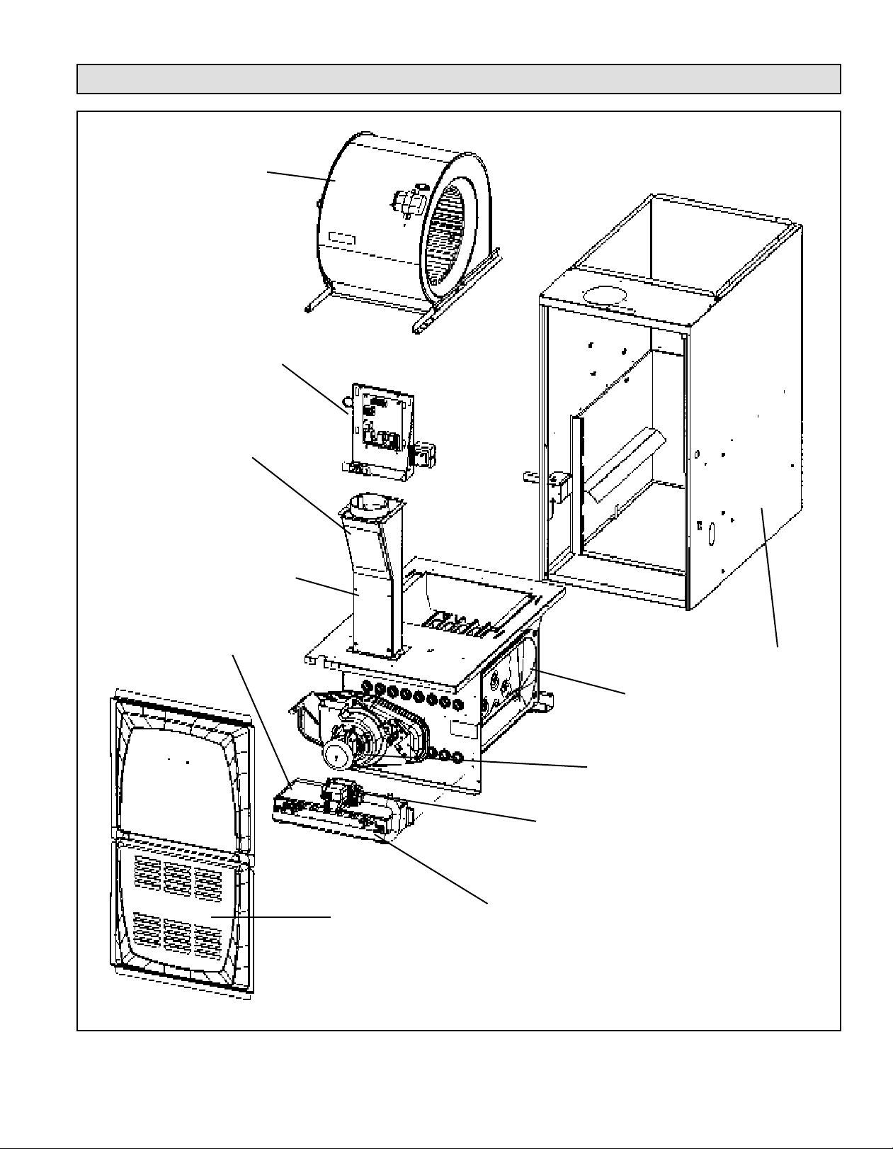
Parts Arrangement
BLOWER
ASSEMBLY
CONTROL
BOX
FLUE
CHASE
INTERNAL
FLUE PIPE
ASSEMBLY
BURNER BOX
ASSEMBLY
ACCESS
PANEL
CABINET
HEAT
EXCHANGER
COMBUSTION AIR
INDUCER
GAS
VALVE
ROLLOUT
LOCATED INSIDE
BURNER BOX
Figure 1.
507332-02C Page 3 of 35mrcool.com
Page 5
MGD80*SE*XA Gas Furnace
MGD80*SE*XA
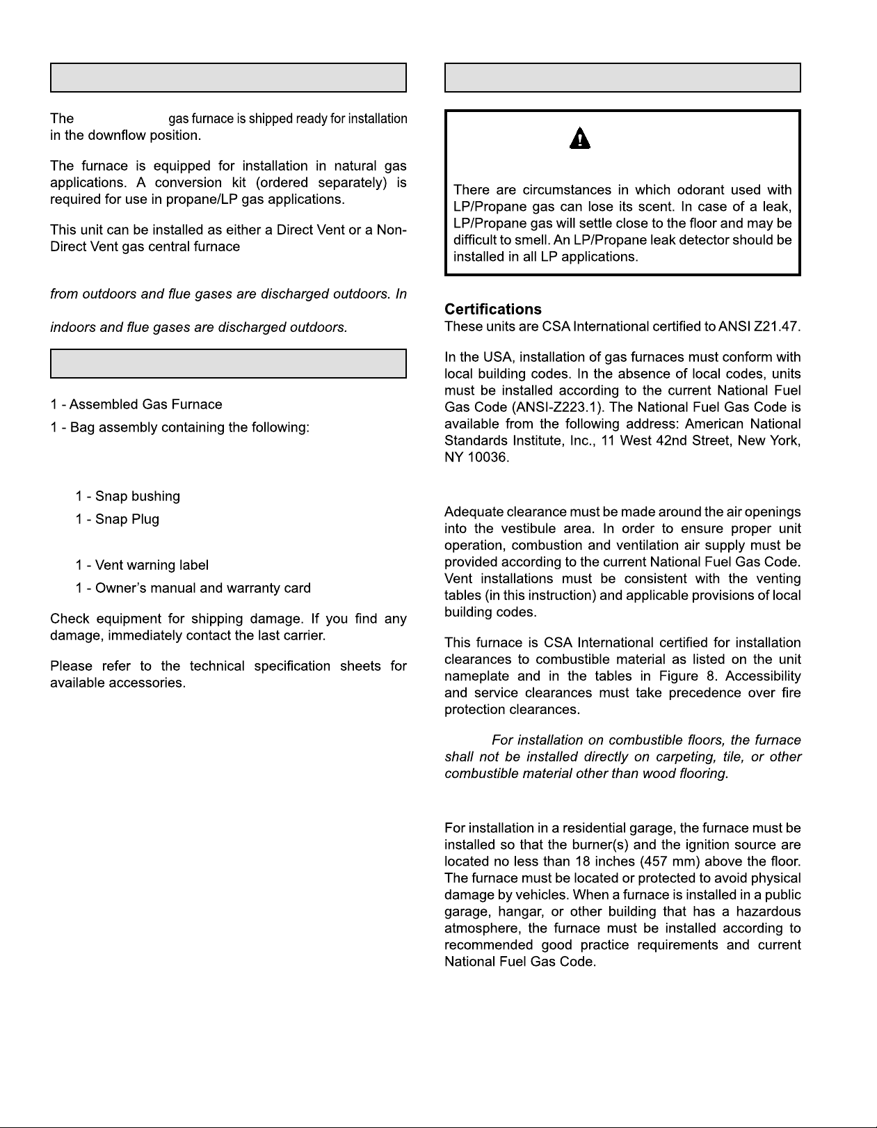
NOTE: In Direct Vent installations, combustion air is taken
Non-Direct Vent installations, combustion air is taken from
Shipping and Packing List
2 - Screws
3 - Wire nuts
Safety Information
WARNING
DANGER OF EXPLOSION!
Clearances
1 - Wire tie
NOTE:
Installed Locations
507332-02CPage 4 of 35 mrcool.com
Page 6

Temperature Rise
NOTE:
Installed in Combination with a Cooling Coil
Use of Furnace as a Construction Heater
DO NOT USE THE UNIT FOR CONSTRUCTION HEAT
UNLESS ALL OF THE FOLLOWING CRITERIA ARE
MET:
Figure 2. Heating Unit Installed Parallel to Air Handler
Unit
Quincy, MA 02269
NOTE:
507332-02C Page 5 of 35mrcool.com
EQUIPMENT MAY EXPERIENCE PREMATURE
COMPONENT FAILURE AS A RESULT OF FAILURE TO
Page 7
DISCLAIMS ALL LIABILITY IN CONNECTION WITH
NOTWITHSTANDING THE FOREGOING, INSTALLER
IS RESPONSIBLE FOR CONFIRMING THAT THE USE
OF CONSTRUCTION HEAT IS CONSISTENT WITH
THE POLICIES AND CODES OF ALL REGULATING
General
•
WARNING
•
•
•
NOTE:
•
•
•
Combustion, Dilution & Ventilation Air
•
•
•
•
•
•
•
•
•
•
•
•
507332-02CPage 6 of 35 mrcool.com
Page 8
3
NOTE:
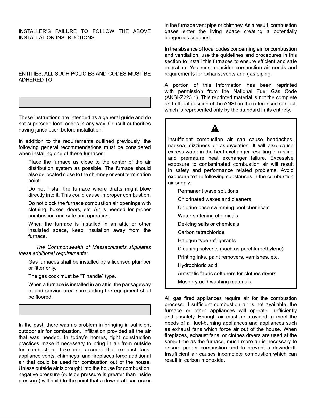
Figure 3.
Inside
Air from Inside
2
Air from Outside
507332-02C Page 7 of 35mrcool.com
Page 9
NOTE:
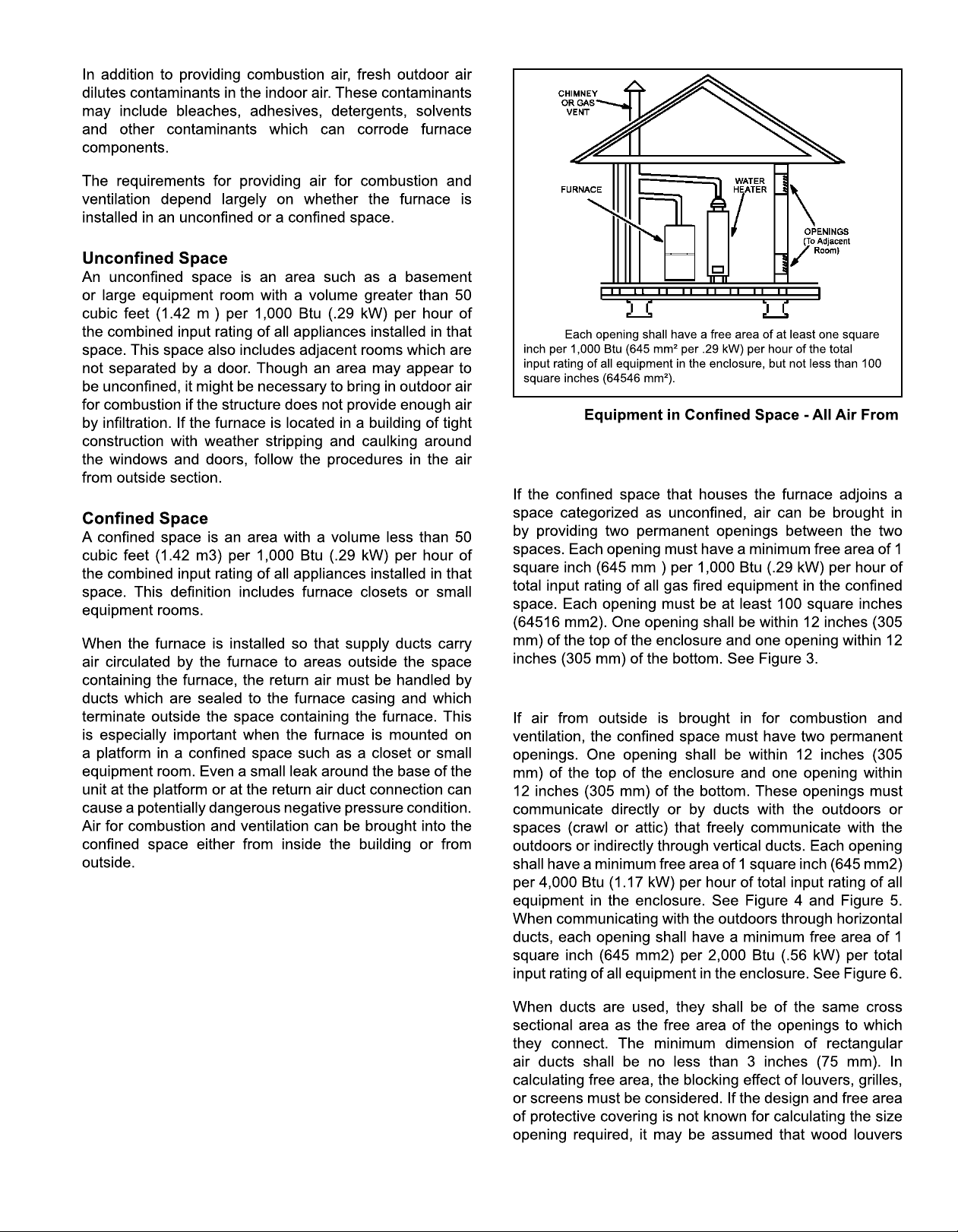
Figure 4.
Outside
(Inlet Air from Crawlspace & Outlet Air to Ventilated
Attic)
NOTE:
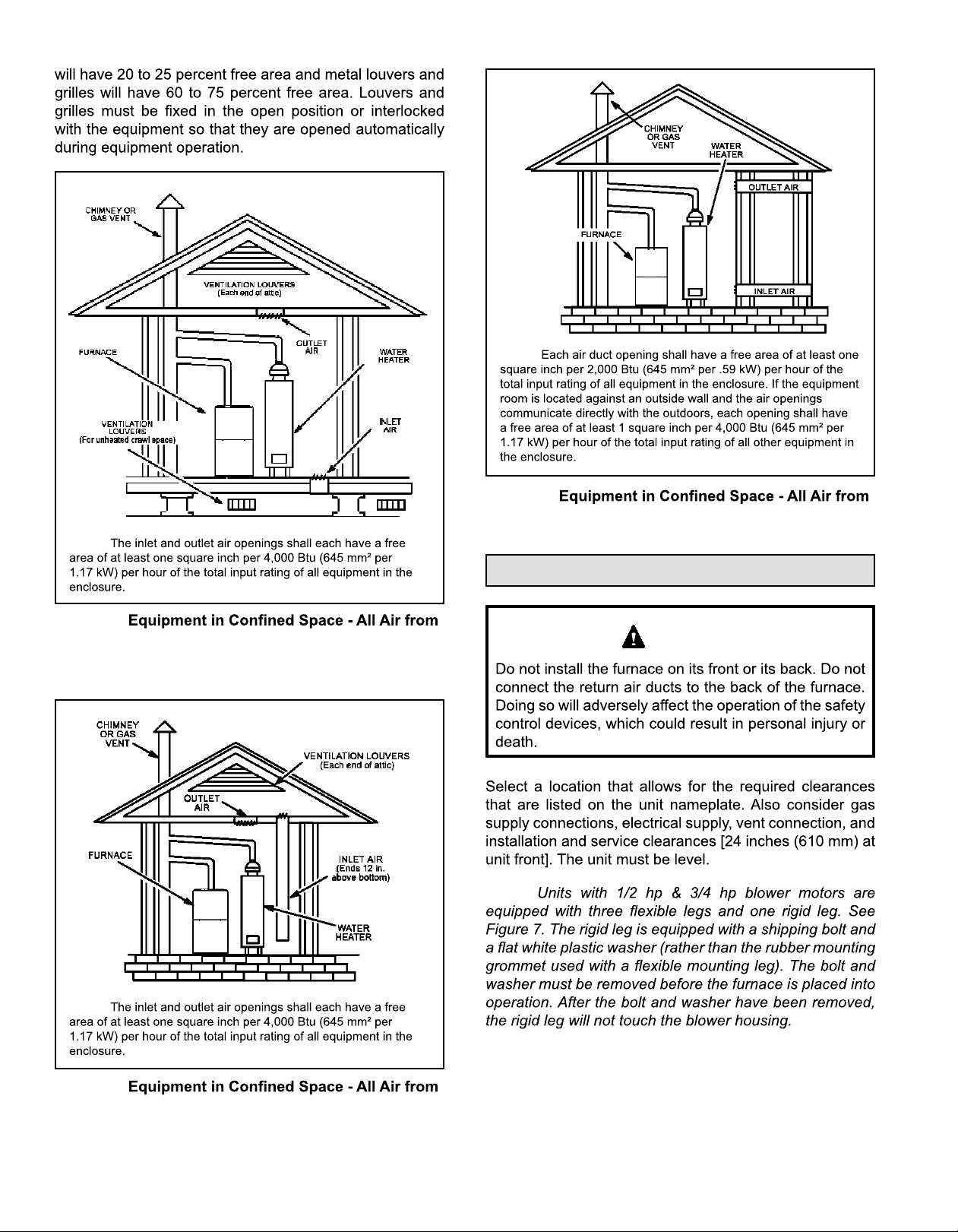
Figure 6.
Outside
Setting Equipment
WARNING
NOTE:
Figure 5.
NOTE:
Outside
(All Air through Ventilated Attic)
507332-02CPage 8 of 35 mrcool.com
Page 10
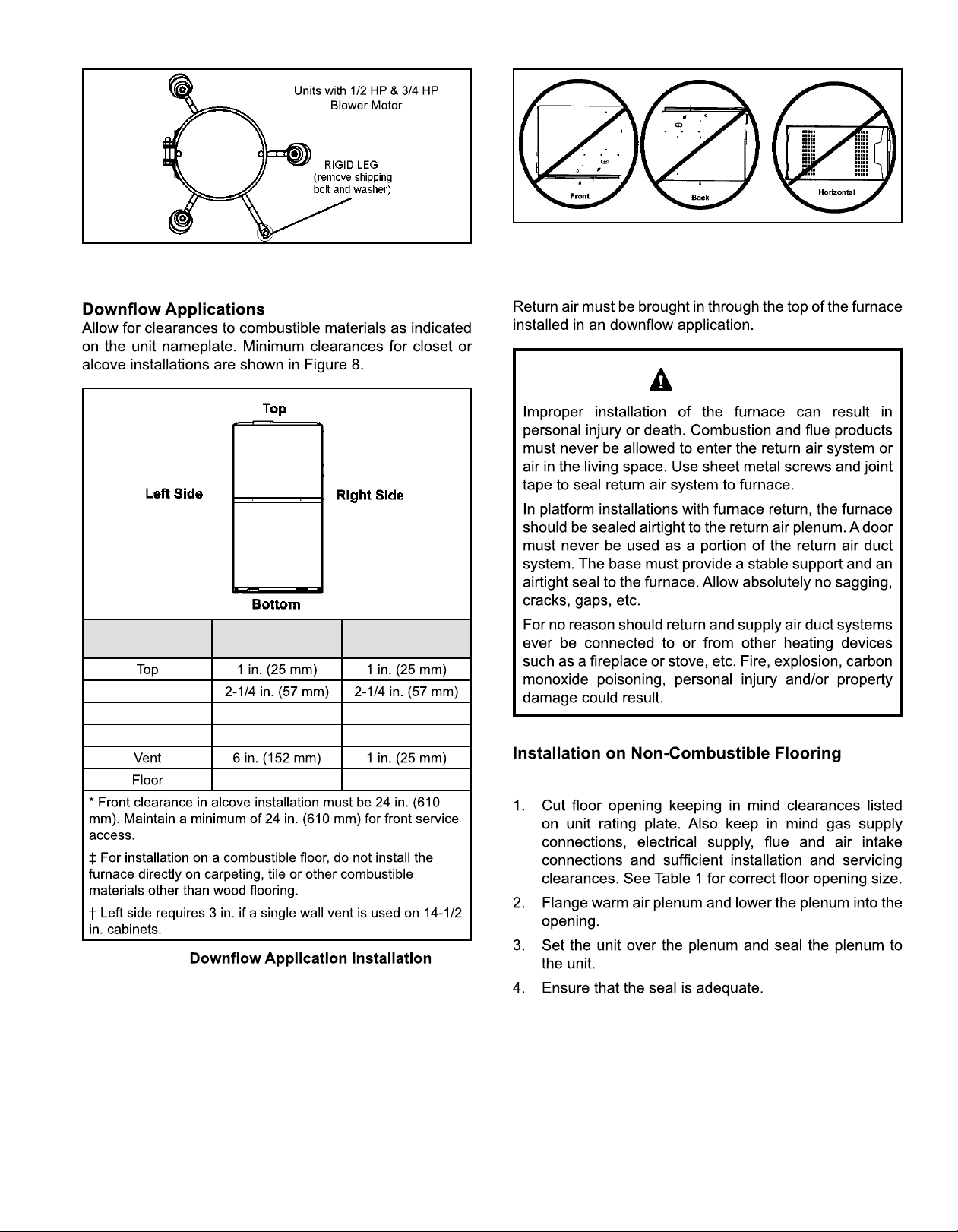
Figure 7.
Figure 9.
Return Air
WARNING
Type of Vent
Connector
*Front
Back 0 0
Sides 0† 0
Type C Type B
0‡ 0‡
Figure 8.
Clearances
1
See Figure 10
507332-02C Page 9 of 35mrcool.com
Page 11
Cabinet Width
NOTE
Table 1.
Front to Rear Side to Side
in. mm in. mm
16-5/8 422
19-3/4 502
20-1/8 511
Figure 11.
Figure 10.
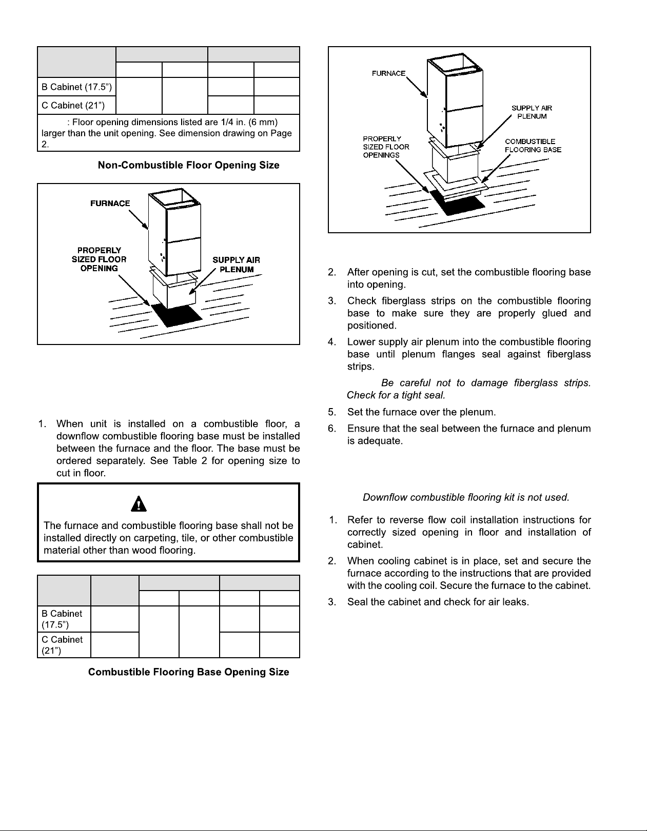
Installation on Combustible Flooring
See Figure 11
CAUTION
Cabinet
Width
Catalog
Number
11M60
11M61 22-3/4 578
Front to Rear Side to Side
in. mm in. mm
22 559
NOTE:
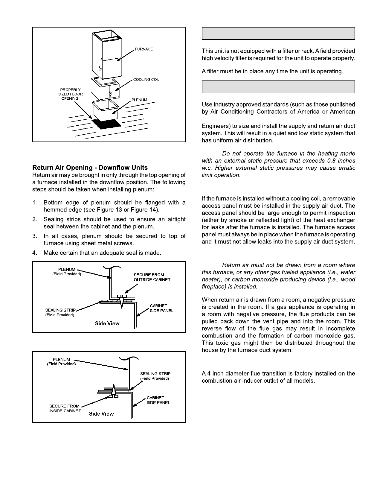
Installation on Cooling Coil Cabinet
See Figure 12
NOTE:
18-3/4 476
Table 2.
507332-02CPage 10 of 35 mrcool.com
Page 12
Filters
Duct System
Society of Heating, Refrigerating and Air Conditioning
Figure 12.
NOTE:
Supply Air Plenum
Return Air Plenum
NOTE:
Figure 13.
Venting
Figure 14.
507332-02C Page 11 of 35mrcool.com
Page 13

IMPORTANT
NOTE:
Figure 15. Vent Connection
Venting Using a Masonry Chimney
IMPORTANT
WARNING
IMPORTANT
507332-02CPage 12 of 35 mrcool.com
Page 14

DO NOT
NOTE 1: Refer to the provided venting tables for installations.
Refer to the capacity requirements shown in the provided
venting tables.
Figure 16.
Masonry Chimney
General Venting Requirements
•
•
NOTE:
Figure 17. Common Venting Using Tile Lined Interior Masonry Chimney and Combined Vent Connector
507332-02C Page 13 of 35mrcool.com
Page 15

Connector Diameter
inches (mm)
3 (76)
4 (102)
5 (127)
6 (152)
7 (178)
Connector Length
feet (m)
Table 3.
507332-02CPage 14 of 35 mrcool.com
Page 16

Capacity of Type B Double Wall Vents with Type B Double Wall Connectors Serving a Single Category I Appliance
Height
(feet)
NOTE
H
10
15
20
30
Lateral
L
(feet)
0 0 78 0 152 0 251 0 375
6
8
2 13 51 18 97 27 157 32 232
4 21 49 30 94 39 153 50 227
6 25 46 36 91 47 149 59 223
0 0 84 0 165 0 276 0 415
2 12 57 16 109 25 178 28 263
5 23 53 32 103 42 171 53 255
8 28 49 39 98 51 164 64 247
0 0 88 0 175 0 295 0 447
2 12 61 17 118 23 194 26 289
5 23 57 32 113 41 187 52 280
10 30 51 41 104 54 176 67 267
0 0 94 0 191 0 327 0 502
2 11 69 15 136 20 226 22 339
5 22 65 30 130 39 219 49 330
10 29 59 40 121 51 206 64 315
15 35 53 48 112 61 195 76 301
0 0 97 0 202 0 349 0 540
2 10 75 14 149 18 250 20 377
5 21 71 29 143 38 242 47 367
10 28 64 38 133 50 229 62 351
15 34 58 46 124 59 217 73 337
20 48 52 55 116 69 206 84 322
0 0 100 0 213 0 374 0 587
2 9 81 13 166 14 283 18 432
5 21 77 28 160 36 275 45 421
10 27 70 37 150 48 262 59 405
15 33 64 44 141 57 249 70 389
20 56 58 53 132 66 237 80 374
30 NR NR 73 113 88 214 104 346
3 inch 4 inch 5 inch 6 inch
Appliance Input Rating in Thousands of Btu per Hour
MIN MAX MIN MAX MIN MAX MIN MAX
Table 4.
507332-02C Page 15 of 35mrcool.com
Page 17

Capacity of Type B Double Wall Vents with Single Wall Metal Connectors Serving a Single Category I Appliance
Height
(feet)
NOTE
H
10
15
20
30
Lateral
L
(feet)
0 38 77 59 151 85 243 126 373
6
8
2 39 51 60 96 85 158 123 231
4 NR NR 74 92 102 152 146 225
6 NR NR 83 89 114 147 163 220
0 37 83 68 164 83 273 123 412
2 39 56 59 108 83 176 121 261
5 NR NR 77 102 107 188 151 252
8 NR NR 90 95 122 161 175 243
0 37 67 57 174 82 293 120 444
2 39 61 59 117 82 193 119 287
5 52 56 76 111 105 185 148 277
10 NR NR 97 100 132 171 188 261
0 36 93 56 190 60 325 116 499
2 38 69 57 136 80 225 115 337
5 51 63 75 128 102 216 144 326
10 NR NR 95 116 128 201 182 308
15 NR NR NR NR 158 186 220 290
0 35 96 54 200 78 346 114 537
2 37 74 56 148 78 248 113 375
5 50 68 73 140 100 239 141 363
10 NR NR 93 129 125 223 177 344
15 NR NR NR NR 155 208 216 325
20 NR NR NR NR 186 192 254 306
0 34 99 53 211 76 372 110 584
2 37 80 55 164 76 281 109 429
5 49 74 72 157 98 271 136 417
10 NR NR 91 144 122 255 171 397
15 NR NR 115 131 151 239 208 377
20 NR NR NR NR 181 223 246 357
30 NR NR NR NR NR NR NR NR
3 inch 4 inch 5 inch 6 inch
Appliance Input Rating in Thousands of Btu per Hour
MIN MAX MIN MAX MIN MAX MIN MAX
Table 5.
507332-02CPage 16 of 35 mrcool.com
Page 18

Vent Connector Capacity
Type B Double Wall Vents with Type B Double Wall Connectors Serving Two or More Category I Appliances
Vent
Height
H
(feet)
6
8
10
15
20
30
Connector
Rise
R
(feet)
1 22 37 35 66 46 106 58 164
2 23 41 37 75 48 121 60 183
3 24 44 38 81 49 132 62 199
1 22 40 35 72 49 114 64 176
2 23 44 36 80 51 128 66 195
3 24 47 37 67 53 139 67 210
1 22 43 34 78 49 123 65 189
2 23 47 36 86 51 136 67 206
3 24 50 37 92 52 146 69 220
1 21 50 33 89 47 142 64 220
2 22 53 35 96 49 153 66 235
3 24 55 36 102 51 163 68 248
1 21 54 33 99 46 157 62 246
2 22 57 34 105 48 167 64 259
3 23 60 35 110 50 176 66 271
1 20 62 31 113 45 181 60 288
2 21 64 33 118 47 190 62 299
3 22 66 34 123 48 198 64 309
3 inch 4 inch 5 inch 6 inch
Appliance Input Rating in Thousands of Btu per Hour
MIN MAX MIN MAX MIN MAX MIN MAX
Table 6.
Common Vent Capacity
Type B Double Wall Vents with Type B Double Wall Connectors Serving Two or More Category I Appliances
Vent Height
H
(feet)
FAN + FAN FAN + NAT FAN + FAN FAN + NAT FAN + FAN FAN + NAT FAN + FAN FAN + NAT
6 92 81 140 116 204 161 309 248
8 101 90 155 129 224 178 339 275
10 110 97 169 141 243 194 367 299
15 125 112 195 164 283 228 427 352
20 136 123 215 183 314 255 475 394
30 152 138 244 210 361 297 547 459
4 inch 5 inch 6 inch 7 inch
Appliance Input Rating in Thousands of Btu per Hour
Table 7.
507332-02C Page 17 of 35mrcool.com
Page 19

Vent Connector Capacity
Type B Double Wall Vents with Single Wall Metal Connectors Serving Two or More Category I Appliances
Vent
Height
H
(feet)
6
8
10
15
20
30
NOTE
Connector
Rise
R
(feet)
1 NR NR NR NR NR NR NR NR
2 NR NR NR NR NR NR 168 182
3 NR NR NR NR 121 131 175 198
1 NR NR NR NR NR NR NR NR
2 NR NR NR NR 125 126 184 193
3 NR NR NR NR 130 138 191 208
1 NR NR NR NR 119 121 182 186
2 NR NR 84 85 124 134 189 203
3 NR NR 89 91 129 144 197 217
1 NR NR 79 87 116 138 177 214
2 NR NR 83 94 121 150 185 230
3 NR NR 87 100 127 160 193 243
1 49 56 78 97 115 152 175 238
2 52 59 82 103 120 163 182 252
3 55 62 87 107 125 172 190 264
1 47 60 77 110 112 175 169 278
2 51 62 81 115 117 185 177 290
3 54 64 85 119 122 193 185 300
3 inch 4 inch 5 inch 6 inch
Appliance Input Rating in Thousands of Btu per Hour
MIN MAX MIN MAX MIN MAX MIN MAX
Table 8.
Common Vent Capacity
Type B Double Wall Vents with Single Wall Metal Connectors Serving Two or More Category I Appliances
Vent Height
H
(feet)
FAN + FAN FAN + NAT FAN + FAN FAN + NAT FAN + FAN FAN + NAT FAN + FAN FAN + NAT
6 N/A 78 N/A 113 200 158 304 244
8 N/A 87 N/A 126 218 173 331 269
10 N/A 94 163 137 237 189 357 292
15 121 108 189 159 275 221 416 343
20 131 118 208 177 305 247 463 383
30 145 132 236 202 350 286 533 446
4 inch 5 inch 6 inch 7 inch
Appliance Input Rating in Thousands of Btu per Hour
Table 9.
507332-02CPage 18 of 35 mrcool.com
Page 20

Removal of the Furnace from Common Vent
WARNING
CARBON MONOXIDE POISONING HAZARD
Gas Piping
CAUTION
Gas Supply
NOTE:
507332-02C Page 19 of 35mrcool.com
IMPORTANT
Page 21

Nominal Iron
inches (mm)
1/2
Internal
Diameter
(mm)
10
(3.048)20 (6.096)30 (9.144)40(12.192)50(15.240)60(18.288)70(21.336)80(24.384)90(27.432)
175 120 97 82 73 66 61 57 53 50
3/4 360 250 200 170 151 138 125 118 110 103
1 680 465 375 320 285 260 240 220 205 195
1-1/4 1400 950 770 660 580 530 490 460 430 400
1-1/2 2100 460 1180 990 900 810 750 690 650 620
2 3950 2750 2200 1900 1680 1520 1400 1300 1220 1150
2-1/2 6300 4350 3520 3000 2650 2400 2250 2050 1950 1850
3 11000 7700 6250 5300 4750 4300 3900 3700 3450 3250
NOTE
100
(30.480)
Left Side Piping
MANUAL
MAIN SHUT-OFF
VALVE
GROUND
JOINT
UNION
(Standard)
DRIP LEG
Table 10.
AUTOMATIC
GAS VALVE
(with manual
shut-off valve)
PROVIDED
AND INSTALLED
NOTE: ONLY
Figure 18.
FIELD
AUTOMATIC
GAS VALVE
(with manual
shut-off valve)
Right Side Piping
(Alternate)
MANUAL
MAIN SHUT-OFF
VALVE
GROUND
JOINT
UNION
DRIP LEG
507332-02CPage 20 of 35 mrcool.com
Page 22

Leak Check
NOTE:
Electrical
ELECTROSTATIC DISCHARGE (ESD)
Precautions and Procedures
CAUTION
CAUTION
IMPORTANT
Figure 19.
Figure 20.
507332-02C Page 21 of 35mrcool.com
Figure 21.
Page 23

NOTE:
NOTE:
•
•
•
•
Thermostat
Accessory Terminals
* Note:
Figure 22. Condensing Unit Thermostat Designations
Indoor Blower Speeds
507332-02CPage 22 of 35 mrcool.com
Page 24

E045A3
E070B3
E090B4
E110C5
Figure 23. Wiring Diagram
507332-02C Page 23 of 35mrcool.com
Page 25

Figure 24. Typical Field Wiring Diagram
Terminal Designations
120 HUM
LINE
XFMR
CIRC
EAC
COOL
HEAT
FAN
PARK
NEUTRALS
FS
24 COM
HUM 24
RED LED
BLOWER OFF DELAY
RECALL BUTTON
Figure 25. Integrated Control
(Automatic Hot Surface Ignition System)
507332-02CPage 24 of 35 mrcool.com
Page 26

FOR YOUR SAFETY READ BEFORE LIGHTING UNIT
WARNING
WARNING
WARNING
STOP!
Gas Valve Shown in “ON” Position
Figure 26.
BEFORE LIGHTING
Placing the Furnace into Operation
WARNING
NOTE:
Turning Off Gas to Unit
Failure To Operate
Gas Valve Operation
See Figure 26
STOP!
507332-02C Page 25 of 35mrcool.com
Page 27

Gas Pressure Adjustment
Gas Flow (Approximate)
Gas Meter Clocking Chart
Seconds for One Revolution
Capacity
-045 80 160 200 400
-070 55 110 136 272
-090 41 82 102 204
-110 33 66 82 164
Natural LP
1 cu ft
Dial
2 cu ft
Dial
1 cu ft
Dial
2 cu ft
Dial
Heating Sequence of Operation
See Figure 27
Table 11.
NOTE:
Supply Pressure Measurement
Manifold Pressure Measurement
Demand
CAI
Ignitor
Gas Valve
Indoor Blower
ON
OFF
1
Pre-Purge
Trial for
Ignition
39
Blower
“On” Delay
15
Ignitor Warm-up
35
Figure 27. Heating Sequence of Operation
5 SEC80
Post
Purge
507332-02CPage 26 of 35 mrcool.com
Page 28

NOTE:
Proper Combustion
Capacity CO2% for Nat. CO2% for LP
-045
-070
-090
-110
Other Unit Adjustments
Primary and Secondary Limits
Flame Rollout Switches
Pressure Switch
Temperature Rise
High Altitude
Capacity Gas
Nat
045
LP/ 11K50 11K50 11K50 11K45
Nat
070
LP/ 11K50 11K50 11K50 11K45
Nat
090
LP/ 11K50 11K50 11K50 11K45
Table 12.
Line
Pressure
(in. w.c.)
Min. Max.
Manifold
Pressure
(in)
(in w.c.)
No
No No No
No No No
Pressure
Switch
No
(in)
No
Manifold
Pressure
(in w.c.)
Pressure
Switch
No
(in)
No
Manifold
Pressure
(in w.c.)
Pressure
Switch
No
(in)
51W01
51W01
51W01
Manifold
Pressure
(in w.c.)
Pressure
Switch
74W89
Nat
110
LP/ 11K50 11K50 11K50
NOTE
NOTE
No No No 74W60
Table 13. Manifold Pressure Settings and Pressure Switch
507332-02C Page 27 of 35mrcool.com
74W60
51W01
11K45
Page 29

IMPORTANT
Thermostat Heat Anticipation
NOTE:
Fan Control
Electrical
Blower Speeds
NOTE:
Figure 28. Heat Fan Off Time in Seconds
Constant Torque Motor
Electronic Ignition
507332-02CPage 28 of 35 mrcool.com
Page 30

Blower Performance
MGD80SE045A3A Performance (Less Filter)
External
Static
Pressure
in. w.c.
MGD80SE070B3A Performance (Less Filter)
External
Static
Pressure
in. w.c.
High Medium Low
cfm watts cfm watts cfm watts cfm watts cfm watts
1430 285 1215 180 1035 120 995 110 930 100
1400 285 1175 185 995 130 885 100 850 90
1375 300 1145 200 950 140 840 110 725 85
1335 315 1120 210 915 145 790 115 665 95
1320 325 1075 220 870 155 745 125 625 100
1275 335 1045 230 835 165 715 135 565 105
1245 345 1000 235 785 170 655 140 520 115
1215 355 970 245 745 180 605 150 355 130
1175 365 925 255 695 185 555 155 400 130
High Medium Low
cfm watts cfm watts cfm watts cfm watts cfm watts
1475 275 1345 170 1225 135 1185 125 1110 105
1430 290 1275 175 1190 145 1155 135 1005 95
1400 295 1230 190 1125 160 1110 150 900 100
1360 310 1205 205 1085 160 1055 155 845 115
1310 325 1155 210 1050 175 1000 165 790 115
1280 335 1110 220 985 185 950 180 705 130
1250 350 1060 235 935 195 865 185 645 135
1220 355 1000 245 865 205 815 195 590 140
1165 365 935 250 795 210 750 200 480 145
MGD80SE090B4A Performance (Less Filter)
External
Static
Pressure
in. w.c.
507332-02C Page 29 of 35mrcool.com
High Medium Low
cfm watts cfm watts cfm watts cfm watts cfm watts
1750 385 1550 265 1430 205 1355 185 1195 130
1725 390 1495 270 1390 220 1320 195 1145 140
1695 405 1470 285 1340 235 1280 210 1105 145
1660 415 1425 300 1290 240 1225 215 1040 160
1615 430 1395 310 1250 255 1185 230 1005 170
1570 450 1360 325 1210 265 1145 240 945 180
1545 465 1295 340 1165 280 1085 255 865 185
N/A N/A 1265 350 1120 295 1040 265 810 200
N/A N/A 1215 365 1080 305 1000 275 755 210
Page 31

MGD80SE110C5A Performance (Less Filter)
External
Static
Pressure
in. w.c.
Model Red Yellow Blue Brown Black
045-3
070-3 Factory Setting
090-4 Factory Setting
110-5 Factory Setting
High Medium Low
cfm watts cfm watts cfm watts cfm watts cfm watts
2410 625 2095 405 1875 295 1700 225 1635 180
2385 630 2100 410 1830 310 1610 240 1505 190
2325 650 2010 440 1760 330 1570 255 1375 195
2280 675 1940 460 1705 340 1500 260 1320 210
2235 690 1895 475 1635 365 1440 285 1265 225
2165 710 1845 490 1595 380 1380 300 1200 235
2125 735 1800 510 1545 390 1320 310 1170 250
2090 740 1755 530 1510 405 1285 325 1100 260
2035 760 1700 540 1460 425 1255 345 1030 275
Allowable Heating Speeds
Factory Setting
Table 14.
Allowable Circulation Speeds
Model Red Yellow Blue Brown Black
Factory Setting
Table 15.
Service
Blower
WARNING
ELECTRICAL SHOCK, FIRE, OR EXPLOSION
HAZARD
WARNING
Filters
507332-02CPage 30 of 35 mrcool.com
Page 32

Flue And Chimney
Electrical
Cleaning the Heat Exchanger and Burners
NOTE:
Figure 29. NOx Inserts
507332-02C Page 31 of 35mrcool.com
Figure 30. Remove 5 Screws if Necessary
(either side of cabinet)
Page 33

Figure 31. Burner, Combustion Air Inducer Assembly & Heat Exchanger Removal
CAUTION
507332-02CPage 32 of 35 mrcool.com
Page 34

Planned Service
Fresh air grilles and louvers
Instruct the homeowners to pay attention to their
furnace
Red LED Flash Code
LED Off
1
1
NOTE
Not used
Table 16.
507332-02C Page 33 of 35mrcool.com
Page 35

Red LED Flash Code
LED Off
1
1
2
NOTE
2
Not used
Repair Parts List
Cabinet Parts
•
•
•
Control Panel
• Parts Transformer
•
•
•
Blower Parts
•
•
• Motor
• Motor mounting frame
•
•
Table 17.
Heating Parts
•
•
•
•
•
•
•
•
• Ignitor
•
•
•
507332-02CPage 34 of 35 mrcool.com
Page 36

Requirements for Commonwealth of Massachusetts
requirements:
INSTALLATION OF CARBON MONOXIDE
DETECTORS
INSPECTION
EXEMPTIONS: The following equipment is exempt
from 24 CMR 5.08(2)(a) 1 through 4:
VENTING SYSTEM PROVIDED.
APPROVED CARBON MONOXIDE DETECTORS.
SIGNAGE
GAS VENT DIRECTLY
BELOW. KEEP CLEAR OF ALL OBSTRUCTIONS.
VENTING SYSTEM NOT PROVIDED.
A copy of all installation instructions for all Product
equipment, all venting instructions, all parts lists
instructions shall remain with the appliance or
equipment at the completion of the installation.
507332-02C Page 35 of 35mrcool.com
Page 37

Signature Series
MGD80*SE-XA Warm Air Gas Furnace
ELECTRICIAN and /or HVAC TECHNICIAN:
LICENSE #:
INSTAL LATI ON DAT E:
INSTALLATION LOCATION:
SERIAL NUMBER:
The design and specifications of this product and/or manual are subject to change without prior notice.
Consult with the sales agency or manufacturer for details.
 Loading...