

Page 1

Installation Manual
DIY Series
Page 2

Table of Contents
Installation Manual
Safety Precautions
0
1
Accessories ............................................
2
Installation Summary- Indoor Unit
.................................
3
Parts
...............................................
Outdoor Unit Installation ....
19
4
Indoor Unit Installation
1. Select installation location
2. Attach mounting plate to wall
3. Drill wall hole for connective piping ......12
4. Prepare refrigerant piping .....................14
5. Connect drain hose ...............................15
7. Wrap piping and cables ........................18
8. Mount indoor unit ................................18
.....................11
.............. 12
.............
71.............. elbac rewop roodni tcennoC .6
1. Select installation loc
2. Install drain joint
3. Anchor outdoor unit .....................21
4. Connect signal and power cables ..
...........................20
91.............
22..
Page 3

Refrigerant Piping Connection
6
Connecting the refrigerant pipe to outdoor unit
MC MC
.........
7
Electrical and Gas Leak Checks
Test Run
8
E Disposal Guidelines ..............
9
................................................
Page 4

Safety Precautions
Read Before Installation
Incorrect cause serious damage or injury.
seriousness of potential damage or injuries is classifed as either a WARNING or CAUTION.
This symbol indicates ignoring instructions may cause death or serious
WARNING
CAUTION
WARNING
injury.
This symbol indicates that ignoring instructions may cause moderate injury
to your person, damage to your unit or other property.
This symbol indicates that you never perform the indicated .
Do not modify the length of the power supply cord or use an extension cord to power the unit.
Do not share the electrical outlet with other appliances. Insufficient power supply
fire or electrical shock.
When connecting refrigerant piping, do not let substances or gases other than the specified
refrigerant enter the unit. The presence of other gases or substances will unit s
and cause abnormally high pressure in the cycle. This cause
injury.
Do not allow children to play with the air conditioner. Children be supervised around
unit at all times.
1. Installation must be performed by an authorized . Defective installation
water leakage, electrical shock, or fire.
2. Installation must be performed according to installation instructions. Improper installation
cause water leakage, electrical shock, or fire.
3. Contact an authorized service technician for repair or maintenance of th unit.
4. Only use the included accessories, parts, and specified parts for installation. Using non-standard
parts cause water leakage, electrical shock, fire, and can cause the unit to fail.
5. Install the unit in a firm location that can support the weight. If the location cannot
support the weight, or the installation is , the unit may and cause
serious injury damage.
,
,
Page 4
Page 5

WARNING
6. For all electrical work, follow all local and national wiring standards, regulations, and the
Installation Manual. You must use an independent circuit and single outlet to supply power. Do
not connect other appliances to the same outlet. Insufficient electrical capacity or defects in
electrical work
7. For all electrical work, use the specified cables. Connect cables tightly, and clamp them
prevent external forces from damaging the terminal. Improper electrical
8. All wiring must be properly arranged to ensure that the control board cover can close properly. If
the control board cover is not closed properly, it can lead to corrosion and cause the connection
points on the terminal to , catch fire, or cause electrical shock.
9. In certain functional environments, such as kitchens, server rooms, etc., the use of specially
designed air-conditioning units is highly recommended.
cause electrical shock or fire.
and cause fire, shock.
CAUTION
For units that have an auxiliary electric heater, do not install the unit within 1 meter (3 feet) of
combustible materials.
Do not install the unit in a location that may be exposed to combustible . If combustible
gas accumulates around the unit, it may cause fire.
Do not operate your air conditioner in a wet room such as a bathroom or laundry room. Too
much exposure to water cause electrical components to short circuit.
1. The product must be properly grounded installation, or electrical shock may occur.
2. Install drainage piping according to the instructions in this manual. Improper drainage may
water damage to your home and property.
Note about Fluorinated Gasses
1. T his air-conditioning unit contains gases. For specific information on the type of
of gas and the amount, please refer to the relevant label on the unit itself.
deifitrec a yb demrofrep eb tsum tinu siht fo riaper dna ecnanetniam ,ecivres ,noitallatsn I .2
technician.
3. Product uninstallation and recycling must be performed by a certified technician.
ti ,dellatsni metsys noitceted-kael a sah metsys eht f I .4
months.
5.
Page 5
be checked for leaks at least
Page 6

Accessories
For more details visit www.MrCool.com
1
Name
Mounting plate
Clip anchor
screw ST3.9 X 25
Remote control
Seal
Shape Quantity
1
5
5
1
1
1
(for cooling & heating
models only)
Drain joint
Smart Controller Kit
Neoprene
1
(w/ Manual in Controller Box)
1
(Sealant for Wall Sleeve)
Page 6
Page 7

SPLIT-TYPE ROOM AIR CONDITIONER
Owner s Manual
Installation anual
Remote
ontrol
IMPORTANT NOTE:
Read this manual carefully before installing
or operating your new air conditioning
unit. Make sure to save this manual for
future reference.
SPLIT-TYPE ROOM AIR CONDITIONER
Installation Manual
IMPORTANT NOTE:
Read this manual carefully before installing
or operating your new air conditioning
unit. Make sure to save this manual for
future reference.
SPLIT-TYPE ROOM AIR CONDITIONER
Remote controller
illustration
IMPORTANT NOTE:
Read this manual carefully before installing
or operating your new air conditioning
unit. Make sure to save this manual for
future reference.
CS78421-548-754
1
1
1
Page 7
Page 8

Installation
For more details visit www.MrCool.com
Overview
Installation Summary - Indoor Unit
1 2
>12cm
(4.75in)
Minimum C eiling
Clearance i s
15cm (5.9in)
For Ceilings Greater
Than 9 Foot Suggested
Floor Clearance is
230cm(90.55in)
For Ceilings Less
Than 9 Foot Suggested
Floor Clearance is
2 0cm(78.55in)
Select Installation Location
(Page 11)
>12cm
(4.75in)
Determine Wall Hole Position
2
(Page 12)
3 4
Attach Mounting Plate
(Page 12)
Drill Wall Hole
(Page 12)
Page 8
Page 9

Installation
For more details visit www.MrCool.com
Overview
5 6 7
L N S
8
Connect Piping
(Page 25 )
Connect Wiring
(Page 17)
STEP 8
Prepare Drain Hose
(Page 14)
Page 9
Mount Indoor Unit
(Page 18)
Page 10
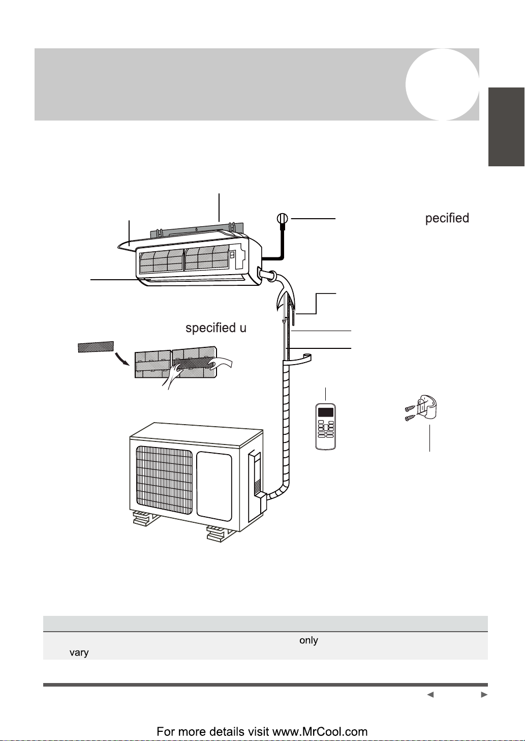
Unit Parts
Wall Mounting Plate
3
Installation
Overview
Front Panel
Louver
Functional Filter
(On Front of Main Filter -
nits)
Power Cable(s units)
Drainage Pipe
Signal Cable
Refrigerant Piping
Remote Control
Remote Holder
(optional)
Fig. 3.1
NOTE ON ILLUSTRATIONS
Illustrations in this manual are for explanatory purposes . The actual shape of your indoor unit
may .
Page 10
Page 11
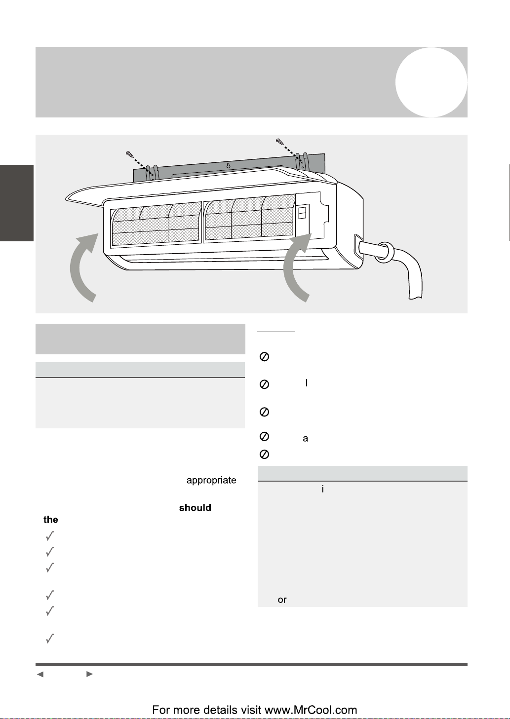
Indoor Unit
Installation
Indoor Unit Installation
4
Installation Instructions - Indoor
Unit
PRIOR TO INSTALLATION
Before installing the indoor unit, refer to the
label on the product box to make sure that the
model number of the indoor unit matches the
model number of the outdoor unit.
Step 1: Select installation location
Before installing the indoor unit, you must
choose an appropriate location. The following
standards will help you choose an
location.
Proper installation locations meet
following standards:
Good air circulation
Convenient drainage
Noise from the unit will not disturb other
people
Firm and solid-the location will not vibrate
Strong enough to support the weight of the
unit
A location at least one meter from all other
electrical devices (e.g., TV, radio, computer)
DO NOT install unit in the following
locations:
Near any source of heat, steam, or
combustible gas
Near f ammable items such as curtains or
clothing
Near any obstacle that might block air
circulation
Near doorway
In a location subject to direct sunlight
NOTE ABOUT WALL HOLE:
If there is no f xed refrigerant piping:
While choosing a location, be aware that you
should leave ample room for a wall hole (see
Drill wall hole for connective piping step)
for the signal cable and refrigerant piping
that connect the indoor and outdoor units.
The default position for all piping is the right
side of the indoor unit (while facing the unit).
However, the unit can accommodate piping to
left right.
Page 11
Page 12
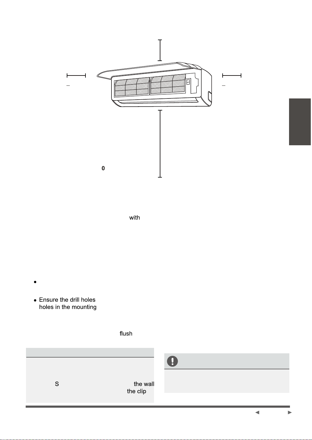
Refer to the following diagram to ensure proper distance from walls and ceiling:
For more details visit www.MrCool.com
Minimum Ceiling
Clearance is
15cm (5.9in)
>12cm
(4.75in)
For Ceilings
Than 9 Foot Suggested
Floor Clearance is
230cm(90.55in)
For Ceilings Less
Than 9 Foot Suggested
Floor Clearance is
2 0cm(78.55in)
Step 2: Attach mounting plate to wall
The mounting plate is the device on which you
will mount the indoor unit.
1. Take out the mounting plate packed
the indoor unit.
2. Place the mounting plate against the wall
in a location that meets the standards in
the Select Installation Location step. (See
Mounting Plate Dimensions for detailed
information on mounting plate sizes.)
3. Drill holes for mounting screws in places that:
Have studs and can support the weight of
the unit
correspond to screw
plate
4. Secure the mounting plate to the wall with
the provided screws.
5. Make sure the mounting plate is against
the wall.
NOTE FOR CONCRETE OR BRICK WALLS:
If the wall is made of brick, concrete, or similar
material, drill 5mm-diameter (0.2in-diameter)
holes in the wall and insert the sleeve anchors
provided.
ecure the mounting plate to
by tightening the screws directly into
anchors.
Greater
>12cm
(4.75in)
Fig. 4.1
Step 3: Drill wall hole for connective piping
You must drill a hole in the wall for refrigerant
piping, the drainage pipe, and the signal cable
that will connect the indoor and outdoor units.
1. Determine the location of the wall hole based
on the position of the mounting plate. Refer
to Mounting Plate Dimensions on the
next page to help you determine the optimal
position. The wall hole should be at least
90mm (3.54in) from the side of the unit, and
at a slightly lower angle to facilitate drainage.
2. Using a 90mm (3.54in) core drill, drill a hole in
the wall. Make sure that the hole is drilled at
a slight downward angle, so that the outdoor
end of the hole is lower than the indoor end
by about 5mm to 7mm (0.2-0.275in). This will
ensure proper water drainage. (See Fig. 4.2)
3. Place the protective wall cuff in the hole. This
protects the edges of the hole and will help
seal it when you finish the installation process.
CAUTION
When drilling the wall hole, make sure to
avoid wires, plumbing, and other sensitive
components.
Indoor Unit
Installation
Page 12
Page 13
Wall
Indoor Outdoor
5-7mm
Indoor Unit
Installation
(0.2-0.3in)
Fig. 4.2
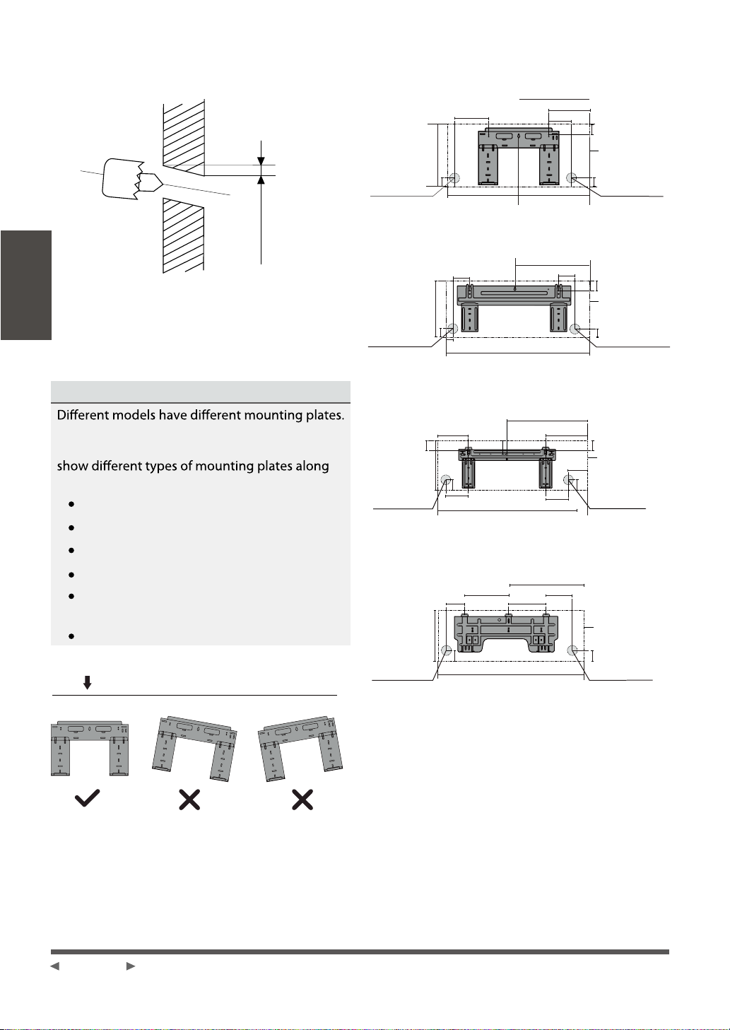
MOUNTING PLATE DIMENSIONS
In order to ensure that you have ample room to
mount the indoor unit, the diagrams to the right
with the following dimensions:
Width of mounting plate
Height of mounting plate
Width of indoor unit relative to plate
Height of indoor unit relative to plate
Recommended position of wall hole (both
to the left and right of mounting plate)
Relative distances between screw holes
Correct orientation of Mounting Plate
Left rear wall
hole 90mm (3.5in)
Left rear wall
hole 90mm (3.5in)
53.5mm
(2.1in)
Left rear wall
hole 90mm (3.5in)
Left rear wall
hole 90mm (3.5in)
192mm (7.55in)
43mm (1.7in)
297mm (11.7in)
138mm (5.45in)
57mm (2.25in)
319mm (12.55in)
34mm
(1.35in)
219mm (8.6in)
47mm (1.85in)
335mm (13.2in)
174.3mm (6.85in)
172mm (6.8in)
362mm (14.25in)
52mm (2.05in)
426mm(16.8in)
802mm (31.6in)
Series 12K Models
517.4mm(20.37in)
965mm (38in)
Series 18K Models
76mm(3in)
1080mm (42.5in)
Series 24K Models
389mm (15.3in)
643.6mm (25.3in)
332mm (13.05in)
1259mm (49.55in)
Series 36K Models
232mm (9.15in)
128mm (5.05in)
144mm (5.65in)
553mm (21.77in)
300mm (11.8in)
151mm (5.95in)
257mm (10.1in)
148.7mm
(5.85in)
47mm (1.85in)
43mm (1.7in)
Indoor unit outline
Right rear wall
43mm (1.7in)
hole 90mm (3.5in)
58mm (2.3in)
Indoor unit outline
Right rear wall
hole 90mm (3.5in)
40mm (1.55in)
53.5mm (2.1in)
Indoor unit outline
Right rear wall
hole 90mm (3.5in)
Indoor unit outline
52mm (2.05in)
Right rear wall
hole 90mm (3.5in)
Page 13
Fig. 4.3
For more details visit www.MrCool.com
Page 14
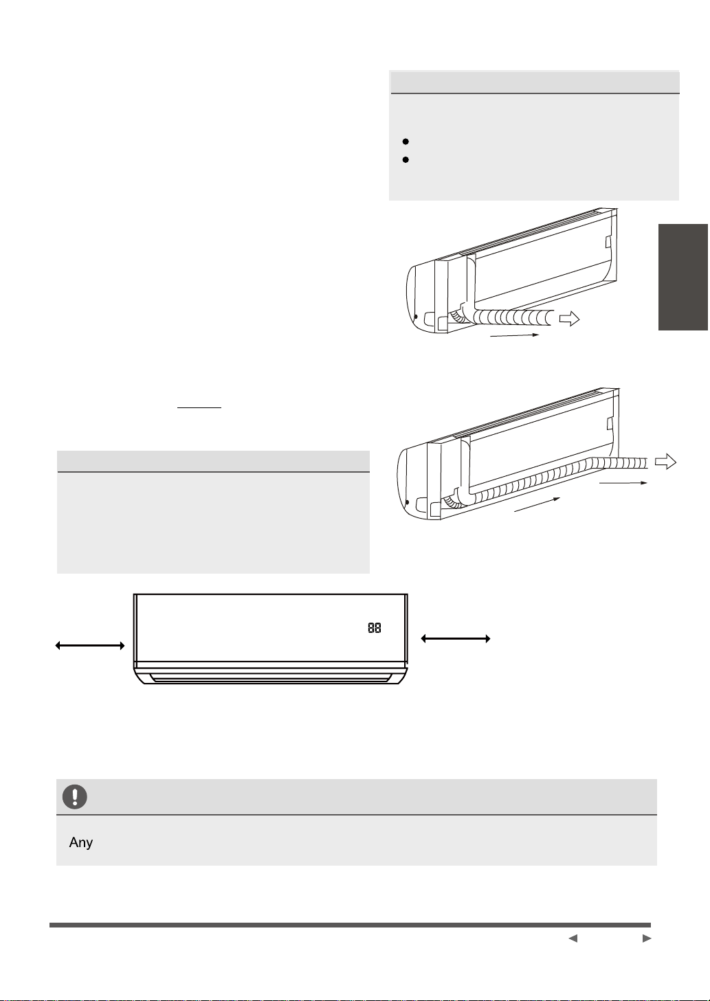
Step 4: Prepare refrigerant piping
The refrigerant piping is inside an insulating
sleeve attached to the back of the unit. You must
prepare the piping before passing it through the
hole in the wall. Refer to the Refrigerant Piping
Connection section of this manual for detailed
instructions on pipe faring and fare torque
requirements, technique, etc.
1. Based on the position of the wall hole relative
to the mounting plate, choose the side from
which the piping will exit the unit.
Connect the indoor refrigerant piping
2.
to the connective piping that will join the
indoor and outdoor units.
Based on the position of the wall hole
3.
relative to the mounting plate, determine the
necessary angle of your piping.
Grip the refrigerant piping at the base of the
4.
bend.
5.
Slowly, with even pressure, bend the piping
towards the hole. Do not dent or damage the
piping during the process.
UNIT IS ADJUSTABLE
NOTE ON PIPING ANGLE
Refrigerant piping can exit the indoor unit from
two different angles:
Left-hand side
Right-hand side
Refer to Fig. 4.4 for details.
Indoor Unit
Installation
Keep in mind that the hooks on the mounting
plate are smaller than the holes on the back
of the unit. If you fnd that you don’t have ample
room to connect embedded pipes to the indoor
unit, the unit can be adjusted left or right by about
30-50mm (1.25-1.95in), depending on the model
30-50mm
(1.2-1.95in)
(1.2-1.95in)
Fig. 4.4
Move to left or right
CAUTION
Be extremely careful not to dent or damage the piping while bending them away from the unit.
dents in the piping will affect performance.
For more details visit www.MrCool.com
Page 14
Page 15
Indoor Unit
Installation
Step 5: Connect drain hose
By default, the drain hose is attached to the lefthand side of unit (when you re facing the back
,
of the unit).
1. To ensure proper drainage, attach the drain
hose on the same side that your refrigerant
piping exits the unit.
2. Attach drain hose extension (purchased
separately) to the end of drain hose.
3. Wrap the connection point firmly with Teflon
tape to ensure a good seal and to prevent
leaks.
4. For the portion of the drain hose that will
remain indoors, wrap it with foam pipe
insulation to prevent condensation.
5. Remove the air filter and pour a small amount
of water into the drain pan to make sure that
water flows from the unit smoothly.
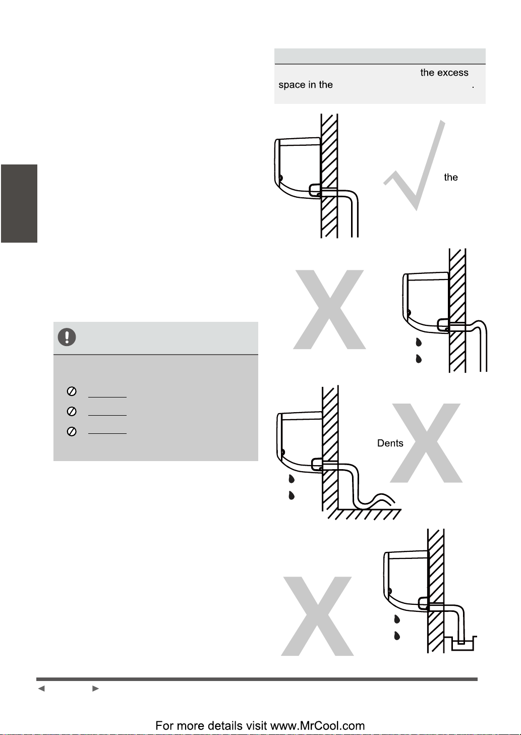
NOTE ON DRAIN HOSE
PLACEMENT
Make sure to arrange the drain hose
according to Fig. 4.5.
DO NOT kink the drain hose.
PLUG THE UNUSED DRAIN HOLE
To prevent leaks you must plug
drain hole with the rubber plug
.
CORRECT
Make sure there are no
kinks or dent in drain
hose to ensure proper
drainage.
Fig.4.5
NOT CORRECT
Kinks in the drain hose
will create water traps.
Fig. 4.6
Page 15
DO NOT create a water trap.
DO NOT put the end of drain hose in
water or a container that will collect
water.
NOT CORRECT
in the drain hose
will create water traps.
Fig. 4.7
NOT CORRECT
Do not place the end
of the drain hose in
water or in containers
that collect water. This
will prevent proper
drainage.
Fig. 4.8
Page 16
BEFORE PERFORMING ELECTRICAL WORK, READ THESE REGULATIONS
1. All wiring must comply with local and national electrical codes, and must be installed by a
licensed electrician.
2. All electrical connections must be made according to the Electrical Connection Diagram
located on the panels of the indoor and outdoor units.
3. If there is a serious safety issue with the power supply, stop work immediately. Explain your
reasoning to the client, and refuse to install the unit until the safety issue is properly resolved.
4. Power voltage should be within 90-100% of rated voltage. Insufficient power supply can
cause malfunction, electrical shock, or fire.
5. If connecting power to fixed wiring, install a surge protector and main power switch with a
capacity 1.5 times the maximum
6. If connecting power to fixed wiring, a switch or circuit breaker that disconnects all poles and
has a contact separation of at least 1/8in (3mm) must be incorporated in the fixed wiring.
se an approved circuit breaker or switch.
7. Only connect the unit to an individual branch circuit outlet. Do not connect another appliance
to that outlet.
8. Make sure to properly ground the air conditioner.
9. Every wire must be firmly connected. Loose wiring can cause the terminal to overheat,
resulting in malfunction and possible fire.
current.
Indoor Unit
Installation
10. Do not let wires touch or rest against refrigerant tubing, the compressor, or any moving parts
within the unit.
11. If the unit has an auxiliary electric heater, it must be installed at least 1 meter (40in) away
from combustible materials.
WARNING
BEFORE PERFORMING ANY ELECTRICAL OR WIRING WORK, TURN OFF THE MAIN POWER
TO THE SYSTEM.
Page 16
Page 17
Step 6: Connect indoor power wire
For more details visit www.MrCool.com
The cable enables communication between
the indoor and outdoor units. You must first
choose the right cable size before preparing it for
connection.
Cable Types
Indoor Power Cable (if applicable):
H05VV-F or H05V2V2-F
Outdoor Power Cable: H07RN-F
Indoor Unit
Installation
Signal Cable: H07RN-F
Minimum Cross-Sectional Area of
Power and Signal Cables
North America
Model Series
12K & 18K
24K
36K
Appliance
Amps (A)
20 12
25
35
AWG
10
8
TAKE NOTE OF FUSE SPECIFICATIONS
The air conditioner s circuit board (PCB) is
,
designed with a fuse to provide overcurrent
protection. The specifcations of the fuse
are printed on the circuit board, such as:
T3.15A/250VAC, T5A/250VAC, etc.
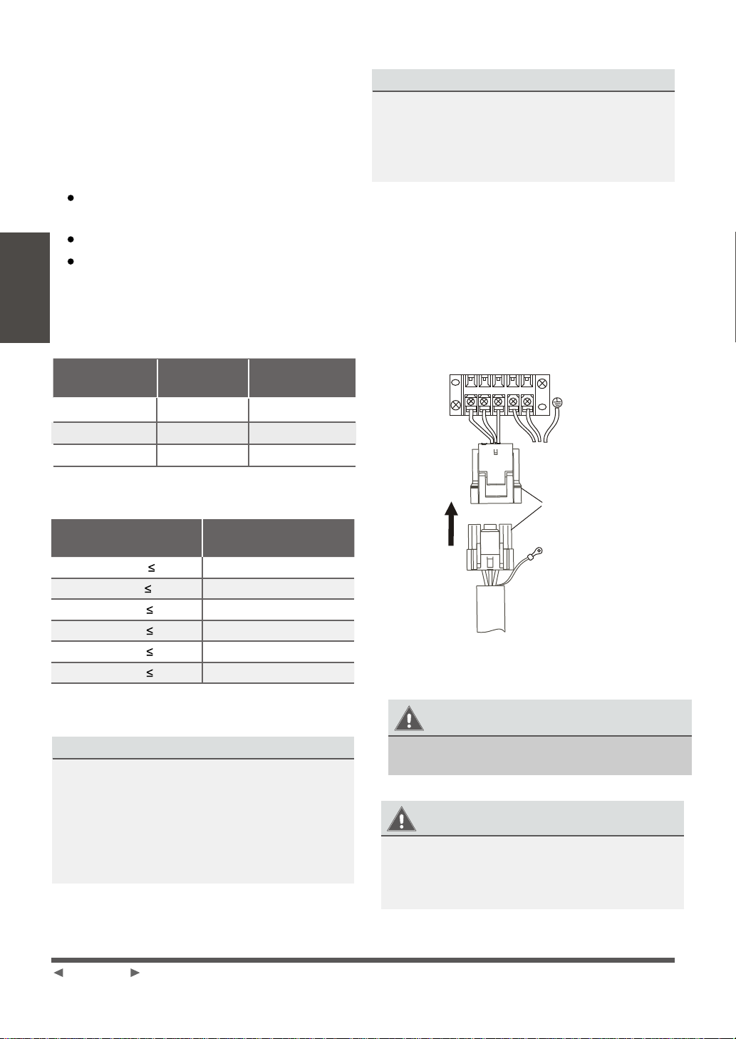
1. Prepare the cable for connection:
Hold the indoor plug connector and insert the
mating plug connector located on the outdoor
unit until it fixed with a clicking sound. The Y/G
wire should be connected individually. Secure
the cable onto the control board with the cord
clamp. See Fig.4.9 for example:
Outdoor unit
L N1
2
3
Power
supply
Other Regions
Rated Current of
Appliance (A)
> 3 and 6 0.75
> 6 and 10
> 10 and 16 1.5
> 16 and 25 2.5
> 25 and 32 4
> 32 and 40 6
NominalCro ss Sectional
-
Area (mm )
2
1.0
CHOOSE THE RIGHT CABLE SIZE
The size of the power supply cable, signal
cable, fuse, and switch needed is determined
by the maximum current of the unit. The
maximum current is indicated on the nameplate
located on the side panel of the unit. Refer to
this nameplate to choose the right cable, fuse,
or switch.
Connector
Y/G
Indoor unit
Fig. 4.9
NOTE ABOUT WIRING
THE WIRING CONNECTION PROCESS MAY
DIFFER SLIGHTLY BETWEEN UNITS
WARNING
ALL WIRING MUST PERFORMED STRICTL
IN ACCORDANCE WITH THE WIRING
DIAGRAM LOCATED ON THE INSIDE OF THE
INDOOR UNIT S WIRE COVER.
,
Page 17
Page 18
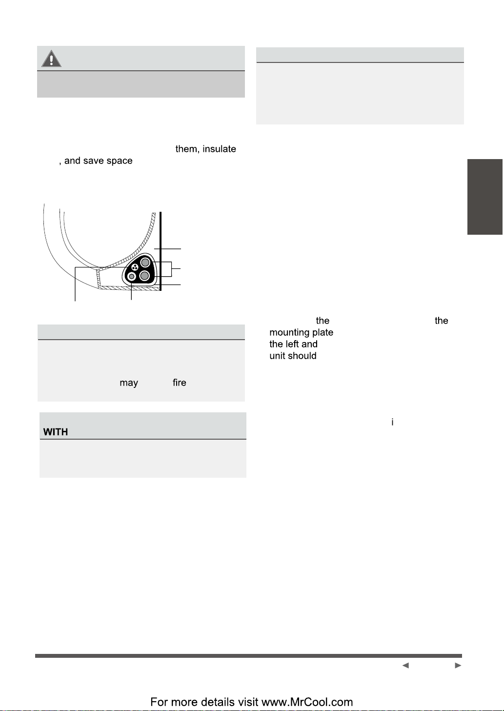
NOTE ABOUT WIRING
THE WIRING CONNECTION PROCESS MAY
DIFFER SLIGHTLY BETWEEN UNITS
Step 7: Wrap piping and cables
Before passing the piping, drain hose, and the
signal cable through the wall hole, you must
bundle them together to protect
them .
1. Bundle the drain hose, refrigerant pipes, and
signal cable according to Fig. 4.10.
Indoor Unit
Space behind unit
Refrigerant piping
Insulation tape
Signal wire
DRAIN HOSE MUST BE ON BOTTOM
Make sure that the drain hose is at the bottom
of the bundle. Putting the drain hose at the
top of the bundle can cause the drain pan
to overfow, which lead to or water
damage.
DO NOT INTERTWINE SIGNAL CABLE
OTHER WIRES
While bundling these items together, do not
intertwine or cross the signal cable with any
other wiring.
2. Using adhesive vinyl tape, attach the drain
hose to the underside of the refrigerant pipes.
3. Using insulation tape, wrap the signal wire,
refrigerant pipes, and drain hose tightly
together. Double-check that all items are
bundled in accordance with Fig. 4.10
Drain hose
Fig. 4.10
DO NOT WRAP ENDS OF PIPING
When wrapping the bundle, keep the ends
of the piping unwrapped. You need to access
them to test for leaks at the end of the
installation process (refer to Electrical Checks
and Leak Checks section of this manual).
Step 8: Mount indoor unit
If you installed new connective piping to the
outdoor unit, do the following:
1. If you have already passed the refrigerant
piping through the hole in the wall, proceed
to Step 4.
2. Otherwise, double-check that the ends of the
refrigerant pipes are sealed to prevent dirt or
foreign material from entering the pipes.
3. Slowly pass the wrapped bundle of refrigerant
pipes, drain hose, and signal wire through the
hole in the wall.
4. Hook the top of the indoor unit on the upper
hook of the mounting plate.
5. Check that unit is hooked firmly on
by applying slight pressure to
right-hand sides of the unit. The
not jiggle or shift.
6. Using even pressure, push down on the
bottom half of the unit. Keep pushing down
until the unit snaps onto the hooks along the
bottom of the mounting plate.
7. Again, check that the unit is f rmly mounted
by applying slight pressure to the left and the
right-hand sides of the unit.
Indoor Unit
Installation
Page 18
Page 19
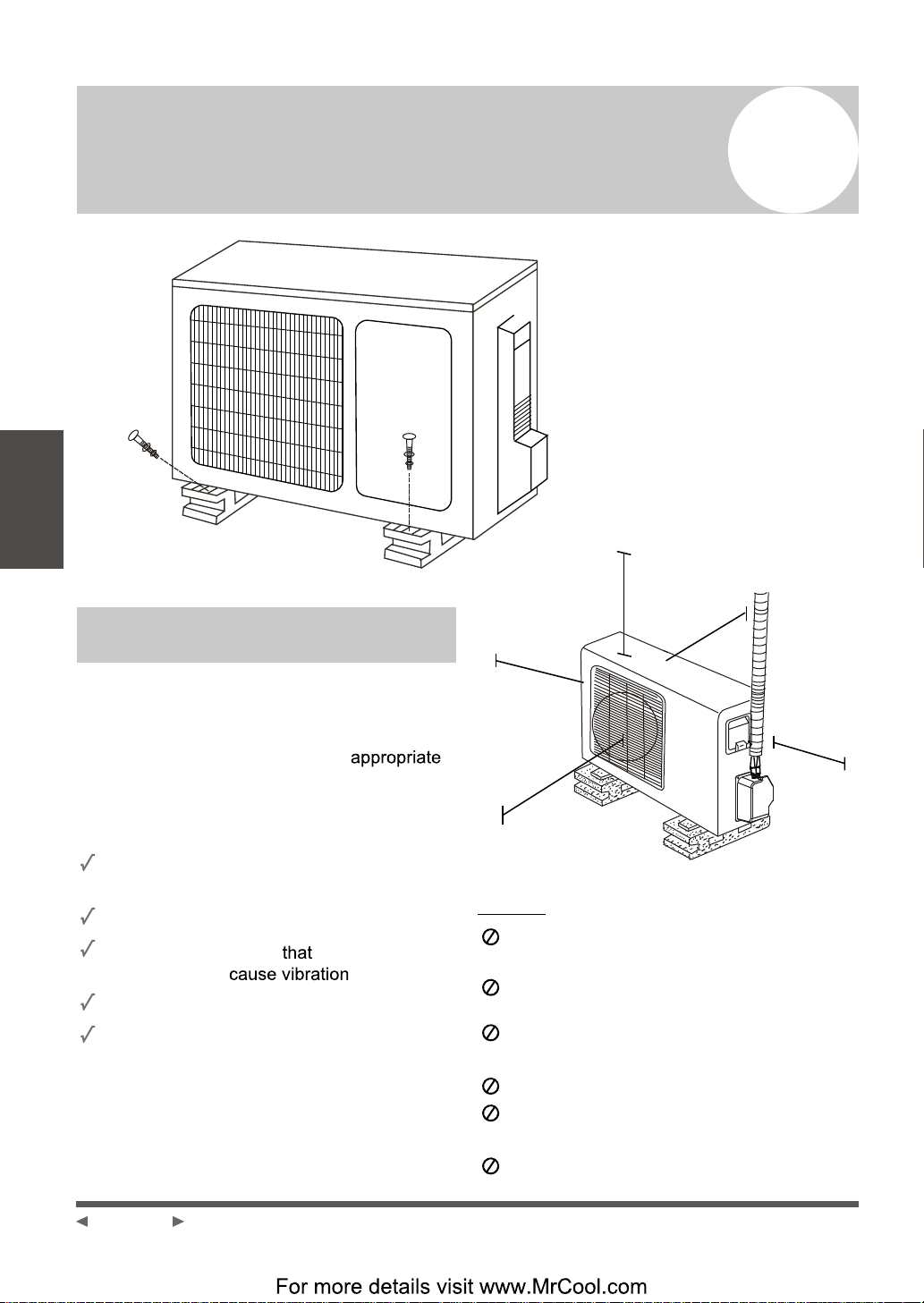
Outdoor Unit
Installation
Outdoor Unit Installation
5
Installation Instructions- Outdoor
Unit
Step 1: Select installation location
Before installing the outdoor unit, you must
choose an appropriate location. The following
standards will help you choose an
location.
Proper installation locations meet the
following standards:
Meets all spatial requirements shown in
Installation Space Requirements (Fig. 4.1)
Good air circulation and ventilation
Firm and solid location
unit and will not
Noise from the unit will not disturb others
Protected from prolonged periods of direct
sunlight or rain
can support the
30cm (12in)
on left
200cm (79in)
in front
DO NOT install unit in the following locations:
Near an obstacle that will block air inlets
and outlets
Near a public street, crowded areas, or
where noise from the unit will disturb others
Near animals or plants that will be harmed
by hot air discharge
Near any source of combustible gas
In a location that is exposed to large
amounts of dust
In a location exposed to a excessive amounts
of salty air
6 c0 ni42( m ba ) evo
30cm (12in)
from back wall
60cm (24in)
on right
C
Fig. 5.1
Page 19
Page 20
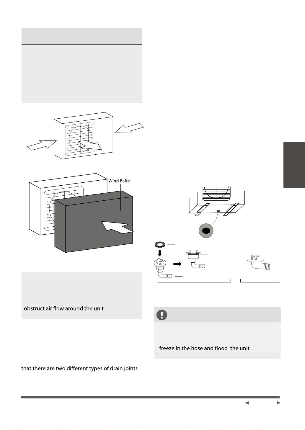
SPECIAL CONSIDERATIONS FOR
For more details visit www.MrCool.com
EXTREME WEATHER
If the unit is exposed to heavy wind:
Install unit so that air outlet fan is at a 9
angle to the direction of the wind. If needed,
o
0
build a barrier in front of the unit to protect it
from extremely heavy winds.
See Fig. 4.2 and Fig. 4.3 below.
Strong wind
Strong wind
Fig. 4.2
If the drain joint comes with a rubber seal
(see Fig. 4.4 - A), do the following:
1. Fit the rubber seal on the end of the drain joint
that will connect to the outdoor unit.
2. Insert the drain joint into the hole in the base
pan of the unit.
3. Rotate the drain joint 90° until it clicks in place
facing the front of the unit.
4. Connect a drain hose extension (not included)
to the drain joint to redirect water from the
unit during heating mode.
If the drain joint doesn t come with a rubber
seal (see Fig.
4.4 - B), do the following:
,
1. Insert the drain joint into the hole in the base
pan of the unit. The drain joint will click in
place.
2. Connect a drain hose extension (not included)
to the drain joint to redirect water from the
unit during heating mode.
Outdoor Unit
Installation
Strong wind
Fig. 4.3
If the unit is frequently exposed to heavy
rain or snow:
Build a shelter above the unit is to protect
it from the rain or snow. Be careful not to
Step 2: Install drain joint
Heat pump units require a drain joint. Before
bolting the outdoor unit in place, you must install
the drain joint at the bottom of the unit. Note
depending on the type of outdoor unit.
Base pan hole of
outdoor unit
Seal
Seal
Drain joint
(A) (B)
Fig. 4.4
IN COLD CLIMATES
In cold climates, make sure that the drain hose
is as vertical as possible to ensure swift water
drainage. If water drains too slowly, it can
Page 20
Page 21
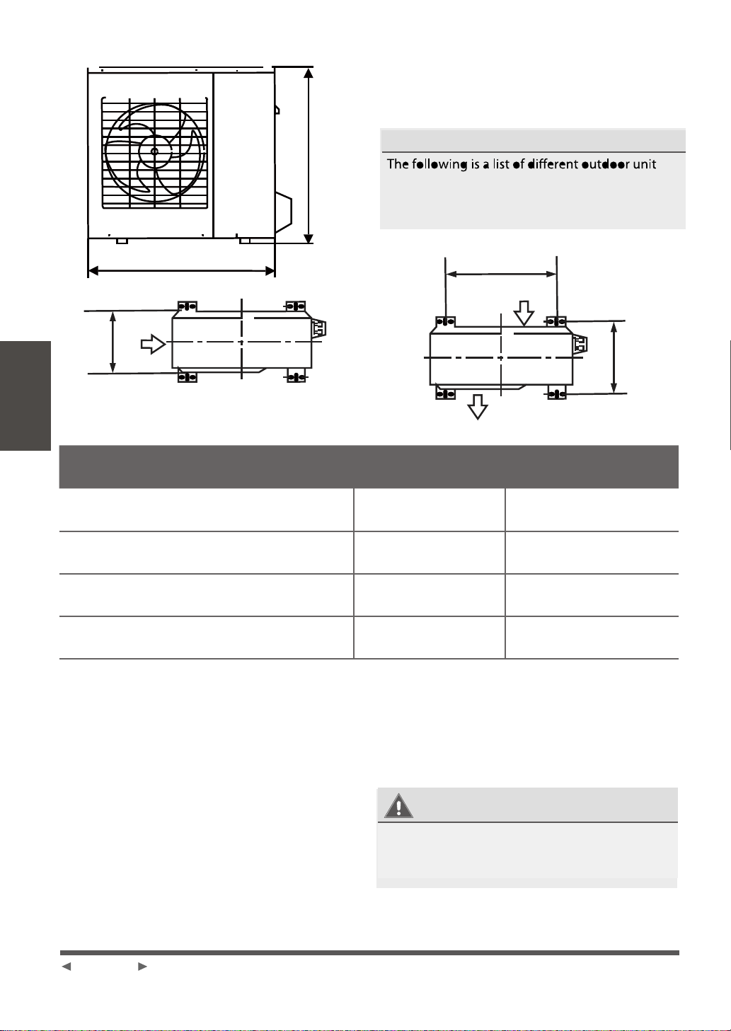
H
Step 3: Anchor outdoor unit
The outdoor unit can be anchored to the ground
or to a wall-mounted bracket.
UNIT MOUNTING DIMENSIONS
sizes and the distance between their mounting
feet. Prepare the installation base of the unit
according to the dimensions below.
Outdoor Unit
Installation
W
Air Inlet
D
Outdoor Unit Dimensions (inches)
Width (W) x Height (H) x Depth (D)
30.7 x 21.25 x 9.85 (inches)
DIY-12-HP-C-115A
DIY-18-HP-C-230A
DIY-24-HP-C-230A
DIY-36-HP-C-230A
779.8 x 540 x 251 (mm)
31.9 x 22 x 12.2 (inches)
810 x 559 x 310 (mm)
33.25 x 27.5 x 12.6 (inches)
844.5 x 698 x 320 (mm)
37.2 x 31.9 x 15.55 (inches)
945 x 810 x 395 (mm)
Fig. 4.5
A
Air Inlet
Air Outlet
Mounting Dimensions (inches)
Width (A) Depth (B)
21.6 in.
548.6 mm
21.6 in.
548.6 mm
22 in.
558.8 mm
25.2 in.
640 mm
10.85 in.
275.6 mm
12.8 in.
325.12 mm
13.2 in.
335 mm
15.95 in.
405 mm
B
If you will install the unit on the ground or
on a concrete mounting platform, do the
following:
1. Mark the positions for four expansion bolts
based on dimensions in the Unit Mounting
Dimensions chart.
2. Pre-drill holes for expansion bolts.
3. Clean concrete dust away from holes.
4. Place a nut on the end of each expansion bolt.
5. Hammer expansion bolts into the pre-drilled
holes.
Page 21
For more details visit www.MrCool.com
6. Remove the nuts from expansion bolts, and
place outdoor unit on bolts.
7. Put washer on each expansion bolt, then
replace the nuts.
8. Using a wrench, tighten each nut until snug.
WARNING
WHEN DRILLING INTO CONCRETE, EYE
PROTECTION IS RECOMMENDED AT ALL
TIMES.
Page 22
If you install the unit on a wall-mounted
bracket, do the following:
CAUTION
Before installing a wall-mounted unit, make
sure that the wall is made of solid brick,
concrete, or of similarly strong material. The
wall must be able to support at least four
times the weight of the unit.
1. Mark the position of bracket holes based on
dimensions in the Unit Mounting Dimensions
chart.
2. Pre-drill the holes for the expansion bolts.
3. Clean dust and debris away from holes.
4. Place a washer and nut on the end of each
expansion bolt.
5. Thread expansion bolts through holes in
mounting brackets, put mounting brackets
in position, and hammer expansion bolts into
the wall.
6. Check that the mounting brackets are level.
7. Carefully lift unit and place its mounting feet
on brackets.
8. Bolt the unit firmly to the brackets.
TO REDUCE VIBRATIONS OF WALLMOUNTED UNIT
If allowed, you can install the wall-mounted
unit with rubber gaskets to reduce vibrations
and noise.
Step 4: Connect signal and power cables
The outside unit s terminal block is protected by
an electrical wiring cover on the side of the unit.
A comprehensive wiring diagram is printed on
the inside of the wiring cover.
,
BEFORE PERFORMING
ELECTRICAL WORK,
READ THESE REGULATIONS
1. All wiring must comply with local and
national electrical codes, and must be
installed by a licensed electrician.
2. All electrical connections must be made
according to the Electrical Connection
Diagram located on the side panels of the
indoor and outdoor units.
3. If there is a serious safety issue with the
power supply, stop work immediately. Explain
your reasoning to the client, and refuse
to install the unit until the safety issue is
properly resolved.
4. Power voltage should be within 90-100% of
rated voltage. Insuffcient power supply can
cause electrical shock or fire.
5. If connecting power to fixed wiring, install
a surge protector and main power switch
with a capacity of 1.5 times the maximum
current of the unit.
6. If connecting power to f xed wiring, a switch
or circuit breaker that disconnects all poles
and has a contact separation of at least 1/8in
(3mm) must be incorporated in the fixed
wiring. The qualifed technician must use an
approved circuit breaker or switch.
7. Only connect the unit to an individual branch
circuit outlet. Do not connect another
appliance to that outlet.
8. Make sure to properly ground the air
conditioner.
9. Every wire must be firmly connected. Loose
wiring can cause the terminal to overheat,
resulting in product malfunction and possible
fire.
10. Do not let wires touch or rest against
refrigerant tubing, the compressor, or any
moving parts within the unit.
11. If the unit has an auxiliary electric heater, it
must be installed at least 1 meter (40in) away
from any combustible materials.
Outdoor Unit
Installation
Page 22
Page 23
Refrigerant Piping Connection
6
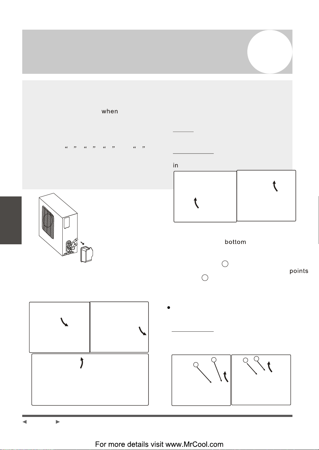
Connecting the refrigerant pipe to
outdoor unit
CAUTION: For your safet, always wear
goggles and work gloves
the pipes.
NOTE: To distinguish the connectors to be
connected to the indoor unit and outdoor unit,
the connectors of the refrigerant pipe has
been labelled A,B,Cand D .
Ensure the marks on the connector are the
same to the indoor s and outdoor s
respectively during connection.
1. First remove the water tray on the
outdoor unit as shown in Fig.6.1.
Refrigerant
Connection
Piping
2. Do not remove the plastic seals from the
outdoor unit and the appropriate
refrigerant pipes until immediately before
you connect them, Fig.6.2
,
Fig.6.1
connecting
,
3. Align the refrigerant pipes correctly so
that they line up with the valves and are
not stressed. Place the screw connector
on the refrigerant line just on to the thread
on the outdoor unit and tighten the first few
threads by hand, Fig.6.3.
NOTE: The refrigerant pipes must be
connected to the valves on the outdoor unit
with as little stress as possible.
IMPORTANT: Before you continue, it is
essential that you read the following
structions carefully.
Fig.6.3
4. Now tighten the screw connector
first and then the top screw connector
using the open-ended spanner.
points marked using an open-ended
spanner and turn the nuts only at the
marked using an open-ended spanner
(Select the appropriate spanner according
to the dimensions of the connector),
see Fig.6.4
Ensure that the screw connectors do not
skew as you tighten them and work quickly.
See the next page for the proper torque.
IMPORTANT: Since the coupling works
with tapping rings, it may leak if you undo
and reconnect the pipes. This will also void
the warranty.
,,
,,
2
1
,,
,,
1
2
2
1
Hold the
Page 23
Fig.6.2
Fig.6.4
Page 24
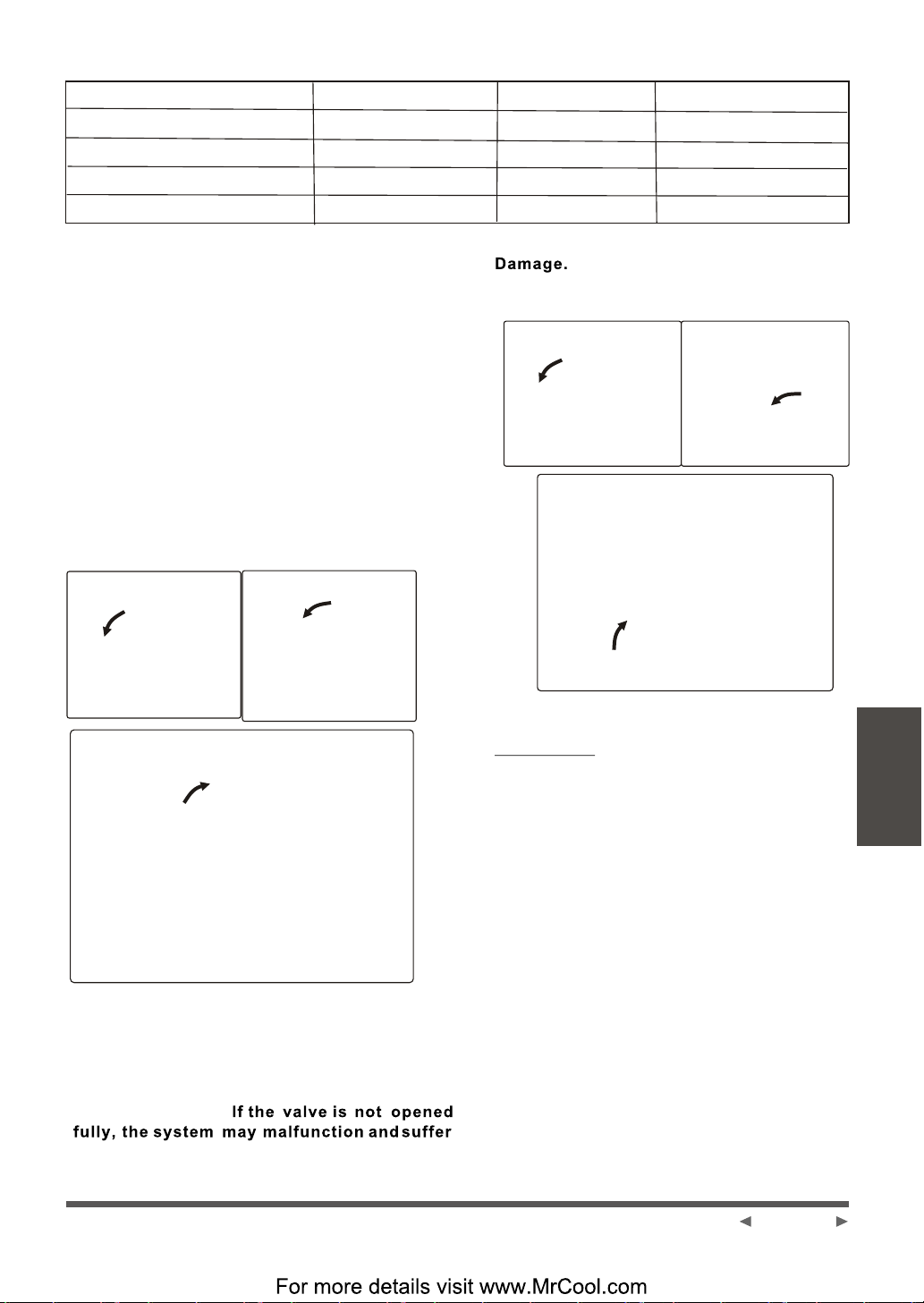
Coupling size (last 2 part numbers)
-06(9.5mm dash size)
-08(12.7mm dash size)
-12(19.1mm dash size)
-16(25.4mm dash size)
Pound-force foot(1bf-ft)
18 - 20
30 - 35
45 - 50
60 - 65
Newton meter(N-m)
24.4 - 27.1
40.6 - 47.4
61.0 - 67.7
81.3 - 88.1
Kilogram-force meter(kgf-m)
2.4 - 2.7
4.1 - 4.8
6.2 - 6.9
8.2 - 8.9
After completing steps 1- 4, check that all
the connections are sealed correctly using
leak detection spray or soap suds. If any
bubbles form,the system has a leak and the
screw connectors must be retightened
using an open-ended spanner.
5. Now remove the cover on the top valve
using a 19 mm open-ended spanner. Open
the valve by turning it counter-clockwise as
far as it will go using a 5 mm Allen key. The
valve is now open. If the valve is not opened
fully, the system may malfunction and suffer
damage. Screw the cover back on to the top
valve and tighten it well to ensure that it is
properly sealed. See Fig.6.5.
Fig.6.5
6. Now remove the cover on the bottom valve
using a 19 mm open-ended spanner. Open
the valve b
turning it counter-clockwise as
y
far as it will go using a 5 mm Allen key. The
valve is now open.
Screw the cover back on to the
bottom valve and tighten it well to ensure
that it is properly sealed. See Fig.6.6.
Fig.6.6
Important! The conical ring on the valve
has an important sealing function together
with the sealing seat in the caps. Ensure
that you do not damage the cone and that
you keep the cap free of dirt and dust.
7. After completing steps 1- 6, check that all
the connections are sealed correctly using
leak detection spray or soap suds. If any
bubbles form, the system has a leak and
the screw connectors must be retightened
using an open- ended spanner.
8. Start the equipment so that the operating
pressures build up inside it. Check all the
connectors again for signs of leaks
a) during cooling mode
b) in heating mode.
If any bubbles form, the system has a leak
and the screw connectors must be
retightened using an open-ended spanner.
Connection
Piping
Page 24
Page 25
Electrical and Gas Leak Checks
7
Electrical Safety Checks
After installation, confirm that all electrical wiring
is installed in accordance with local and national
regulations, and according to the Installation
Manual.
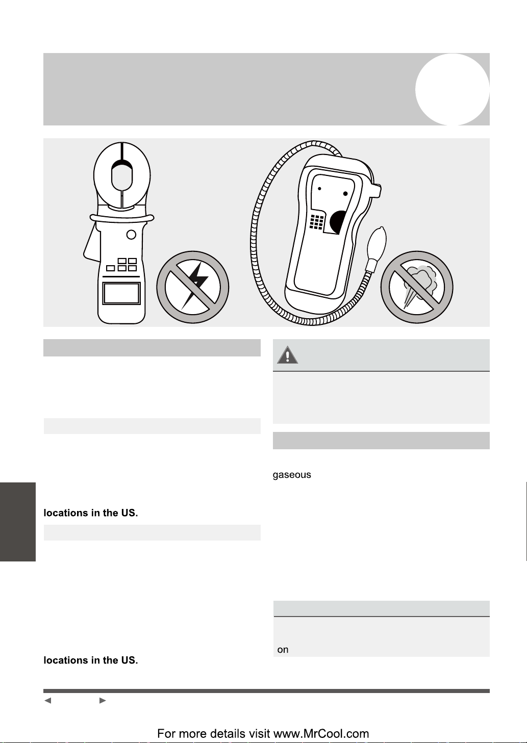
BEFORE TEST RUN
Check Grounding Work
Measure grounding resistance by visual detection
and with grounding resistance tester. Grounding
resistance must be less than 4.
Electrical and Gas
Leak Checks
Note: This may not be required for some
DURING TEST RUN
Check for Electrical Leakage
During the Test Run, use an electroprobe and
multimeter to perform a comprehensive electrical
leakage test.
If electrical leakage is detected, turn off the unit
immediately and call a licensed electrician to find
and resolve the cause of the leakage.
Note: This may not be required for some
WARNING - RISK OF
ELECTRIC SHOCK
ALL WIRING MUST COMPLY WITH LOCAL
AND NATIONAL ELECTRICAL CODES,
AND MUST BE INSTALLED BY A LICENSED
ELECTRICIAN.
Gas Leak Checks
There are two different methods to check for
leaks.
Soap and Water Method
Using a soft brush, apply soapy water or liquid
detergent to all pipe connection points on the
indoor unit and outdoor unit. The presence of
bubbles indicates a leak.
Leak Detector Method
If using leak detector, refer to the device s
operation manual for proper usage instructions.
AFTER PERFORMING GAS LEAK CHECKS
After confrming that the all pipe connection
points DO NOT leak, replace the valve cover
the outside unit.
,
Page 25
Page 26
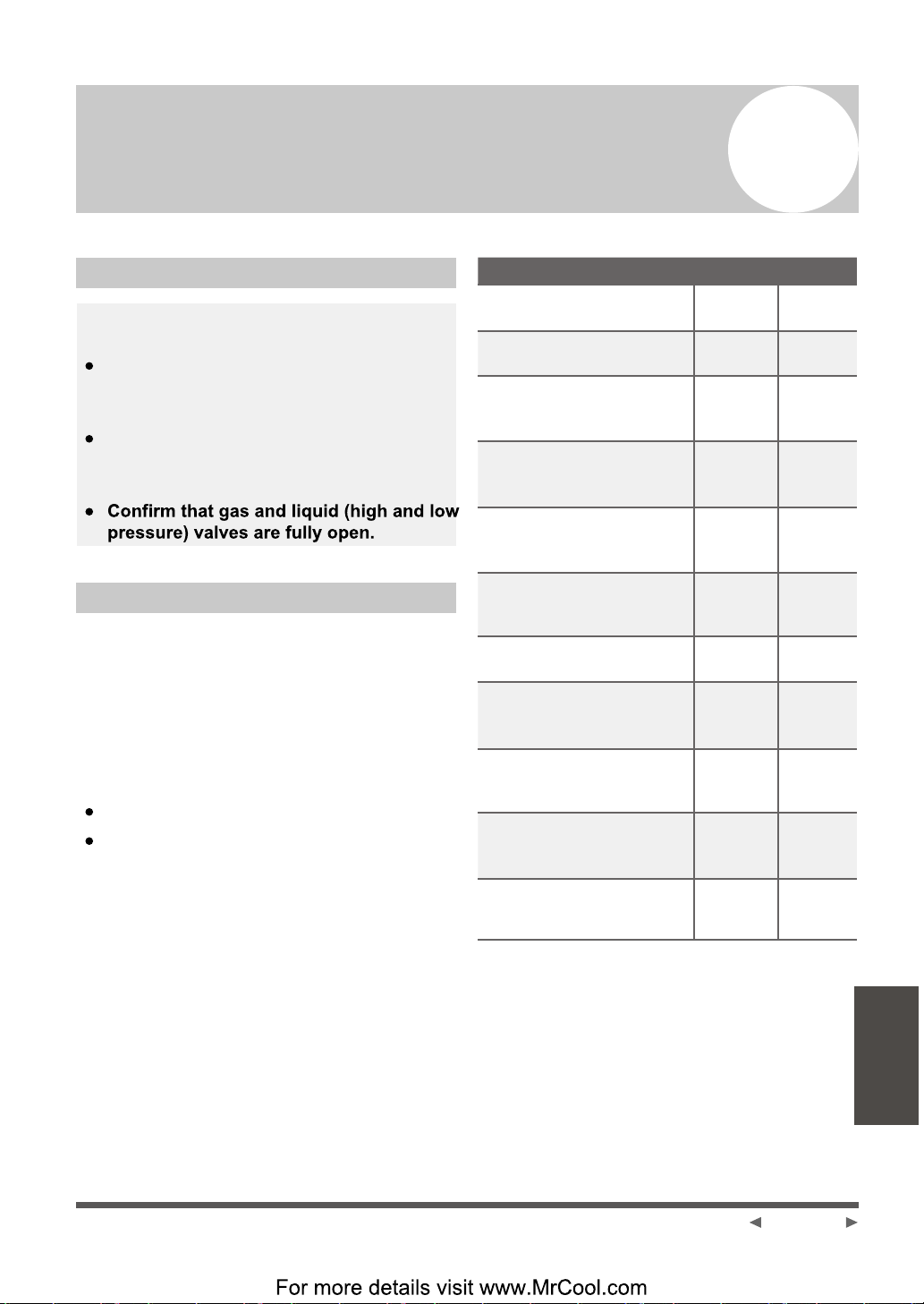
Test Run
8
Before Test Run
Only perform test run after you have completed
the following steps:
Electrical Safety Checks - Confirm that
the unit s electrical system is safe and
operating properly.
Gas Leak Checks - Check all fare nut
connections and confirm that the system is
not leaking.
,
Test Run Instructions
You should perform the Test Run for at least 30
minutes.
1. Connect power to the unit.
2. Press the ON/OFF button on the remote
controller to turn it on.
3. Press the MODE button to scroll through the
following functions, one at a time:
COOL - Select lowest possible temperature
HEAT - Select highest possible temperature
4. Let each function run for 5 minutes, and
perform the following checks:
List of Checks to Perform PASS/FAIL
No electrical leakage
Unit is properly grounded
All electrical terminals
properly covered
Indoor and outdoor units
are solidly installed
All pipe connection
points do not leak
Water drains properly
from drain hose
All piping is properly
insulated
Unit performs COOL
function properly
Unit performs HEAT
function properly
Indoor unit louvers
rotate properly
Indoor unit responds to
remote controller
Outdoor
(2):
Indoor
(2):
Page 26
Test Run
Page 27
DOUBLE-CHECK PIPE CONNECTIONS
For more details visit www.MrCool.com
During operation, the pressure of the
refrigerant circuit will increase. This may
reveal leaks that were not present during your
initial leak check. Take time during the Test
Run to double-check that all refrigerant pipe
connection points do not have leaks. Refer to
Gas Leak Check section for instructions.
5. After the Test Run is successfully complete,
and you confirm that all checks points in List
of Checks to Perform have PASSED, do the
following:
a. Using remote control, return unit to
normal operating temperature.
b. Using insulation tape, wrap the indoor
refrigerant pipe connections that you
left uncovered during the indoor unit
installation process.
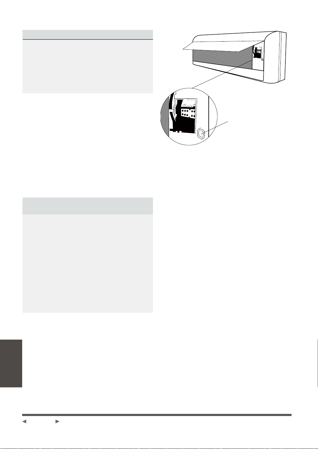
Manual control button
Fig.8.1
IF AMBIENT TEMPERATURE IS BELOW
o
63 F
You can t use the remote control to turn
on the COOL function when the ambient
temperature is below 63 F. In this instance,
,
o
you can use the MANUAL CONTROL button
to test the COOL function.
1. Lift the front panel of the indoor unit, and
raise it until it clicks in place.
2. The MANUAL CONTROL button is located
on the right-hand side of the unit. Press it 2
times to select the COOL function. See
Fig.8.1.
3. Perform Test Run as normal.
Test Run
Page 27
Page 28
E Disposal Guidelines
9
This appliance contains refrigerant and other potentially hazardous materials. When disposing of
this appliance, the law requires special collection and treatment. Do not dispose of this product as
household waste or unsorted municipal waste.
When disposing of this appliance you have the following options:
Dispose of the appliance at designated municipal electronic waste collection facility.
When buying a new appliance, the retailer will the old appliance free of charge.
The manufacturer will the old appliance free of charge.
Sell the appliance to certified scrap metal dealers.
Special notice
Disposing of this appliance in the forest or other natural surroundings endangers your health and is
bad for the environment. Hazardous substances may leak into the ground water and enter the food
chain.
Page 28
Information
Disposal
Page 29
DIY Series
 Loading...