

Page 1

The Signature Series is NOT designed for amateur installation. Installation SHOULD be performed by an authorized technician.
Please read this manual carefully before installation and keep it for future reference.
Owner & Installation
Manual
Signature Series
MAHM*CTA AIR Handler
The Signature Series is NOT designed for amateur installation. Installation SHOULD be performed by an authorized technician.
Please read this manual carefully before installation and keep it for future reference.
Page 2

INSTALLATION INSTRUCTIONS
MAHM*CTA Series Air Handler
This manual must be left with the homeowner for future reference.
This is a safety alert symbol and should never be ignored. When you see this symbol on labels or in
manuals, be alert to the potential for personal injury or death.
Table of Contents
Shipping and Packing List ...........................................3
General........................................................................3
Requirements ..............................................................3
Installation Clearances ................................................4
Installation ...................................................................4
Condensate Drain........................................................7
Duct System and Filters ..............................................8
Brazing Refrigerant Lines............................................9
Sealing the Unit .........................................................12
Electrical Connections...............................................12
..............................16
Check-Out Procedures..............................................18
Operation...................................................................18
..........................................19
Repairing or Replacing Cabinet Insulation ................19
Professional Maintenance .........................................20
Use of Air Handler During Construction.....................20
......2
IMPORTANT INFORMATION FOR INSTALLER
This unit has a delay relay that delays the supply blower “ON” for 1 second and keeps the blower “ON” for 45
seconds on all fan and cooling demands. For more details, refer to page 18 for unit sequence of operation.
3 4
100%
2
1
1
SECOND
DELAY
Manufactured By
MRCOOL LLC
Hickory, KY 42051
Save these instructions for future reference
507787-01C mrcool.com Page 1 of 22
CFM
COOLING
DEMAND
100%
CFM
45
SECS
OFF
*P507787-C*1
(P) 507787-01C
Page 3
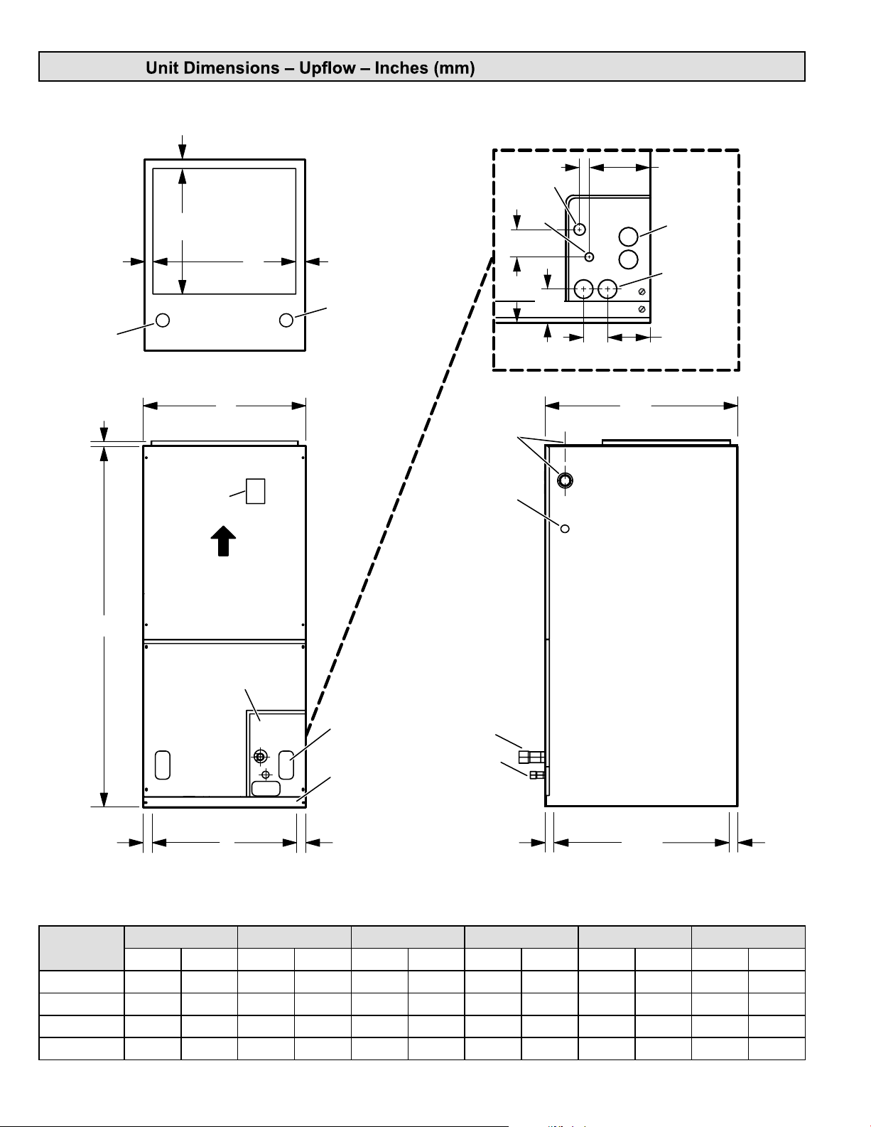
MAHM*CTA
1 (25)
LINE VOLTAGE
INLETS
(Top and Left Side)
3/4
(19)
1 (25)
14-1/2
(368)
TOP VIEW
CIRCUIT
BREAKER
COVER
SUPPLY AIR
OPENING
C
B
1 (25)
LOW VOLTAGE
INLETS
(Top and Right Side)
2-3/8
(60)
4-3/8
(111)
LINE VOLTAGE
INLETS
(Top and Right Side)
LOW VOLTAGE
INLETS
(Either Side)
DETAIL OF PIPING PLATE
3/4 (19)
SUCTION
LINE
LIQUID
LINE
2-3/4
(70)
1-3/4
(44)
4-3/4
(121)
CONDENSATE
CONDENSATE
3-1/2
(89)
22
(559)
DRAINS (2)
(Horizontal)
DRAINS (2)
(Upflow and
Downflow)
AIR FLOW
A
PIPING
PLATE
1-1/8
(29)
D
OPENING
CONDENSATE DRAIN
PIPING PLATE (3)
(2-1/4 x 3-3/4)
FILTER
ACCESS
1-1/8
(29)
SUCTION
LINE
LIQUID
LINE
1/2
(13)
20-3/8
(518)
OPENING
FRONT VIEW SIDE VIEW
Dimensions
018 024 030 036 / 042 048 060
in. mm in. mm in. mm in. mm in. mm in. mm
A 43-1/2 1105 45-1/2 1156 47 1194 53-5/8 1362 55 1397 59-3/4 1518
B 18-1/2 470 18-1/2 470 18-1/2 470 21-1/2 546 21-1/2 546 21-1/2 546
C 16-1/2 419 16-1/2 419 16-1/2 419 19-1/2 495 19-1/2 495 19-1/2 495
D 16-1/4 413 16-1/4 413 16-1/4 413 19-1/4 489 19-1/4 489 19-1/4 489
1-1/8
(29)
507787-01Cmrcool.comPage 2 of 22
Page 4
Shipping and Packing List
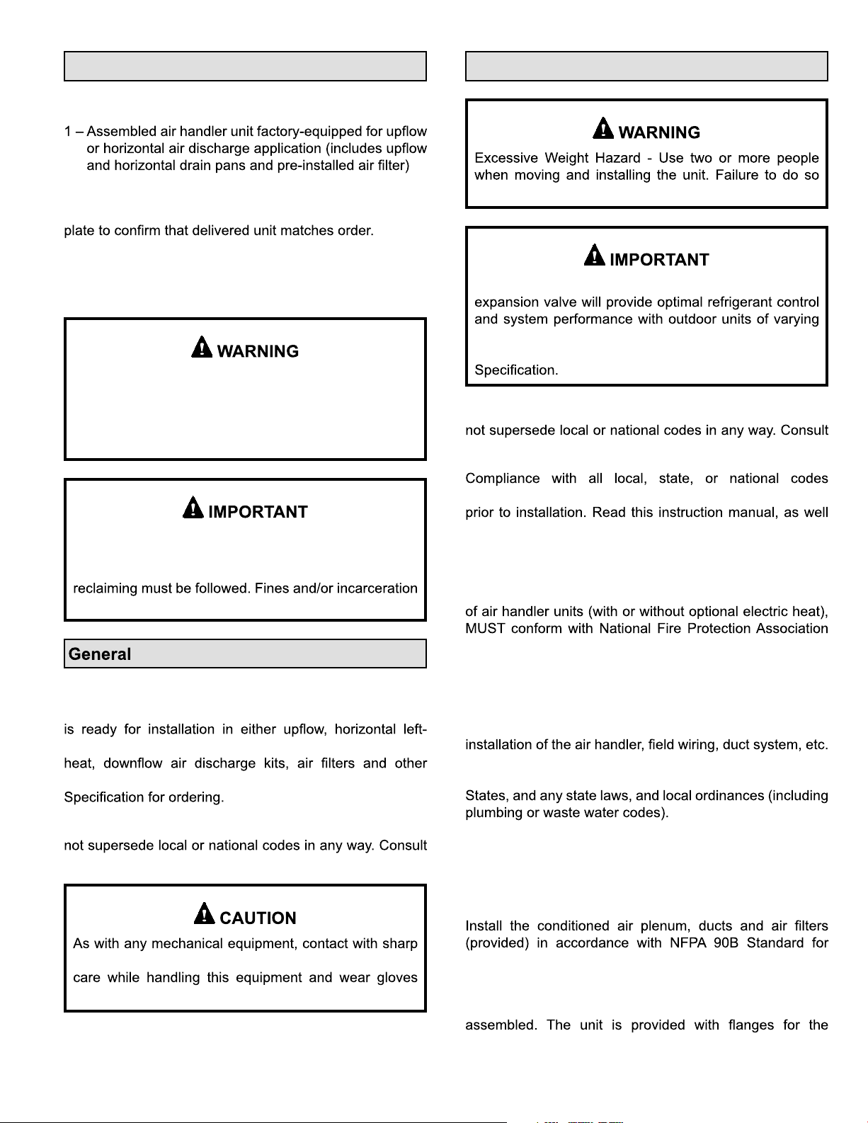
Package 1 of 1 contains:
Requirements
Check the air handler for shipping damage; if found,
immediately contact the last carrier. Check the unit rating
NOTE: Special procedures are required for cleaning
the all-aluminum coil in this unit. See Page 20 in this
instruction for information.
Improper installation, adjustment, alteration, service
or maintenance can cause property damage, personal
injury or loss of life. Installation and service must be
performed by a licensed professional HVAC installer or
equivalent, service agency, or the gas supplier.
The Clean Air Act of 1990 bans the intentional venting
of refrigerant (CFCs, HCFCs and HFCs) as of July
1, 1992. Approved methods of recovery, recycling or
may be levied for noncompliance.
can result in back or other type of injury.
MAHM*CTA units include a factory-installed check/
capacities. These units must be installed as a part of
a matched system as outlined in the MAHM*CTA Product
These instructions are intended as a general guide and do
authorities having jurisdiction before installation.
pertaining to this type of equipment should be determined
as the instructions supplied in separate equipment, before
starting the installation.
In addition to conforming to manufacturer’s installation
instructions and local municipal building codes, installation
The
MAHM*CTA series air handler with all-aluminum coil is
designed for indoor installation only. As shipped, the unit
hand or right-hand air discharge applications. Electric
accessories are available and listed in the Product
This instruction is intended as a general guide and does
authorities having jurisdiction before installation.
sheet metal edges can result in personal injury. Take
and protective clothing.
(NFPA) standards: “Standard for Installation of Air
Conditioning and Ventilation Systems” (NFPA No. 90A)
and “Standard for Installation of Residence Type Warm Air
Heating and Air Conditioning Systems” (NFPA No. 90B).
All models are designed for indoor installation only. The
must conform to the requirements of the National Electrical
Code, ANSI/NFPA No. 70 (latest edition) in the United
Local authorities having jurisdiction should be consulted
before installation is made. Such applicable regulations
or requirements take precedence over the general
instructions in this manual.
the Installation of Warm Air Heating and Air-Conditioning
Systems (latest edition).
The air handler is shipped from the factory completely
connection of the duct system.
507787-01C mrcool.com Page 3 of 22
Page 5
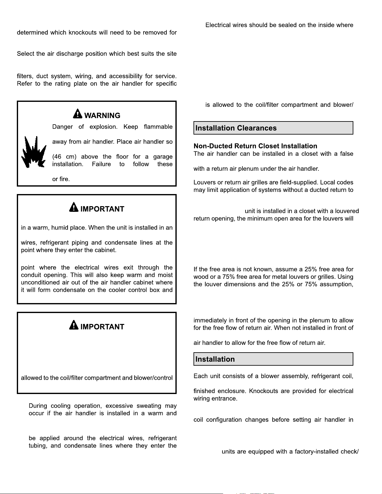
Do not remove the cabinet knockouts until it has been
the installation.
conditions. Consider required clearances, space, routing
requirements for refrigerant line, condensate disposal,
information.
materials and vapors, such as gasoline,
that heating elements are at least 18 inches
instructions can result in death, explosion,
•
they exit the conduit opening. Sealant is required to
prevent air leakage into, and condensate from forming
inside of, the air handler, the control box, and on the
electrical controls.
• This unit is approved for installation clearance to
combustible material as stated on the unit rating
plate. Accessibility and service clearances must take
precedence over combustible material clearances.
• The air handler must be installed so that free access
control compartment.
bottom to form a return air plenum. It may also be installed
single-story buildings.
Excessive condensation may occur if the unit is installed
unconditioned space, apply sealant around electrical
Apply sealant on the inside of the cabinet at the
electrical controls.
This unit is approved for installation clearance to
combustible material as stated on the unit rating
plate. Accessibility and service clearances must take
precedence over combustible material clearances.
The air handler must be installed so that free access is
compartment.
When a MAHM*CTA
be:
• 320 square inches for -018 and -024 models;
• 360 square inches for -030 and -036 models;
• 450 square inches for -042 thru -060 models
determine if the open area meets the minimum open area
listed above.
If a return air plenum is used, the return air grille should be
the opening, there must be adequate clearance around the
and controls in an insulated galvanized steel factory-
•
humid space.
• If installed in an unconditioned space, sealant should
cabinet.
For ease in installation, it is best to make any necessary
place.
Refrigerant Metering Device
MAHM*CTA
expansion valve or an RFC device.
507787-01Cmrcool.comPage 4 of 22
Page 6
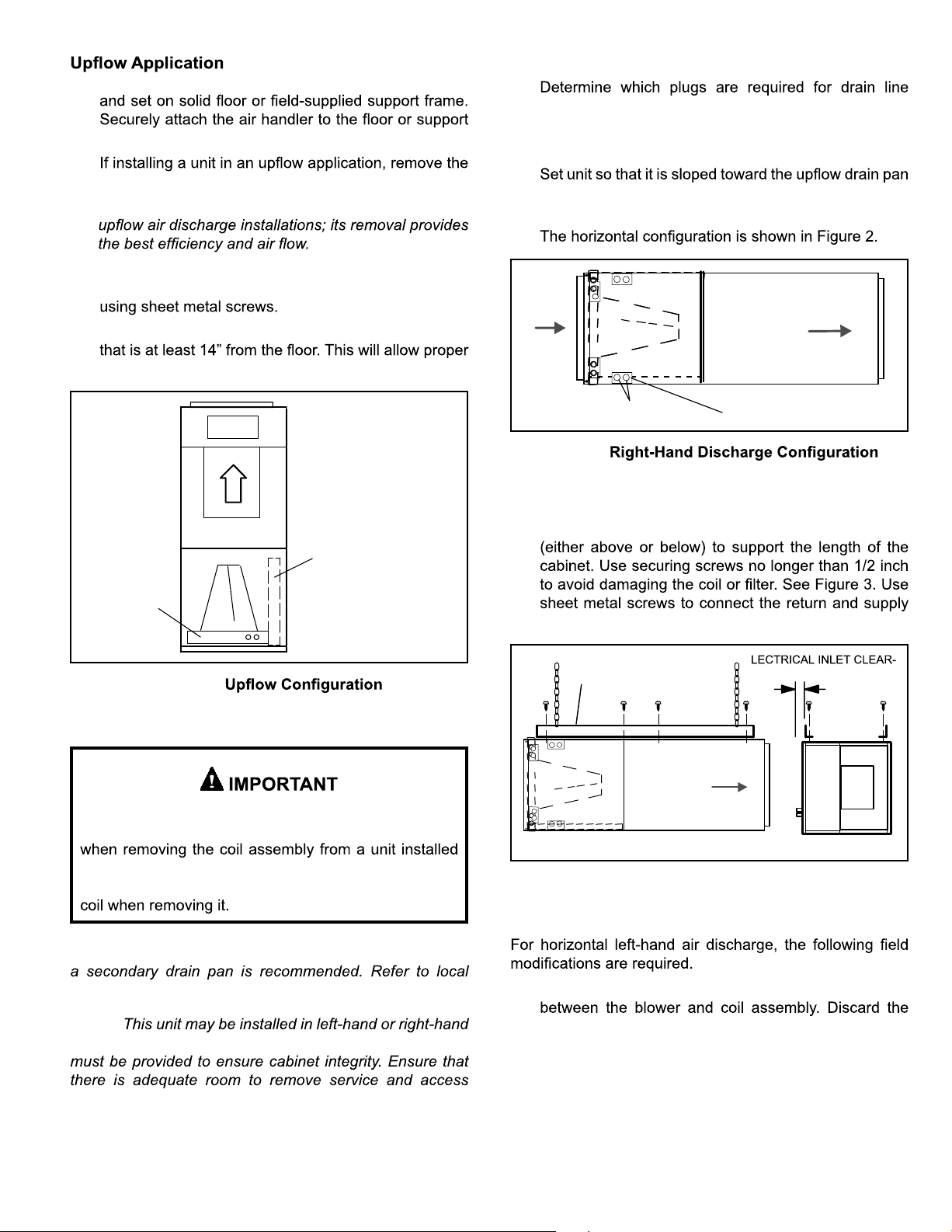
1. The air handler must be supported on the bottom only
frame.
2.
horizontal drain pan.
NOTE: The horizontal drain pan is not required in
3. Place the unit in the desired location and slope unit.
Connect return and supply air plenums as required
Right-Hand Discharge
1.
connections.
2. With access door removed, remove drain line plugs to
install drain lines.
3.
end of the unit and level from front to back of unit (see
Figure 6).
4.
4. Install units that have no return air plenum on a stand
air return.
HORIZONTAL DRAIN PAN
(MUST BE REMOVED)
UP-FLOW /
DOWN-FLOW
DRAIN PAN
Figure 1.
Horizontal Applications
AIR FLOW
Drains
RIGHT‐HAND DRAINS
PLUGS
Figure 2.
5. If the unit is suspended, the entire length of the cabinet
must be supported. If you use a chain or strap, use a
piece of angle iron or sheet metal attached to the unit
air plenums as required.
ANGLE IRON OR SHEET
METAL
MAXIMUM 1/2"
LONG SCREW
E
ANCE 4 IN. (102 MM)
AIR FLOW
When removing the coil, there is a possibility of danger
of equipment damage and personal injury. Be careful
FRONT WEIVDNEWEIV
in right- or left-hand applications. The coil may tip into
the drain pan once it is clear of the cabinet. Support the
Figure 3. Suspending Horizontal Unit
Left-Hand Air Discharge
NOTE: When the unit is installed in horizontal applications,
codes.
NOTE:
air discharge horizontal applications. Adequate support
1. Remove access panels and the corrugated padding
corrugated padding.
2. Pull the coil assembly from unit. Pull off the horizontal
drain pan.
panels if installing in the horizontal position.
3. Remove the drain plugs from back drain holes on
horizontal drain pan and reinstall them on front holes.
507787-01C mrcool.com Page 5 of 22
Page 7

NOTE:
into the coil end plate engaging holes. Misaligned
After removal of drain pan plug(s), check drain hole(s)
to verify that drain opening is fully open and free of any
debris. Also check to make sure that no debris has
fallen into the drain pan during installation that may plug
up the drain opening.
4. Rotate drain pan 180º front-to-back and install it on the
opposite side of the coil.
5.
6. Remove plastic plug from left hole on coil front end
seal and reinstall plug in back hole.
TOP CAP ROTATED TO
CORRECT POSITION
CABINET
SUPPORT
DRAIN PAN
REINSTALLED
HERE
90º
BEND
TOP CAP SCREWS
DRAIN PAN
SHIPPING
LOCATION
8.
support rail as illustrated.
9. Install the horizontal shield (-060 model) on the front
edge of the horizontal drain pan as illustrated in Figure
5.
NOTE:
of humid air.
10. Knock out drain seal plate from access door. Secure
11. Flip access door and replace it on the unit.
12.
end of the unit. Connect return and supply air plenums
13. If suspending the unit, it must be supported along the
entire length of the cabinet. If using chain or strap,
use a piece of angle iron or sheet metal attached to
REINSTALLED HERE REMOVED FROM HERE
COIL SHOWN IN UPLOAD POSITION FOR EASY CONVERSION
TOP
CAP
90º
BEND
———— DRAIN PLUGS ————
ALIGN HOLES WITH
HOLES IN COIL END
PLATE. STARTING WITH
THE ROUND HOLES ON
THIS END.
BACK COIL END SEAL
Figure 4.
7.
back coil end plates. The top cap has a 45º bend on
one side and a 90º bend on the other. The 90º bend
must be on the same side as the horizontal drain
pan as illustrated in Figure 4.
illustrated in Figure 3. Connect return and supply air
NOTE:
kit.
If electric heat section with circuit breakers (ECBA25) is
installed in a MAHM*CTA unit in a downflow application, the
circuit breakers must be rotated 180° to the UP position.
See ECBA25 installation instructions for more details.
DOWN-FLOW RAIL FRONT EDGE OF HORIZONTAL
Figure 5.
DRAIN PAN
507787-01Cmrcool.comPage 6 of 22
Page 8
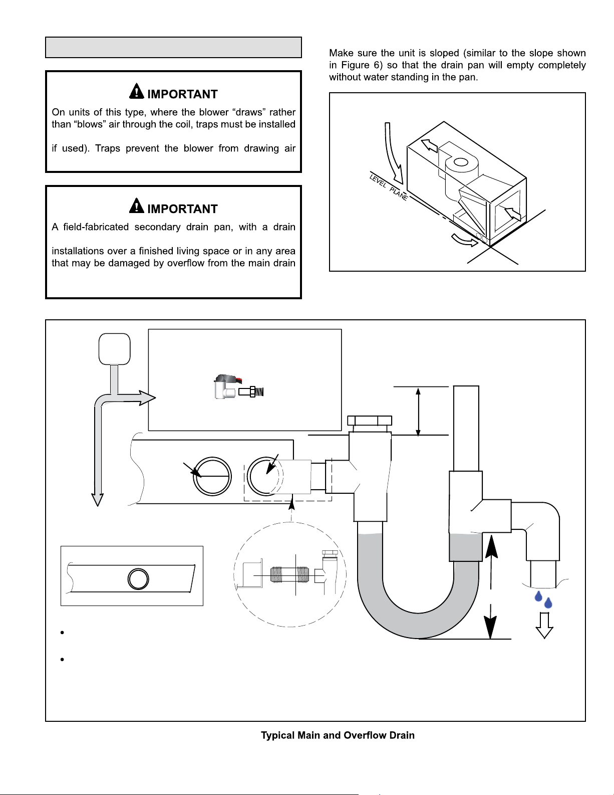
Condensate Drain
in the condensate drain lines (primary and auxiliary,
through the drain lines into the air supply.
Sloping The Unit
THIS CORNER SHOULD BE 5/8" (+/- 1/8") HIGHER
THAN DRAIN CORNER
pipe to the outside of the building, is required in all
DRAIN CORNER
pan. In some localities, local codes may require a
secondary drain pan for any horizontal installation.
ABOVE
FINISHED
SPACE?
YES
NOTE — WHEN A AIR HANDLER IS LOCATED
ABOVE A FINISHED SPACE THE SECONDARY
DRAIN PAN MUST HAVE A LARGER FOOTPRINT
THAN THE AIR HANDLER.
SECONDARY
DRAIN PAN
WHEN A COIL IS LOCATED ABOVE A FINISHED SPACE, A
3/4” (19.1MM) SECONDARY DRAIN LINE MUST BE:
CONNECTED TO SECONDARY DRAIN PAN
OR
CONNECTED TO THE OVERFLOW DRAIN OUTLET OF
THE AIR HANDLER DRAIN PAN.
TRAPS MUST BE DEEP ENOUGH TO OFFSET MAXIMUM STATIC DIFFERENCES —
GENERALLY, TWO INCHES (51MM).
1
P-TRAP 49P66 REQUIRES A LARGER INSTALLATION SPACE THAN THE J-TRAP 91P90.
2
PIPE NIPPLE PROVIDED IN BAG ASSEMBLY - SCH 80, 3/4” I. D. X 5” - 34K7401 (1): CUT THE PIPE IN HALF AND USE IT TO ROUTE THE MAIN DRAIN.
ALWAYS RUN AN OVERFLOW DRAIN LINE. IF NOT POSSIBLE TO
ROUTE OVERFLOW DRAIN LINE, INSTALL LOW VOLTAGE
OVERFLOW SWITCH KIT. WIRE KIT TO SHUT DOWN
COMPRESSOR PER INSTRUCTIONS.
COMPACT OVERFLOW SWITCH WITH 3/4” FEMALE SLIP INLET
NO
AND MALE ADAPTER, TWO PART DESIGN FOR USE WHERE
OBSTRUCTIONS PREVENT DIRECT THREADING
AIR HANDLER DRAIN PAN
OVERFLOW
DRAIN
OVERFLOW DRAIN LINE
PART #
X3169
MAIN
DRAIN
MAIN
DRAIN
CUT TO
REQUIRED
LENGTH
PROVIDED
PIPE NIPPLE
SIDE VIEW
2
Figure 6. Sloping the Unit for Proper Drainage
VENT MUST EXTEND
ABOVE HEIGHT OF
COIL DRAIN PAN BY
TWO INCHES (51MM)
CLEAN OUT
PRESS IN
(DO NOT GLUE)
1” X 3/4” X 3/4”
REDUCING
TEE WITH
PLUG
1
P-TRAP
49P66, J-TRAP #
91P90 OR ANY
PVC SCH 40 P- OR
J-TRAP 3/4”
FOR NEGATIVE PRESSURE COILS (BLOWER
AFTER COIL) TRAPS ARE REQUIRED ON ALL
DRAIN LINES CONNECTED TO COIL.
VENT
TRAP DEPTH
LEVEL PLANE
2”
(51MM)
DRAIN LINE SHOULD
SLOPE A MINIMUM OF
ONE INCH PER 10
FEET (25MM PER 3
METERS)
TO APPROVED
DRAIN
Figure 7.
507787-01C mrcool.com Page 7 of 22
Page 9

connections.
On some pans, the primary and secondary drain holes
have knockouts.
1. MAHM*CTA
includes green (main drain) and red (secondary drain)
UNSCREW PLUGS
AND CONNECT
PROPERLY SIZED
FIELD-PROVIDED
FITTINGS AND
DRAIN LINES.
DRAIN PAN
GREEN MAIN
DRAIN PLUG
RED SECONDARY
DRAIN PLUG
Figure 8. Drain Line Connections
NOTE:
7. Route the drain line to the outside or to an appropriate
drain. Drain lines must be installed so they do not block
service access to the front of the air handler. A 24”
and service access.
NOTE:
Test Condensate Drain
Test the drain pan and drain line after installation:
1.
2. Check the installed drain pan. Drain pan must be
leaking. Water must be draining from the end of the
primary drain line.
3. Correct any leaks found.
2.
and connect primary drain line to the main drain pan
connection.
NOTE:
connections on the drain pan.
3. If the secondary drain line is to be used, remove the
plug or the knockout and route the drain line so that
requirements on the secondary drain line.
4. Check again to ensure drain ports and drain pan are
free of all debris.
5. Plug and check any unused drain pan openings for
leaks or seepage from the drain pan.
6. Install a 2” trap in the main (primary) drain lines as
close to the unit as practical (see Figure 7). Make sure
NOTE:
Duct System and Filters
Duct System
of the supply plenum.
Supply and return duct system must be adequately sized
to meet the system’s air requirements and static pressure
conditioned areas or 2” minimum in unconditioned areas.
extend at least 3 ft. from the air handler before turning or
branching off plenum into duct runs. The plenum forms
Filters
Model Filter Size – in.
-018, -024, -030 15" x 20" x 1"
-036, -042, -048, -060 18" x 20" x 1"
Table 1. Unit Air Filter Size Chart
507787-01Cmrcool.comPage 8 of 22
Page 10

Brazing Refrigerant Lines
and performance may be reduced. The pressure drop
may also cause the limit to trip more frequently during
resulting in an increase in the number of service
against the data given in the appropriate Product
Service and Application Note ACC002 (August 2000).
handler. If an isolation connector is used, it must be
Field-Fabricated Return Air Duct Flange for
Horizontal Applications
A return air duct system is recommended, but not factory-
closet, run a full-size return connection to a location outside
the closet.
Cabinet and Duct Flange
CABINET
DOOR FLANGE
1−1/2
(38)
DUCT
FLANGE
3/4
(19)
1−1/2(38)
3/4
(19)
”A”
BRAKE DOWN 90 DEGREES
1/2
(13)
UNIT SIZE
-018, -024,
-030
-036, -042,
-048, -060
3/4
(19)
1/4 (6) DIA.
2−HOLES
"A"
18-3/8"
21-1/2"
BOTTOM OF
CABINET
DUCT
ADAPTER
3/4
(19)
1−1/2
(38)
Refrigerant lines must be clean, dry, refrigerant-grade
copper lines. Air handler coils should be installed
combinations.
Handle the refrigerant lines gently during the installation
restriction.
Do not remove the caps from the lines or system
connection points until connections are ready to be
completed.
absorb moisture very quickly. It is very important that the
refrigerant system be kept closed as much as possible.
DO NOT remove line set caps or service valve stub
caps until you are ready to make connections.
charge from only the high side may result in
suction tubing. Application of a brazing torch
to a pressurized system may result in
ignition of the refrigerant and oil mixture.
applying heat.
When using a high pressure gas such as
nitrogen to pressurize a refrigeration or air
conditioning system, use a regulator that
(6.9 to 13.8 kPa).
Figure 9. Cabinet and Duct Flange
507787-01C mrcool.com Page 9 of 22
Page 11

hazardous to your health.
Avoid breathing vapors or fumes from brazing
areas.
Wear gloves and protective goggles or face shield to
protect against burns.
prevent oxidation and the introduction of moisture into
the system.
NOTE:
.
1.
the lines in a direct path, avoiding unnecessary turns
and bends.
2. Make sure that the suction line is insulated over the
entire exposed length and that neither suction nor
3. To avoid damaging the rubber grommets in the cabinet
source.
NOTE:
suction line connections.
4. Connect the suction and liquid lines to the evaporator
coil. Take care to protect the cabinet and internal
components as detailed in Figure 10.
5. Braze using an alloy of silver or copper and phosphorus
NOTE: Do not use soft solder.
6.
NOTE:
7. Reinstall the rubber grommets into the refrigerant
piping panel.
NOTE:
not touching metal edges or copper tubing.
8. Make sure outdoor unit has been placed according
to the Installation Instructions and is connected to the
refrigerant lines
507787-01Cmrcool.comPage 10 of 22
Page 12

PLEASE READ IMPORTANT ISSUES CONCERNING BRAZING
p
OPERATIONS IN THE BRAZING REFRIGERANT LINES SECTION
BEFORE PROCEEDING.
NOTE - REFER TO OUTDOOR UNIT INSTALLATION
INSTRUCTIONS FOR REFRIGERANT PIPING SIZE
REQUIREMENTS.
NOTE - Use silver alloy brazing rods with five or six percent
minimum silver alloy for copper-to-copper brazing, 45
ercent alloy for copper-to-brass and copper-to-steel
brazing.
REMOVE ACCESS PANEL
A
REMOVE RUBBER PLUG FROM BOTH LIQUID
B
AND SUCTION LINES
NOTE - MAHM*CTA SERI ES UNITS USE NITROGEN OR DRY AIR
AS A HOLDIN G CHARGE. IF THERE IS NO PRESSURE WHEN
THE RUBBER PLUGS ARE REMOVED, CHECK THE COI L FOR
LEAKS BEFOR E INSTALLING.
EITHER REMOVE OR PUSH PIPE WRAPPING BACK
C
THROUGH HOLE IN PIPING PLATE BEFORE LINE
SET CONNECTION AND BRAZING.
LOW
HIGH
PIPING
PLATE
CONNECT PIPES
D
NOTE - REFRIGERANT LINE SETS
SHOULD BE ROUTED TO ALLOW
FILTER ACCESSIBILITY.
PLACE A WET RAG AGAINST PIPING
F
PLATE AND AROUND THE SUCTION
LINE CONNECTION.
BRAZE CONNECTION. ALLOW PIPE TO
G
COOL BEFORE REMOVING WET RAG
FROM CTXV SENSING BULB AND PIPING
PANEL AREA.
REPEAT PREVIOUS PROCEDURE FOR LIQUID
H
LINE.
CONNECT GAUGES AND
E
START NITROGEN FLOW
FLOW REGULATED NITROGEN (
THROUGH THE REFRIGERATION GAUGE SET INTO THE
VALVE STEM PORT CONNECTION ON THE OUTDOOR
UNIT LIQUID LINE SERVICE VALVE AND OUT OF THE
VALVE STEM PORT CONNECTION ON THE SUCTION
SERVICE VALVE.
REFER TO INSTRUCTIONS PROVIDED WITH OUTDOOR
UNIT FOR LEAK TESTING, EVACUATING AND CHARGING
PROCEDURES
AT 1 TO 2 PSIG)
NITROGEN
Figure 10. Brazing Connections
507787-01C mrcool.com Page 11 of 22
Page 13

Sealing the Unit
installed in an unconditioned area.
Electric Shock Hazard. Can cause injury or
death. Unit must be properly grounded in
If installed in an unconditioned space, sealant should be
sealing strips, caulking, or equivalent sealing method
Use duct tape and/ or Permagum to seal closed any
any gaps or holes in the cabinet.
pole contactors. Disconnect all remote electric
Electric Shock Hazard.
Can cause injury or death.
Foil-faced insulation has conductive
characteristics similar to metal. Be sure there
insulation. If the foil-faced insulation comes in
provide a path for current to pass through
to the outer metal cabinet. While the current
produced may not be enough to trip existing
electrical safety devices (e.g., fuses or circuit
breakers), the current can be enough to cause
an electrical shock hazard that could cause
personal injury or death.
Electrical Connections
supplies before servicing.
Replace all parts and panels before operating.
Failure to do so can result in death or electrical
shock.
in one opening.
• Wiring must conform to the current National Electric
Code ANSI/NFPA No. 70, or Canadian Electric Code
Part I, CSA Standard C22.1, and local building codes.
for minimum circuit ampacity and maximum overcurrent protection size.
•
protection are to be supplied by the installer. Refer
to the air handler rating plate for maximum over-
as operating voltage. Select the proper supply circuit
17 in the National Electric Code, ANSI/NFPA No. 70 or
tables 1 through 4 in the Canadian Electric Code, Part
I, CSA Standard C22.1.
•
•
single phase, 60 cycles. For 208-volt applications, see
“208 Volt Conversion” later in this section.
507787-01Cmrcool.comPage 12 of 22
Page 14

•
voltage and line voltage. Refer to the dimension
•
provided caps to seal holes not used.
•
installed electric heat) is given in Figure 14. Refer to
for proper installation.
USE COPPER CONDUCTORS ONLY
1.
2. Remove the air handler access panel.
3.
connection box.
4.
5. Replace the air handler access panel.
TOP
SIDE
Figure 12. Control Panel Relocated to End Panel
208 Volt Conversion
1.
2. Remove the air handler access panel.
3.
panel as a reference, move the 2 connected black
transformer leads from the 240 volt terminal on the
transformer to the 208 volt terminal on the transformer.
NOTE:
in Figure 12.
SIDE
Figure 11. Electrical Connections
TOP
Electrically ground air handler. Connect
Failure to do so can result in death or electrical
shock.
208 / 240 VOLT TRANSFORMER
PRIMARY SECONDARY
240 Volts
208 Volts
Figure 13. Converting Unit from 240VAC to 208VAC
507787-01C mrcool.com Page 13 of 22
Page 15

Figure 14. Typical Wiring Diagram
MAHM*CTA
507787-01Cmrcool.comPage 14 of 22
Page 16

Figure 15. Typical Wiring Diagram MAHM*CTA
507787-01C mrcool.com Page 15 of 22
Page 17

SEE
NOTE
AIR HANDLERTHERMOSTAT
R
G
BU
Y
AIR
CONDITIONER
UNIT
COOLING‐ONLY APPLICATION
NOTE
THERMOSTAT
SEE
AIR HANDLERTHERMOSTAT
R
G
BU
W
HEAT‐ONLY APPLICATION
AIR HANDLER
R
HEAT PUMP
UNIT
AIR HANDLERTHERMOSTAT
R
G
W
BK
SEE
NOTE
COOLING APPLICATION WITH
BU
Y
AIR CONDITIONER
ELECTRIC HEAT
UNIT
NOTE - Connect common wire only if required (Refer to the appropriate thermostat installation instructions).
Figure 16.
Air Flow – Cooling Blower Speed
CONNECT COMMON
WIRE ONLY IF
REQUIRED
(REFER TO THE
APPROPRIATE
THERMOSTAT
INSTALLATION
INSTRUCTIONS)
G
BU
BK
W
HEAT PUMP APPLICATION WITH
ELECTRIC HEAT
capacity rating of the air handler.
If the outdoor unit is smaller than the maximum cooling
chart in Table 2.
supplies before servicing.
Replace all parts and panels before operating.
Failure to do so can result in death or electrical
shock.
Change Blower Speed
1.
2. Remove the air handler access panel.
3.
4.
harness connector.
NOTE:
5. Replace all panels.
6.
507787-01Cmrcool.comPage 16 of 22
Page 18

BLOWER RELAY
NOTE - Refer to wiring diagram located on the
unit
ance (table 2).
All air data measured external to unit with 1
inch non-pleated air filter in place.
All factory settings are medium speed.
5
BLOWER RELAY
HARNESS
BLUE (MED)
2
PLASTIC CAPS
RED (L0)
BLACK (HI)
All data given while air handler is operating
with a dry DX coil.
All downflow applications run on high speed
YELLOW (COM)
when utilizing electric heat.
4-PIN
BLOWER CONNECTOR
Figure 17. Changing Blower Speed
NOTE:
Air Handler Model Blower Speed .10" WC .20" WC .30" WC .40" WC .50" WC
LOW 538 525 503 471 418
-018
-024
-030
-036
-042
-048
-060
MED 688 670 639 603 548
HIGH 919 881 855 788 710
LOW 677 673 657 629 592
MED 1011 979 942 803 742
HIGH 1106 1045 999 917 857
LOW 871 870 853 812 769
MED 1078 1057 1024 987 936
HIGH 1311 1261 1214 1154 1086
LOW 1020 972 956 909 806
MED 1276 1240 1191 1148 1086
HIGH 1559 1521 1446 1395 1327
LOW 1300 1273 1250 1211 1155
MED 1527 1493 1452 1390 1345
HIGH 1816 1756 1693 1605 1528
LOW 1257 1212 1157 1116 1053
MED LOW 1486 1448 1411 1364 1330
MED 1721 1675 1630 1594 1553
MED HIGH 1721 1675 1630 1594 1553
HIGH 1840 1794 1754 1721 1681
LOW 1098 1049 1001 926 831
MED LOW 1624 1594 1565 1520 1492
MED 1815 1783 1758 1730 1685
MED HIGH 1903 1869 1837 1809 1764
HIGH 1981 1957 1923 1893 1861
•
•
•
Table 2. MAHM*CTA
507787-01C mrcool.com Page 17 of 22
Page 19

Check-Out Procedures
3 4
NOTE:
instructions.
Pre-Start-Up Checks
• Is the air handler properly and securely installed?
•
1. Set thermostat to call for auxiliary heat (approximately
minimum of 3 minutes for all sequencers to cycle on.
2. Set the thermostat so that it does not call for heat.
Operation
• Will the unit be accessible for servicing?
• Has an auxiliary pan been provided under the unit
could cause damage?
• Have ALL unused drain pan ports been properly
plugged?
• Has the condensate line been properly sized, run,
trapped, pitched, and tested?
• Is the duct system correctly sized, run, sealed, and
insulated?
•
• Is the indoor coil factory-installed TXV or RFC properly
sized for the outdoor unit being used?
• Have all unused parts and packaging been disposed
of?
•
•
• Is the unit properly grounded and protected (fused)?
•
location?
• Are all access panels in place and secure?
Check Blower Operation
1.
come on.
Time Delay Relay
1. When cooling demand is initiated, there is a 1 second
motor-on delay.
2. After the motor-on delay expires, motor ramps up
3.
seconds.
4.
100%
1
1
SECOND
DELAY
2
CFM
COOLING
DEMAND
Figure 18. Blower Time Delay
When the thermostat calls for cooling, 24 volts is put on
relay energizes. The normally open contacts close, causing
and Y is completed, closing the circuit to the contactor in
the outdoor unit, starting the compressor and outdoor fan
motor.
On heat pumps, circuit R and O energizes the reversing
100%
CFM
45
SECS
OFF
Check Cooling Operation
1. Set thermostat to force a call for cooling (approximately
2. The outdoor unit should come on immediately and the
later.
3.
system is moving cooled air.
4. Set the thermostat 5ºF higher than the indoor
should cycle off.
reversing valve remains energized as long as the
and outdoor unit should cycle off. Air handler should cycle
off 45 seconds after the outdoor unit shuts off.
and W is completed, and the heat sequencer is energized.
on the thermostat sub-base, or they may also be connected
to a second stage on the sub-base.
507787-01Cmrcool.comPage 18 of 22
Page 20

When the thermostat calls for heating, 24 volts is applied
the circuit to the contactor in the outdoor unit, starting the
compressor and outdoor fan motor.
If the room temperature continues to decrease, the circuit
room thermostat. Circuit R-W1 energizes a heat sequencer.
REPLACED before the unit is put back into operation.
separated or torn.
Matte- or foil-faced insulation is installed in indoor
thermostat. They may also be connected to a second
heating stage W2 on the thermostat sub-base.
on the thermostat sub-base so that the electric heat control
Homeowner Maintenance
duct by the installer.
conditions (surrounding ambient temperature and humidity)
and the varying conditions inside the unit. If the insulation
inside surface temperature of the cabinet.
and outside of the cabinet can cause condensation on the
corrosion and, subsequently, component failure.
Areas of condensation on the cabinet surface are an
indication that the insulation is in need of repair.
condition, the insulation should be cut in an X pattern,
and placed back against the cabinet surface, being careful
to not overly compress the insulation so the insulation can
retain its original thickness. If such repair is not possible,
replace the insulation. If using foil-faced insulation, any
cut, tear, or separations in the insulation surface must be
•
cause of inadequate heating or cooling performance.
•
GLUE - Make sure there is
full coverage of glue on the
•
sized for it.
•
1. CUT INSULATION IN X PATTERN
2. APPLY GLUE
3. PRESS GLUED TABS AGAINST CABINET
metal or insulation so there
are no areas where air
pockets may form which
can lead to sweating.
Figure 19.
507787-01C mrcool.com Page 19 of 22
Page 21

Professional Maintenance
unit.
(less than 50psi). If the coil cannot be cleaned using
thoroughly after cleaning.
(salt).
Use of Air Handler During Construction
It is not recommended to use this air handler unit during any
Air handler units may be used for heating (heat pumps)
conditions are met:
• A room thermostat must control the air handler. The
•
maintained during construction.
•
completion.
• The air handler evaporator coil, supply fan assembly
•
according to these installation instructions.
507787-01Cmrcool.comPage 20 of 22
Page 22

Installing Contractor’s Name_______________________
_
Installing Contractor’s Phone_______________________
Job Address____________________________________
8
Temperature
1
Duct
System
5
Duct Static
Installing Date_______________________________
Air Handler Model #__________________________
Thermostat
SUPPLY
AIR
9
Disconnect
Switch
2
Line Voltage
3
Integrated Control
Blower Motor Amps
6
Electric Heat Amps
7
RETURN
AIR
DUCT SYSTEM
1
SUPPLY AIR DUCT
Sealed
Insulated (if necessary)
Registers Open and Unobstructed
RETURN AIR DUCT
Sealed
Filter Installed and Clean
Registers Open and Unobstructed
2
INTEGRATED CONTROL
Jumpers Configured Correctly (if applicable)
Appropriate Links in Place (if applicable)
3
VOLTAGE CHECK
Supply Voltage ___________
Low Voltage _____________
Electrial Connections Tight
4
DRAIN LINE
Leak Free
Filter
TOTAL EXTERNAL STATIC (dry coil)
5
Supply External Static ______ ______
Return External Static ______ ______
Total External Static = ______ ______
6
ELECTRIC HEAT AMPS____________
7
INDOOR BLOWER AMPS___________
INDOOR BLOWER CFM____________
TEMPERATURE DROP (Cooling Mode)
8
Return Duct Temperature ___________
Supply Duct Temperature − ___________
8
TEMPERATURE RISE (Heating Mode)
Return Duct Temperature __________
Supply Duct Temperature − __________
9
THERMOSTAT
Adjusted and Programmed
Operation Explained to Owner
4
Drain Line
dry coil wet coil
Temperature Drop = ___________
Temperature Rise = __________
Explained Operation of System to Homeowner
Technician’s Name:_______________________Date Start−Up & Performance Check Completed__________
Figure 20.
507787-01C mrcool.com Page 21 of 22
Page 23

Installing Contractor’s Name_______________________
_
Installing Contractor’s Phone_______________________
Job Address____________________________________
Thermostat
9
1
Duct System
2
Integrated
Control
Filter
RETURN
AIR
4
Drain Line
5
Installing Date_______________________________
Air Handler Model #__________________________
Disconnect
Switch
Line Voltage
3
1
Duct System
SUPPLY
AIR
Electric Heat Amps
6
Blower motor Amps
7
8
DUCT SYSTEM
1
SUPPLY AIR DUCT
Sealed
Insulated (if necessary)
Registers Open and Unobstructed
RETURN AIR DUCT
Sealed
Filter Installed and Clean
Registers Open and Unobstructed
2
INTEGRATED CONTROL
Jumpers Configured Correctly (if applicable)
Appropriate Links in Place (if applicable)
3
VOLTAGE CHECK
Supply Voltage ___________
Low Voltage _____________
Electrial Connections Tight
4
DRAIN LINE
Leak Free
Duct Static
Temperature
TOTAL EXTERNAL STATIC (dry coil)
5
dry coil wet coil
Supply External Static ______ ______
Return External Static ______ ______
Total External Static = ______ ______
6
ELECTRIC HEAT AMPS____________
7
INDOOR BLOWER AMPS___________
INDOOR BLOWER CFM____________
TEMPERATURE DROP (Cooling Mode)
8
Return Duct Temperature ___________
Supply Duct Temperature − ___________
Temperature Drop = ___________
8
TEMPERATURE RISE (Heating Mode)
Return Duct Temperature __________
Supply Duct Temperature − __________
Temperature Rise = __________
9
THERMOSTAT
Adjusted and Programmed
Operation Explained to Owner
Explained Operation of System to Homeowner
Technician’s Name:_______________________Date Start−Up & Performance Check Completed__________
Figure 21.
507787-01Cmrcool.comPage 22 of 22
Page 24

Signature Series
MAHM*CTA Air Handler
ELECTRICIAN and /or HVAC TECHNICIAN:
LICENSE #:
INS TA LLATION DATE:
INSTALLATION LOCATION:
SERIAL NUMBER:
The design and specifications of this product and/or manual are subject to change without prior notice.
Consult with the sales agency or manufacturer for details.
 Loading...