

Page 1
For 13 SEER R410A Unitary
Ducted Split AC & Heat Pump
Installation Manual
Residential Air Conditioners & Heat Pumps
Thank you for choosing Residential Air Conditioners & Heat Pumps, please read this
Installation manual carefully before operation and retain it for future reference.
MRCOOL reserves the right to interpret this manual which will be subject to any change due
to product improvement without further notice.
Page 2

Contents
Safety Considerations ...................................................................................1
1. Unit Parts Arrangement .............................................................................2
2. Physical Dimension ...................................................................................3
2.1 Outdoor Unit
2.2 Installation Clearance Data
2.3 Units Installation
2.4 Installation Recommendations
3. Brazing Connections
3.1 Preparation the Line
3.2 Cap and Core Removal
3.3 Attach Gauge
3.4 Braze Line Set
3.5 Preparation for Next Step
4. Check Piston
..........................................................................................3
...................................................................5
....................................................................................5
.............................................................6
.................................................................................7
.............................................................................7
.........................................................................8
.........................................................................................8
.......................................................................................8
......................................................................9
.............................................................................................9
5. Operating Gauge Set and Service Valves
5.1 Torque Requirements
5.2 Using Manifold Gauge Set
..........................................................................10
..................................................................10
...............................................10
5.3 Operating Service Valves
...................................................................10
5.4 Operating Angle Type Service Valve
5.5 To Access Service Port
5.6 Reinstall Stem Cap
........................................................................11
..............................................................................11
For more details visit www.MrCool.com
...................................................10
Page 3

5.7 Install Liquid Line Filter Drier Indoor ...................................................11
6. Recovering Refrigerant from Existing System
6.1 Disconnect Power
6.2 Connect Manifold Gauge Set
6.3 Recovering Refrigerant
...............................................................................12
..............................................................12
.......................................................................12
.........................................12
6.4 Leak Test Line Set and Indoor Coil......................................................13
6.5 Evacuating Line Set and Indoor Coil
7. Electrical
..................................................................................................15
7.1 Size Circuit And Install Disconnect Switch
7.2 Install Thermostat
................................................................................16
7.3 Unit Low Voltage Connections
7.4 Unit High Voltage Connections
8. System Refrigerant
8.1 Gauge Set (Cooling Only)
8.2 Gauge Set (Heat Pump)
..................................................................................21
...................................................................21
.....................................................................22
...................................................14
..........................................16
............................................................16
............................................................17
8.3 Weigh In
..............................................................................................23
9. Unit Control............................................................................................27
9.1 Mainboard Description
9.2 Terminal Description
9.3 Control Flowchart
9.4 Error Analysis
....................................................................................30
9.5 Setting on Defrost Control PCB (for Heat Pump unit only)
9.6 Manually Defrost Cycle
......................................................................27
..........................................................................28
..............................................................................29
...............33
....................................................................33
For more details visit www.MrCool.com
Page 4
Unitary Ducted Split AC & HP
Safety Considerations
Improper installation, adjustment, alteration, service, maintenance, or use can cause explosion,
fire, electrical shock, or other conditions which may cause death, personal injury, or property
damage. Instructions for installation and use of this product are provided by the manufacturer.
Installation must be performed in accordance with the requirements of NEC and CEC by qualied
installer or agency only. The qualified installer or agency must use factory--authorized kits or
accessories when modifying this product. Refer to the individual instructions packaged with the kits
or accessories when installing. Follow all safety codes. Wear safety glasses, protective clothing,
and work gloves. Use quenching cloth for brazing operations. Have fire extinguisher available.
Read these instructions thoroughly and follow all warnings or cautions included in literature and
attached to the unit. Consult local building codes and National Electrical Code (NEC) for special
requirements. Recognize safety information. This is the safety--alert symbol .When you see this
symbol on the unit and in instructions or manuals, be alert to the potential for personal injury.
Understand these signal words; DANGER, WARNING, and CAUTION. These words are used with
the safety--alert symbol. DANGER identies the most serious hazards which will result in severe
personal injury or death. WARNING signifies hazards which could result in personal injury or
death. CAUTION is used to identify unsafe practices which may result in minor personal injury or
product and property damage. NOTE is used to highlight suggestions which will result in enhanced
installation, reliability, or operation.
WARNING
ELECTRICAL SHOCK HAZARD
Failure to follow this warning could result in personal injury or death.
Before installing, modifying, or servicing system,main electrical disconnect switch must be in
the OFF position. There may be more than 1 disconnect switch. Lock out and tag switch with a
suitable warning label.
This product must not be disposed together with the domestic waste.
This product has to be disposed at an authorized place for recycling of
electrical and electronic appliances.
For more details visit www.MrCool.com
1
Page 5
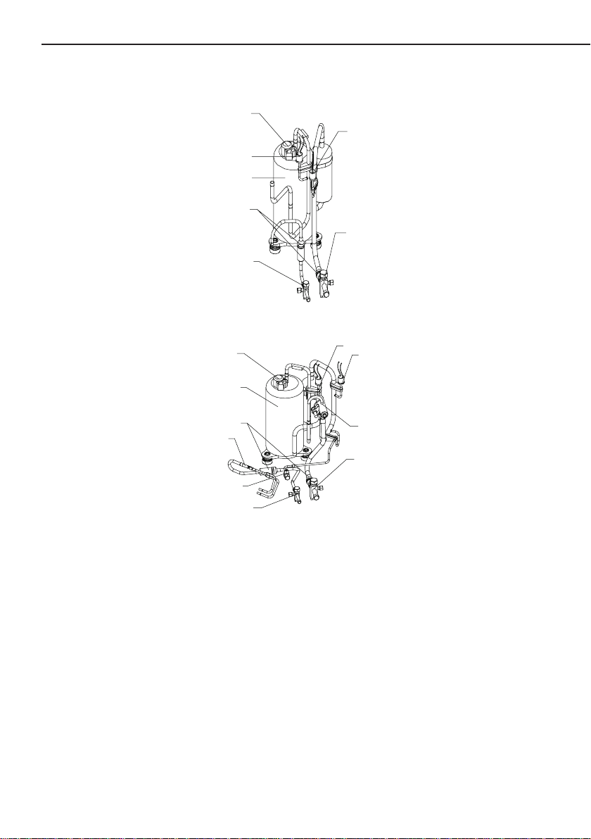
1. Unit Parts Arrangement
Cooling Only Condensing Unit
Compressor harness
High pressure switch
Compressor
Liquid line service valve
Heat Pump Condensing Unit
Compressor harness
Compressor
Unitary Ducted Split AC & HP
Low pressure switch
Filter
Vapor line service valve
Fig.1
High pressure switch
Low pressure switch
Filter
Throttl
e
Nozzle for adding freon
Liquid line service valve
For more details visit www.MrCool.com
Revesing valve
Vapor line service valve
Fig.2
2
Page 6
Unitary Ducted Split AC & HP
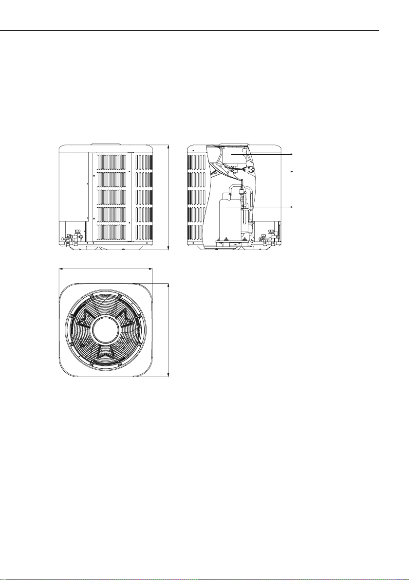
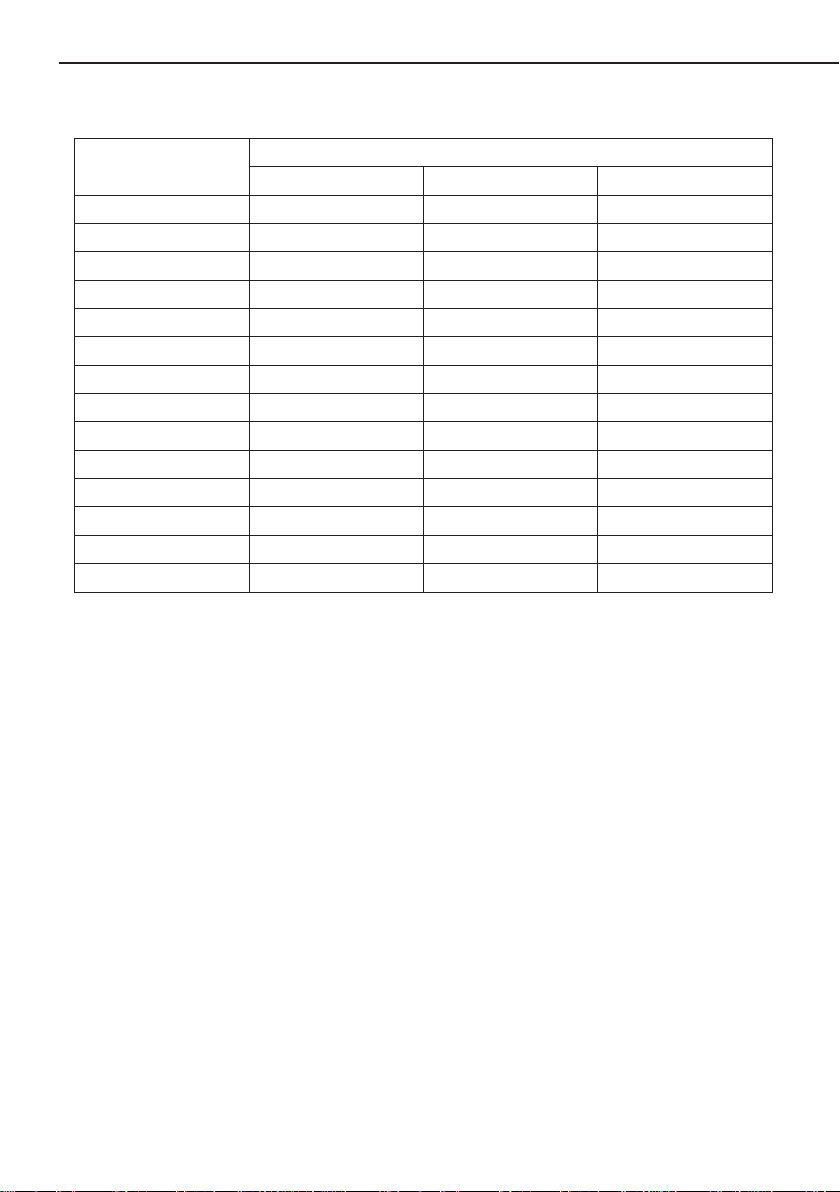
2. Physical Dimension
2.1 Outdoor Unit
W
Fan motor
Axial flow fan
H
Compressor
D
Fig.3—Outdoor Unit
Table 1—Dimension of Outdoor Unit
For more details visit www.MrCool.com
3
Page 7
Unitary Ducted Split AC & HP
Unit: Inch (mm)
MODEL
MAC13018 24"(610) 21-1/2"(546) 21-1/2"(546)
MAC13024 24-1/2"(620) 24"(610) 24"(610)
MAC13030 29"(735) 24"(610) 24"(610)
MAC13036 29"(735) 28"(710) 28"(710)
MAC13042 29"(735) 28"(710) 28"(710)
MAC13048 29"(735) 28"(710) 28"(710)
MAC13060 33-1/2"(850) 29-1/2"(750) 29-1/2"(750)
MHP13018 24-1/2"(620) 24"(610) 24"(610)
MHP13024 24-1/2"(620) 24"(610) 24"(610)
MHP13030 29"(735) 28"(710) 28"(710)
MHP13036 29"(735) 28"(710) 28"(710)
MHP13042 29"(735) 28"(710) 28"(710)
MHP13048 33-1/2"(850) 28"(710) 28"(710)
MHP13060 33-1/2"(850) 29-1/2"(750) 29-1/2"(750)
H D W
DIMENSION
For more details visit www.MrCool.com
4
Page 8
Unitary Ducted Split AC & HP
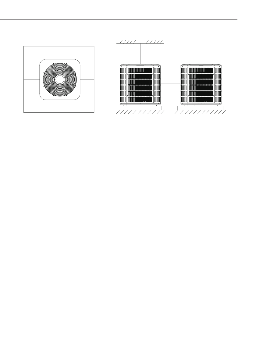
2.2 Installation Clearance Data
Floor
>1000mm
>1000mm
(40inch)
(40inch)
>1000mm
(40inch)
>1000m
(40inch)
m
>3000mm
(120inch)
>800mm
(32inch)
Floor
Fig.4
2.3 Units Installation
2.3.1 Installation Positions of Condensing Units
● Outdoor Unit must be xed on stable and solid surface of oor.
● Don’t install Outdoor Unit under window or between buildings, and prevent the operation
noise from room.
● There should be no obstructions at both air inlet and outlet of indoor and outdoor units for
maintaining well air ventilation.
● When installing indoor unit, make sure that the hanging parts at top are strong enough to
stand the weight of unit.
2.3.2 Matters Need Attention
● Before installation, make sure that the power supply comply with nameplate and check the
security of the power supply.
● Do not use or place combustible and explosive gas or liquid near the air conditioner.
● Do not attempt to install Air Conditioner by yourself to guarantee the air Conditioner can be
permanent use.
● In the event of malfunction(burning smell, etc.),stop operation immediately and turn off the
power switch.
● Do not insert ngers or objects into the outlet port or inlet grillers.
● Do not check or repair the air Conditioner when it is running.
● Do not sprinkle water on the air Conditioner or operate it with wet hands.
● Do not climb or place objects on the air conditioner.
For more details visit www.MrCool.com
5
Page 9
Unitary Ducted Split AC & HP
2.4 Installation Recommendations
NOTE: In some cases noise in the living area has been traced to gas pulsations from improper
installation of equipment.
1). Locate unit away from windows, patios, decks, etc. where unit operation sound may disturb
customer.
2). Ensure that vapor and liquid tube diameters are appropriate for unit capacity.
3). Run refrigerant tubes as directly as possible by avoiding unnecessary turns and bends.
4). Leave some slack between structure and unit to absorb vibration.
5). When passing refrigerant tubes through the wall, seal opening with RTV or other pliable
silicon--based caulk.(See Fig. 5.)
6). Avoid direct tubing contact with water pipes, duct work, oor joists, wall studs, oors, and
walls.
7). Do not suspend refrigerant tubing from joists and studs with a rigid wire or strap which comes
in direct contact with tubing. (See Fig. 5.)
8). Ensure that tubing insulation is pliable and completely surrounds vapor tube.
9). When necessary, use hanger straps which are 1 in. wide and conform to shape of tubing
insulation. (See Fig. 5.)
10). Isolate hanger straps from insulation by using metal sleeves bent to conform to shape of
insulation.
When outdoor unit is connected to factory--approved indoor unit, outdoor unit contains system
refrigerant charge good for 25 ft.
For proper unit operation, check refrigerant charge using charging information located on
control box cover and/or in the Check Charge section of this instruction.
NOTE: Avoid contact between tubing and structure
SUSPENSION
INDOOR WALL
LIQUID TUBE
VAPOR TUBE
JOIST
INSULATION
VAPOR TUBE
LIQUID TUBE
OUTDOOR WALL
CAULK
INSULATION
THROUGH THE WALL
HANGER STRAP
(AROUND VAPOR
TUBE ONLY)
1”MIN.
Fig.5 – Connecting Tubing Installation
For more details visit www.MrCool.com
6
Page 10
Unitary Ducted Split AC & HP
3. Brazing Connections
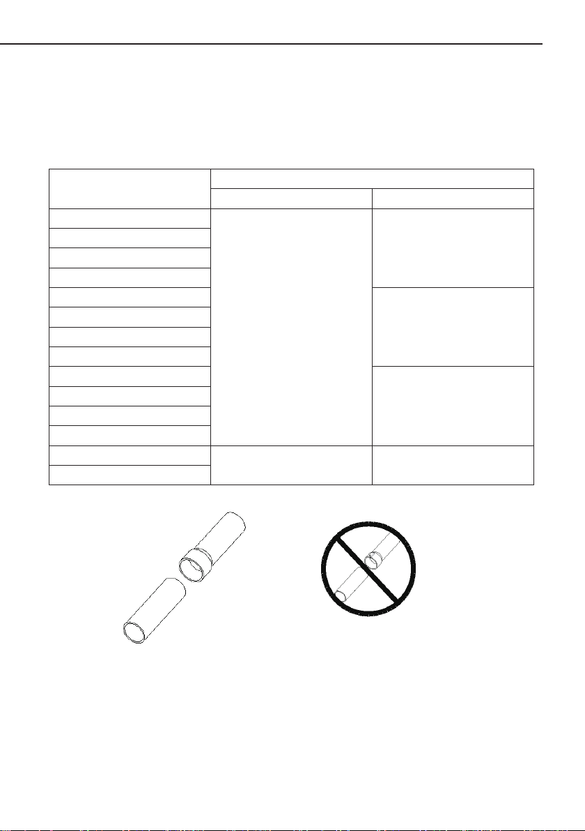
3.1 Preparation the Line
Refer to Table 2 for eld tubing diameters. The pipe must remain round. Do not crimp end of
the line.
Table 2. Refrigerant Line Set Inches (mm)
Model
MAC13018
MHP13018
MAC13024
MHP13024
MAC13030
MHP13030
MAC13036
MHP13036
MAC13042
MHP13042
MAC13048
MHP13048
MAC13060
MHP13060
Liquid Line Vapor Line
3/8 in. (9.5 mm)
1/2 in. (12 mm) 1-1/8 in. (28 mm)
Valve Field Connections
5/8 in. (16 mm)
3/4 in. (19 mm)
7/8 in. (22 mm)
Line set size matches
service valve connection
Do not crimp service valve connector
whenpipe is smaller than connection
Fig.6
For more details visit www.MrCool.com
7
Page 11
Unitary Ducted Split AC & HP
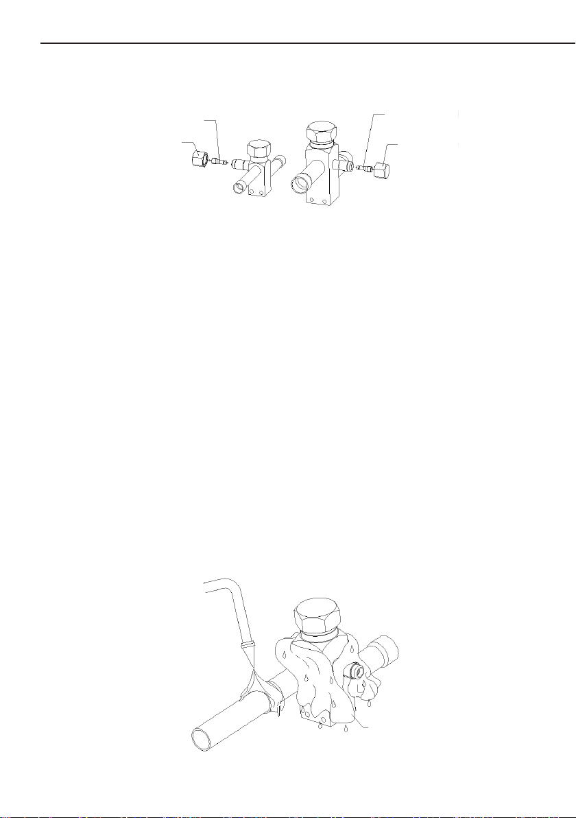
3.2 Cap and Core Removal
Remove service cap and core from both the vapor and liquid line service ports.
Service port core
Service port cap
Service port core
Service port cap
Liquid line
service valve
Vapor line
service valve
Fig.7
3.3 Attach Gauge
Flow regulated nitrogen (at 1 to 2 psig) through the low−side refrigeration gauge set into the
liquid line service port valve, and out of the vapor line service port valve.
Use regulator to flow
nitrogen at 1 to 2 psig
Liquid line
INDOOR
UNIT
Vapor line
Liquid line service valve
OUTDOOR
UNIT
Vapor line service valve
Vapor service port must be open
to allow exit point for nitrogen
Fig.8
3.4 Braze Line Set
To help protect service valve seals during brazing,wrap water saturated cloths around
service valve bodies and copper tube stubs. Water saturated cloths must remain water saturated
throughout the brazing and cool−down process.
Braze line to the service valve.
When brazing line set to
service valves, point flame
away from service valve.
Fig.9
For more details visit www.MrCool.com
8
Water saturated
cloth
Page 12
Unitary Ducted Split AC & HP
3.5 Preparation for Next Step
After all connections have been brazed, disconnect manifold gauge set from service ports.
Apply water saturated cloths to both services valves to cool piping. Once piping is cool, remove all
water saturated cloths.Reinstall service cap and core.Refer to the unit installation instructions for
the next step in preparing the unit.
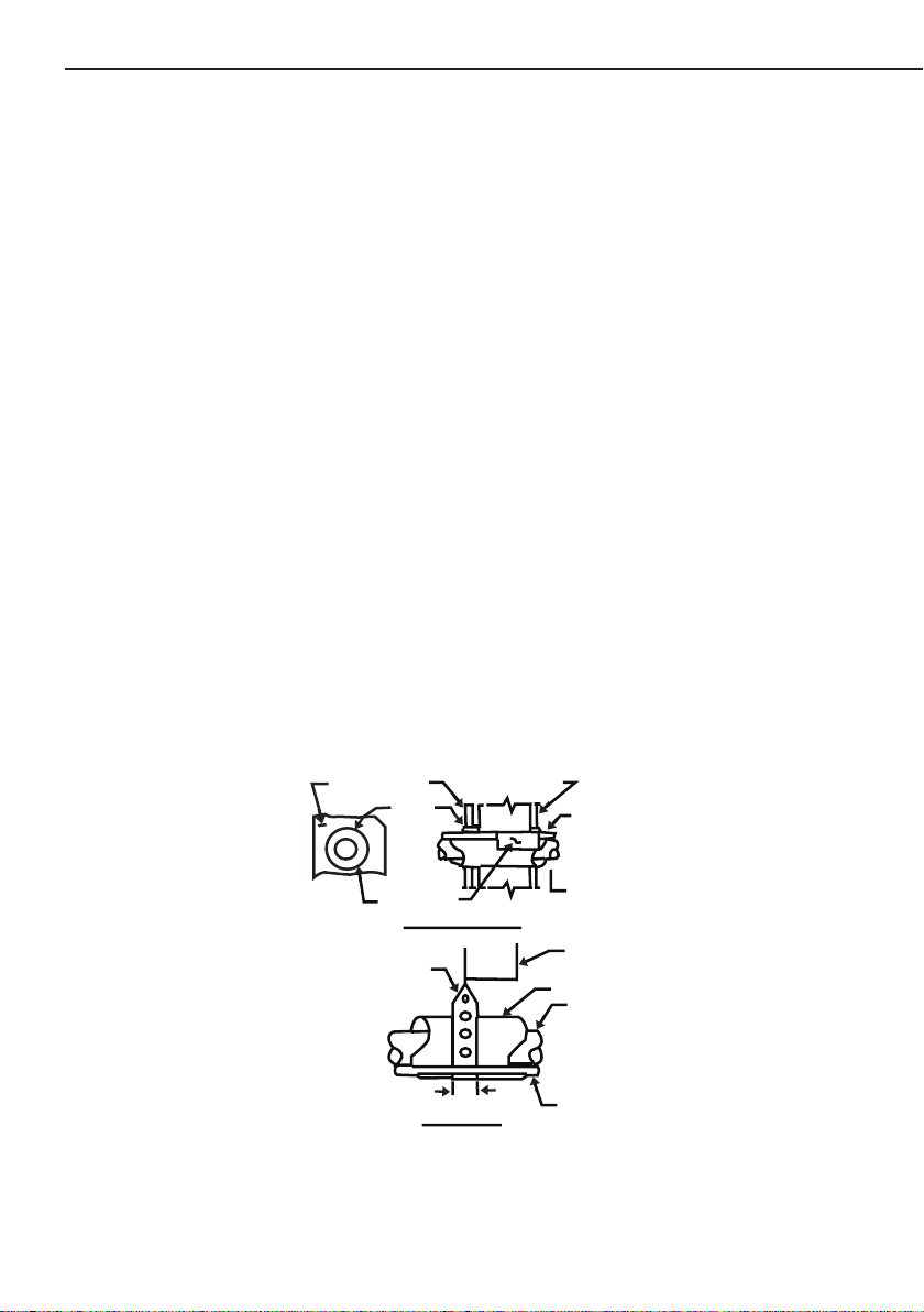
4. Check Piston
There is a piston located in outdoor condensing unit, please verify the piston size based on the
below table. When matching with air handler, please make sure replace this piston in air handler.
Table 3
OUTDOOR UNIT INDOOR UNIT PISTON KIT PART NO.
MAC13018 MAH13018 053
MAC13024 MAH13024 054
MAC13030 MAH13030 064
MAC13036 MAH13036 067
MAC13042 MAH13042 071
MAC13048 MAH13048 079
MAC13060 MAH13060 084
MHP13018 MAH13018 055
MHP13024 MAH13024 057
MHP13030 MAH13030 068
MHP13036 MAH13036 067
MHP13042 MAH13042 073
MHP13048 MAH13048 082
MHP13060 MAH13060 091
Liquid line orifice housing
Distributor assembly
Brass nut
Fig.10
For more details visit www.MrCool.com
9
Fixed orifice
Teflon ring
Liquid line assembly
(includes strainer)
Liquid line
Vapor line
Page 13

Unitary Ducted Split AC & HP
5. Operating Gauge Set and Service Valves
These instructions are intended as a general guide and do not supersede local codes in any
way. Consult authorities who have jurisdiction before installation.
5.1 Torque Requirements
When servicing or repairing heating, ventilating, and air conditioning components, ensure the
fasteners are appropriately tightened. Table 4 lists torque values for fasteners.
IMPORTANT
Only use Allen wrenches of sufcient hardness (50Rc −Rockwell Harness Scale minimum).
Fully insert the wrench into the valve stem recess.
Service valve stems are factory−torqued (from 9 ft−lbs for small
valves, to 25 ft−lbs for large valves) to prevent refrigerant loss during shipping and handling.
Using an Allen wrench rated at less than 50Rc risks rounding or breaking off the wrench, or
stripping the valve stem recess.
To prevent stripping of the various caps used, the appropriately sized wrench should be used
and tted snugly over the cap before tightening.
Table 4. Torque Requirements
Parts Recommended Torque
Service valve cap 8 ft.− lb. 11 NM
Sheet metal screws 16 in.− .lb 2 NM
Machine screws #10 28 in.− lb. 3 NM
Compressor bolts 90 in.− lb. 10 NM
Gauge port seal cap 8 ft.− lb. 11 NM
5.2 Using Manifold Gauge Set
When checking the system charge, only use a manifold gauge set that features low loss anti−
blow back ttings.
Manifold gauge set used with HFC−410A refrigerant systems must be capable of handling the
higher system operating pressures. The gauges should be rated for use with pressures of 0 − 800
psig on the high side and a low side of 30" vacuum to 250 psig with dampened speed to 500 psig.
Gauge hoses must be rated for use at up to 800 psig of pressure with a 4000 psig burst rating.
5.3 Operating Service Valves
The liquid and vapor line service valves are used for removing refrigerant, ushing, leak testing,
evacuating, checking charge and charging.
Each valve is equipped with a service port which has a factory−installed valve stem. Figure 11
provides information on how to access and operating both angle service valves.
5.4 Operating Angle Type Service Valve
1). Remove stem cap with an appropriately sized wrench.
2). Use a service wrench with a hex−head extension (3/16" for liquid line valve sizes and 5/16"
for vapor line valve sizes) to back the stem out counterclockwise as far as it will go.
For more details visit www.MrCool.com
10
Page 14

Unitary Ducted Split AC & HP
To indoor unit
Service port cap
Service valve
(Back-seated opened)
To outdoor unit
Service port core
(valve stem shown open)
Insert hex wrench here
Stem cap
Service valve
(Front-seated closed)
Fig.11
5.5 To Access Service Port
A service port cap protects the service port core from contamination and
serves as the primary leak seal.
1). Remove service port cap with an appropriately sized wrench.
2). Connect gauge set to service port.
3). When testing is completed, replace service port cap and tighten as follows
● With torque wrench: Finger tighten and torque cap per table 4.
● Without torque wrench: Finger tighten and use an appropriately sized
wrench to turn an additional 1/6 turn clockwise.
5.6 Reinstall Stem Cap
Stem cap protects the valve stem from damage and serves as the primary
seal. Replace the stem cap and tighten as follows:
● With Torque Wrench: Finger tighten and then torque cap per table 4.
● Without Torque Wrench: Finger tighten and use an appropriately sized
wrench to turn an additional 1/12 turn clockwise.
NOTE: A label with specific torque requirements may be affixed to the
stem cap. If the label is present, use the specied torque.
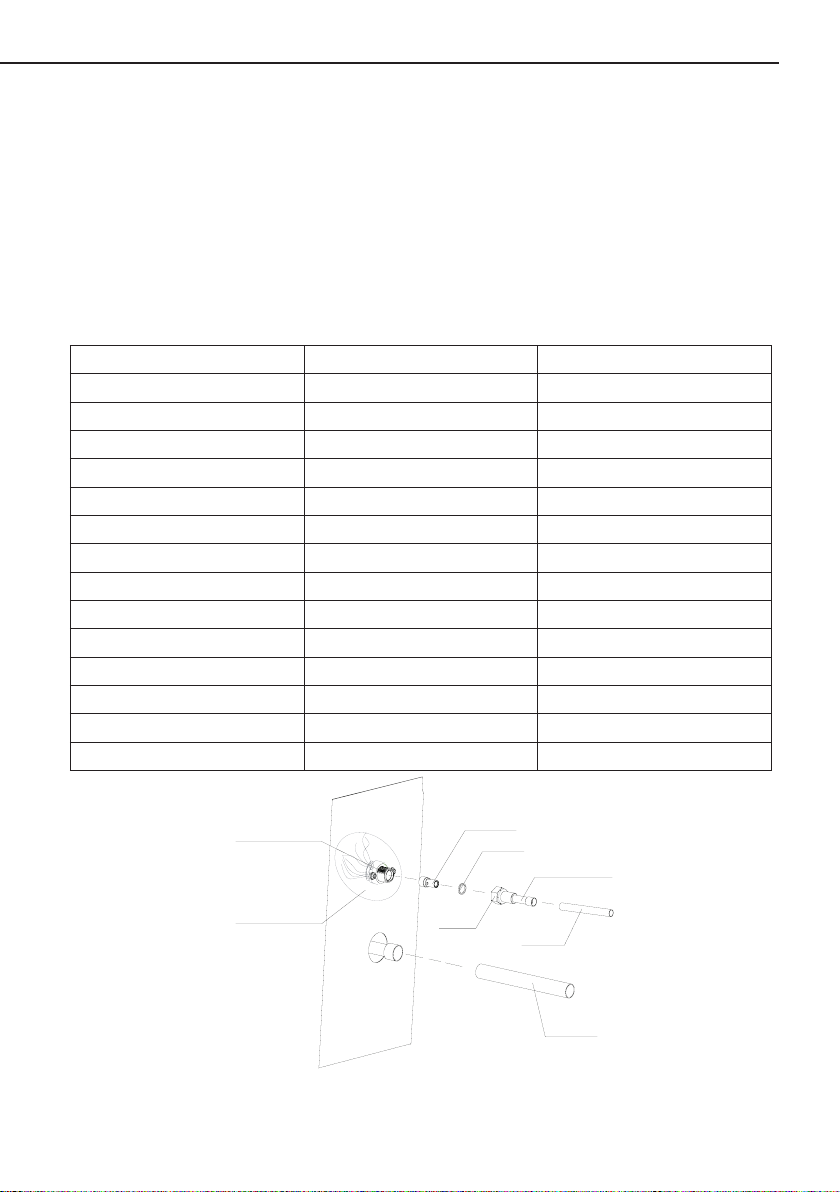
5.7 Install Liquid Line Filter Drier Indoor
Refer to Fig. 12 and install lter drier as follows:
1). Braze 5 in. liquid tube to the indoor coil.
2). Wrap lter drier with damp cloth.
3). Braze lter drier to 5 in. long liquid tube from step 1.
4). Connect and braze liquid refrigerant tube to the lter drier.
( Valve stem shown closed)
Insert hex wrench here
Fig.12—Liquid Line Filter Drier
For more details visit www.MrCool.com
11
Page 15

Unitary Ducted Split AC & HP
6. Recovering Refrigerant from Existing System
6.1 Disconnect Power
Disconnect all power to the existing outdoor unit at the disconnect switch or main fuse box/
breaker panel.
6.2 Connect Manifold Gauge Set
Connect a gauge set, clean recovery cylinder and a recovery machine to the service ports of
the existing unit. Use the instructions provided with the recovery machine to make the connections.
Main Fuse Box/Breaker Panel
Disconnect Switch
Recovery Machine
Manifold Gauges
Low
High
Clean Recovery Cylinder
Fig.13
Outdoor Unit
6.3 Recovering Refrigerant
Remove existing HCFC−410A refrigerant using one of the following procedures:
METHOD 1:
Us this method if the existing outdoor unit is not equipped with shut−off valves, or if the unit is
not operational and you plan to use the existing HCFC−410A to ush the system.
Remove all HCFC−410A refrigerant from the existing system. Check gauges after shutdown to
conrm that the entire system is completely void of refrigerant.
METHOD 2:
Use this method if the existing outdoor unit is equipped with manual shut−off valves, and you
plan to use new HCFC−410A refrigerant to ush the system.
The following devices could prevent full system charge recovery into the outdoor unit:
● Outdoor unit’s high or low−pressure switches (if applicable) when tripped can cycle the
compressor OFF.
● Compressor can stop pumping due to tripped internal pressure relief valve.
● Compressor has internal vacuum protection that is designed to unload the scrolls
(compressor stops pumping) when the pressure ratio meets a certain value or when the suction
pressure is as high as 20 psig. (Compressor suction pressures should never be allowed to go into
a vacuum. Prolonged operation at low suction pressures will result in overheating of the scrolls and
permanent damage to the scroll tips, drive bearings and internal seals.)
Once the compressor can not pump down to a lower pressure due to one of the above system
conditions, shut off the vapor valve. Turn OFF the main power to unit and use a recovery machine
to recover any refrigerant left in the indoor coil and line set.
For more details visit www.MrCool.com
12
Page 16

Unitary Ducted Split AC & HP
Perform the following task:
a. Start the existing HCFC−410A system in the cooling mode and close the liquid line valve.
b. Use the compressor to pump as much of the existing HCFC−410A refrigerant into the
outdoor unit until the outdoor system is full. Turn the outdoor unit main power OFF and use
a recovery machine to remove the remaining refrigerant from the system.
NOTE: It may be necessary to bypass the low pressure switches (if equipped) to ensure
complete refrigerant evacuation.
c. When the low side system pressures reach 0 psig, close the vapor line valve.
d. Check gauges after shutdown to conrm that the valves are not allowing refrigerant to ow
back into the low side of the system.
6.4 Leak Test Line Set and Indoor Coil
Fig.14—Leak Test
6.4.1 Connect Gauge Set
1). Connect an HFC−410A manifold gauge set high pressure hose to the vapor valve service
port.
NOTE: Normally, the high pressure hose is connected to the liquid line port. However,
connecting it to the vapor port better protects the manifold gauge set from high pressure damage.
2). With both manifold valves closed, connect the cylinder of HFC−410A refrigerant to the center
port of the manifold gauge set.
NOTE: Later in the procedure, the HFC−410A container will be replaced by the nitrogen
container.
6.4.2 Test For Leaks
After the line set has been connected to the indoor and outdoor units, check the line set
connections and indoor unit for leaks. Use the following procedure to test for leaks:
1). With both manifold valves closed, connect the cylinder of HFC−410A refrigerant to the center
For more details visit www.MrCool.com
13
Page 17

Unitary Ducted Split AC & HP
port of the manifold gauge set. Open the valve on the HFC−410A cylinder (vapor only).
2). Open the high pressure side of the manifold to allow HFC−410A into the line set and indoor
unit. Weigh in a trace amount of HFC−410A. [A trace amount is a maximum of two ounces
(57 g) refrigerant or three pounds (31 kPa) pressure]. Close the valve on the HFC−410A
cylinder and the valve on the high pressure side of the manifold gauge set. Disconnect the
HFC−410A cylinder.
3). Connect a cylinder of dry nitrogen with a pressure regulating valve to the center port of the
manifold gauge set.
4). Adjust dry nitrogen pressure to 150 psig (1034 kPa). Open the valve on the high side of the
manifold gauge set in order to pressurize the line set and the indoor unit.
5). After a few minutes, open one of the service valve ports and verify that the refrigerant added
to the system earlier is measurable with a leak detector.
6). After leak testing disconnect gauges from service ports.
6.5 Evacuating Line Set and Indoor Coil
Fig.15—Evacuating System
6.5.1 Connect Gauge Set
NOTE : Remove cores from service valves (if not already done).
1). Connect low side of manifold gauge set with 1/4 SAE in−line tee to vapor line service valve
2). Connect high side of manifold gauge set to liquid line service valve
3). Connect micron gauge available connector on the 1/4 SAE in−line tee.
4). Connect the vacuum pump (with vacuum gauge) to the center port of the manifold gauge
The center port line will be used later for both the HFC−410A and nitrogen containers.
set.
6.5.2 Connect Gauge Set
1). Open both manifold valves and start the vacuum pump.
2). Evacuate the line set and indoor unit to an absolute pressure of 23,000 microns (29.01
inches of mercury).
NOTE : During the early stages of evacuation, it is desirable to close the manifold gauge valve
at least once. A rapid rise in pressure indicates a relatively large leak. If this occurs, repeat the leak
For more details visit www.MrCool.com
14
Page 18

Unitary Ducted Split AC & HP
testing procedure.
NOTE: The term absolute pressure means the total actual pressure within a given volume
or system, above the absolute zero of pressure. Absolute pressure in a vacuum is equal to
atmospheric pressure minus vacuum pressure.
3). When the absolute pressure reaches 23,000 microns (29.01 inches of mercury), perform the
following:
● Close manifold gauge valves
● Close valve on vacuum pump
● Turn off vacuum pump
● Disconnect manifold gauge center port hose from vacuum pump
● Attach manifold center port hose to a dry nitrogen cylinder with pressure regulator set to 150
psig (1034 kPa) and purge the hose.
● Open manifold gauge valves to break the vacuum in the line set and indoor unit.
● Close manifold gauge valves.
4). Shut off the dry nitrogen cylinder and remove the manifold gauge hose from the cylinder.
Open the manifold gauge valves to release the dry nitrogen from the line set and indoor unit.
5). Reconnect the manifold gauge to the vacuum pump, turn the pump on, and continue to
evacuate the line set and indoor unit until the absolute pressure does not rise above 500
microns (29.9 inches of mercury) within a 20−minute period after shutting off the vacuum
pump and closing the manifold gauge valves.
6). When the absolute pressure requirement above has been met, disconnect the manifold hose
from the vacuum pump and connect it to an upright cylinder of HFC−410A refrigerant. Open
the manifold gauge valve 1 to 2 psig in order to release the vacuum in the line set and indoor
unit.
7). Perform the following:
● Close manifold gauge valves.
● Shut off HFC−410A cylinder.
● Reinstall service valve cores by removing manifold hose from service valve.
Quickly install cores with core tool while maintaining a positive system pressure.
● Replace stem caps and secure nger tight, then tighten an additional one−sixth (1/6) of a turn
as illustrated.
7. Electrical
In the U.S.A., wiring must conform with current local codes and the current National Electric
Code (NEC). In Canada, wiring must conform with current local codes and the current Canadian
Electrical Code (CEC).
Refer to the furnace or air handler installation instructions for additional wiring application
diagrams and refer to unit nameplate for minimum circuit ampacity and maximum overcurrent
protection size.
24VAC TRANSFORMER
Use the transformer provided with the furnace or air handler for low-voltage control power
(24VAC − 40 VA minimum).
For more details visit www.MrCool.com
15
Page 19

Unitary Ducted Split AC & HP
7.1 Size Circuit And Install Disconnect Switch
Refer to the unit nameplate for minimum circuit ampacity, and maximum fuse or circuit breaker
(HACR per NEC). Install power wiring and properly sized disconnect switch.
Main Fuse Box/Breaker Panel
Disconnect Switch
Fig.16
NOTE: Units are approved for use only with copper conductors. Ground unit at disconnect
switch or to an earth ground.
7.2 Install Thermostat
Install room thermostat (ordered separately) on an inside wall approximately in the center of
the conditioned area and 5 feet (1.5m) from the oor. It should not be installed on an outside wall or
where it can be affected by sunlight or drafts.
Fig.17
NOTE: 24VAC, Class II circuit connections are made in the control panel.
7.3 Unit Low Voltage Connections
High voltage eld wiring
Low voltage (24v) eld wiring
For more details visit www.MrCool.com
16
Page 20

Unitary Ducted Split AC & HP
Table 5
WIRE RUN LENGTH AWG# INSULATION TYPE
LESS THAN 100’ (30 METERS) 18 Temperature Rating
MORE THAN 100’ (30 METERS) 16 35°C Minimum
A Run 24VAC control wires through cutout with grommet.
B Run 24VAC control wires through wire tie.
C Make 24VAC control wire connections.
NOTE: Wire tie provides low voltage wire strain relief and to maintain separation
of eld low and high voltage circuits
NOTE: For proper voltages, select thermostat wire (control wires)gauge per
table above.
NOTE: Do not bundle any excess 24VAC control wires inside control box.
7.4 Unit High Voltage Connections
A Run HIGH VOLTAGE control wires through cutout with grommet.
B Make HIGH VOLTAGE control wires connections.
C Tighten wire tie to security HIGH VOLTAGE control wiring.
NOTE: Any excess high voltage eld wiring should be trimmed
and secured away from any low voltage eld wiring
NOTE: To facilitate a conduit, a cutout is located in the bottom of the control
box. Connect conduit to the control box using a proper conduit tting.
NOTE: The signal line of the wired controller must be separated from the power
line and the connecting line between the indoor unit and the outdoor unit.
Important Electric Data
Table 6
Compressor
Model
MAC13018 208/230/1/60 1 7.9 38 1.2 15 AWG16
MAC13024 208/230/1/60 1 9.8 53 1.2 20 AWG14
MAC13030 208/230/1/60 1 12.6 71 1.2 25 AWG12
MAC13036 208/230/1/60 1 15.08 64 1.7 35 AWG12
MAC13042 208/230/1/60 1 21.5 105 1.7 50 AWG10
MAC13048 208/230/1/60 1 21 115 1.7 45 AWG10
MAC13060 208/230/1/60 1 25 150 2.1 50 AWG8
MHP13018 208/230/1/60 1 7.5 38 0.8 15 AWG16
MHP13024 208/230/1/60 1 9.8 53 1.2 20 AWG14
MHP13030 208/230/1/60 1 12.5 71 0.7 25 AWG12
Power Supply Qty. RLA LRA FLA
V/Ph/Hz - A A A A AWG
Fan
Motor
Fuse/Breaker
Capacity
Min. Power
Supply Cord
For more details visit www.MrCool.com
17
Page 21

Unitary Ducted Split AC & HP
MHP13036 208/230/1/60 1 15.08 64 1.7 35 AWG12
MHP13042 208/230/1/60 1 17 112 1.7 35 AWG10
MHP13048 208/230/1/60 1 21 115 1.7 45 AWG10
MHP13060 208/230/1/60 1 24.5 134 2.3 50 AWG8
Electric Wiring Design
Model:MAC13018; MAC13024; MAC13030; MAC13036; MAC13042;
MAC13048; MAC13060.
L1
L2
T1
T2
G
C
R
Y1
Fig.18
Model: MHP13018; MHP13024; MHP13030; MHP13036.
KM
G
XT2
C
R
Y1
W1
T1
T2
L1
L2
Ground
L1
L2
Outdoor
Unit
L1
L2
Ground
C
R
W1
Y1
O
POWER
208/230V
1PH 60HZ
POWER
208/230V
1PH 60HZ
THERMOSTAT
G
C
R
Y1
THERMOSTAT
W1
Model: MHP13042; MHP13048; MHP13060.
For more details visit www.MrCool.com
Fig.19
18
Page 22

Unitary Ducted Split AC & HP
XT1
POWER
L1
L2
L1
L2
208/230V
1PH 60HZ
Ground
G
XT2
C
Outdoor
Unit
R
Y1
O
W1
Fig.20
18-36k Circuit Diagram
Model:MAC13018; MAC13024; MAC13030; MAC13036.
L1
T1
T2
L2
KM
BK
Fan motor
G
A2
W7
X12
P
BU
HP
LP
W6
X10
WH
WH
P
OG
AP
X8
X7
A1
W5
C
FAN
HERM
W3
W2
W1
CAPACITOR
RD
YEGN
G
BN
M
~
G
R
S
C
COMP
~
Compressor
G
W4
G
G
C
R
Y1
O
THERMOSTAT
W1
POWER
RT
50K
CN3
W12
X3
W11
R
W10
C
RT
AP
KM
OUTDOOR UNIT
XT
24V~INPUT
Y1
24V~INPUT
R
COM
C
discharge temperature
sensor
MAIN BOARD
AC Contactor
Y1
R
C
Lug Plate 1
THERMOSTAT
Fig.21
For more details visit www.MrCool.com
19
Page 23

42-60k Circuit Diagram
Model:MAC13042; MAC13048; MAC13060.
Unitary Ducted Split AC & HP
OUTDOOR UNIT
THERMOSTAT
Lug Plate 1
~
~
Fig.22
18-36k Circuit Diagram
Model: MHP13018; MHP13024; MHP13030; MHP13036.
KM
T1
L1
T2
L2
A1
W16
C
FAN
HERM
CAPACITOR
4YV
XT1
RD
BK
BN
M
~
G
Fan motor
YEGN
G
W5
W3W2
W1
R
S
C
COMP
~
Compressor
G
W4
G
P
1
HP
P
LP
W12
W13
Notes:
'O1'is used when under testing,
connected with 'O' of indoor
unit, usually suspended.
G
A2
W11
KM
K2
X12
(AC-L)
W15
X13
BU
X10
WH
X8
WH
X7
K2
OG
(OFAN-H)
W22
2
W23
XT1
Fig.23
For more details visit www.MrCool.com
20
RT1
CN1
AP
K5
(OFAN-L)
OUTDOOR UNIT
POWER
RT2
W25
20K
50K
R
θ
20K
θ
CN3
KM-L2
CN5
X14
W14
W21
X3
W20
X2
W19
X1
W18
R
W17
C
AP
RT1
RT2
4YV
KM
XT2
24V~INPUT
24V~INPUT
24V~INPUT
24V~INPUT
COM
Y1
O
W1
R
C
O
Y1
O
W1
R
C
O1
MAIN BOARD
Pipe temperature Sensor
discharge temperature
sensor
4-WAY VALVE
AC Contactor
THERMOSTAT
Indoor
Lug Plate 1
Page 24

Unitary Ducted Split AC & HP
42-60k Circuit Diagram
Model:MHP13042; MHP13048; MHP13060.
Fig.24
8. System Refrigerant
This section outlines procedures for:
● Connecting gauge set for testing and charging.
● Adding or removing refrigerant.
8.1 Gauge Set (Cooling Only)
Connections for testing and charging.
A Close manifold gauge set valves and connect the center hose to a cylinder of HFC−410A.
Set for liquid phase charging.
B Connect the manifold gauge set’s low pressure side to the suction line service port.
C Connect the manifold gauge set’s high pressure side to the liquid line service port.
D Position temperature sensor on vapor line near liquid line service port.
For more details visit www.MrCool.com
21
Page 25

Unitary Ducted Split AC & HP
Figure 25. Gauge Set Setup and Connections for cooling only
8.2 Gauge Set (Heat Pump)
Connections for testing and charging.
A Close manifold gauge set valves and connect the center hose to a cylinder of HFC−410A.
Set for liquid phase charging.
B Connect the manifold gauge set’s low pressure side to the true suction port.
C Connect the manifold gauge set’s high pressure side to the liquid line service port.
D Position temperature sensor on the suction line near the compressor.
Figure 26. Gauge Set Setup and Connections for heat pump
For more details visit www.MrCool.com
22
Page 26

Unitary Ducted Split AC & HP
8.3 Weigh In
Calculating system charge for outdoor unit void of charge
If the system is void of refrigerant, first, locate and repair any leaks and then weigh in the
refrigerant charge into the unit. To calculate the total refrigerant charge:
Amount specified
on nameplate
Refrigerant Charge per Line Set Length:
Outdoor Unit
COOLING ONLY
HEAT PUMP
*If line length is greater than 25 ft. (7.6 m), add this amount. If line length is less than 25 ft. (7.6
m), subtract this amount.
NOTE: Insulate liquid line when it is routed through areas where the surrounding ambient
temperature could become higher than the temperature of the liquid line or when pressure drop is
equal to or greater than 20 psig.
NOTE: The above nameplate is for illustration purposes only. Go to actual nameplate on
outdoor unit for charge information.
Adjust amount for variation
in line set length listed on
+
Total charge
=
line set length table below
Table 7
Liquid Line
Set Diameter
3/8" (9.5 mm) 1.6 ounce per 5 feet (45g per 1.5 m)
1/2"(12.7 mm) 3.2 ounce per 5 feet (90g per 1.5 m)
3/8" (9.5 mm) 2.9 ounce per 5 feet (81g per 1.5 m)
1/2"(12.7 mm) 5.9 ounce per 5 feet (165g per 1.5 m)
Ounces per 5 feet (g per 1.5 m)
adjust from 25 feet (7.6 m) line set*
For more details visit www.MrCool.com
23
Page 27

Unitary Ducted Split AC & HP
Wet Bu lb (air entering indoor coil)
50
55
60
65
70
75
80
40
15
21
29
35
43
49
56
45
13
19
27
34
41
47
54
50
11
17
25
32
39
45
52
55 9 15
23
31
38
43
49
60 7 13
21
28
35
41
47
65 - 11
19
25
33
39
45
70 - 8
16
22
30
37
43
75 - -
12
19
28
35
40
85 - - - 13
22
31
35
90 - - - 11
20
29
33
95 - - - 8
18
27
31
100 - - - -
16
26
29
105 - - - -
13
24
28
110 - - - -
11
22
27
115 - - - - 8 20
25
START: Measure outdoor ambient temperature
40℉(4.4℃) and above 39℉(3.8℃) and below
USE WEIGH-IN METHOD
Weigh-in or remove refrigerant
based upon line length
SH°(Superheat) Values (+/℉)
℉*
80 - - 8 16 25 33 37
ABOVE or BELOW
If value is LESS than
shown, then REMOVE
refrigerant.
MORE or LESS
If refrigerant is
REMOVED, retest
to confirm that unit
is properly charged.
If value is MORE than shown,
then ADD refrigerant.
Figure 27. HFC−410A Superheat RFC Method
For more details visit www.MrCool.com
24
If refrigerant is ADDED,
retest to confirm that unit
is properly charged.
Page 28

Unitary Ducted Split AC & HP
Table 8. Normal Operating Pressures − Liquid +10 and Vapor +5 PSIG* (All Models)
) **
℉(℃
60(15) 346/139 352 / 138 338 / 137 350 / 134
50(10) 323/117 331/114 334/112 331/117
40(4) 306/98 304/99 312/93 313/97
30(-1) 278/84 299/80 302/74 298/83
20(-7) 273/66 283/66 280/53 284/66
65(18) 226/140 233/137 238/138 220/138
70(21) 244/141 252/138 263/139 236/140
75(24) 263/142 271/140 279/139 256/141
80(27) 283/143 292/141 299/140 276/142
85(29) 302/144 314/142 324/141 298/143
90(32) 328/145 338/143 340/142 321/144
95(35) 351 / 146 361 / 145 375 / 145 344 / 144
100(38) 376 / 147 387 / 146 397 / 145 369 / 146
105(41) 402 / 148 412 / 147 424 / 147 394 / 147
110(43) 430 / 149 441 / 148 454 / 150 421 / 148
115(46) 465 / 150 471 / 151 485 / 150 449 / 149
*IMPORTANT—These are most popular match−up pressures. Indoor match up, indoor air quality, and
indoor load cause pressures to vary.
**Temperature of the air entering the outside coil.
) **
℉(℃
60(15) 373 / 139 355/130 351/117
50(10) 363/117 336/113 333/105
40(4) 348/97 315/88 316/88
30(-1) 336/74 296/72 308/70
20(-7) 322/64 286/64 300/61
65(18) 223/125 231/136 243/136
70(21) 241/130 248/139 263/137
75(24) 261/134 271/140 282/138
MHP13018 MHP13024 MHP13030 MHP13036
Liquid / Vapor Liquid / Vapor Liquid / Vapor Liquid / Vapor
Heating
Cooling
MHP13042 MHP13048 MHP13060
Liquid / Vapor Liquid / Vapor Liquid / Vapor
Heating
Cooling
For more details visit www.MrCool.com
25
Page 29

Unitary Ducted Split AC & HP
80(27) 282/138 291/142 306/139
85(29) 302/139 312/143 327/140
90(32) 326/140 335/144 351/141
95(35) 349 / 141 359 / 145 376 / 142
100(38) 374 / 142 384 / 146 401 / 143
105(41) 399 / 143 411 / 148 426 / 145
110(43) 428 / 145 439 / 149 452 / 146
115(46) 455 / 146 468 / 150 484 / 148
*IMPORTANT—These are most popular match−up pressures. Indoor match up, indoor air quality, and
indoor load cause pressures to vary.
**Temperature of the air entering the outside coil.
Table 9. HFC−410A Temperature (°F) − Pressure (Psig)
Psig
℉
32 100.8 48 137.1 63 178.5 79 231.6 94 290.8 110 365.0 125 445.9 141 545.6
33 102.9 49 139.6 64 181.6 80 235.3 95 295.1 111 370.0 126 451.8 142 552.3
34 105.0 50 142.2 65 184.3 81 239.0 96 299.4 112 375.1 127 457.6 143 559.1
35 107.1 51 144.8 66 187.7 82 242.7 97 303.8 113 380.2 128 463.5 144 565.9
36 109.2 52 147.4 67 190.9 83 246.5 98 308.2 114 385.4 129 469.5 145 572.8
37 111.4 53 150.1 68 194.1 84 250.3 99 312.7 115 390.7 130 475.6 146 579.8
38 113.6 54 152.8 69 197.3 85 254.1 100 317.2 116 396.0 131 481.6 147 586.8
39 115.8 55 155.5 70 200.6
40 118.0 56 158.2 71 203.9 87 262.0 102 326.4 118 406.7 133 494.0 149 601.0
41 120.3 57 161.0 72 207.2 88 266.0 103 331.0 119 412.2 134 500.2 150 608.1
42 122.6 58 163.9 73 210.6 89 270.0 104 335.7 120 417.7 135 506.5 151 615.4
43 125.0 59 166.7 74 214.0 90 274.1 105 340.5 121 423.2 136 512.9 152 622.7
44 127.3 60 169.6 75 217.4 91 278.2 106 345.3 122 428.8 137 519.3 153 630.0
45 129.7 61 172.6 76 220.9 92 282.3 107 350.1 123 434.5 138 525.8 154 637.5
46 132.2 62 175.4 77 224.4 93 286.5 108 355.0 124 440.2 139 532.4 155 645.0
47 134.6 78 228.0 109 360.0 140 539.0
Psig
℉
Psig
℉
Psig
℉
86 258.0 101 321.8 117 401.3 132 487.8 148 593.8
Psig
℉
Psig
℉
Psig
℉
Psig
℉
For more details visit www.MrCool.com
26
Page 30

Unitary Ducted Split AC & HP
9. Unit Control
9.1 Mainboard Description
Pressure switch
circuit connections
Sensor plug in
(Discharge sensor)
+12V common
terminal
Fig.28 Mainboard Description for cooling only
24V terminal
strip connections
24V terminal
strip connections
Diagnostic leds
+12V common
terminal
Disagnostic
display
24V terminal strip connections
Temp. Sensors plug in
Pressure switch
circuit connections
24V terminal
strip connections
Connections for fan motor
Fig.29 Mainboard Description for Heat pump unit
For more details visit www.MrCool.com
27
Page 31

Unitary Ducted Split AC & HP
9.2 Terminal Description
Table 10. Demand Control Board Description for cooling only unit
ID Description
X12(Y-OUT) 24 VAC output connection for compressor operation
X7(LPP) Connection for low−pressure switch
X10(HPP) Connection for high−pressure switch
X3(Y) 24 VAC input for compressor operation
CN3(T-PIPE) Connection for discharge temperature sensor.
X16(C) 24 VAC system common
X15(R) 24 VAC system power input
X8(+12V) Connection for low−pressure switch Connection for high−pressure switch
Table 11. Demand Control Board Description for Heat pump unit
ID Description
X1(W-OUT) Auxiliary electrical heater output
X2(O) Connection for detecting the 24VAC control signal of 4-way valve
X3(Y) Connection for detecting the 24VAC signal for compressor
X7(LPP) Connection for low pressure switch
X8(+12V) Connection for low pressure switch, Connection for high pressure switch
X10(HPP) Connection for high pressure switch
X12(Y-OUT) 24 VAC output interface for compressor operation
X13(O-OUT) 24 VAC output interface for 4-way valve operation
X14(N) 220 VAC N input of fan motor
X15(R) 24 VAC system power input
X16(C) 24 VAC system common
CN1(T-DF) Connection for temp.sensor of condenser
CN2(OUTROOM) Connection for ambient temp.sensor
CN3(T-PIPE) Connection for discharge temp.sensor
CN5(TUBE) Connect 20k xed resistance into reserved interface
K2-2(OFAN-H) 220VAC output for high speed of fan motor
K2-4(AC-L) 220VAC L input for high speed of fan motor
K5-2(OFAN-L) 220VAC output for low speed of fan motor
K5-4(AC-L) 220VAC L input for low speed of fan motor
For more details visit www.MrCool.com
28
Page 32

Unitary Ducted Split AC & HP
9.3 Control Flowchart
Cooling Operation Heating Operation
Power
On
Power
On
Choose cooling model
Indoor fan run
Satisfying open
Comp. condition
Y
Comp. and outdoo r
fan run
Temp of indoo r
≤
Set temp
Y
Comp. and
outdoo r fan stop
Choose heaingt
model
Satisfying open
N
comp. condition
N
Y
Comp. and outdoo r
fan run
Temp of indoo r
N
≥Set temp
N
Y
Comp. and
outdoo r fan stop
Comp. stop
for 3 min
NY
Y
For more details visit www.MrCool.com
29
Comp. stop
for 3 min
N
Page 33

Unitary Ducted Split AC & HP
9.4 Error Analysis
COOLING ONLY
The state (Off, On, Flashing) of two LEDs on the control board (DS1 [Red] and DS2 [Red]) indicate
diagnostics conditions that are described in table 12. See table 12 to determine control board
operational conditions and to diagnose cause and solution to problems.
DS1 Red DS2 Red Trouble Case
OFF OFF
FAULT and LOCKOUT CODES (Each fault adds 1 strike to that code’s counter; 3 strikes per 30
minutes = LOCKOUT)
0.5s
Circulating
Flash
OFF
Circulating
DEMAND CONTROL BOARD DIAGNOSTICS
Table 12. Demand Control board Diagnostic LEDs
Origin of
Trouble
No power
(24V) to
demand
control board
terminals
R and C
or demand
control board
failure.
High pressure
switch
Low pressure
switch
OFF
0.5s
ash
Power
problem
Actuation of
high pressure
switch
Actuation of
low pressure
switch
Measure
1 Check control transformer power
(24V).
2 If power is available to demand
control board and LED(s) do not
light, replace control board.
Abnormality is detected when the
contact of the high pressure switch
opens for 3 sec. The system will
be shut down. The unit will report
this fault. For the rst two faults
within 30 minutes, the unit can be
recovered automatically. If over
three times, the unit cannot be
recovered automatically.
When the unit runs more than 4
minutes or does not run, the low
pressure switch opens for more
than3sec and the system will be
shut down..The unit will report
this fault. For the rst two faults
within 30 minutes, the unit can be
recovered automatically. If over
three times, the unit cannot be
recovered automatically.
For more details visit www.MrCool.com
30
Page 34

Unitary Ducted Split AC & HP
0.5s
Circulating
Flash
Continuous
Light
0.5s
Circulating
Flash
Continuous
Light
OFF
0.5s
Circulating
ash
Air discharge
high-
temperature
protection of
compressor
Malfunction
of exhaust
Temp. Sensor
Normal
operation
Exhaust over-
temperature
Protection
Exhaust
temperature
sensor
Unit operating
normally or
in standby
mode.
The exhaust temperature is higher
than 125°C for more than 5s, the
system will be shut down. After
stopping the compressor for 3
mins, if the exhaust temperature
is lower than 90°C for more than
5s, the compressor will re-start.
For the rst two faults within 30
minutes, the unit can be recovered
automatically. If over three times,
the unit cannot be recovered
automatically.
If the exhaust temperature
sensor is detected of open circuit
5 seconds successively after
the compressor is started for 3
minutes or short circuit 5 seconds
successively at any time The
system will be shut down. After the
fault is eliminated, the system can
automatically resume to operation
None required.
HEAT PUMP
Fault Display on the Dual 8 Numeral Tube of Outdoor Mainboard
Malfunction
code
E1
E3
Trouble case
Actuation
of high
pressure
switch
Actuation of
low pressure
switch
Origin of
trouble signal
High pressure
switch
Low pressure
switch
Abnormality is detected when the contact of the
high pressure switch opens for 3 sec. The system
will be shut down. The unit will report this fault. For
the rst two faults within 30 minutes, the unit can
be recovered automatically. If over three times, the
unit cannot be recovered automatically.
When the unit runs more than 4 minutes or does
not run, the low pressure switch opens for more
than3sec and the system will be shut down. The
unit will report this fault. For the rst two faults
within 30 minutes, the unit can be recovered
automatically. If over three times, the unit cannot be
recovered automatically.
For more details visit www.MrCool.com
31
Measure
Page 35

E4
F2
Air discharge
high-
temperature
protection of
compressor
Malfunction
of condenser
temperature
thermistor
Exhaust over-
temperature
protection
Condenser
temperature
thermistor
Unitary Ducted Split AC & HP
The exhaust temperature is higher than 125°C for
more than 5sec, the system will be shut down. After
stopping the compressor for 3 mins, if the exhaust
temperature is lower than 90°C for more than 5
sec, the compressor will re-start. For the rst two
faults within 30 minutes, the unit can be recovered
automatically. If over three times, the unit cannot be
recovered automatically.
Malfunction of condenser temperature thermistor
is detected when there is a short circuit or an open
circuit in the condenser temperature thermistor for
more than 5 sec. The system will be shut down. The
reset for the malfunction of condenser temperature
thermistor is automatic.
F3
F4
oN
H1
Malfunction
of outdoor
ambient
temperature
thermistor
Malfunction
of Exhaust
Temp.
Sensor
Normal
operation
Defrost
operation
Outdoor
ambient
temperature
thermistor
Exhaust
temperature
sensor
Unit operating
normally or
in standby
mode.
Unit operating
in defrost
Malfunction outdoor ambient temperature thermistor
is detected when there is a short circuit or an
open circuit in the outdoor ambient temperature
thermistor for more than 5 sec. The system will
be shut down. The reset for the malfunction of
condenser temperature thermistor is automatic.
If the exhaust temperature sensor is detected
of open circuit 5 seconds successively after the
compressor is started for 2 minutes or short circuit
5 seconds successively at any time .The system
will be shut down. After the fault is eliminated, the
system can automatically resume to operation.
None required.
None required.
For more details visit www.MrCool.com
32
Page 36

Unitary Ducted Split AC & HP
9.5 Setting on Defrost Control PCB (for Heat Pump unit only)
There are 5 different defrost control setting you can choose by change the dip switch located
on Defrost Control PCB.
ON
12
DIP ON
3
DIP ON
12 3
DIP ON
12 3
DIP ON
12 3
DIP
12 3
000 001 010 011 100
Fig.30
Table 13
Without Outdoor Ambient
Sensor installed
Dip Switch Setting 000 001 010 011 100
t(min) 44 44 60 90 30
T1
T2
28 ℉ 23 ℉ 32 ℉ 32 ℉ 32 ℉
59 ℉ 59 ℉ 68 ℉ 68 ℉ 68 ℉
t-----------Accumulation of compressor running time
T1----------Initiation Coil T emperature
T2---------Termination Coil Temperature
The factory default setting is “000”. After the compressor consecutively runs for 44 minutes,
the defrost cycle will be initiated if the sensor detects the coil temperature ≤ 28 F for consecutive
1 minute. The defrost cycle will be terminated either the coil temperature reach 59 F or the defrost
cycle reach 15 minutes.
Defrost Cycle: when the system running in heat pump mode, after the compressor has been
running for “t” minutes continuously, the defrost cycle start if the defrosting temp sensor has been
in T1 degree or under T1 degree for 1 minute continuously. During the defrost cycle, the reversing
valve is energized, the outdoor fan stops running and the auxiliary electric heating is energized.
The defrost cycle will be terminated if defrost cycle reach 15 minutes or the coil sensor detects the
coil temperature over T2 degree.
9.6 Manually Defrost Cycle
There is a Manually Defrost Button located on the Defrost Control PCB, by press this button,
the system will go to defrost cycle right away to melt the ice on the coil.
For more details visit www.MrCool.com
33
Page 37

For more details visit www.MrCool.com
 Loading...