

Page 1

Please read this manual carefully before installation and keep it for future reference.
Installation & Owner’s
Manual
®
DIY
Due to updates and constantly improving performance, the information and instructions within this
manual are subject to change without notice. Please visit www.mrcool.com/documentation to
E Star™ Series
ensure you have the latest version of this manual.
Version Date: 12-30-20
Page 2
Contents
Safety Precautions
!
Warnings .................................................................................................................................. 3
Cautions ................................................................................................................................... 4
Parts Overview
1
Parts Diagram ......................................................................................................................... 5
Display Window ...................................................................................................................... 6
Accessories ................................................................................................................................... 7
Operating Instructions
2
Operating Temperature ......................................................................................................... 9
Manual Operation ................................................................................................................... 9
Care and Maintenance
3
DISCLAIMER: You are assuming the risk by handling materials containing refrigerants under pressure, that if not
handled properly, can cause bodily injury. If you do not feel comfortable conducting this installation process,
Page 1 mrcool.com
Page 3
Contents
4
Indoor Unit Installation ...........15
1. Selecting an installation location .........15
4. Prepare refrigerant piping ....................18
5. Mount indoor unit ..................................18
5
Outdoor Unit Installation ......
1. Selecting an installation location ......19
19
2. Install drain joint .................................20
Refrigerant Piping Connections......................23
1. Prepare Exterior Wall Hole ............................................. 23
2. Unwind Quick Connect® Line Set to necessary length 23
3. Connect Line Set to Indoor Unit ..................................... 24
4. Connect Line Set to Outdoor Unit ................................ 26
5. Opening Refrigerant Valves of Outdoor Unit ............... 28
6. Wrap Piping Connections ............................................... 29
7. Connect drain pipe .......................................................... 30
7
Electrical Connections .....................................32
.21
Electrical and Gas Leak Checks.......................34
8
9
Test Run..............................................................35
10
Troubleshooting................................................37
mrcool.com
Page 2
Page 4
Safety Precautions
Read Before Using
Incorrect usage may cause serious damage or injury.
The symbols below are used throughout this manual to indicate instructions that should
be followed closely or actions that should be avoided to prevent death, injury, and/or property damage.
This symbol indicates ignoring instructions may cause death or serious injury
WARNING
This symbol indicates ignoring instructions may cause bodily injury, damage
to the unit, or other surrounding property.
CAUTION
Safety Precautions
!
.
This symbol indicates that you should NEVER perform the indicated action.
WARNING
DISCLAIMER: You are assuming the risk by handling materials containing refrigerants under pressure, that if not
handled properly can cause bodily injury. If you do not feel comfortable conducting this installation process,
DO NOT
When connecting the refrigerant piping,
the unit. The presence of other gasses or substances will lower the unit’s capacity, and may
cause abnormally high pressure in the operation cycle. This could cause an explosion and/or
injury.
DO NOT
unit at all times.
1.
2.
DO NOT allow any other substances or gases enter
3.
4.
5.
Page 3
Install the unit in a firm, stable location that can support the weight of the unit. If the
installation location cannot support the weight of the unit, it could fall and cause serious injury
and/or damage.
Manual.
mrcool.com
Page 5
Safety Precautions
7.
. All wiring must be properly arranged to ensure that the control board cover can close properly.
8
If the control board cover is not closed properly, it can lead to corrosion, which can cause the
connection points on the terminal to overheat, which car result in fire and/or electrical shock.
If connecting power to fixed wiring, the following must be incorporated within it, in accordance with the wiring
9.
rules; an all-pole disconnection device (which has at least 3 mm of clearances in all poles), and have a leakage
current that may exceed 10mA, the residual current device (RCD) having a rated residual operating current not
exceeding 30mA, and disconnection all must be present.
10.
This appliance is not inteded for use by individuals (including children) with reduced physical, sensory, or mental
11.
capabilities. It is also not intended for use by individuals with a lack of experience or knowledge, unless they have
been given supervision or instruction concerning use of the appliance by a person responsible for their safety.
Children should be supervised at all time to ensure that they do not play with
the appliance.
DO NOT
combustible materials.
.
DO NOT
DO NOT
room. Exposure to excessive amounts of water may cause electrical components to short circuit.
DO NOT
DO NOT
operate your air conditioner in a room where it could be exposed to water, such as a bathroom or laundry
1.
2.
Note about Flourinated Gasses:
1
2.
the unit itself.
3.
4.
5.
mrcool.com
Page 4
Page 6
Safety Precautions
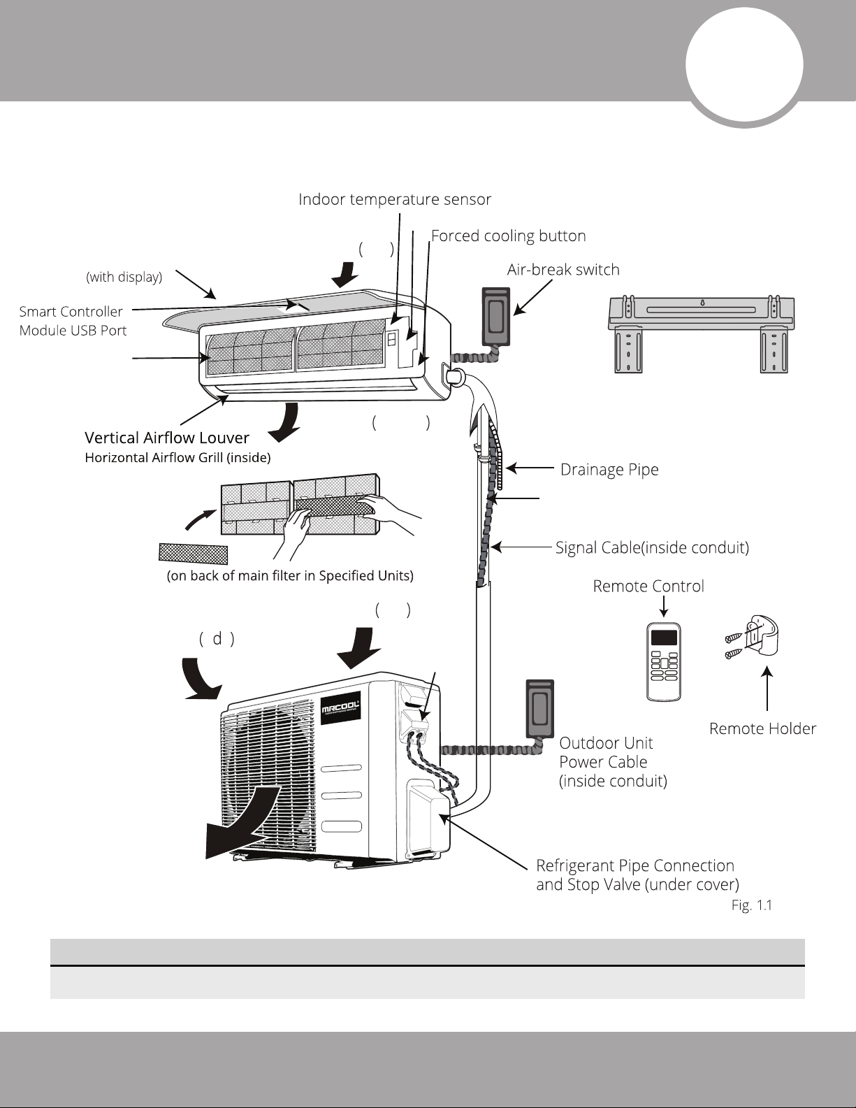
Parts Overview
1
NOTE: The installation must be performed in accordance with the requirement of local and
national standards. Both power cable and signal cable should be protected by the conduit.
Indoor Unit
(Interior/Air Handler)
Front Panel
Air Filter
Electrical Access
Air inlet rear
Air outlet bottom
Fresh Air Filter
Wall Mounting Plate
Quick Connect® Line Set
(refrigerant pipe)
Air inlet rear
Air inlet si e
Air outlet
Outdoor Unit
(Exterior/Condenser)
NOTE ON ILLUSTRATIONS
Illustrations in this manual are for explanatory purposes. The actual shape of your unit may vary.
Electrical
Access
Page 5
mrcool.com
Page 7
2
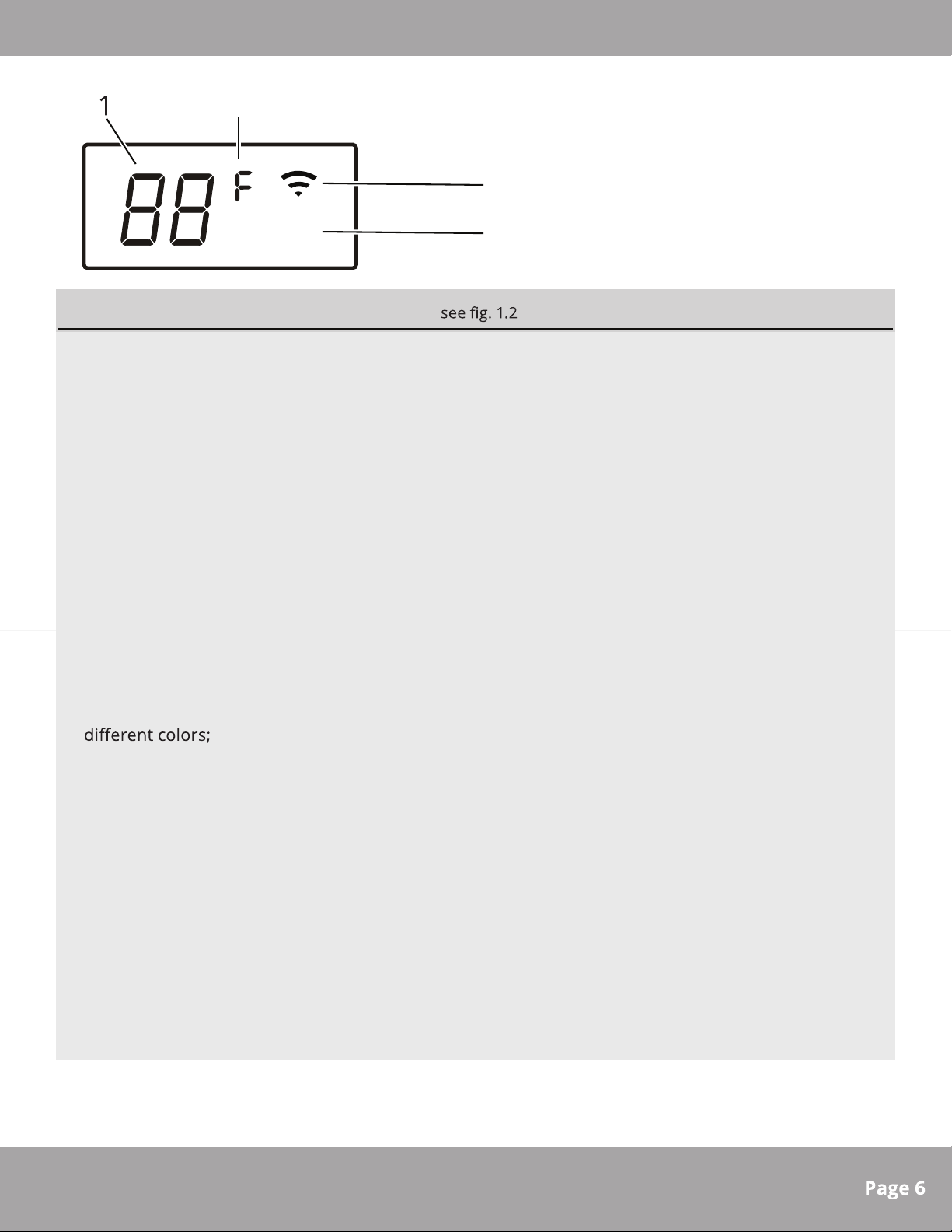
Overview - Display
°
ECO
3
4
Fig. 1.2
Display (on front panel of indoor unit)
1. Digital Display:
Displays the Temperature Setting when the air conditioner is operational.
Displays the Room Temperature when in FAN mode.
Displays the self-diagnostic codes.
Displays “ ON” for three seconds when the Timer is ON and/or Fresh, Swing, Turbo, or Silence
feature is activated.
Displays “ OF” for three seconds when the Timer is switched OFF .
Displays “ OF” for three seconds when the Fresh, Swing, Turbo, or Silence feature is canceled.
Displays “ dF” when Defrosting operation is active.
Displays “ cF” w
Displays “ SC” during Self Clean operation (if feature is available).
Displays “ FP” when Freeze Protection is active, operating under 46.4 °F (8 °C) (if feature is
2. Units of Measurement:
hen Anti-Cold Air feature is active in HEAT mode (when air temp is low).
available).
Displays “ °C” for Celsius or, “ °F” for Fahrenheit. Default units are “
switched by simultaneously pressing and holding both the up and down buttons on the remote
control.
According to the operation mode (heat/cool, etc.), the Units of Measureme
· Under Cool or Dry mode, it always displays as cool colors (Blue).
· Under Heat mode, it always displays as a warm color (Red).
3. Wireless Mode:
Displays when the wireless control feature is activated.
NOTE: A guide for using the infrared remote can be found in the “Remote Control User Manual”
which is included in this literature package.
4. Energy Saving Mode:
Displays when Energy Saving Feature is active. Not available on units not equipped with this feature.
” (Fahrenheit) and can be
°F
nt will display in
mrcool.com
Page 8
Accessories
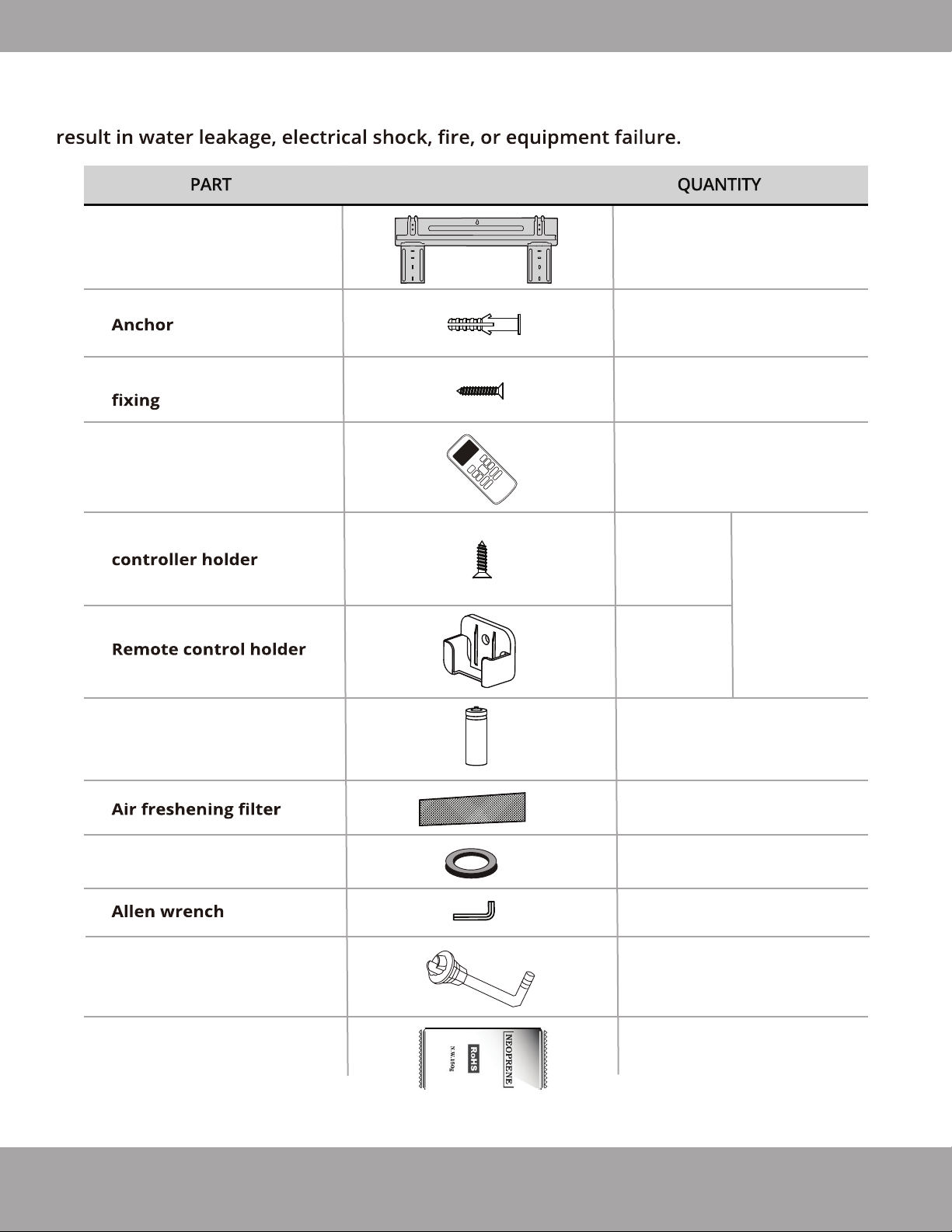
The air conditioning system includes the following accessories. Use all of the
installation parts and accessories to install the air conditioner. Improper installation may
LOOKS LIKE...
Mounting plate
Mounting plate
screw
Remote control
Fixing screw for remote
ST2.9 x 10
1
5
5
1
2
Optional
Parts
1
Dry battery AAA.LR03
Seal
Drain joint
Neoprene
Note: Illustrations are for explanatory purposes only - The actual shape and size may vary.
2
1
1
1
1
(Only for use
when elevated)
1
(Sealant for Wall Sleeve)
Page 7
mrcool.com
Page 9
Installation & Owner’s
Manual
Remote Control
Manual
Accessories
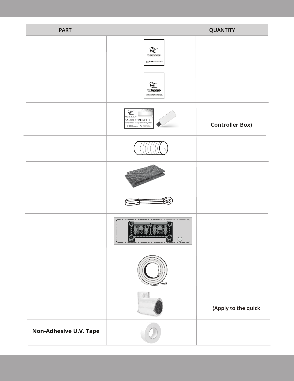
LOOKS LIKE...
Please read this manual carefully before installation and keep it for future reference.
Owner’s Manual
E-Star™ DIY Series
For more details visit www.MrCool.com
Please read this manual carefully before installation and keep it for future reference.
Remote Control
User Manual
For more details visit www.MrCool.com
1
1
Smart Controller Kit
Plastic Wall Sleeve
Sound deadening
pads
Drain Pipe
Cardboard
Mounting Plate
Template
1
(w/ Manual in
1
2
1
16 ft (5 m)
1
Quick Connect®
Line Set (refrigerant pipe)
Insulation material
1
2
connectors of the pipe)
1
Page 8mrcool.com
Page 10
Safety Precautions
Operating Instructions
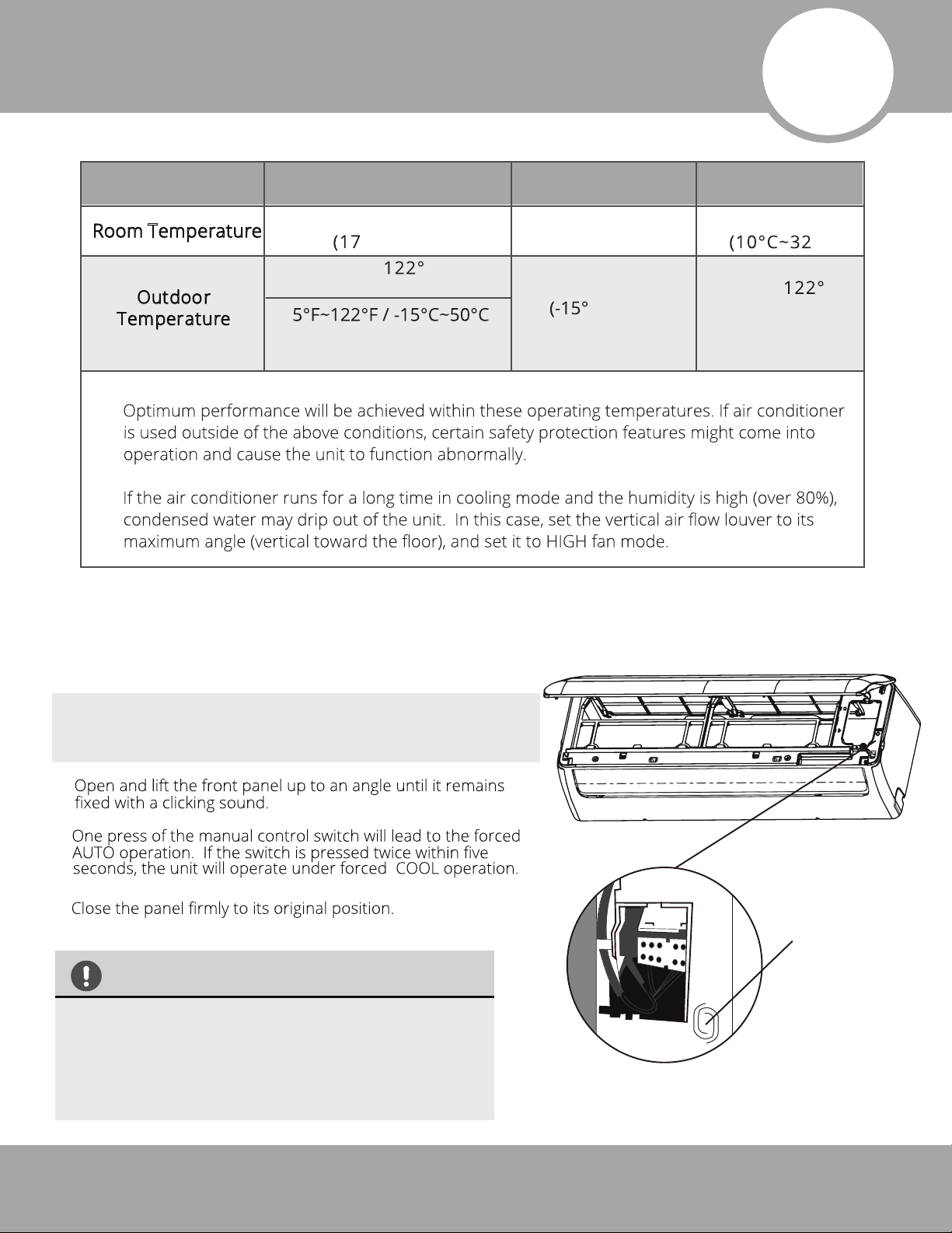
Cooling Operation Heating Operation Drying Operation
2
Room Temperature
utdoor
O
Temperature
NOTE:
1.
2.
Manual Operation
Units are equipped with a button to run emergency operation mode. This button is used for manual
operation in case the remote control fails, or maintenance is necessary. This can be accessed by
opening the front panel.
63°F~90°F
°C~32°C)
32°F~
(0°C~50°C)
(For the models with low
ambient cooling system)
F
32°F~86°F
(0°C~30°C)
5°F~75°F
C~24°C)
50°F~90°F
F~
32°
(0°C~50°C)
°C)
F
NOTE: The unit must be turned off before operating the
manual control button. If the unit is operational, continue
pressing the manual control button until the unit is off.
1.
2.
3.
CAUTION
• This button is used for testing purposes only.
Please do not use it unless necessary.
•To restore the remote control operation,
use the remote control directly.
Manual
Control
Button
(Forced cooling)
Fig 2.1
Page 9
mrcool.com
Page 11
Operating Instructions
·
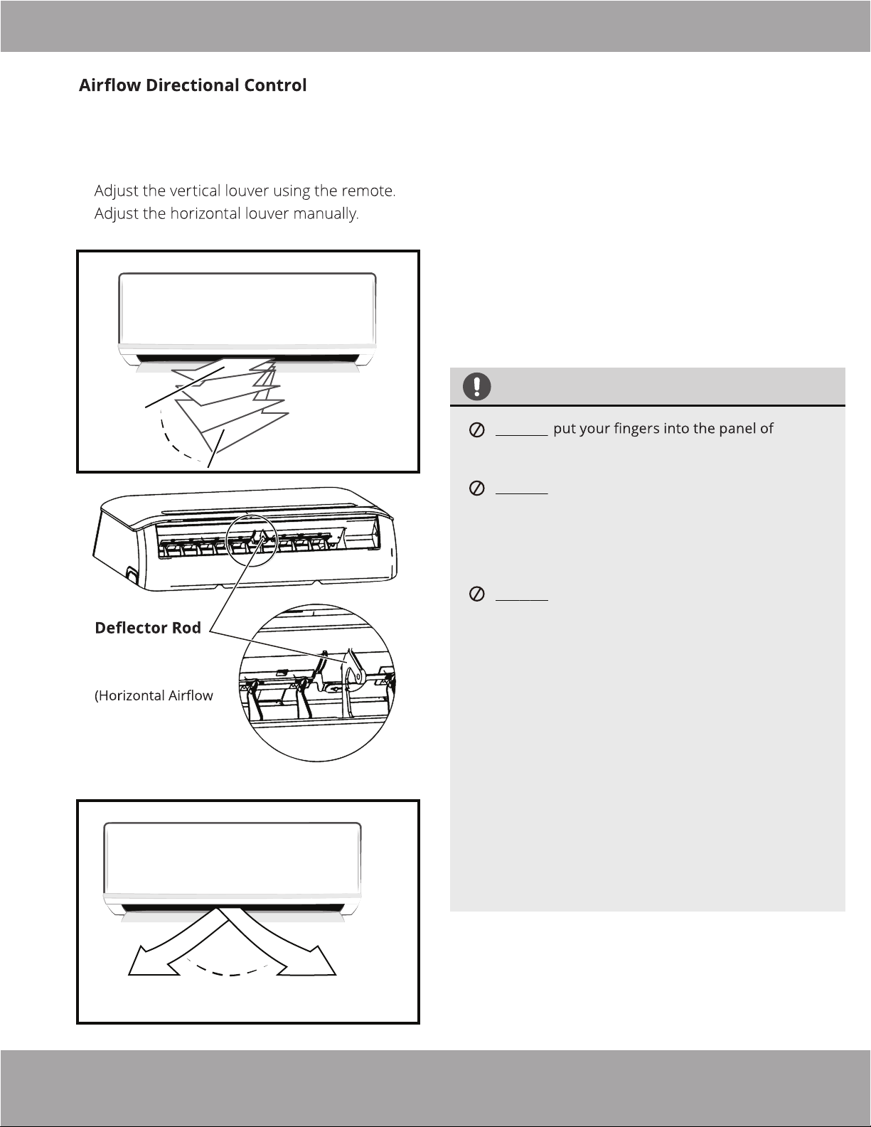
Adjustment of the vertical and horizontal
louvers will change airflow direction of
the indoor unit to prevent discomfort
and/or uneven room temperatures.
·
·
Adjust Vertical Airflow (Up/Down) using Vertical
Louver (Fig 2.2):
This function is performed by using the remote control,
while the unit is operating. The Vertical louver can move
in small increments for each press, or continuously
swing up and down automatically. Please refer to the
“Remote Control User Manual” for further details.
Adjust Horizontal Airflow (Left/Right) using
Horizontal Louver (Fig 2.3 & Fig 2.4)
Move the deflector rod, located on the underside of the
unit, by pushing the tab to manually adjust the airflow
from side to side as desired.
Range
Horizontal Louver
Grill inside)
Fig. 2.3
Vertical
Louver
Fig. 2.2
CAUTION
DO NOT
the blower and suction side. The high speed fan
inside may cause injury.
DO NOT operate the unit for long periods of time
in cooling or dehumidifying mode with the airflow
direction set downward. This could cause
condensation to form on the surface of the vertical
louver and allow moisture to drop onto furnishings
or the floor.
DO NOT
cause it to become out of sync. If this occurs, follow
these steps:
1. Turn off power to the unit
2. Remove wireless module from back of front
3. Turn off power to the circuit at the breaker
4. Wait a few seconds and turn the power back on
5. Reinstall wireless module into front cover
6. Turn the power to the unit back on
NOTE: After a quick restart, the vertical louver may
remain static for approximately 10 seconds.
move the vertical louver manually, as this
cover
at the breaker
Range
Horizontal
Louver
Fig. 2.4
mrcool.com
NOTE: Open angle of the vertical louver should not
be set too small, as it will restrict airflow and reduce
COOLING and HEATING performance of the unit.
Page 10
Page 12
Operating Instructions
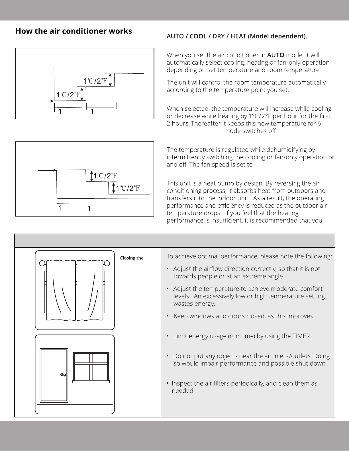
SLEEP operation
Set
Temperature
hour
hour
SLEEP Operation While Cooling
SLEEP operation
Set
Temperature
8 hours
timer OFF
8 hours
timer OFF
Basic Operation Modes:
Auto Operation:
SLEEP Operation:
hours before SLEEP
DRYING Operation:
LOW .
HEATING Operation:
hour
hour
SLEEP Operation While Heating
Optimal Operation
curtains while
heating also
helps keep the
heat in
Doors and
windows should
be kept closed
supplement heating with other appliances.
·
·
·
performance.
·
function.
·
the unit.
Page 11
·
mrcool.com
Page 13
Operating Instructions
Special Functions
Refrigerant Leakage Detection (optional):
Louver Angle Memory Function (optional):
Anti-Mildew Function (optional):
When the unit is turned off, in COOL, DRY, or AUTO (cool) modes, it will continue to run for about 10
minutes with low fan airflow. This is to aid in drying any condensation that has formed inside the unit to
prevent mildew growth. Do not restart the air conditioner until the unit is completely off.
Optimal Operation:
Wireless Smart Control Function:
Clean Air Filter Reminder (optional):
Replace Air Filter Reminder (optional):
Mute Function (optional):
Press the LED LED
LED button on
LED button
mrcool.com
Page 12
Page 14
Operating Instructions
Care and Maintenance
CAUTION
3
Power supply must be disconnected before attempting
any kind of cleaning or service. Before performing
maintenance, turn the power off to the unit and then
disconnect the power to the circuit at the breaker.
Failure to do this could cause electrical shock.
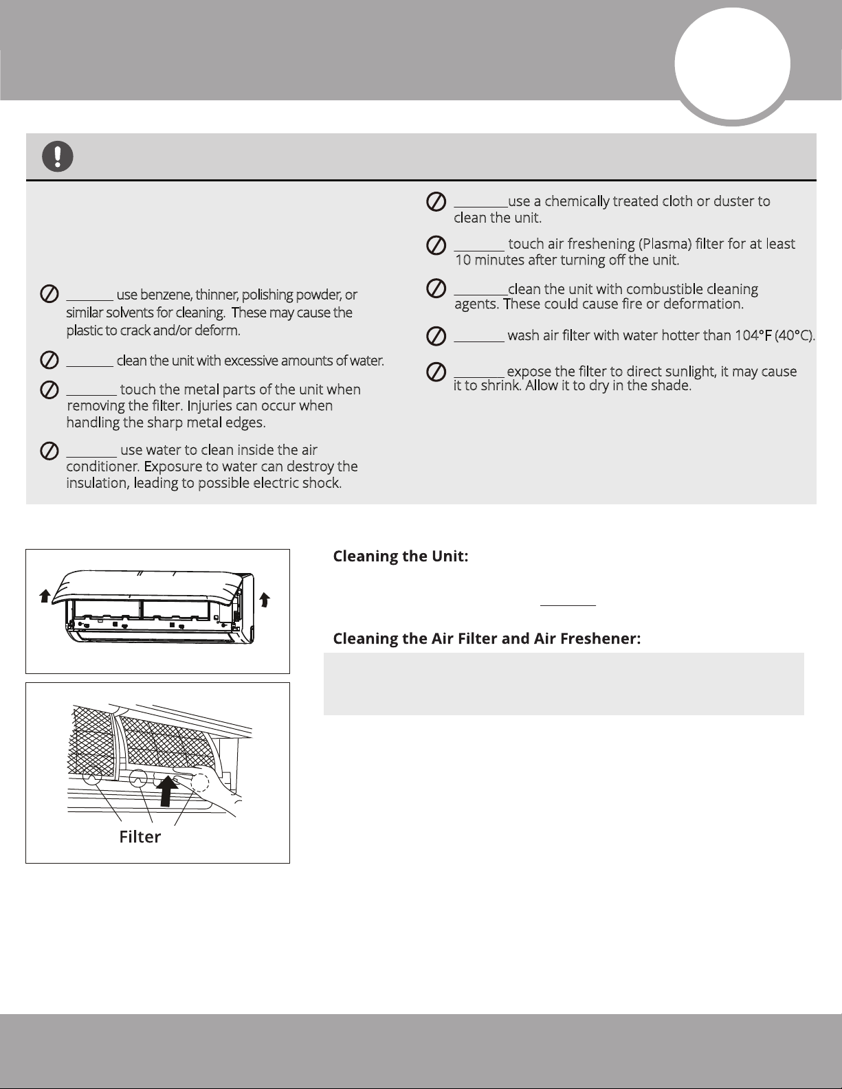
DO NOT use benzene, thinner, polishing powder, or
similar solvents for cleaning. These may cause the
plastic to crack and/or deform.
DO NOT clean the unit with excessive amounts of water.
DO NOT touch the metal parts of the unit when
removing the filter. Injuries can occur when
handling the sharp metal edges.
DO NOT
conditioner. Exposure to water can destroy the
insulation, leading to possible electric shock.
use water to clean inside the air
1
Wipe the unit with a soft dry cloth. If the unit is very dirty, wipe it with
a cloth soaked in warm water. DO NOT use bleach or abrasives.
DO NOT use a chemically treated cloth or duster to
clean the unit.
touch air freshening (Plasma) filter for at least
DO NOT
10 minutes after turning off the unit.
DO NOT clean the unit with combustible cleaning
agents. These could cause fire or deformation.
DO NOT
DO NOT
it to shrink. Allow it to dry in the shade.
wash air filter with water hotter than 104°F (40°C).
expose the filter to direct sunlight, it may cause
2
Page 13
Tab
NOTE: A clogged air filter can greatly reduce heating and
cooling efficiency of this unit. It is recommended to clean the
unit every 2 weeks.
Open the front by carefully lifting both ends at the same time.
1.
As you continue lifting, at a certain angle there will be an audible
click and the lid will become self-supporting. Some models are
equipped with suspension bars that are required to prop the lid
open.
2.
Use the filter tabs to lift filter slightly upward and then pull it
towards you.
mrcool.com
Page 15
Care and Maintenance
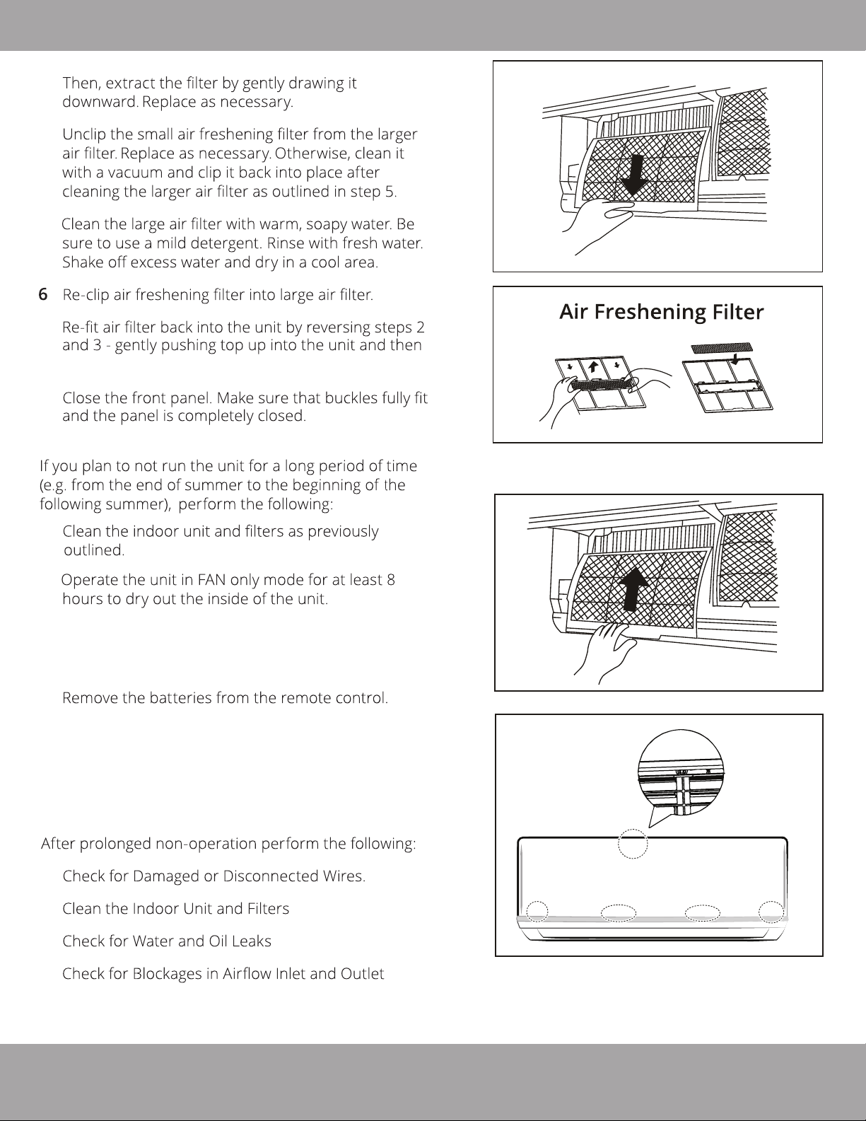
3.
4.
5.
.
7.
lowering the bottom into place.
8.
Preparation for Extended non-Operation:
3
4
Removal
Install
1.
2.
Turn off the unit. Then, turn off the power to the
3.
circuit at the breaker. The unit should be the only
appliance on this circuit.
4.
The outdoor unit also requires periodic maintenance.
5.
However, it is highly recommended you contact a
qualified service professional to perform this. Please do
not attempt to do this on your own.
Pre-Season Inspection:
1.
2.
5
6
Panel buckles
3.
4.
Replace Batteries in Remote Control
5.
mrcool.com
Page 14
Page 16
Installation Summary - Indoor Unit
Indoor Unit Installation
4
Installation Instructions
– Indoor Unit
PRIOR TO INSTALLATION:
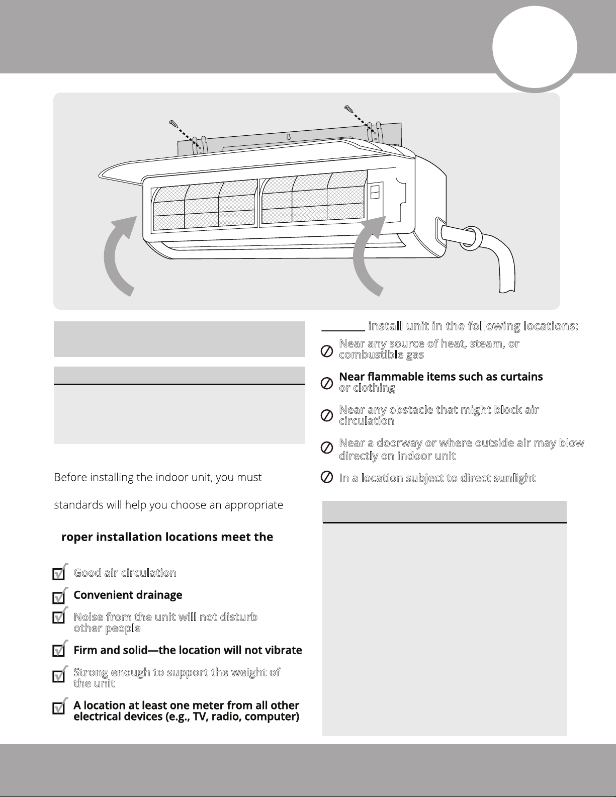
Before installing the indoor unit, refer to the
label on the product box to make sure that
the model numbers of the indoor unit and
the outdoor unit match.
Step 1: Selecting an installation location
choose an appropriate location. The following
location for the unit.
P
following standards:
Good air circulation
Noise from the unit will not disturb
other people
Strong enough to support the weight of
the unit
DO NOT install unit in the following locations:
Near any source of heat, steam, or
combustible gas
or clothing
Near any obstacle that might block air
circulation
Near a doorway or where outside air may blow
directly on indoor unit
In a location subject to direct sunlight
NOTE ABOUT WALL HOLE:
If there is no fixed refrigerant piping:
While choosing a location, be sure that
you leave ample room for a wall hole
(see the Drill Wall Hole for Connective
Piping step on the following pages) for
the signal cable and refrigerant piping,
which connect the indoor and outdoor
units. The default position for all piping
is the right-hand side of the indoor unit
(while facing the front of the unit). After
the piping and signal wire are installed,
use the provided neoprene (spray foam
can be used instead, if you prefer) to
pack the space left in hole, in order to
seal it and make it airtight.
Page 15
mrcool.com
Page 17
Indoor Unit Installation
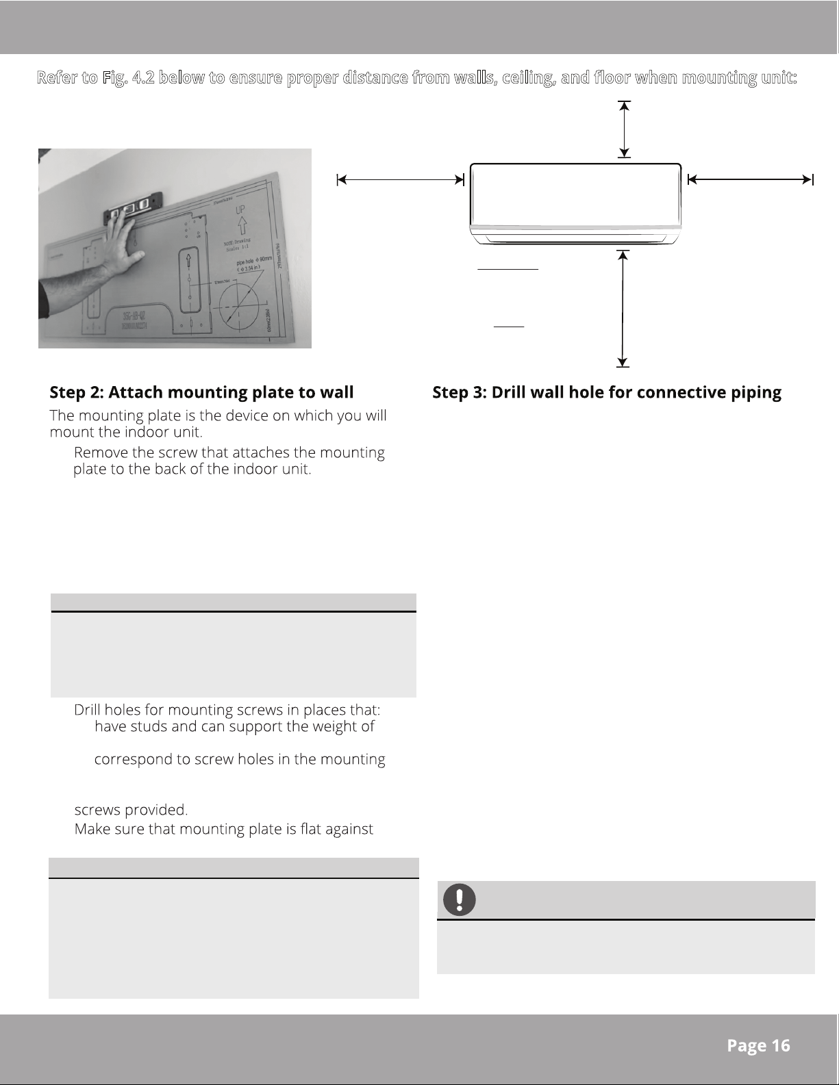
Refer to Fig. 4.2 below to ensure proper distance from walls, ceiling, and floor when mounting unit:
Minimum Ceiling
Clearance
5.9 in (15 cm)
Minimum Side
Clearance
4.75 in (12 cm)
Fig. 4.1
1.
Place the mounting plate against the wall in
2.
a location meets the guidelines in the
Selecting an Installation Location step.
Refer to the Mounting Plate Dimensions
section for detailed information on
mounting plate sizes.
NOTE
A cardboard template of the mounting plate is included
to be used as a more manageable way of determining
where to mount the mounting plate and drill the wall
hole. It can be placed against the wall in place of the
actual mounting plate for the previous step (See Fig 4.1).
3.
•
the unit
•
plate
4. Secure the mounting plate to the wall with the
5.
the wall.
NOTE FOR CONCRETE OR BRICK WALLS:
*For Ceilings GREATER than 9 ft.,
recommended distance from floor
90.55 in (230 cm)
*For Ceilings LESS than 9 ft.,
recommended distance from floor
78.55 in (200 cm)
You must drill a hole in the wall for the refrigerant
piping, drainage pipe, and signal cable to pass
through in order to connect the indoor and outdoor
units.
Determine the location of the wall hole based on
1.
the position of the mounting plate. Refer to the
Mounting Plate Dimensions (See Fig 4.5) to
assist you in determining the optimal position for
the hole, based on the type of mounting plate
provided with your unit.
2.
Using a core drill, with a 3.54 in (90 mm)
diameter, drill a hole in the wall at a slight
downward angle, so that the indoor end of the
hole is higher than the outdoor end of the hole,
by approximately 0.2 in to 0.275 in (5 mm to 7
mm). This will ensure proper water drainage from
the indoor unit (See Fig. 4.3).
Insert the protective wall sleeve through the
3.
hole of the inside wall, noting the amount it
protrudes from the exterior wall. Then, trim the
excess, with a utility knife or a saw, to make it
flush with the exterior wall. This will protect the
edges of the hole and help seal it when you
finish the installation process (See Fig 4.4).
Minimum Side
Clearance
4.75 in (12 cm)
Fig. 4.2
If the wall is made of brick, concrete, or a similar
material, drill 0.2 in. diameter (5 mm diameter)
holes in the wall and insert the sleeve anchors
provided. Secure the mounting plate to the
wall by tightening the screws directly into the
anchors.
mrcool.com
CAUTION
When drilling the wall hole, be sure to avoid
wires, plumbing, nails, screws, and other
sensitive components.
Page 18
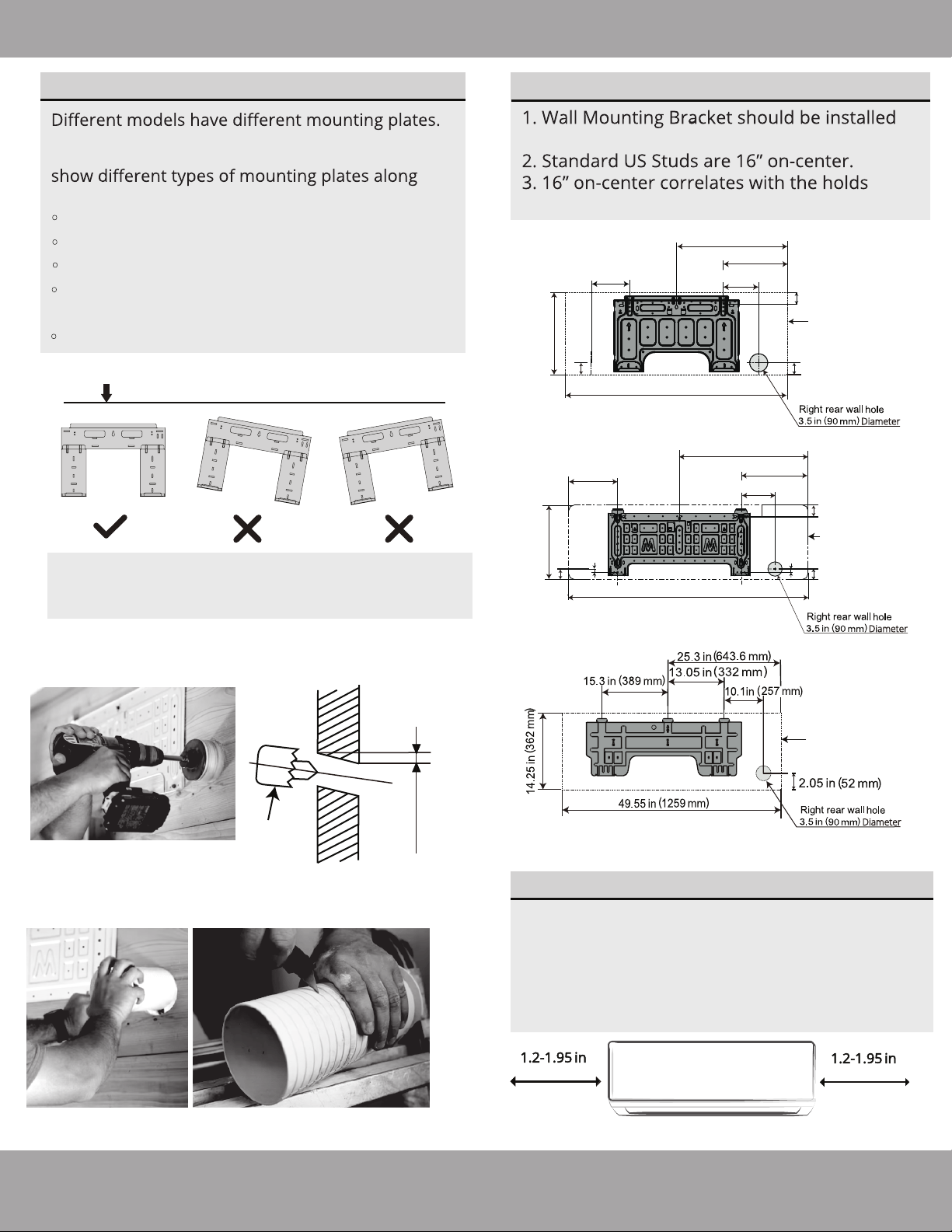
Indoor Unit Installation
MOUNTING PLATE DIMENSIONS
In order to ensure that you have ample room to
mount the indoor unit, the diagrams to the right
with the following dimensions:
•
Height & Width of mounting plate
Height & Width of indoor unit relative to plate
•
Recommended position of wall hole
•
Relative distances between screw/mounting
•
holes
Do not attempt a left rear wall hole.
•
Correct orientation of Mounting Plate
NOTE: Use a level in order to ensure your
mounting plate is mounted to the wall with
the correct orientation shown above.
Correct Angle to Drill Wall Hole
Indoor
Wall
Outdoor
NOTE REGARDING WALL STUDS
on studs.
marked “US” on the metal bracket.
16.8 in (426 mm)
7.55 in (192 mm)
1.7 in (43 mm)
11.7 in (297 mm)
31.6 in (802 mm)
9.15 in (232 mm)
5.05 in (128 mm)
Series 12K Models
21.77 in (553 mm)
8.6 in (219 mm)
0.6 in (15 mm)
1.7 in (43 mm)
13.2 in (335 mm)
42.5 in (1080 mm)
11.8 in (300 mm)
5.9 in (151 mm)
0.6 in (15 mm)
Series 18K & 24K Models
1.7 in
(43 mm)
Outline of indoor unit
when mounted to plate
1.7 in
(43 mm)
Diameter
2.1 in
(53.5 mm)
Outline of indoor unit
when mounted to plate
1.8 in
(47 mm)
Diameter
Drill used to
create wall
hole
Fig. 4.3
Wall Hole Sleeve Installation
Fig. 4.4
0.2 - 0.3in
(5 - 7 mm)
Outline of indoor unit
when mounted to plate
Series 36K Models
Diameter
Fig. 4.5
UNIT IS ADJUSTABLE
Keep in mind that the hooks on the mounting
plate are smaller than the holes on the back of
the unit. If you find that there is not enough room
to connect embedded pipes to the indoor unit, it
can be adjusted left or right by 1.25-1.95 in
(30-50 mm), depending on the model.
(30-50 mm)
Adjustment range of indoor unit to the left or right
(30-50 mm)
Page 17
mrcool.com
Page 19
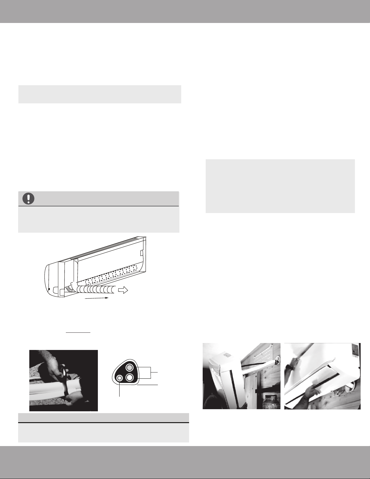
Indoor Unit Installation
Step 4: Prepare indoor unit refrigerant piping
The piping of the indoor unit is attached to the back of
the unit towards the bottom. It will be covered with
insulation, and there will also be a drain pipe with these.
This piping will need to be bent and prepared before
it can be fed through the wall hole.
NOTE: Refrigerant piping should exit the indoor
unit from the right-hand side (Refer to Fig 4.6)
1.
Based on the position of the wall hole, relative to
the mounting plate, determine the necessary angle
the piping will need to be bent to pass through the
wall hole when the unit is mounted to the bracket.
Grip the refrigerant piping at the base of the bend.
2.
Then, slowly, and with even pressure, bend the
piping away from the back of the unit roughly 90
degrees. The piping should be sticking straight out
from behind the unit once completed (Refer to
Fig 4.6).
CAUTION
Be extremely careful not to dent or damage the
piping while bending it away from the unit, as
this could negatively affect the performance.
Fig. 4.6
Step 5: Mount the Indoor Unit
In the following steps the indoor unit will now be
mounted to the wall bracket and the piping and
wires will be fed through the wall hole.
Double-check that the ends of the refrigerant
1.
pipes are sealed (screw on caps are still in
place) to prevent any dirt or foreign material
from entering the pipes.
Feed the signal wire (should be protected by
2.
conduit) through the wall hole.
Carefully lift the indoor air handler, and slowly
3.
feed the taped bundle of refrigerant pipes
and drain hose through the wall hole, as you
position it to mount to the wall bracket.
NOTE: Positioning the air handler on to the
wall bracket, while feeding the piping
through the wall hole, might be difficult for
a single person to manage. If so, it may be
necessary to seek the assistance of another
person for this step.
Slightly lean the top of the air handler toward
4.
the wall and hook the top of the indoor unit
on the upper hook of the wall mounting plate.
Check that the unit is hooked firmly on the
5.
mounting plate by applying slight pressure to
the left and right-hand sides of the unit. The
unit should not jiggle or shift.
Now, you will need to lightly tape the refrigerant
3.
piping and drain pipe together in a bundle, using
electrical tape, making sure that the drain pipe is at
the bottom. DO NOT tape the ends of the piping
(connectors). Refer to Fig 4.7 and the image below
for the correct orientation of the piping when taping.
Refrigerant
piping
Tape
Drain hose
Fig. 4.7
DRAIN HOSE MUST BE ON BOTTOM
The drain hose must be placed at the bottom of the
bundle. If it is not, it could cause the drain pan to
overflow, which could lead to fire or water damage.
Using even pressure, push down on the
6.
bottom half of the unit. Continue pushing
down until the unit snaps onto the hooks along
the bottom of the mounting plate.
Again, check that the unit is firmly mounted to
7.
the wall bracket by applying slight pressure to
the left and right-hand sides of the unit.
mrcool.com
Page 18
Page 20
Indoor Unit Installation
Outdoor Unit Installation
5
Installation Instructions –
Outdoor Unit
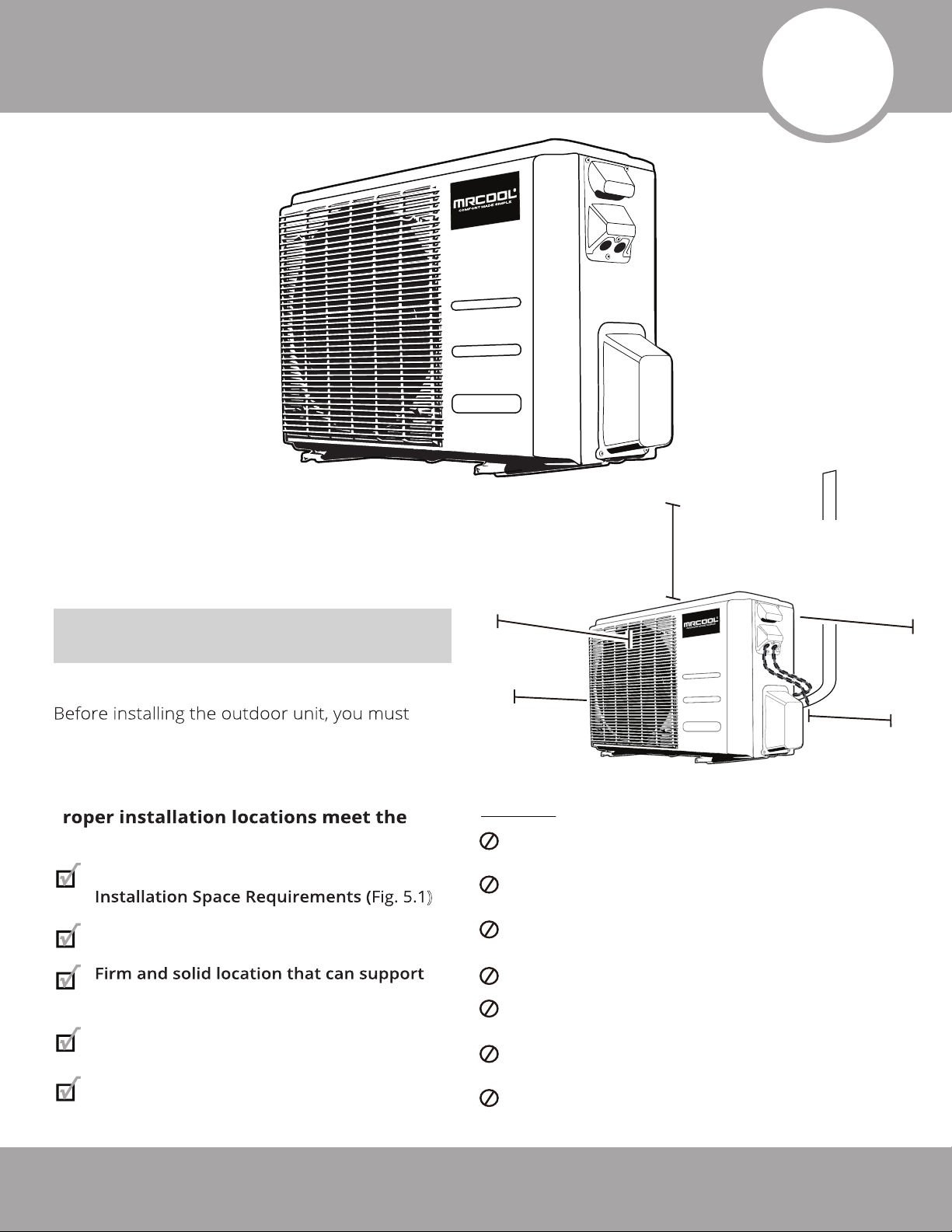
Step 1: Selecting an installation location
choose an appropriate location. Use the following
guidelines to help you select an appropriate
location.
P
following guidelines:
Meets all spatial requirements shown in
Good air circulation and ventilation
Minimum clearance
on the left side
of unit: 12 in (30cm)
DO NOT
)
Minimum Clearance
above unit:
Minimum clearance
in front of unit:
79in (200cm)
79 in (200cm)
in front
12in (30cm)
on left
24in (60cm)
above
24 in (60cm)
Minimum Clearance
between back of the unit
and wall:
**Ground Installed:
12 in (30 cm)
**Bracket Installed:
Minimum Clearance
24in (60cm)
on the right side
on right
of the unit: 24 in (60cm)
install unit in the following locations:
Near an obstacle that will block air inlets and
outlets
Near a public street, crowded areas, or where
noise from the unit will disturb others
Near animals or plants that will be harmed
by hot air discharge
6 in (15 cm)
Fig. 5.1
the unit and will not cause vibration
Noise from the unit will not disturb others
Protected from prolonged periods of
exposure to direct sunlight or rain
Page 19
Near any source of combustible gas
In a location that is exposed to large amounts
of dust
In a location exposed to a excessive
amounts of salty air
In a location that exposes the unit to large
amounts of forced water
mrcool.com
Page 21
Outdoor Unit Installation
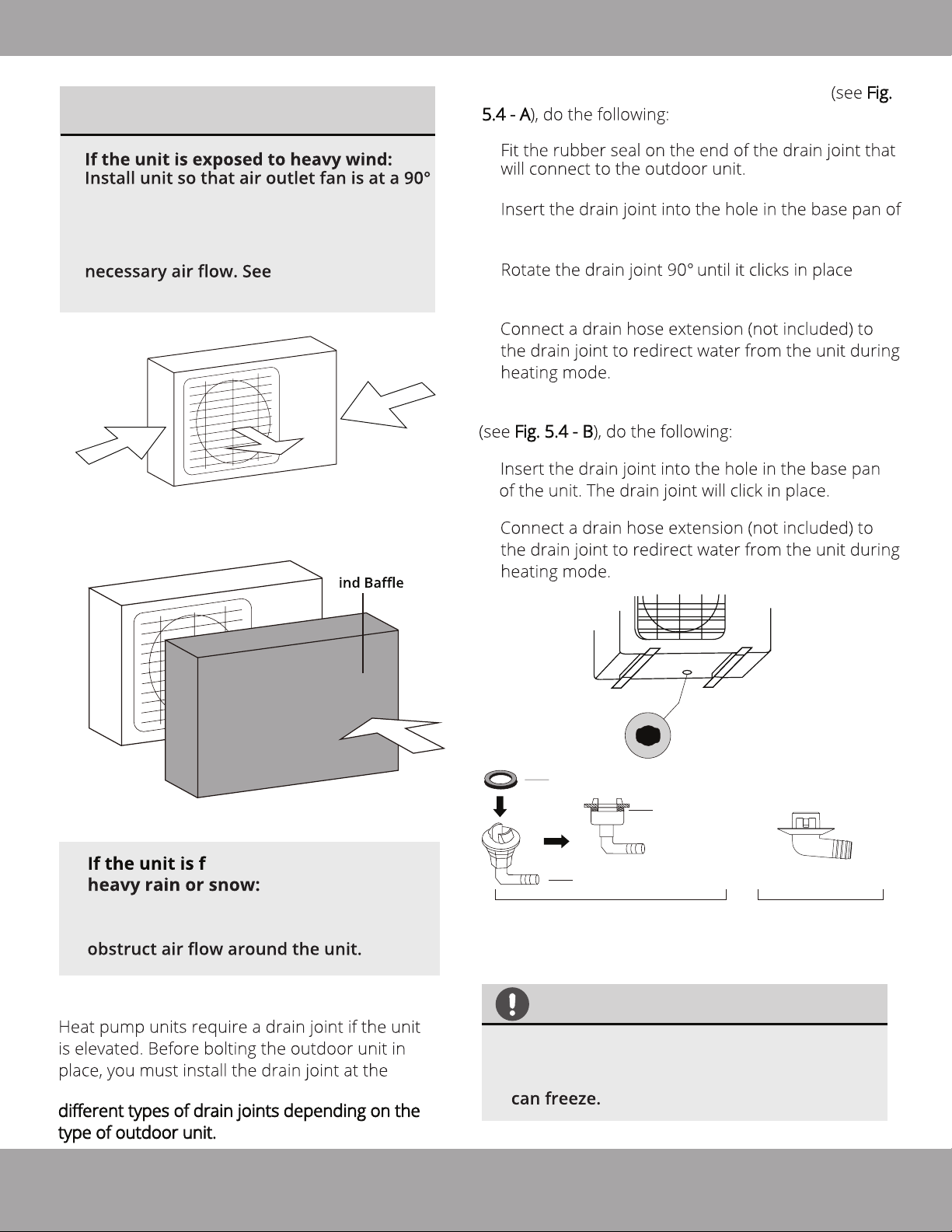
SPECIAL CONSIDERATIONS FOR
EXTREME WEATHER
angle to the direction of the wind. If
needed, build a barrier in front of the unit
to protect it from extremely heavy winds.
Ensure the wind barrier does not block
Fig. 5.2 and
Fig. 5.3 below.
Strong wind
Strong wind
Fig. 5.2
If the drain joint comes with a rubber seal Fig.
1.
2.
the unit.
3.
facing the front of the unit.
4.
If the drain joint does not come with a rubber seal
1.
2.
W
Fig. 5.3
requently exposed to
Build a shelter above the unit to protect
it from the rain or snow. Be careful not to
Step 2: Install drain joint
Strong wind
Base pan hole of
outdoor unit
Seal
Seal
Drain joint (only use if elevated)
(A) (B)
Fig. 5.4
DRAINAGE IN COLD CLIMATES
bottom of the unit. NOTE: there are two
In cold climates, make sure that the drain
hose is as vertical as possible to ensure swift
water drainage. If water drains too slowly, it
mrcool.com
Page 20
Page 22
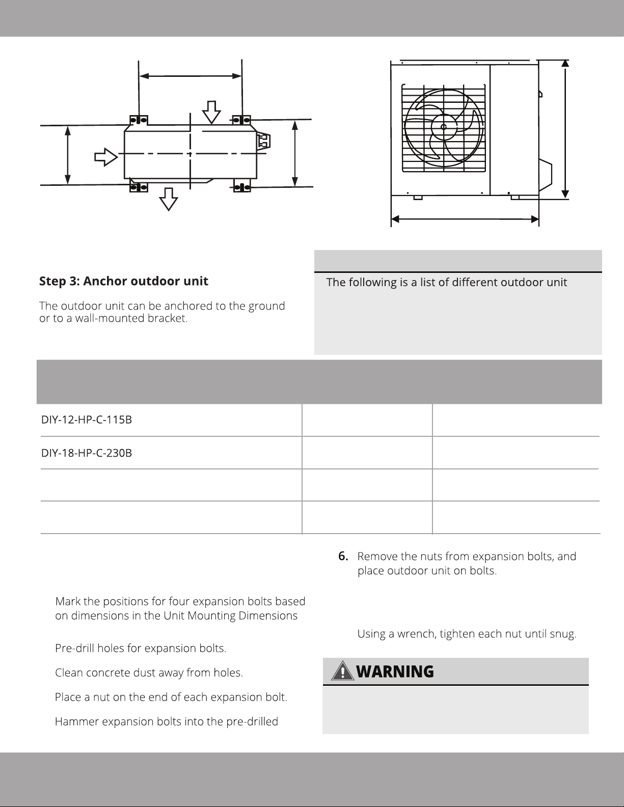
Outdoor Unit Installation
TOP VIEW
Air Inlet
D
A
Air Inlet
Air Outlet
FRONT VIEW
H
B
W
Fig. 5.5
UNIT MOUNTING DIMENSIONS
sizes and the distance between their mounting feet.
Prepare the installation base of the unit according
to the dimensions in the table below, using the
illustrations of the unit above (Fig 5.5) as a
reference/guide to correspond with the table.
Outdoor Unit Dimensions:
Inches (Millimeters)
Width (W) x Height (H) x Depth (D)
31.5 in x 21.8 in x 13.1 in
(800 mm x 554 mm x 333 mm)
33.25 in x 27.63 in x 14.29 in
(845 mm x 702 mm x 363 mm)
DIY-24-HP-C-230B
DIY-36-HP-C-230B
If you are installing the outdoor unit on the
ground, or a concrete mounting platform, use the
following steps:
1.
chart and illustrations above.
2.
37.21 in x 31.90 in x 16.53 in
(946 mm x 810 mm x 420 mm)
37.21 in x 31.90 in x 16.53 in
(946 mm x 810 mm x 420 mm)
Mounting Dimensions:
Inches (Millimeters)
Width (A)
20.24 in
(514 mm)
21.26 in
(540 mm)
26.5 in
(673 mm)
26.5 in
(673 mm)
7.
Put a washer on each of the expansion bolts,
then reinstall the the nuts.
8.
Depth (B)
13.39 in
(340 mm)
13.80 in
(350 mm)
15.87 in
(403 mm)
15.87 in
(403 mm)
3.
4.
5.
holes.
Page 21
WHEN DRILLING INTO CONCRETE,
EYE PROTECTION IS RECOMMENDED
AT ALL TIMES.
mrcool.com
Page 23
Outdoor Unit Installation
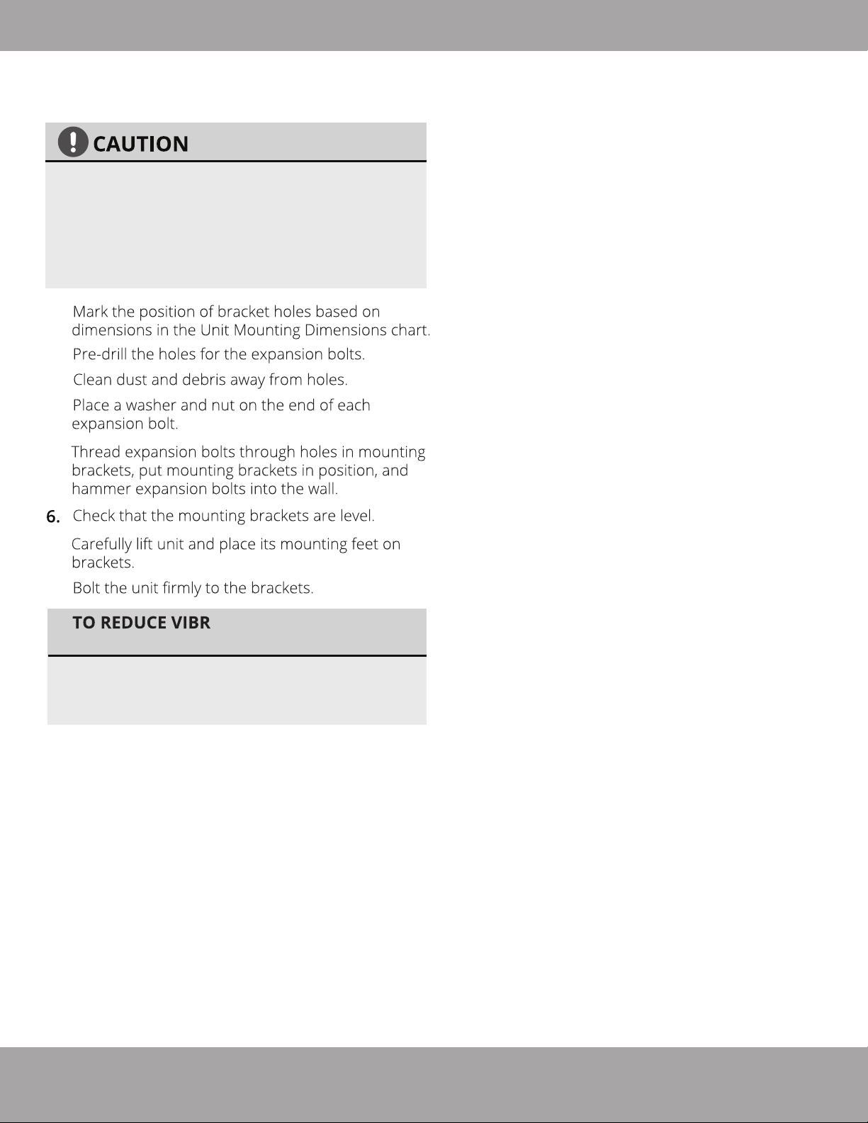
If you are installing the unit on a wall-mounted
bracket, follow these steps:
Before installing a wall-mounted unit,
make sure that the wall is made of solid
brick, concrete, or a similarly strong
material.
support at least 4 times the weight
of the unit.
1.
2.
3.
4.
The wall must be able to
5.
7.
8.
ATION OF WALL-
MOUNTED UNIT
If allowed, you can install the wall-mounted
unit with rubber gaskets to reduce vibration
and noise.
the
mrcool.com
Page 22
Page 24
Refrigerant Piping Connection
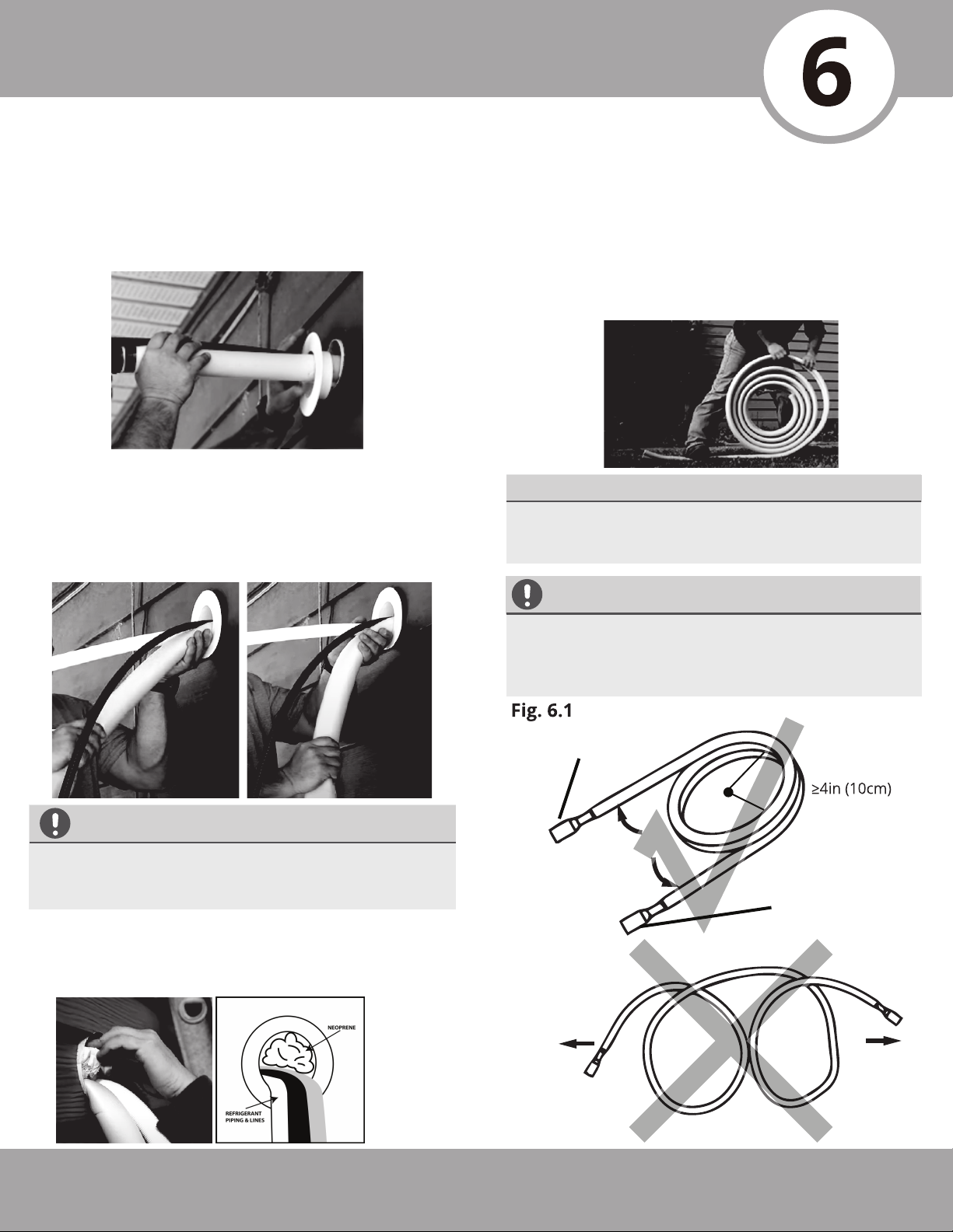
Step 1: Prepare exterior wall hole
Before the refrigerant piping can be installed and
connected to the indoor and outdoor units, some
additional steps are required to prepare the exterior.
Install finishing ring/cap to exterior portion of the
1.
wall hole.
Place your hand on the underside of the piping
2.
coming through the exterior wall hole (from
indoor unit), close to the wall. With your other
hand, using even pressure, carefully bend the
piping downward toward the wall, being mindful
not to damage or dent the piping in the process.
Step 2: Unwind Quick Connect® Line Set to
necessary length
Use your hands to slowly unwind the copper piping
1.
of one end of the Quick Connect® Line Set. The end
you unwind will connect to the indoor unit piping.
Only unwind as much as necessary for your
application, and allow any excess to remain coiled
(Refer to Fig. 6.1).
MINIMUM BEND RADIUS
When bending connective refrigerant piping, it
needs to have a minimum bend radius of 4 inches
(Refer to Fig 6.1).
CAUTION
CAUTION
Be extremely careful not to dent or damage the
piping while bending it down the exterior wall, as
this could negatively affect the performance.
Pack the wall hole with the supplied Neoprene
3.
(or Spray Foam can be used) to seal the hole,
filling any space that was not taken up by the
refrigerant piping and lines.
If the pipe is repeatedly bent or extended, it will
become hard and difficult to manipulate. Avoid
bending or extending the pipe more than 3 times,
or excessively, as it could break.
Carefully unroll to indoor
handler connection
Radius
Keep excess coiled
Connect directly to
exterior condensor
Page 23
mrcool.com
Page 25
Refrigerant Piping Connection
Step 3: Connect Line Set to Indoor Unit
3.1 Tools needed
NOTE: Depending on the capacity rating of your unit,
(12K, 18K, 24K, 36K) the wrench sizes needed will vary, refer
to the table below (the unit uses metric sizes, the standard
sizes listed are approximations). Based on the availability of
wrenches in some of the sizes needed, the recommended
method is to use crescent (adjustable-type) wrenches that
can be adjusted to fit the size each step requires.
.
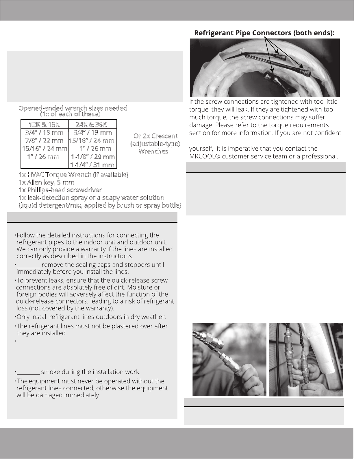
Opened-ended wrench sizes needed
(1x of each of these)
12K & 18K 24K & 36K
3/4” / 19 mm 3/4“ / 19 mm
7/8” / 22 mm 15/16“ / 24 mm
15/16” / 24 mm 1“ / 26 mm
1” / 26 mm 1-1/8” / 29 mm
1-1/4” / 31 mm
.
1x HVAC Torque Wrench (if available)
.
1x Allen key, 5 mm
.
1x Phillips-head screwdriver
.
1x leak-detection spray or a soapy water solution
(liquid detergent/mix, applied by brush or spray bottle)
3.2 IMPORTANT INFORMATION
PLEASE READ FULLY BEFORE PROCEEDING TO NEXT STEP
DO NOT
Or 2x Crescent
(adjustable-type)
Wrenches
}
about connecting the refrigerant line connectors
IMPORTANT:
The line sets are designed to only be installed once.
The seal within the line set cannot be guaranteed if
they are installed more than once. This will void the
warranty. They also contain a compression fitting
to seal and do not require a thread sealent (teflon
tape, etc.). Using a sealent may actually cause the
connection to leak over time.
3.3 Connecting the Quick Connect® Line Set
to the piping from indoor unit
Do not remove the plastic seals of the piping coming
1.
from the indoor unit, or the appropriate line set
connector, until immediately before you connect
them. The plastic seals on each of the connectors
should be color-coded to match the seals of the
corresponding pipes they are to be connected to.
Align the refrigerant pipes correctly, making sure
2.
the dimensions of the connecting refrigerant pipe
match. Unscrew the seals and place the screw
connector of the line set pipe just onto the
threads of the piping from the indoor unit, and
tighten the first few threads by hand.
Always wear work gloves and goggles and use caution
when handling refrigerant. Please make sure that
refrigerant is never allowed to enter the environment.
Improper handling of refrigerant may be harmful to
your health.
DO NOT
•
The screw connections may only be tightened using
the appropriate open-ended or crescent (adjustable-type) wrench.
mrcool.com
IMPORTANT:
Before you continue, it is essential that you read
the following instructions fully and carefully.
Page 24
Page 26
Refrigerant Piping Connection
TORQUE REQUIREMENTS
1.
2.
3.
NOTE: Torque ratings in the table below are to be used if you have access to an HVAC torque wrench. These are
available for purchase from online retailers. However, it is possible to complete installation of refrigerant line
sets with conventional open-ended/crescent wrenches. It is imperative, however, that you not overtighten the
connector, and that once the lines have been fully connected, you follow the steps to check for leaks. If you do
not feel comfortable attempting this, please contact a qualified HVAC technician.
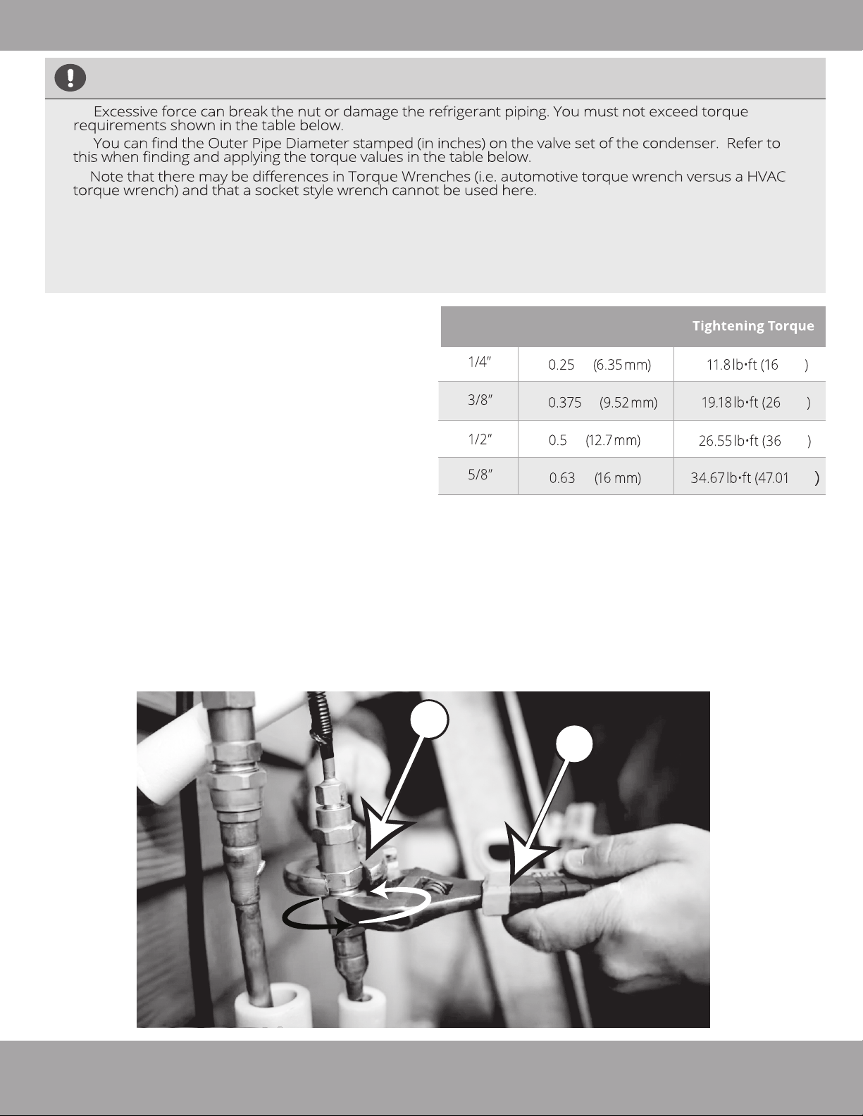
Using the image below as a guide, and the steps
3.
outlined in this paragraph, you will now tighten the
nuts of the screw connectors of the Quick
Connect® Line Set to the indoor unit. Using two
appropriate sized open-ended wrenches
(depending on the dimensions of the connector) or
adjustable crescent wrenches, place one of the
wrenches on the nut marked “1”, and the other
wrench on the nut marked “2,” as shown in the
image below. Now, turn the wrench marked “2” in
the direction of the rotational arrows, as shown,
while holding the other wrench in place. Continue
to tighten the connector until snug. NOTE: work
quickly and make sure the screw connectors do
not become crooked as you tighten them.
*If an HVAC torque wrench is available: Once the
connector is snug, using the torque wrench, tighten
the connector to the specified torque rating, listed in
the table above (based on the pipe size).
*If an HVAC torque wrench is NOT available:
Using the two wrenches you used to tighten the
connector, once the connector is snug, turn the
wrench slightly beyond that point to torque the
connector, but do not overtighten it.
Repeat the same process for the second line.
4.
Stamp
Outer Pipe
Diameter
inch (millimeter)
in
in
in
in
Maximum
lb·ft (N·m)
N·m
N·m
N·m
N·m
Page 25
1
2
mrcool.com
Page 27
Refrigerant Piping Connection
CAUTION
Step 4: Connect Line Set to the Outdoor Unit
1.
shown in the illustration.
Do not remove the plastic seals from the
2.
outdoor unit piping connectors and
corresponding refrigerant pipes (line set
to be attached) until immediately before
you connect them.
IMPORTANT:
Before you continue, it is essential that you read
the following instructions carefully.
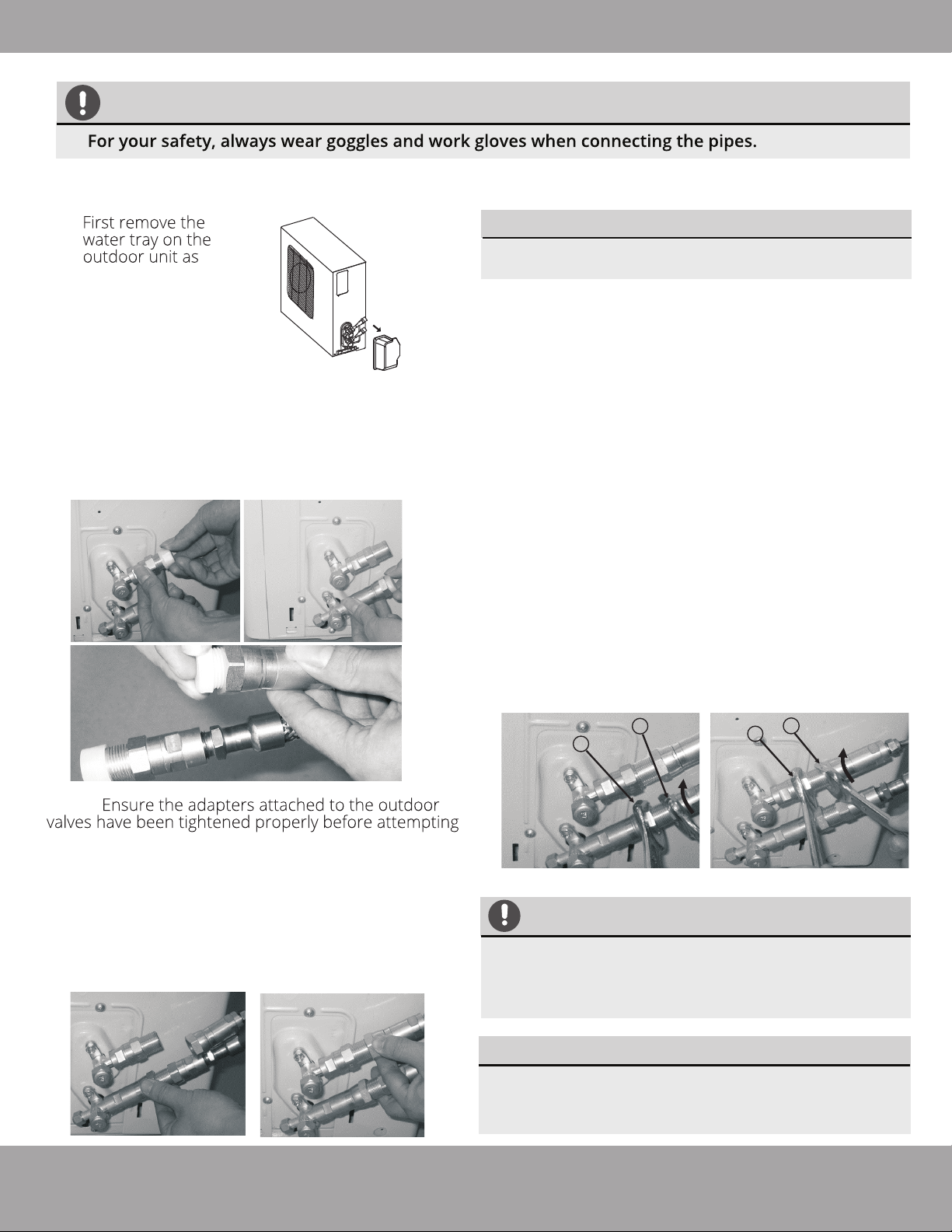
Using the first image below as a guide, starting with
4.
the bottom screw connector, you will now tighten the
line set to the outdoor unit. Using two appropriate
sized open-ended wrenches (depending on the
dimensions of the connector), or adjustable crescent
wrenches, place one of the wrenches on the nut
marked “1”, and the other wrench on the nut marked
“2,” Now, turn the wrench on nut “2” in the direction of
the rotational arrow, while holding the other wrench in
place, as seen in the first image below. Continue to
tighten the connector until snug. NOTE: work quickly
and make sure the screw connectors do not
become crooked as you tighten them.
*If an HVAC torque wrench is available: Once the
connector is snug, using the torque wrench, tighten
the connector to the specified torque rating, listed in
the table on the next page (based on the pipe size).
*If an HVAC torque wrench is NOT available:
Using the two wrenches you used to tighten the
connector, once the connector is snug, then turn the
wrench slightly beyond that point to torque the
connector, but do not overtighten it.
5.
Repeat the same process for the top screw connector,
using the second image below as a guide.
NOTE:
to connect the line set.
Align the refrigerant pipes so they line up with
3.
the corresponding valves and have enough
slack. NOTE: The refrigerant pipes must be
connected to the valves with as little stress
as possible. Unscrew the plastic seals and
place the screw connector of the refrigerant
line just onto the threads of the outdoor unit,
tightening the first few threads by hand.
2
1
2
1
IMPORTANT
The coupling of the outdoor unit uses tapping
rings, if you disconnect and reconnect the
refrigerant pipes, it could cause it to leak. This will
also void the warranty.
NOTE:
Keep excess refrigerant hose coiled. Wrap with
protective tape and store behind the condenser in
a horizontal position (flat with the ground).
mrcool.com
Page 26
Page 28

Refrigerant Piping Connection
TORQUE REQUIREMENTS
Excessive force can break the nut or damage the refrigerant piping. You must not exceed
torque
2.
3.
versus a HVAC torque wrench) and that a socket style wrench cannot be used here.
NOTE: Torque ratings in the table below are to be used if you have access to an HVAC torque
wrench. These are available for purchase from online retailers. However, it is possible to complete
installation of refrigerant line sets with conventional open-ended/crescent wrenches. It is
imperative, however, that you not overtighten the connector, and that once the lines have been
fully connected, and the valves have been opened, you follow the steps to check the pipe
connections for leaks (Refer to the Electrical & Gas Leak Checks section of this manual for more
information) . If you do not feel comfortable attempting this, please contact a qualified HVAC
technician.
requirements shown in the table below.
Stamp
Outer Diameter
of Pipe
inch (millimeter)
in
in
in
in
lb·ft (N·m)
N·m
N·m N·m
N·m
N·m
lb·ft (N·m)
N·m
N·m
N·m
Page 27
mrcool.com
Page 29
Refrigerant Piping Connection
Step 5: Opening the refrigerant valves of the outdoor unit
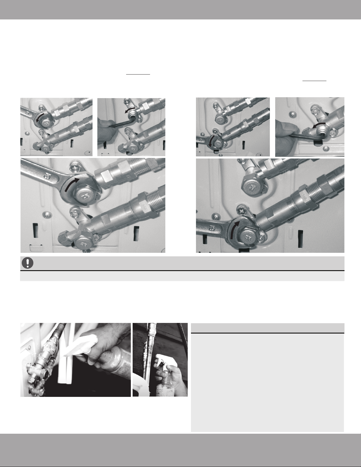
Using the images below as a guide, repeat the same
Using the images below as a guide, remove the cover
1.
on the top valve, using a 19 mm open-ended wrench
or a crescent (adjustable-type) wrench. Then, insert a
5 mm Allen key and open the valve by turning it
counter-clockwise as far as it will go. DO NOT force it.
The valve is now open. Screw the cover back onto the
top valve and tighten it well to ensure that it is
properly sealed.
2.
process for the bottom valve. Remove the cover on
the bottom valve, using a 19 mm open-ended wrench
or a crescent (adjustable-type) wrench. Then, insert a
5 mm Allen key and open the valve by turning it
counter-clockwise as far as it will go. DO NOT force it.
Screw the cover back onto the bottom valve and
tighten it well to ensure that it is properly sealed.
CAUTION
If the valves are not fully opened, it could cause the system to malfunction and suffer damage.
After completing steps 1 and 2, you will now need to check all of the piping connections (at indoor unit and
3.
outdoor unit) for leaks. You can do this by using leak detection spray, or applying a soapy water solution (liquid
detergent/water mixture) to the connection via a spray bottle or brush. If any bubbles begin to form, that
indicates there is a leak, and the connection needs to be retightened. Tighten the connection and recheck it
for leaks. Refer to Electrical and Gas Leaks Checks section of this manual for more information.
IMPORTANT:
You will be asked to check for leaks at the
piping connections multiple times throughout
the following steps of the installation, because
the pressures within the lines will change once
the unit is turned on and this could reveal
leaks not present during the initial check.
These are imperative to make sure your
connections are not allowing refrigerant to
escape the system. When checking for leaks, if
any bubbles form, it indicates the system has
a leak and the screw connector needs to be
retightened. For more information about
checking for leaks, please refer to the
Electrical and Gas Leak Checks section of the
manual.
mrcool.com
Page 28
Page 30
Refrigerant Piping Connection
Step 6: Wrap piping connections
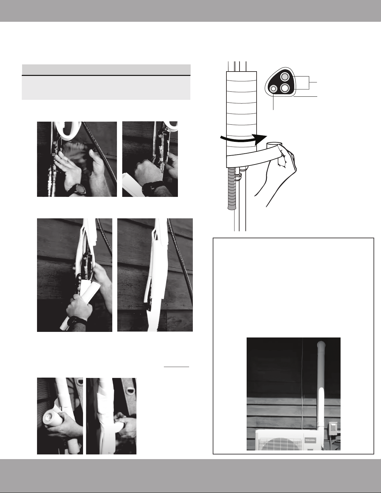
In this step you will wrap and insulate the exposed line
connections coming from the indoor air handler.
IMPORTANT
Do not complete these steps until all of the
refrigerant piping connections have been checked
for leaks.
1.
Wrap the connectors at the indoor air handler tightly
with the supplied sound deadening pads.
Refrigerant
piping
Non-Adhesive U.V.
Tape
Drain hose
2.
Now, place the supplied insulation material over the
connectors and exposed refrigrant piping
Now you will wrap the insulation, refrigerant piping, and
3.
drain hose together tightly using the supplied Non-adhesive U.V. tape. The drain pipe will need to be at the
bottom of the bundle (Refer to Fig. 6.2). DO NOT wrap
the end of the drain hose
Fig. 6.2
If you would like the exterior piping on the
side of your home to have a sleeker, more
attractive look and add some extra protection
in the process, you can purchase a MRCOOL
LineGuard® Line Set Cover. This will encase
your refrigerant piping and lines, protecting
them from harsh weather conditions and sun
exposure, which will extend the life of your
system. These covers are available in various
sizes to fit your particular application.
Page 29
mrcool.com
Page 31
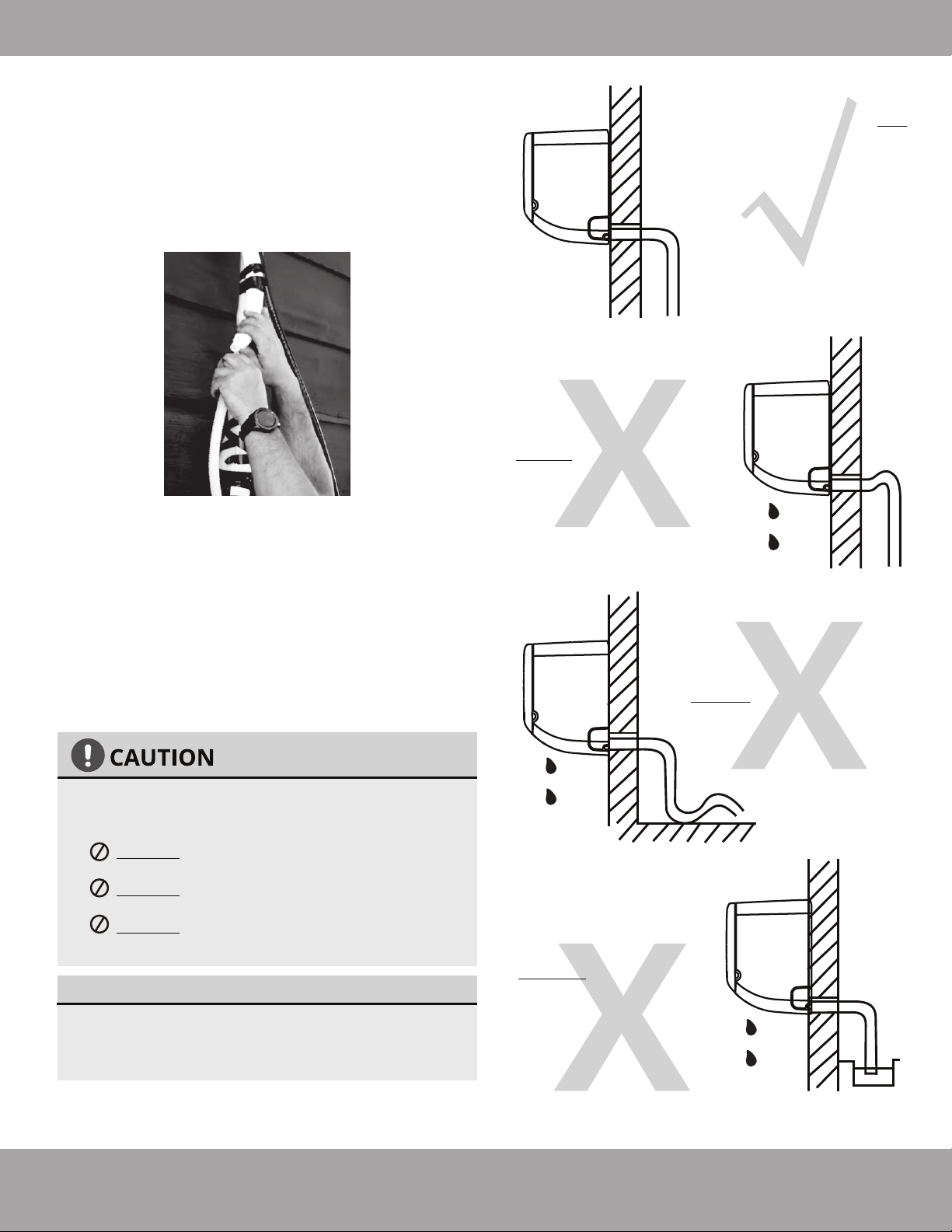
Refrigerant Piping Connection
Step 7: Connect Drain Pipe
In this step you will connect the drain hose extension to
the drain hose exiting from the indoor unit that is within
the piping bundle you wrapped in the previous steps.
Securely connect the drain hose extension to the
1.
drain piping from the indoor unit.
Make sure there are NO
kinks or dents in the
hose to ensure proper
drainage.
Fig. 4.5a
NOT CORRECT
KINKS in the drain hose
will create water traps.
Using example Fig. 4.5a as a guide, make sure
2.
your drain pipe is run in a similar manner. The
other examples in Fig 4.5 represent things you
should avoid when installing your drain pipe.
Remove the air filter from the indoor unit and
3.
pour a small amount of water into the drain
pan to ensure that the water exits the bottom
of the unit and flows through the drain and
drain pipe smoothly.
NOTE ON DRAIN HOSE PLACEMENT
Make sure to arrange the drain hose correctly
according to Fig. 4.5a.
DO NOT
DO NOT
DO NOT put the end of drain hose in water
or a container that will collect water.
ENSURE UNUSED DRAIN HOLE IS PLUGGED
To prevent unwanted leaks, be sure that the
factory installed hollow center rubber plug is
installed in the unused drain hole.
kink the drain hose.
create a water trap.
Fig. 4.5b
NOT CORRECT
DENTS in the drain hose
will create water traps.
Fig. 4.5c
NOT CORRECT
DO NOT place the end
of the drain hose in
water or in containers
that collect water.
This will prevent
proper drainage.
Fig. 4.5d
mrcool.com
Page 30
Page 32
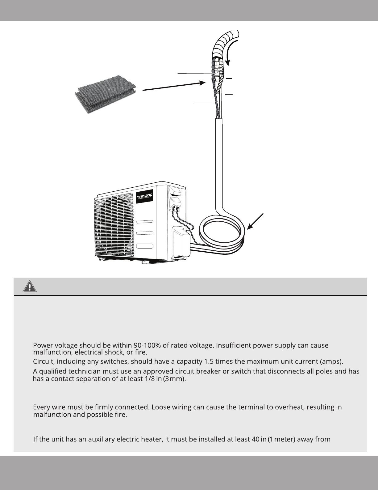
Refrigerant Piping Connection
Wrapped piping with U.V. Tape
Quick Connect
connections
Sound Deadening Pads to
wrap connections once
connected and checked for
leaks.
®
Drainage Pipe
Refrigerant Piping
Signal Cable
(inside conduit)
Coiled & Wrapped
excess refrigerant line
Outdoor Unit (Exterior / Condenser)
BEFORE PERFORMING ELECTRICAL WORK, READ THESE REGULATIONS
All wiring must comply with local and national electrical codes.
1.
2. All electrical connections must be made according to the
the panels of both the indoor and outdoor units.
If there is a serious safety issue with the power supply, stop work immediately. Explain your
3.
to the client, and refuse to install the unit until the safety issue is properly resolved.
Electrical Connection Diagram
located on
4.
5.
6.
7. Do not connect another appliance to the same circuit as the unit.
8. Make sure to properly ground the unit.
9.
Do not allow wires to touch or rest against the refrigerant tubing, compressor, or any other moving
10.
part within the unit.
11.
combustible materials.
Page 31
mrcool.com
Page 33
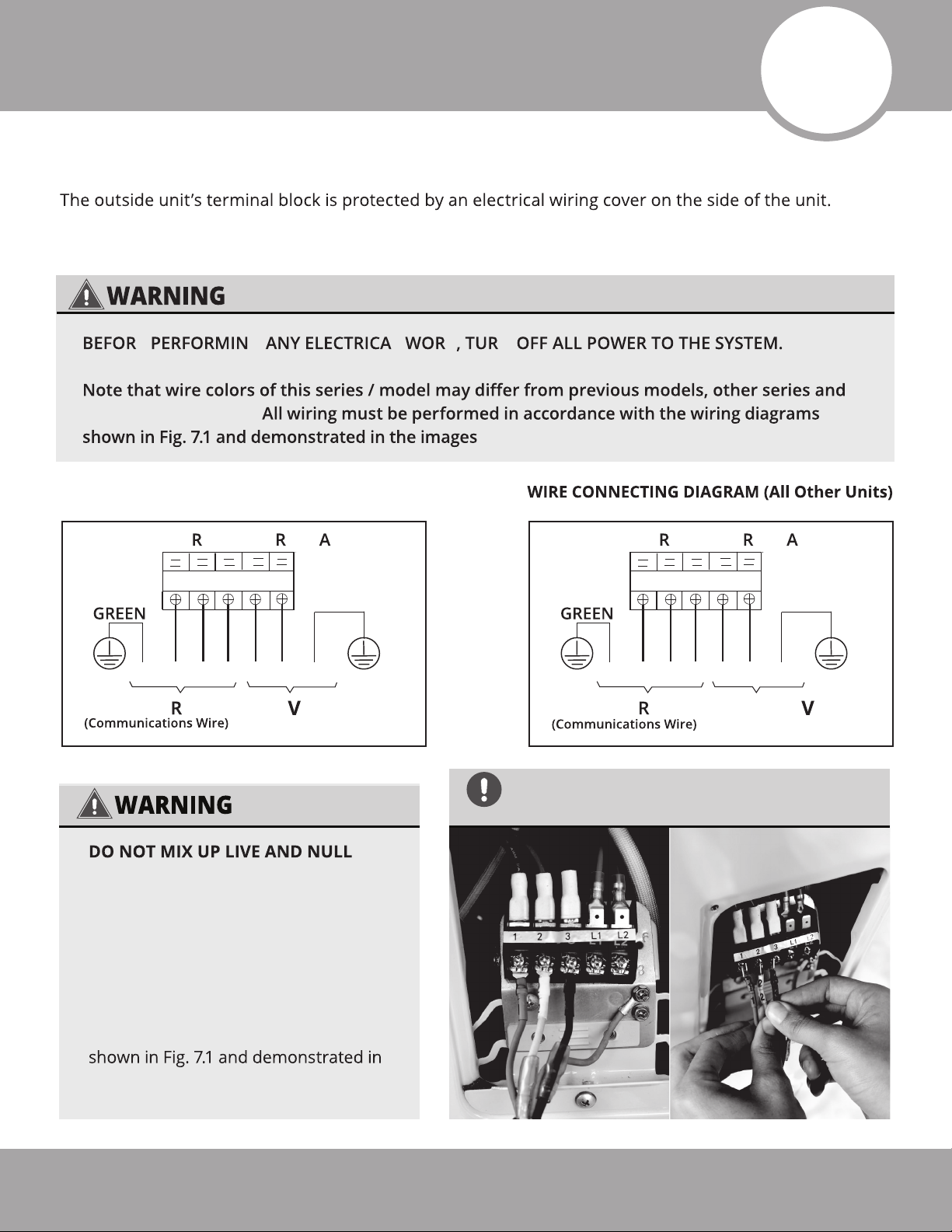
Electrical Connections
Connect signal and power cables
A comprehensive wiring diagram is printed on the inside of the wiring cover.
E G L K N
general conventions.
below.
WIRE CONNECTING DIAGRAM (12K Unit Only)
7
OUTDOO UNIT TE MIN L
3
2 L N1
Y/G
RED
TO INDOO UNIT
WIRES
This is dangerous and can cause the air
conditioning unit to malfunction. Make
sure you clearly distinguish the Live (”L”)
Wires from the other wires.
BLACK
WHITE
L N
3
21
115
POWER SUPPLY
Fig. 7.1
OUTDOO UNIT TE MIN L
3
2 L1L21
Y/G
RED
TO INDOO UNIT
WIRES AND TERMINALS ARE NUMBERED TO
CORRESPOND WITH ONE ANOTHER AS SHOWN
BELOW.
BLACK
WHITE
L1 L2
3
21
208/ 230
POWER SUPPLY
All wiring must be performed in
accordance with the wiring diagrams
the images shown here.
mrcool.com
Page 32
Page 34
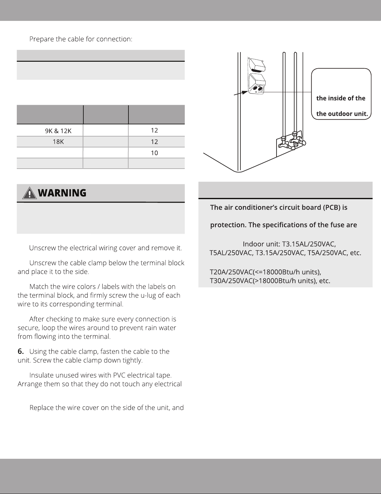
1.
SELECT THE CORRECT CABLE
Electrical Connections
• See table below for gauge requirements
Minimum Wire Gauge
Model Series
24K
36K
ALL WIRING MUST BE INSTALLED STRICTLY
IN ACCORDANCE WITH THE WIRING
DIAGRAM LOCATED AS SHOWN IN FIG 7.2.
for Power Cables
Appliance
Amps(A)
20
20
30
40
2.
AWG
8
Outdoor Unit
Wiring Diagram
Cover
is located on
wire cover on
Fig. 7.2
NOTE ABOUT FUSE SPECIFICATIONS
designed with a fuse to provide overcurrent
printed on the circuit board.
EXAMPLE
3.
4.
5.
7.
or metal parts.
8.
screw it in place.
EXAMPLE Outdoor unit:
Page 33
mrcool.com
Page 35
Refrigerant Piping Connection
8
8
Manual.
BEFORE TEST RUN
NOTE:
DURING TEST RUN
IF ELECTRICAL LEAKAGE IS DETECTED
WARNING – RISK OF
ELECTRIC SHOCK
ALL WIRING MUST BE INSTALLED BY A
LICENSED ELECTRICIAN AND COMPLY WITH
LOCAL, STATE, AND NATIONAL ELECTRICAL
CODES.
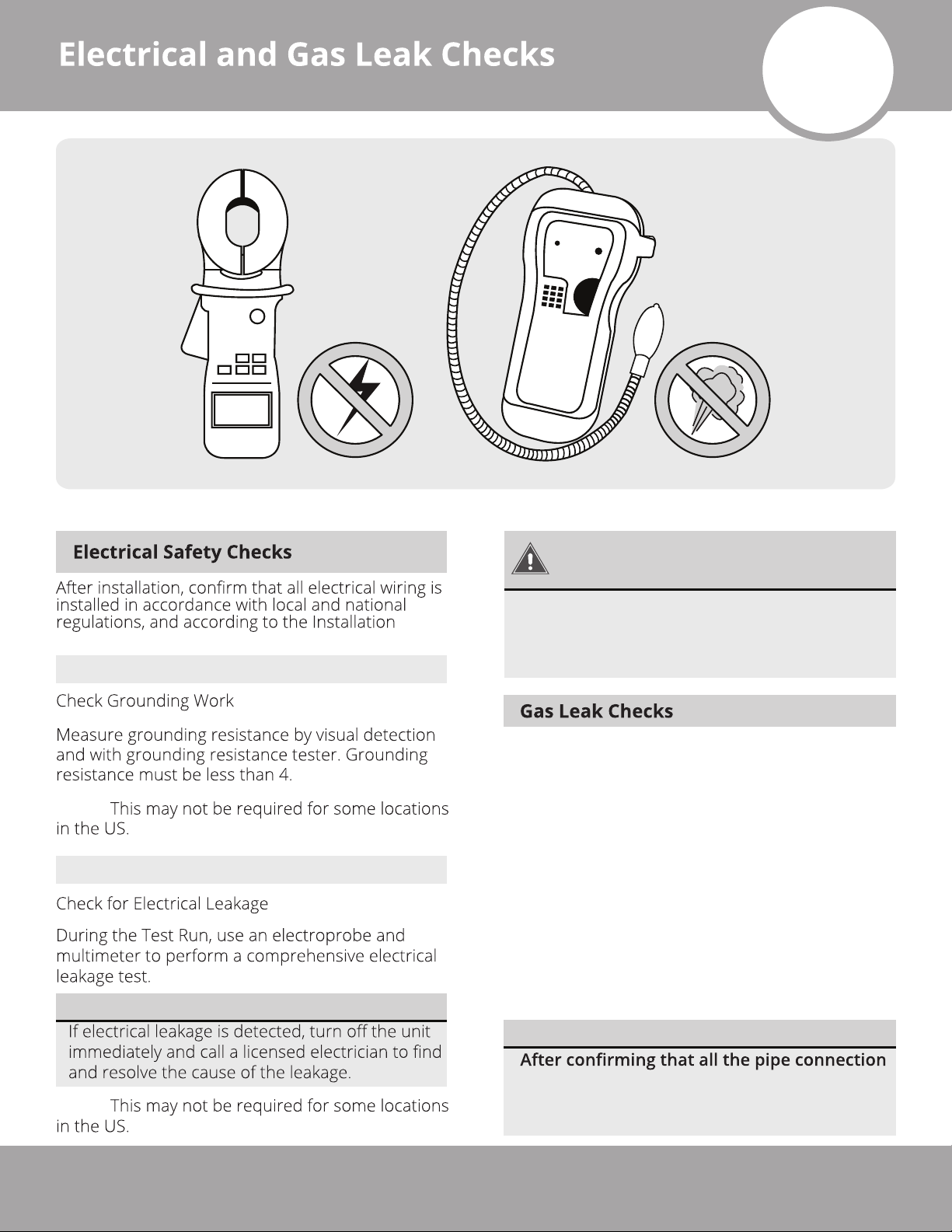
There are two different methods to check for
gaseous leaks.
Soap and Water Method
Using a soft brush or spray bottle, apply a soapy
water solution to all of the pipe connection points of
the indoor and outdoor units, watching to see if any
bubbles form. The presence of bubbles indicates
there is a leak.
Leak Detector Method
If using a leak detector, refer to the device’s
operation/instruction manual for proper usage
instructions.
NOTE:
AFTER PERFORMING GAS LEAK CHECKS
points DO NOT leak, replace the valve cover
on the outside unit and wrap and insulate the
piping connections of the indoor unit.
mrcool.com
Page 34
Page 36
Test Run
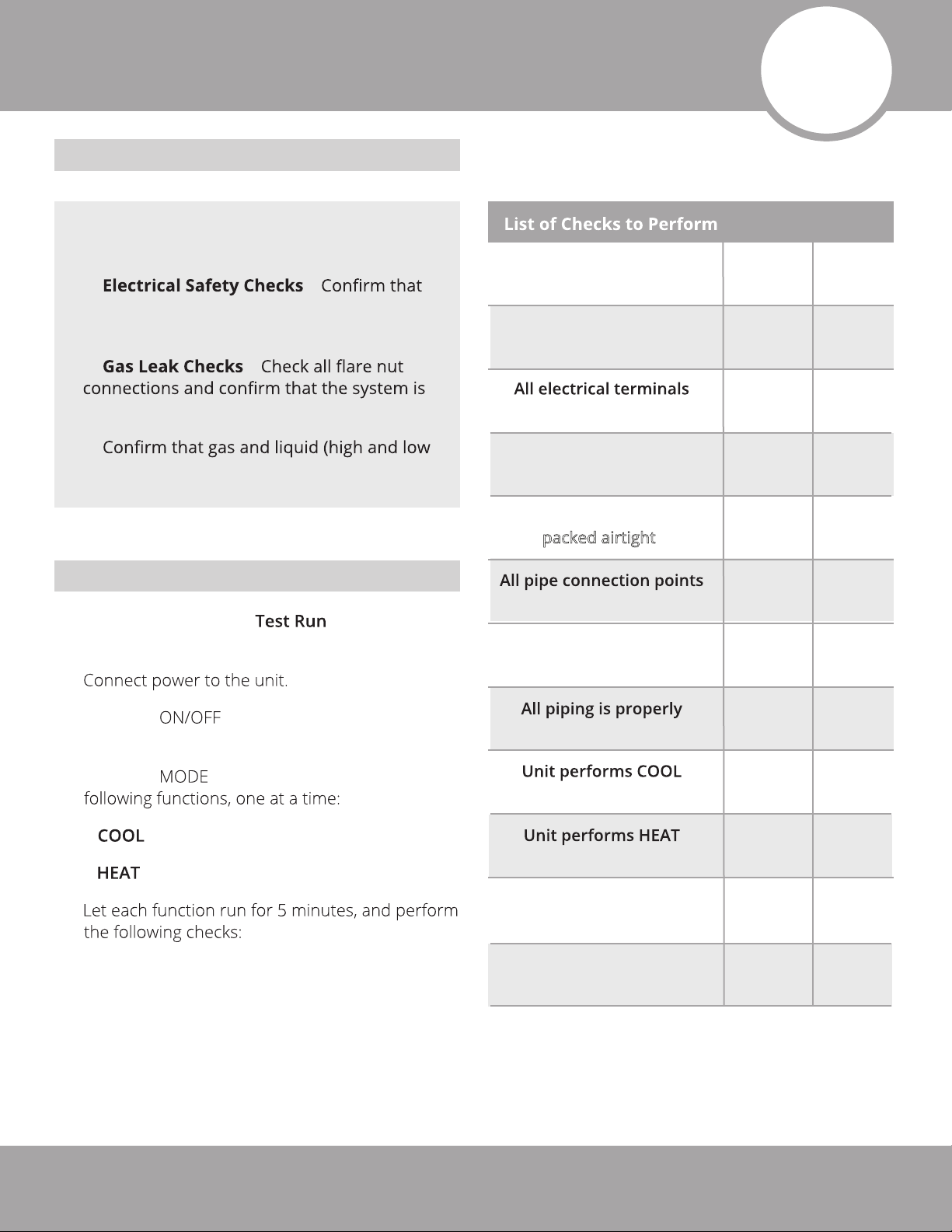
Before Test Run
Refrigerant Piping Connection
9
Only perform test run after you have
completed the following steps:
•
the electrical system is safe and operating
properly
•
not leaking
•
pressure) valves are fully open
Test Run Instructions
You should perform the for at least
30 minutes.
1.
–
–
No electrical leakage
Unit is properly grounded
properly covered
Indoor and outdoor units
are solidly installed
Wall Penetration Sleeve is
packed airtight
do not leak
Water drains properly
from drain hose
PASS/FAIL
Outdoor (2):
Indoor (2):
2. Press the button on the remote
controller to turn it on.
3. Press the button to scroll through the
• – Select lowest possible temperature
• – Select highest possible temperature
4.
insulated
function properly
function properly
Indoor unit louvers rotate
properly
Indoor unit responds to
remote control
Page 35
mrcool.com
Page 37
DOUBLE-CHECK PIPE CONNECTIONS
During operation, the pressure of the
refrigerant circuit/piping will increase. This
may reveal leaks that were not present during
your initial leak check. Take time during the Test
section for instructions.
5.
a.
operating temperature.
b.
Test Run
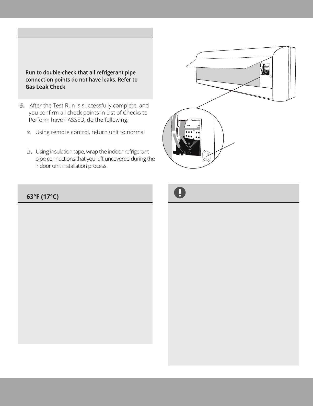
Manual Control Button
IF AMBIENT TEMPERATURE IS BELOW
If the ambient temperature is below
63°F (17°C), the remote controller cannot be
used to turn on the COOL function. In this
instance, you will need to use the MANUAL
CONTROL BUTTON to test the COOL
function. Follow the steps below to access
this function:
Lift the front panel of the indoor unit,
1.
and continue to raise it until it clicks
into place and becomes
self-supporting.
2.
The MANUAL CONTROL BUTTON is
located on the right-hand side of the
unit (Refer to Fig 9.1). Press it 2 times
to select the COOL function.
Perform Test Run as normal.
3.
Fig. 9.1
THANK YOU
Thank you for purchasing a MRCOOL
ductless mini-split heating and air
conditioning product.
MRCOOL is a young, family-owned company,
so we are truly thankful you trusted us with
your business. Should you ever need
technical support, or just have questions
about your MRCOOL product, or any of the
other products we offer, please do not
hesitate to call us at (270)-366-0457.
Also, if you can spare a few minutes today,
and leave a review of your new MRCOOL®
product on the partner site where you
purchased it, it would really mean a lot to
us. We are always looking for ways to
improve, and real reviews, from actual
customers like yourself, are vital and
invaluable to our growing company.
mrcool.com
Thank you for being a valued customer!
Page 36
Page 38
10
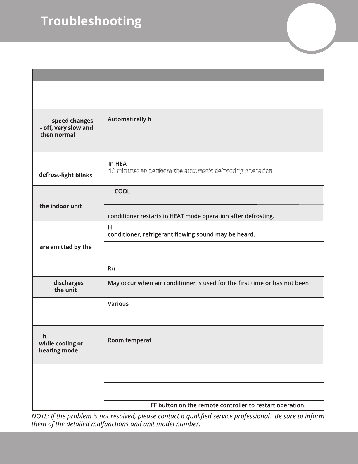
The following events may occur during normal operation, and may not indicate a malfunction.
Symptom Cause
Operation is
delayed after restart
The protection circuit will prevent the compressor from operating for roughly
3 minutes, after a sudden ON-OFF operation of the power supply, in order
to prevent a blowout of the fuse.
Fan
Heating operation
stops suddenly and
Mist coming out of
Low volume sounds
air conditioner
Dust
from
appens in heating mode :
--prevents cold air blowing onto occupants when heating operation starts
--perform automatic defrosting operation
--perform low temperature heating operation
T mode, the indoor unit temporarily stops for a maximum of
10 minutes to perform the automatic defrosting operation.
In mode, a mist generated by condensation formed with sudden
cooling process may be emitted.
Mis
t may generate due to moisture from defrosting process when the air
issing sound -- during operation or immediately after stopping the air
Squeaking sound -- normal expansion and contraction of plastic and
metal parts caused by temperature change during the operation.
shing air -- when louver resets its position.
used for a long time.
Emits a peculiar
odor
C
Operation is erratic,
unpredictable or
unresponsive
Page 37
anges to fan only
smells generated from interior textile, furniture, or cigarette smoke
absorbed into the air conditioner may be emitted. If not the case, contact a
local dealer or your installation contractor.
ure reaches the temperature setting of the remote control.
If not the case, contact a local dealer or your installation contractor.
Interference from cell phone towers and remote boosters may cause the
unit to malfunction.
Turn power off at the unit and at the circuit breaker, wait 10 seconds and
turn power back on
Press the ON/O
mrcool.com
Page 39
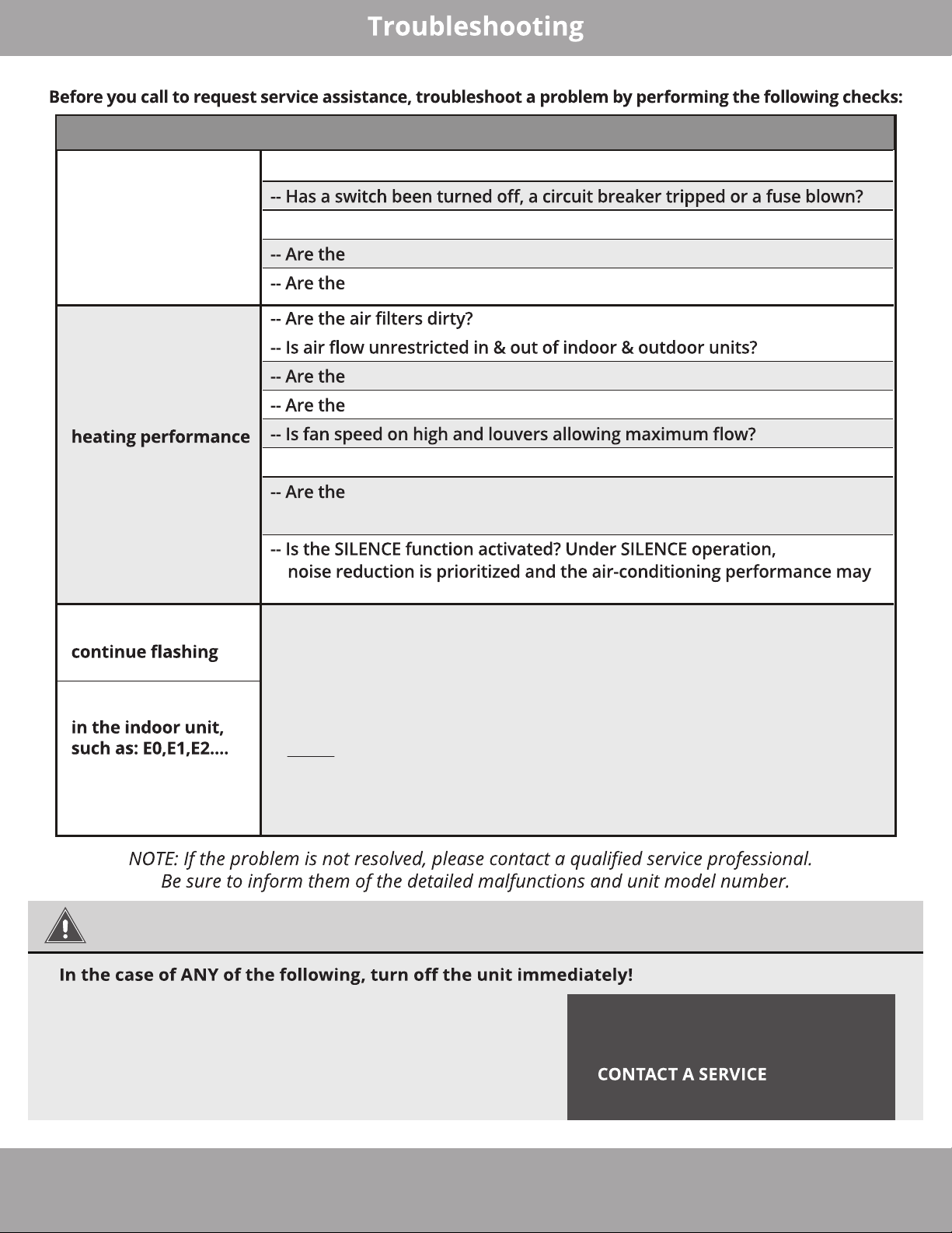
Symptom Diagnostic
-- Is there a power failure?
Unit will not operate
-- Is the timer operating?
batteries used in the remote controller exhausted?
batteries used in the remote controller installed properly?
temperature and mode settings correct?
Poor cooling or
Indicator lamps
Error code appears
P1,P2,P3.....
or F1, F2,F3.....
windows or doors left opened?
-- Is direct or strong sunlight shining into the room in cooling operation?
re other heat generating devices (such as a computers operating),
or too many people in the room in cooling operation?
become lower.
The unit may stop operation or continue to run in a safety condition
--
(depending on the model). The fault may be recovered automatically by
waiting for about 10 minutes. If this does not resolve the fault, disconnect
the power and then reconnect it. If the problem still exists after the
power has been restored, disconnect the power and contact the nearest
customer service center.
NOTE: The wire colors of this series/model may differ from that of previous
models, other series, and general wiring conventions. All wiring must be
performed in accordance with the wiring diagrams, shown in Section 7 (Refer
to Fig. 7.1), and associated images. Wires and terminals are numbered to
match accordingly.
WARNING
· Signal/power cable is damaged or abnormally warm
· Burning odor
·
Loud or abnormal sounds
·
A power fuse or circuit breaker trips frequently
·
Water or other objects fall into or out of the unit
mrcool.com
DO NOT ATTEMPT TO CORRECT
THESE ITEMS YOURSELF!
PROFESSIONAL IMMEDIATELY
Page 38
Page 40
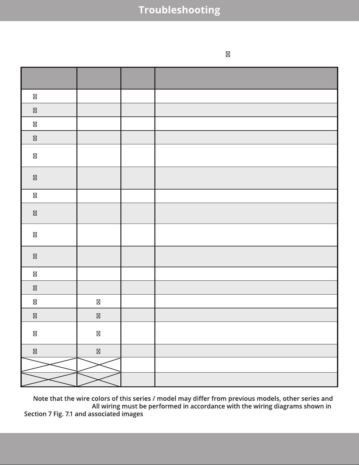
Indoor Unit Error Display
O(light) X(off) (flash)
O
peration LEDTimer LED
D
isplay
L
ED STATUS
1 time
2
times
3 times
4 times
5 times
6 times
7 times
2 times
3 times
4 times
X E
X E
X E
X E
3/E88
X E
X E
X E
O F
O F
O F
0
1
2
4
5
C
1
2
3
Indoor unit EEPROM parameter error
Indoor / outdoor units communication error **
Zero-crossing signal detection error
Indoor fan speed has been out of control
Indoor room temperature sensor T1 open circuit or
short circuit
E
vaporator coil temperature sensor T2 open circuit or
short circuit
Refrigerant leakage detection
Outdoor ambient temperature sensor T4 open circuit
or short circuit
Condenser coil temperature sensor T3 open circuit or
short circuit
Compressor discharge temperature sensor T5 open
circuit or short circuit
5 times
6 times
1 time
2 times
3 times
5 times
**
general conventions.
O F
O F
P
P
P
P
P
P
4
5
0
1
2
4
6
7
Outdoor unit EEPROM parameter error
Outdoor fan speed has been out of control
IPM malfunction or IGBT over-strong current protection
Over voltage or over low voltage protection
High temperature protection of compressor top diagnosis and solution (only for 9k,12k models)
Inverter compressor drive error
Discharge temp sensor
USB Smart Controller module not installed
. Wires and terminals are numbered to match accordingly.
Page 39
mrcool.com
Page 41

®
™
DIY
Consult with the sales agency or manufacturer for details.
E Star
Series
 Loading...