

Page 1

Troubleshooting &
Solutions Guide
4th Generation
®
DIY
Due to updates and constantly improving performance, the information and instructions
within this manual are subject to change without notice. Please visit
www.mrcool.com/documentation to ensure you have the latest version of this manual.
E Star™
Version Date: 10-22-21
Series
Page 2

Troubleshooting
Contents
1. Safety Caution .......................................................................................................3
2. General Troubleshooting ......................................................................................4
3. Complain Record Form ..........................................................................................6
4. Information Inquiry ...............................................................................................8
5. Error Diagnosis and Troubleshooting Without Error Code ...............................11
5.1 Remote maintenance ...................................................................................11
5.2 Field maintenance .......................................................................................12
6. Quick Maintenance by Error Code ......................................................................17
7. Troubleshooting by Error Code ...........................................................................18
7.1 EH 00 / EC 51 (EEPROM parameter error diagnosis and solution) ...........18
7.2 EL 01 (Indoor and outdoor unit communication error diag. and solution).. 19
7.3 EH 02 (Zero-crossing detection error diagnosis and solution) . ................... 21
7.4 EH 03 / EC 07 (Fan speed is operating outside of the normal range
diagnosis and solution) .............................................................................. 22
7.5 EH 60/EH 61/EC 53/EC 52/EC 54/EC 56 (Open circuit or short circuit of
temperature sensor diagnosis and solution) ............................................... 25
7.6 EH 0b (Indoor PCB / Display board communication error diagnosis and
solution) ..................................................................................................... 26
7.7 EL 0C (Refrigerant Leakage Detection diagnosis and solution) ................ 27
Page 3

Troubleshooting
7.8 PC 08 (Overload current protection diagnosis and solution) .................... 28
7.9 PC 00 (IPM malfunction or IGBT over-strong current protection diagnosis
and solution) ............................................................................................. 29
7.10 PC 01 (Over voltage or too low voltage protection diag. and solution)...... 30
7.11 PC 02 (High temperature protection of IPM module or high pressure
protection diagnosis and solution) ............................................................ 31
7.12 PC 04 (Inverter compressor drive error diagnosis and solution) ............... 33
Contents
7.13 PC 03 (Low pressure protection diagnosis and solution) .......................... 34
8. Check Procedures .. ............................................................................................. 36
Page 4

1. Safety Caution
WARNING
Be sure to turn off all power supplies or disconnect all wires to avoid electric shock.
While checking indoor/outdoor PCB, please equip oneself with anti-static gloves or wrist
strap to avoid damage to the board.
WARNING
Electricity remains in capacitors even when the power supply is off.
Ensure the capacitors are fully discharged before troubleshooting.
Test the voltage between P and N on back of the main PCB with multimeter. If the voltage is lower than 36V, the
capacitors are fully discharged.
Note: This picture is for reference only. Actual appearance may vary.
Troubleshooting 3
Page 5

2. General Troubleshooting
2.1 Error Display (Indoor Unit)
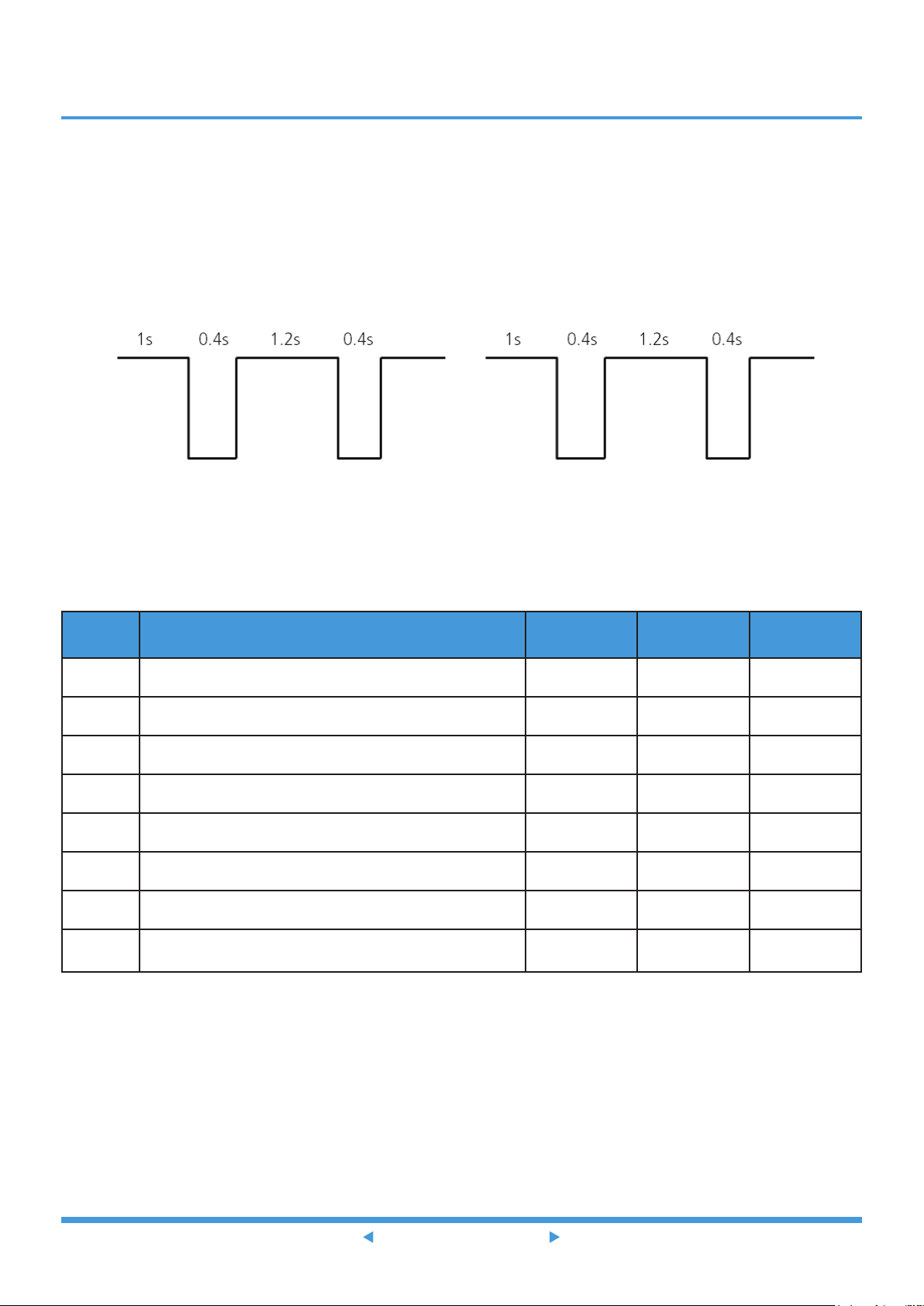
When the indoor unit encounters a recognized error, the operation lamp will flash in a corresponding series, the timer
lamp may turn on or begin flashing, and an error code will be displayed. These error codes are described in the following
table:
Operation
Lamp
1 time OFF
2 times OFF
3 times OFF
4 times OFF
5 times OFF
5 times OFF
5 times OFF
5 times OFF
5 times OFF
6 times OFF
6 times OFF
12 times OFF
Timer
Lamp
LED
Display
EH 00
EL 01
EH 02
EH 03
EC 51
EC 52
EC 53
EC 54
EC 56
EH 60
EH 61
EC 07
Error Information Solution
Indoor unit EEPROM parameter error TS18
Indoor / outdoor unit communication error TS19
Zero-crossing signal detection error (for some models) TS21
The indoor fan speed is operating outside of the normal range TS22
Outdoor unit EEPROM parameter error (for some models) TS18
Condenser coil temperature sensor T3 is in open circuit or has short
circuited
Outdoor room temperature sensor T4 is in open circuit or has short
circuited
Compressor discharge temperature sensor TP is in open circuit or
has short circuited
Evaporator coil outlet temperature sensor T2B is in open circuit or
has short circuited (for free-match indoor units)
Indoor room temperature sensor T1 is in open circuit or has short
circuited
Evaporator coil temperature sensor T2 is in open circuit or has short
circuited
The outdoor fan speed is operating outside of the normal range
for some models)
TS25
TS25
TS25
TS25
TS25
TS25
TS22
9 times OFF
8 times OFF
7 times FLASH
2 times
3 times FLASH
5 times FLASH
1 time FLASH
7 times FLASH
1 times ON
FLASH PC 01
EH 0b
EL 0C
PC 00
PC 02
PC 04
PC 08
PC 03
--
Indoor PCB / Display board communication error TS26
Refrigerant leak detected TS27
IPM malfunction or IGBT over-strong current protection TS29
Over voltage or over low voltage protection TS30
High temperature protection of IPM module or High pressure
protection (for some models)
Inverter compressor drive error TS33
Current overload protection (for some models) TS28
Low pressure protection (for some models) TS34
Indoor units mode conflict (match with multi outdoor unit)
TS31
--
Troubleshooting 4
Page 6
For other errors:
The display board may show a garbled code or a code undefined by the service manual. Ensure that this code is not a
temperature reading.
Troubleshooting:
Test the unit using the remote control. If the unit does not respond to the remote, the indoor PCB requires replacement.
If the unit responds, the display board requires replacement.
LED flash frequency:
... ...
2.2 Error Display (For Some Outdoor Units)
There are 2 LED lights (RED color and GREEN color) welded in outdoor main board. After power on, LED show different
actions when encounter different problems.
No. Problem LED(GREEN) LED(RED) Solution
1 Standby normally
2 Operate normally
3 Compressor driven chip EEPROM parameter error
4 IPM malfunction or IGBT over-strong current protection
5 Over voltage or too low voltage protection
6 Inverter compressor drive error
7 Inverter compressor drive error
8
Communication error between outdoor main chip and
compressor driven chip
ON OFF -
OFF ON -
ON FLASH
Flash OFF
ON ON
OFF FLASH
Flash LIGHT
flash FLASH
TS19
TS30
TS31
TS34
TS34
TS19
Troubleshooting 5
Page 7

3. Complain Record Form
Complain Record Form
Request No.: Date:
Installation Date: Service Date:
Customer Information
Name Telephone No.
Home Address
Email
Product Information
Indoor Unit Model Outdoor Unit Model
Serial No. of indoor unit
Serial No. of outdoor unit
Working Mode □Cooling □Heating □Fan only □Dry
Setting temperature °C / °F Fan speed
Temperature of air inlet °C / °F
Temperature of air
outlet
□Turbo □High □Medium □Low
□Auto
°C / °F
Installation / Condition Information
Indoor temperature °C / °F Indoor humidity %RH
Outdoor temperature °C / °F Outdoor humidity %RH
Length of Connecting pipe Pipe diameter Gas pipe: Liquid pipe:
Length of Wiring wire diameter
System Running Pressure MPa or Bar or PSI
Room size (L*W*H)
Photo of Installation of Indoor unit
(Photo #1)
Failure Description
Error Code of Indoor unit
Unit does not start
Remote control does not work
Indoor display shows nothing
No cooling or heating at all
Less cooling or heating
Unit starts but stops shortly
High noise
High vibration
Photo of Installation
of Outdoor unit
(Photo #2)
Code of Outdoor
PCB
Troubleshooting 6
Page 8
Parameter Checking information by Remote controller
Displaying code Displaying code meaning Display value Display value meaning
T1 Room temperature
T2 Indoor coil temperature
T3 Outdoor coil temperature
T4 Ambient temperature
Tb
TP Discharge temperature
TH Sunction temperature
FT Targeted Frequency
Fr Actual Frequency
IF Indoor fan speed
OF Outdoor fan speed
LA EXV opening steps
CT
ST
A0, A1, b0, b1, b2, b3, b4,
b5, b6, dL, Ac, Uo, Td, dA,
dS, dT
Outlet temperature of
indoor coil
Compressor continuous
running time
Causes of compressor
stop.
Reserved
□Approved
□More Proof needed
□Rejected
Approval from Manufacturer
Troubleshooting 7
Page 9

4. Information Inquiry
• To enter information inquiry status, complete the following procedure within ten seconds:
• Press LED (or DO NOT DISTURB) 3 times.
• Press SWING (or AIR DIRECTION) 3 times.
• Finish 1 and 2 within 10 seconds, you will hear beeps for two seconds, which means the unit goes into parameter
checking mode.
• Use the LED (or DO NOT DISTURB) and SWING (or AIR DIRECTION) buttons to cycle through information displayed.
• Pressing LED (or DO NOT DISTURB) will display the next code in the sequence. Pressing SWING (or AIR
DIRECTION) will show the previous.
• The following table shows information codes. The screen will display this code for two seconds, then the information
for 25 seconds.
Troubleshooting 8
Page 10

Displayed code Explanation
Displayed
value
Meaning Additional Notes
T1
T2
T3
T4
Tb
TP
TH
FT
Fr
IF
OF
Room temperature
Indoor coil
temperature
Outdoor coil
temperature
Ambient
temperature
Outlet temperature
of indoor coil
Discharge
temperature
Suction temperature
Targeted frequency
Actual frequency
Indoor fan speed
Outdoor fan speed
-1F,-1E,-1d,-1c,1b,-1A
-19—99
A0,A1,…A9
b0,b1,…b9
c0,c1,…c9
d0,d1,…d9
E0,E1,…E9
F0,F1,…F9
0
1,2,3,4
14-FF
-25,-24,-23,-22,
-21,-20
-19—99
100,101,…109
110,111,…119
120,121,…129
130,131,…139
140,141,…149
150,151,…159
OFF
Low speed, Medium
speed, High speed,
Turbo.
Actual fan speed is
equal to the display
value converted to
decimal value and
multiplied by 10. This
is measured in RPM.
1. All displayed temperatures
use actual values.
2. All temperatures are
displayed in °C regardless
of remote used.
3. T1, T2, T3, T4, and T2B
display ranges from -25 to
70 °C. TP display ranges
from -20 to 130 °C.
4. The frequency display
ranges from 0 to 159HZ.
5. If the actual values exceed
or fall short of the defined
range, the values closest
to the maximum and
minimum values will be
displayed.
N/A
Used for some large capacity
motors.
Used for some small capacity
motors.
The display value is 14-FF
(hexadecimal). The
corresponding fan speed
ranges from 200 to 2550 RPM.
LA
CT
ST
EXV opening angle 0-FF
Compressor
continuous running
time
Causes of
compressor stop
0-FF 0-255 minutes
0-99
Actual EXV opening
value is equal to
the display value
converted to decimal
value and then
multiplied by 2.
For a detailed
explanation, contact
technical support.
Troubleshooting 9
-
If the actual value exceeds
or falls short of the defined
range, the value closest to the
maximum and minimum will
be displayed.
-
Page 11

Displayed code Explanation
A0
A1
0
1
2
3
4
5
Reserved
6
Displayed
value
0-FF
2-28
5-20
Meaning Additional Notes
- -
L
A
U
T
A
5
T
5-25
Troubleshooting 10
Page 12

5. Error Diagnosis and Troubleshooting Without Error Code
WARNING
Be sure to turn off unit before any maintenance to prevent damage or injury.
5.1 Remote maintenance
SUGGESTION: When troubles occur, please check the following points with customers before field maintenance.
No. Problem Solution
1 Unit will not start TS13 - TS14
2 The power switch is on but fans will not start TS13 - TS14
3 The temperature on the display board cannot be set TS13 - TS14
4 Unit is on but the wind is not cold (hot) TS13 - TS14
5 Unit runs, but shortly stops TS13 - TS14
6 The unit starts up and stops frequently TS13 - TS14
7 Unit runs continuously but insufficient cooling (heating) TS13 - TS14
8 Cool can not change to heat TS13 - TS14
9 Unit is noisy TS13 - TS14
Troubleshooting 11
Page 13

5.2 Field maintenance
1 Unit will not start TS15 - TS16
2 Compressor will not start but fans run TS15 - TS16
3 Compressor and condenser (outdoor) fan will not start TS15 - TS16
4 Evaporator (indoor) fan will not start TS15 - TS16
5 Condenser (Outdoor) fan will not start TS15 - TS16
6 Unit runs, but shortly stops TS15 - TS16
7 Compressor short-cycles due to overload TS15 - TS16
8 High discharge pressure TS15 - TS16
9 Low discharge pressure TS15 - TS16
10 High suction pressure TS15 - TS16
Problem Solution
11 Low suction pressure TS15 - TS16
12 Unit runs continuously but insufficient cooling TS15 - TS16
13 Too cool TS15 - TS16
14 Compressor is noisy TS15 - TS16
15 Horizontal louver cannot revolve TS15 - TS16
Troubleshooting 12
Page 14
1. Remote Maintenance
Possible causes of trouble
Unit will not start
The power switch is on but fans will not start
The temperature on the display board cannot be set
Unit i s on but the wind i s not col d (hot)
Unit runs , but shortly stops
The unit sta rts up and stops frequently
Unit runs connuousl y but insu ci ent cooling (hea ng)
Cool can not change to heat
Unit i s noi s y
Refrigerant Circuit
Electrical Circuit
nd defrosng frequently
Fan mode
Broken remote control
The main power tripped
Power failure
Loose connecons
Faulty transformer
The remote control is powered o
The voltage is too high or too low
Dirty condenser ns
Dirty air ter
The ambient temperature is too high/low when the mode is cooling/heang
The seng temperature is higher/lower than the room's(cooling/heang)
SILENCE funcon is acvated (oponal funcon)
Frosng a
Test method / remedy
Inspect connecons - ghten
Close the power switch
Test voltage
Change the transformer
Replace the baery of the remote control
Test voltage
Troubleshooting 13
Adjust the seng temperature
Turn the AC later
Clean
Clean or replace
Replace the remote control
Adjust to cool mode
Turn o SILENCE funcon.
Turn the AC later
Page 15

1. Remote Maintenance
Possible causes of trouble
Unit will not start
The power switch is on but fans will not start
The temperature on the display boar d cannot be set
Unit i s on but the wind i s not col d (hot)
Unit runs , but shortly stops
The unit sta rts up and stops frequently
Unit runs connuousl y but insu ci ent cooling (heang)
Cool can not change to heat
Unit i s noi s y
Others
Heavy load condion
Loosen hold down bolts and / or screws
Bad airproof
The air inlet or outlet of either unit is blocked
Shipping plates remain aached
Interference from cell phone towers and remote boosters
Test method / remedy
Check heat load
Tighten bolts or screws
Close all the windows and doors
Remove the obstacles
Reconnect the power or press ON/OFF buon on remote control to restart operaon
Remove them
Troubleshooting 14
Page 16

2. Field Maintenance
Possible causes of trouble
Electrical Circuit
Unit will not start
Compressor will not start but fans run
Compressor and condens er (outdoor) fa n will not start
Evaporator (indoor ) fan will not start
Condenser (Outdoor) fan will not sta rt
Unit runs , but shortly stops
Compressor s hort-cycl es due to overl oad
High dis charge pressure
Low dis cha rge pressure
High s ucon pr essure
Low suc on pressure
Unit runs connuous ly but insu cient cooling
Too cool
Compress or is noi sy
Hori zontal louver ca n not revolve
Blown fuse or varistor
Power failure
Loose connecons
Shorted or broken wires
Safety device opens
Faulty transformer
Faulty thermostat / room temperature sensor
Wrong seng place of temperature sensor
Shorted or open capacitor
Faulty magnec contactor for compressor
Faulty magnec contactor for fan
Low voltage
Faulty stepping motor
Shorted or grounded compressor
Shorted or grounded fan motor
Test method / remedy
Test voltage
Inspect fuse type & size
Inspect connecons - ghten
Test connuity of safety device
Test circuits with tester
Test connuity of thermostat / sensor & wiring
Place the temperature sensor at the central of the air inlet grille
Troubleshooting 15
r
Check resistance with mulmeter
Check control circuit with tester
Check capacitor with tester
Test connuity of coil & c ontacts
Test connuity of coil & c ontacts
Test voltage
Check resistance with mulmeter
Replace the stepping moto
Page 17

2.Field Maintenance
Possible causes of trouble
Compressor and condens er (outdoor) fa n will not
start
Recfy piping so as not to contact each other or with external
plate
Refrigerant Circuit
Others
Unit will not start
Compressor will not start but fans run
Evaporator (i ndoor) fan will not s tart
Condenser (Outdoor) fan will not sta rt
Unit runs , but shortly stops
Compressor s hort-cycl es due to overl oad
High dis charge pressure
Low dis cha rge pressure
High s ucon pr essure
Low suc on pressure
Unit runs connuous ly but insu cient cooling
Too cool
Compress or is noi sy
Hori zontal louver ca n not revolve
ansion valve obstructed
Short cyc ling of condensing air
High temperature condensing medium
Air or incompressible gas in refrigerant cycle
Dirty or parally blocked condenser
Insucient air through evaporator c oil
Overcharge of refrigerant
Dirty evaporator coil
Restricted liquid line
Dirty air ter
Shortage of refrigerant
Compressor stuck
Insucient condensing medium
Exp
Inecient compressor
Broken compressor internal parts
Expansion valve or capillary tube closed completely
Leaking power element on expansion valve
Poor installaon of feeler bulb
Heavy load condion
Loosen hold down bolts and / or screws
Shipping plates remain aached
Poor choices of capacity
Contact of piping with other piping or external plate
Test method / remedy
Clean or replace
Clean coil
Check fan
Replace restricted part
Leak test
Replace the compressor
Change charged refrigerant volume
Troubleshooting 16
ve
Replace val
Remove obstruc on to air ow
Remove obstruc on in air or water ow
Clean condenser or remove obstacle
Purge, evacuate and recharge
Remove obstruc on in air or water ow
Replace valve
Test compressor eciency
Replace compressor
Fix feeler bulb
Check heat load
Replace valve
Choose AC of lager capacity or add the number of AC
Tighten bolts or screws
Remove them
Page 18

6. Quick Maintenance by Error Code
If you do not have the time to test which specific parts are faulty, you can directly change the required parts according
the error code.
You can find the parts to replace by error code in the following table.
Error Code
Part requiring replacement
EH 00 EL 01 EH 02 EH 03 EH 60 EH 61 EH 0b EL 0C PC 08
Indoor PCB
Outdoor PCB x x x x x x x
Display board x x x x x x x x
Indoor fan motor x x x x x x x x
T1 sensor x x x x x x x x
T2 Sensor x x x x x x x
Reactor x x x x x x x x
Compressor x x x x x x x x
Additional refrigerant x x x x x x x x
Part requiring
replacement
Indoor PCB
Outdoor PCB
Indoor fan motor x x x x x x x x x x x
Outdoor fan motor x x x x x x x
EC 53 EC 52
x x x x x x x x x x x
EC 54 EC 56 EC 51 EC 07 PC 00 PC 01 PC 02 PC 03 PC 04
x
T3 Sensor x x x x x x x x x x
T4 Sensor x x x x x x x x x x
TP Sensor x x x x x x x x x x
T2B Sensor x x x x x x x x x x
Reactor x x x x x x x x x x
Compressor x x x x x x x x x
IPM module board x x x x x x x
High pressure protector x x x x x x x x x x
Low pressure protector x x x x x x x x x x
Additional refrigerant x x x x x x x x x x
Note: For certain models, outdoor PCB could not be removed separately. In this case, the outdoor electric
control box should be replaced as a whole.
Troubleshooting 17
Page 19

7. Troubleshooting by Error Code
7.1 EH 00 / EC 51 (EEPROM parameter error diagnosis and solution)
Description: Indoor or outdoor PCB main chip does not receive feedback from EEPROM chip.
Recommended parts to prepare:
• Indoor PCB
• Outdoor PCB
Troubleshooting and repair:
Shut off the power supply and
turn it on 2 minutes later.
Is it still displaying
the error code?
YES
Replace the indoor main
PCB(EH 00) /outdoor main
PCB(EC 51).
Remarks:
EEPROM: A read-only memory whose contents can be erased and reprogrammed using a pulsed voltage.
The location of the EEPROM chip on the indoor and outdoor PCB is shown in the following two images:
The unit is operating normally. NO
Note: For certain models, outdoor PCB could not be removed separately. In this case, the outdoor electric
control box should be replaced as a whole. This pictures are only for reference, actual appearance may vary.
Troubleshooting and repair of compressor driven chip EEPROM parameter error and communication error
between outdoor main chip and compressor driven chip are same as EC 51.
Troubleshooting 18
Page 20

7.2 EL 01 (Indoor and outdoor unit communication error diagnosis and solution)
Description: Indoor unit can not communicate with outdoor unit
Recommended parts to prepare:
• Indoor PCB
• Outdoor PCB
• Short-circuited component
Troubleshooting and repair:
Power off, then restart the unit after 2
minutes.
Does the error code
disappear ?
Yes
Check the wiring connection
between indoor and outdoor
unit, are they good?
Yes
Measure the DC voltage between N/L2
and S (Black pin to N/LN, Red pin to S).
For units with main PCB and IPM board
Check the AC voltage of L, N
output to IPM board, is it same
Unplug all the high voltage
components connected to main
PCB such as 4 way valve, heater,
AC fan one by one to check their
resistance.
Unplug electronic expansion valve.
Check if the DC 5V, 12V to main
both
as power input?
Yes
Is there any component
short circuit?
No
Check the DC 5V, 12V
from IPM board to main
PCB, are they normal?
No
PCB are OK
No
No
No
For units without W
Solved
Correct the connection or
change wires
The value is alternative
from negative to positive
The value is fixed and close
to 0
The value is always positive
wire
Check the wiring connection
from outdoor terminal to
outdoor PCB and wiring
between PCBs if there is
more than 1 PCB
Replace main PCBNo
Yes
Yes
Replace short- circuited
component and outdoor
Yes
For units
with W wire
For units with only one
Replace outdoor PCB
Replace short-circuited
component and main
PCB
PCB
Replace coil of electronic
expansion valve
Check the wiring connection
from indoor terminal to indoor
PCB, are they good?
Turn on the unit, check if W
and 1(L) is connected?
Yes
PCB
Yes
Yes
No
Yes
Check if the power LED is
Unplug all the high voltage
components connected to main
PCB such as 4 way valve, heater,
AC fan one by one to check their
resistance. Is there any component
Unplug electronic expansion valve.
Check if power LED is on ?
Replace indoor PCB
No
on?
No
short circuit?
No
Replace IPM board
Note: For certain models, outdoor PCB could not be removed separately. In this case, the outdoor electric
control box should be replaced as a whole.
Troubleshooting 19
Page 21

Remarks:
• Use a multimeter to test the DC voltage between 2 port (or S or L2 port) and 3 port (or N or S port) of outdoor unit.
The red pin of multimeter connects with 2 port (or S or L2 port) while the black pin is for 3 port (or N or S port) .
• When AC is normal running, the voltage is moving alternately as positive values and negative values
• If the outdoor unit has malfunction, the voltage has always been the positive value.
• While if the indoor unit has malfunction, the voltage has always been a certain value.
S and N
or
L2 and S
or
2 and 3
• Use a multimeter to test the resistance of the reactor which does not connect with capacitor.
• The normal value should be around zero ohm. Otherwise, the reactor must have malfunction.
Note: The picture and the value are only for reference, actual condition and specific value may vary.
Troubleshooting 20
Page 22

7.3 EH 02 (Zero crossing detection error diagnosis and solution)
Description: When PCB does not receive zero crossing signal feedback for 4 minutes or the zero crossing signal time
interval is abnormal.
Recommended parts to prepare:
• Connection wires
• PCB
Troubleshooting and repair:
Check the connections and
power supply.
Is it normal?
YES
Indoor main PCB is defective. Replace
indoor main PCB.
NO
Correct the connections. Turn on the
unit when the power supply is good.
Note: EH 02 zero crossing detection error is only valid for the unit with AC fan motor, for other models, this
error is invalid.
Troubleshooting 21
Page 23

7.4 EH 03 / EC 07 (Fan speed is operating outside of normal range diagnosis and solution)
Description: When indoor / outdoor fan speed keeps too low or too high for a certain time, the LED displays the failure
code and the AC turns off.
Recommended parts to prepare:
• Connection wires
• Fan assembly
• Fan motor
• PCB
Troubleshooting and repair:
Power off, then restart the unit after 2 minutes.
Does a problem remain? The unit is operating normallyNO
YES
Shut off the power supply, Rotate
the fan by hand.
Does it turn easily? Find the cause of the problem and resolve itNO
YES
Check the wiring of fan motor.
Is it improperly wired?
YES
Measure the voltage for
the fan motor from the PCB.
Is it within normal parameters?
YES
Replace the fan motor
Ensure proper connections
Replace the PCBNO
Note: For certain models, outdoor PCB could not be removed separately. In this case, the outdoor electric
control box should be replaced as a whole.
Troubleshooting 22
Page 24

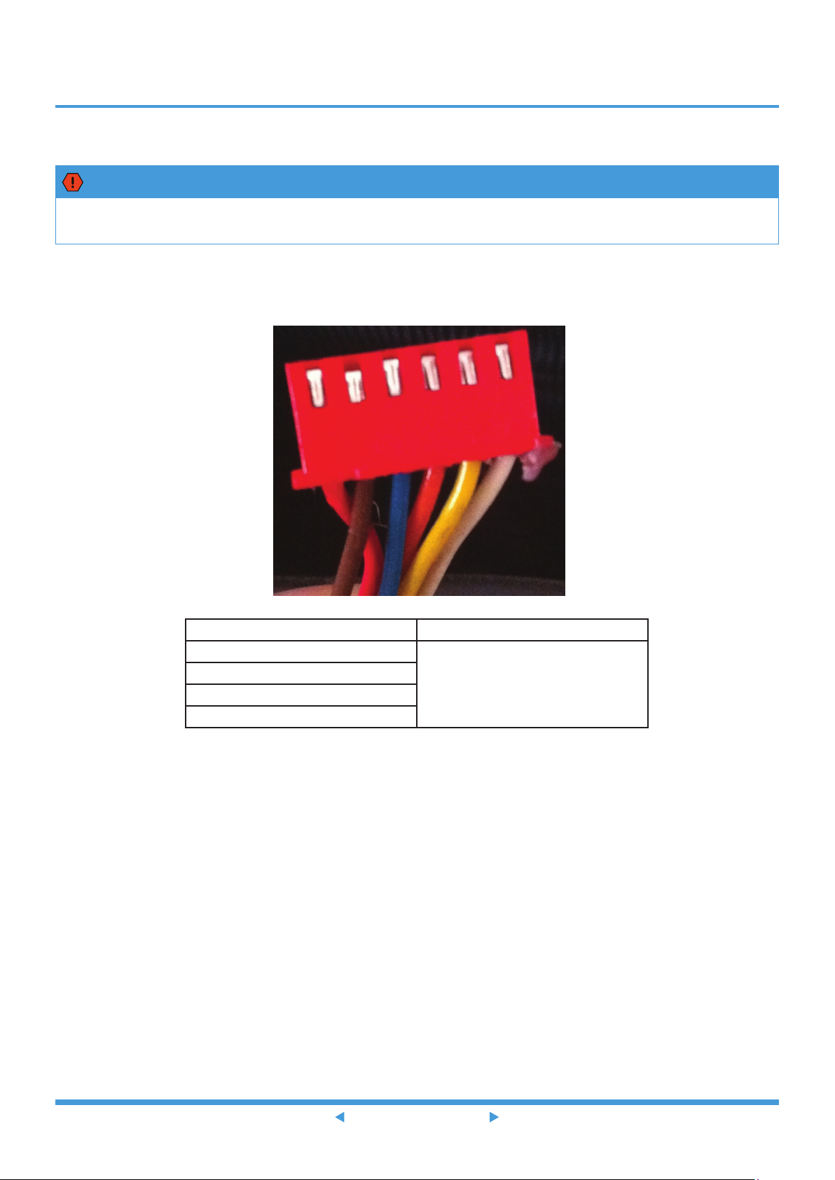
Index:
1. Indoor or Outdoor DC Fan Motor(control chip is in fan motor)
Power on and when the unit is in standby, measure the voltage of pin1-pin3, pin4-pin3 in fan motor connector. If the
value of the voltage is not in the range showing in below table, the PCB must has problems and need to be replaced.
• DC motor voltage input and output (voltage: 220-240V~):
No. Color Signal Voltage
1 Red Vs/Vm 280V~380V
2 --- --- ---
3 Black GND 0V
4 White Vcc 14-17.5V
5 Yellow Vsp 0~5.6V
6 Blue FG 14-17.5V
• DC motor voltage input and output (voltage: 115V~):
No. Color Signal Voltage
1 Red Vs/Vm 140V~190V
2 --- --- ---
3 Black GND 0V
4 White Vcc 14-17.5V
5 Yellow Vsp 0~5.6V
6 Blue FG 14-17.5V
2. Outdoor DC Fan Motor (control chip is in outdoor PCB)
Release the UVW connector. Measure the resistance of U-V, U-W, V-W. If the resistance is not equal to each other, the
fan motor must has problems and need to be replaced. otherwise the PCB must has problems and need to be replaced.
Troubleshooting 23
Page 25
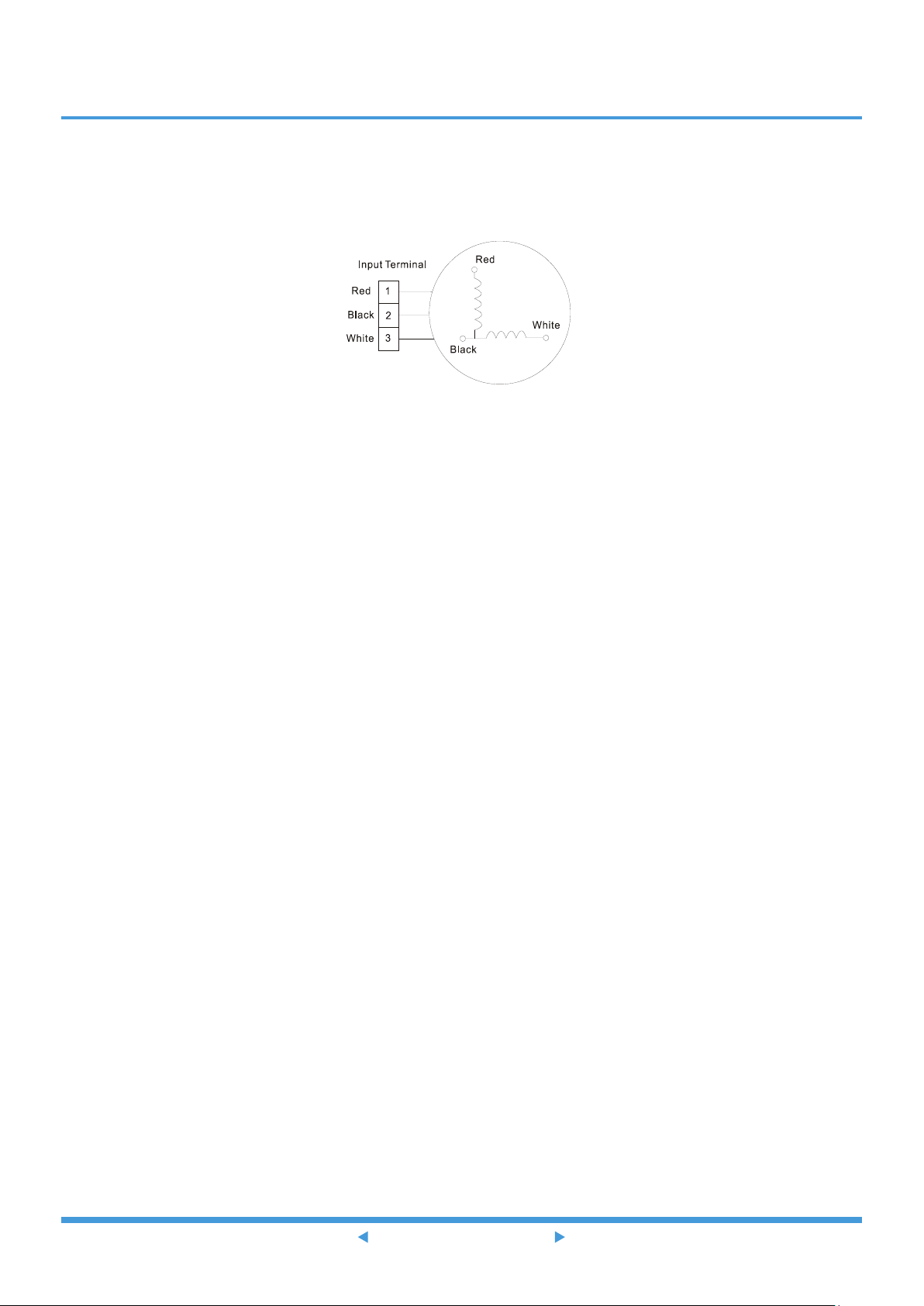
3. Indoor AC Fan Motor
Power on and set the unit running in fan mode at high fan speed. After running for 15 seconds, measure the voltage of
pin1 and pin2. If the value of the voltage is less than 100V(208~240V power supply) or 50V (115V power supply), the
PCB must has problems and need to be replaced.
Troubleshooting 24
Page 26

7.5 EH 60/EH 61/EC 53/EC 52/EC 54/EC 56 (Open circuit or short circuit of temperature
sensor diagnosis and solution)
Description: If the sampling voltage is lower than 0.06V or higher than 4.94V, the LED displays the failure code.
Recommended parts to prepare:
• Connection wires
• Sensors
• PCB
Troubleshooting and repair:
Check the connection between
temperature sensor and PCB.
Is it properly wired? Ensure proper connections.NO
YES
Measure the resistance value
of the sensor.
Is it within acceptable
parameters?
YES
Replace indoor PCB (EH 60/EH 61) or
outdoor PCB (EC 53/EC 52/EC 54/EC 56)
Replace the sensor .NO
Troubleshooting 25
Page 27

Note: For certain models, outdoor PCB could not be removed separately. In this case, the outdoor electric
control box should be replaced as a whole. This picture and the value are only for reference, actual appearance
and value may vary
7.6 EH 0b (Indoor PCB / Display board communication error diagnosis and solution)
Description: Indoor PCB does not receive feedback from the display board.
Recommended parts to prepare:
• Communication wire
• Indoor PCB
• Display board
Troubleshooting and repair:
Power off, then restart the unit 2 minutes
Check the wirings and connections
Are all the connections
Replace the indoor main PCB
later
Is it still displaying
the error code?
YES
?
good
YES
NO
NO
The unit functions normally
Ensure a proper connection
Does the error still exist?
Replace the display board
Troubleshooting 26
Page 28

7.7 EL 0C (Refrigerant Leakage Detection diagnosis and solution)
Description: Define the evaporator coil temperature T2 of the compressor just starts running as Tcool.
In the beginning 5 minutes after the compressor starts up, if T2< Tcool-1°C(1.8°F) does not keep continuous 4 seconds
and compressor running frequency higher than 50Hz does not keep for 3 minutes, and this situation happens 3 times,
the LED displays the failure code and AC turns off.
Recommended parts to prepare:
• T2 sensor
• Indoor PCB
• Additional refrigerant
Troubleshooting and repair:
Power off, then restart the unit 2 minutes later.
Does a problem remain?
YES
Put your hands in front of the
indoor air outlet.
Is there cool
air blowing out from
indoor air outlet?
NO
Check system for leakages.
NO
Are any leakages
present?
NO
Check System for blockages and
clear blockages if present.
YES
YES
Check the T2 sensor.
Is it securely
attached?
Repair the leakage and
recharge the refrigerant.
YES
Replace the
indoor PCB
Troubleshooting 27
Page 29

7.8 PC 08 (Overload current protection diagnosis and solution)
Description: An abnormal current rise is detected by checking the specified current detection circuit.
Recommended parts to prepare:
• Outdoor PCB
• Connection wires
• Compressor
Troubleshooting and repair:
Check the power supply.
Is it in working order?
YES
Check system for blockages.
Do any exist?
No
Check the compressor resistance values.
Are they within acceptable
parameters?
YES
Check the connections and wires.
Are they properly connected ?
YES
Yes
NO
Stop the unit.NO
Clear the blockage.
Replace the compressor.NO
Ensure proper connections or
replace the wires.
Check the reactor.
Is it in working order?
YES
Replace the outdoor unit.
Replace outdoor PCB.NO
Note: For certain models, outdoor PCB could not be removed separately. In this case, the outdoor electric
control box should be replaced as a whole.
Troubleshooting 28
Page 30

7.9 PC 00(IPM malfunction or IGBT over-strong current protection diagnosis and solution)
Description: When the voltage signal the IPM sends to the compressor drive chip is abnormal, the LED displays the
failure code and the AC turns off.
Recommended parts to prepare:
• Connection wires
• IPM module board
• Outdoor fan assembly
• Compressor
• Outdoor PCB
Troubleshooting and repair:
Check the wiring between
PCB and compressor.
Does an error exist?
NO
Check the IPM.
Is it in working order?
YES
Check the outdoor fan and the
outdoor unit ventilation.
Is it in working order?
YES
Check the compressor
resistance values.
YES
NO
NO
Ensure proper connections or
replace the wires and connectors.
Replace the IPM board or
replace the outdoor PCB.
Please refer to the solution of the “Fan
Speed is out of control” malfunction.
Are they within
acceptable parameters?
YES
Replace the outdoor PCB.
NO
Replace the compressor.
Note: For certain models, outdoor PCB could not be removed separately. In this case, the outdoor electric
control box should be replaced as a whole.
Troubleshooting 29
Page 31

7.10 PC 01(Over voltage or too low voltage protection diagnosis and solution)
Description: Abnormal increases or decreases in voltage are detected by checking the specified voltage detection circuit.
Recommended parts to prepare:
• Power supply wires
• IPM module board
• PCB
• Reactor
Troubleshooting and repair:
Check the power supply.
Is it in working order? Turn off the unit.NO
YES
Check the connections and wires.
Are they in working order?
YES
Power on and measure the
voltage between P and N.
While the unit is in standby,
is the voltage between P and N is around
DC 310V, 340V or 380V? When start up
the unit, is it in 220V~400V?
YES
Check the reactor.
Is it in working order? Replace outdoor PCB.
NO
NO
Ensure proper connections or
replace the wires.
Replace the IPM boardNO
YES
Replace the reactor.
Note: For certain models, outdoor PCB could not be removed separately. In this case, the outdoor electric
control box should be replaced as a whole.
Troubleshooting 30
Page 32

7.11 PC 02(High temperature protection of IPM module or High pressure protection
diagnosis and solution)
Description: If the temperature of IPM module is higher than a certain value, the LED displays the failure code.
For some models with high pressure switch, outdoor pressure switch cut off the system because high pressure is higher
than 4.4 MPa, the LED displays the failure code.
Recommended parts to prepare:
• Connection wires
• Outdoor PCB
• IPM module board
• High pressure protector
• System blockages
Troubleshooting and repair:
Check the fastening screws on the
PCB and IPM radiator.
Are they
fixed tightly?
NO
Tighten the screws and apply
silicon grease.
YES
Replace the outdoor
control PCB.
Note: For certain models, outdoor PCB could not be removed separately. In this case, the outdoor electric
control box should be replaced as a whole.
Troubleshooting 31
Page 33

Are the high pressure switch
and main control boar wired
correctly
? Are the high pressure switch
and main control boar wired
correctly
?
Method
:
Disconnect the plug
.
Measure the resistance of the
high pressure protector
,
if the
protector is normal the value is
o, Does a problem still exist
?
No
Is the high pressure
protector broken
?
Is the high pressure
protector broken
?
Is the outdoor ambient
temperature is higher than
50
?
Yes
Check if the outdoor unit
ventilation is good
Yes
Is the heat exchanger dirty
?
Yes
Replace outdoor main board
.
Is
the problem resolved
?
No
High pressure protection
High pressure protection
Is the outdoor fan running
properly
?
NO
Connect high pressure switch and
mian control board
Connect high pressure switch and
main control board
Replace high pressure protector
Replace high pressure protector
Stop the unit
Stop the unit
Ensure that the outdoor unit
Ensure that the outdoor unit
the
“Fan
Speed is
range
”
.
the
“Fan
Speed is
range
”
.
Clean the heat exchanger
Clean the heat exchanger
Check whether the refrigerant
Yes
Method: Disconnect the plug.
Measure the resistance of the
high pressure protector, if the
protector is normal the value is
o, Does a problem still exist?
Yes
Is the outdoor ambient
temperature is higher than
50
?
No
No
Check if the outdoor unit
ventilation is good
Is the outdoor fan running
properly?
Yes
Is the heat exchanger dirty?
No
Replace outdoor main board. Is
the problem resolved?
Check whether the refrigerant
No
Troubleshooting 32
Page 34

7.12 PC 04(Inverter compressor drive error diagnosis and solution)
Description: An abnormal inverter compressor drive is detected by a special detection circuit, including communication
signal detection, voltage detection, compressor rotation speed signal detection and so on.
Recommended parts to prepare:
• Connection wires
• IPM module board
• Outdoor fan assembly
• Compressor
• Outdoor PCB
Troubleshooting and repair:
Check the wiring between the
PCB and compressor.
Is it improperly wired?
NO
Check the IPM.
Is it functioning
properly?
YES
Check the outdoor fan and
the outdoor unit ventilation.
Is it functioning
properly?
YES
Check the compressor
resistance values.
NO
NO
YES
Ensure proper connections or replace
the wires and connectors.
Replace the IPM board or
replace the outdoor PCB.
Please refer to “Fan
Speed Malfunction”
Are they within
acceptable parameters?
YES
Replace the outdoor PCB.
Replace the compressor.NO
Note: For certain models, outdoor PCB could not be removed separately. In this case, the outdoor electric
control box should be replaced as a whole.
Troubleshooting 33
Page 35

7.13 PC 03(Low pressure protection diagnosis and solution)
Description: Outdoor pressure switch cut off the system because low pressure is lower than 0.13 MPa, the LED displays
the failure code.
Recommended parts to prepare:
• Connection wires
• Outdoor PCB
• Low pressure protector
• Refrigerant
Troubleshooting and repair:
Troubleshooting 34
Page 36

Low pressure protection
Low pressure protection
Are the low pressure protector
and main control board wired
properly
?
Are the low pressure protector
and main control board wired
properly
?
Method
:
Disconnect the plug
.
Measure the resistance of the
low pressure protecto
r. I
f the
protector is normal the value is
o. Does a problem still exist
?
Yes
Yes
Replace outdoor main board
.
Does a
problem still exist
?
No
Is the low pressure
protector broken
?
Is the low pressure
protector broken
?
Is the outdoor ambient
temperature
too low
?
No
Is the
valve core of
the
high
p
ressure
valve
fully o
pened
?
Is the
valve core of
the
high
p
ressure
valve
fully o
pened
?
Is the indoor fan running
properly in cooling mode
?
No
Check whether the refrigerant
system is functioning properly
.
Check whether the refrigerant
system is functioning properly
.
When the lvel of refrigerant is not
sufficient
,
doe the system function
properly after more refrigerant is added
No
Reconnect the low pressure protector and main
control board
Reconnect the low pressure protector and main
control board
R
eplace low pressure protector
R
eplace low pressure protector
Open the valve core of the high
pressure valve
Open the valve core of the high
pressure valve
Stop the unit
Stop the unit
Please refer to the solution of
the
“Fan
Speed is
operating outside of normal
range
”
malfunction
.
Method: Disconnect the plug.
Measure the resistance of the
low pressure protector. If the
protector is normal the value is
o. Does a problem still exist?
No
Is the outdoor ambient
temperature too low ?
No
Yes
Is the indoor fan running
properly in cooling mode?
Yes
Replace outdoor main board.. Does a
problem still exist?
When the level of refrigerant is not
sufficient, does the system function
properly after more refrigerant is added?
Yes
No
Please refer to the solution of the “Fan
Speed is operating outside of normal
range
”
malfunction.
Troubleshooting 35
Page 37

8. Check Procedures
8.1 Temperature Sensor Check
WARNING
Be sure to turn off all power supplies or disconnect all wires to avoid electric shock.
Operate after compressor and coil have returned to normal temperature in case of injury.
1. Disconnect the temperature sensor from PCB (Refer to Chapter 5 & 6. Indoor & Outdoor Unit Disassembly).
2. Measure the resistance value of the sensor using a multi-meter.
3. Check corresponding temperature sensor resistance value table (Refer to Chapter 8. Appendix).
Note: The picture and the value are only for reference, actual condition and specific value may vary.
8.2 Compressor Check
1. Disconnect the compressor power cord from outdoor PCB (Refer to Chapter 6. Outdoor Unit Disassembly).
2. Measure the resistance value of each winding using a multi-meter.
3. Check the resistance value of each winding in the following table.
Troubleshooting
Page 38

Resistance Value
Blue-Red
Red-Black
ASM135D23UFZ ATQ420D1UMU ASN98D22UFZ ATF235D22UMT ATQ360D1UMU
1.75Ω 0.37Ω 1.57Ω 0.75Ω 0.37ΩBlue-Black
Resistance Value
Blue-Red
Red-Black
Resistance Value
Blue-Red
Red-Black
Resistance Value
ATM115D43UFZ2 ATF250D22UMT ATF310D43UMT KSK103D33UEZ3(YJ)
ASM98D32UFZ
1.87Ω 0.75Ω 0.65Ω 2.13Ω 2.2ΩBlue-Black
ASN140D21UFZ ASK89D29UEZD KSN140D21UFZ KTM240D57UMT KSK103D33UEZ3
1.28Ω 1.99Ω 1.28Ω 0.62Ω 2.13ΩBlue-Black
KTF310D43UMT KTQ420D1UMU ATN150D30UFZA KTM240D43UKT KTN110D42UFZ
Blue-Red
Red-Black
Resistance Value
Blue-Red
Red-Black
0.65Ω 0.37Ω 1.03Ω 1.03Ω 1.82ΩBlue-Black
KTF250D22UMT KSN140D58UFZ
0.75Ω 1.86ΩBlue-Black
Troubleshooting
Page 39

Note: The picture and the value are only for reference, actual condition and specific value may vary.
8.3 IPM Continuity Check
WARNING
Electricity remains in capacitors even when the power supply is off.
Ensure the capacitors are fully discharged before troubleshooting.
1. Turn off outdoor unit and disconnect power supply.
2. Discharge electrolytic capacitors and ensure all energy-storage unit has been discharged.
3. Disassemble outdoor PCB or disassemble IPM board.
4. Measure the resistance value between P and U (V, W, N); U (V, W) and N.
Digital tester Resistance value Digital tester Resistance value
(+)Red (-)Black
N U
U V
P
V W
W -
∞
(Several MΩ)
Troubleshooting
(+)Red (-)Black
N
∞
(Several MΩ)
Page 40

Note: The picture and the value are only for reference, actual condition and specific value may vary.
Troubleshooting
Page 41

8.4 4-way Valve Check
1. Power on, use a digital tester to measure the voltage, when the unit operates in cooling, it is 0V. When the unit
operates in heating, it is about 230VAC.
If the value of the voltage is not in the range, the PCB must have problems and need to be replaced.
2 Turn off the power, use a digital tester to measure the resistance. The value should be 1.8~2.5 KΩ.
Troubleshooting
Page 42
8.5 EXV Check
WARNING
Electricity remains in capacitors even when the power supply is off.
Ensure the capacitors are fully discharged before troubleshooting.
1. Disconnect the connector from outdoor PCB.
2. Measure the resistance value of each winding using a multi-meter.
3. Check the resistance value of each winding in the following table.
6 5 4 3 2 1
Red Brown Blue Orange Yellow White
Color of lead winding Normal Value
Red- Blue
Red - Yellow
Brown-Orange
Brown-White
About 50Ω
Troubleshooting
Page 43

Appendix
Contents
i) Temperature Sensor Resistance Value Table for T1, T2, T3, and T4 (°C – K) ......2
ii) Temperature Sensor Resistance Value Table for TP (for some units) (°C --K) ....3
iii) Pressure On Service Port .......................................................................................4
Page 44

i) Temperature Sensor Resistance Value Table for T1,T2,T3 and T4 (°C – K)
°C °F K Ohm °C °F K Ohm °C °F K Ohm °C °F K Ohm
-20 -4 115.266 20 68 12.6431 60 140 2.35774 100 212 0.62973
-19 -2 108.146 21 70 12.0561 61 142 2.27249 101 214 0.61148
-18 0 101.517 22 72 11.5 62 144 2.19073 102 216 0.59386
-17 1 96.3423 23 73 10.9731 63 145 2.11241 103 217 0.57683
-16 3 89.5865 24 75 10.4736 64 147 2.03732 104 219 0.56038
-15 5 84.219 25 77 10 65 149 1.96532 105 221 0.54448
-14 7 79.311 26 79 9.55074 66 151 1.89627 106 223 0.52912
-13 9 74.536 27 81 9.12445 67 153 1.83003 107 225 0.51426
-12 10 70.1698 28 82 8.71983 68 154 1.76647 108 226 0.49989
-11 12 66.0898 29 84 8.33566 69 156 1.70547 109 228 0.486
-10 14 62.2756 30 86 7.97078 70 158 1.64691 110 230 0.47256
-9 16 58.7079 31 88 7.62411 71 160 1.59068 111 232 0.45957
-8 18 56.3694 32 90 7.29464 72 162 1.53668 112 234 0.44699
-7 19 52.2438 33 91 6.98142 73 163 1.48481 113 235 0.43482
-6 21 49.3161 34 93 6.68355 74 165 1.43498 114 237 0.42304
-5 23 46.5725 35 95 6.40021 75 167 1.38703 115 239 0.41164
-4 25 44 36 97 6.13059 76 169 1.34105 116 241 0.4006
-3 27 41.5878 37 99 5.87359 77 171 1.29078 117 243 0.38991
-2 28 39.8239 38 100 5.62961 78 172 1.25423 118 244 0.37956
-1 30 37.1988 39 102 5.39689 79 174 1.2133 119 246 0.36954
0 32 35.2024 40 104 5.17519 80 176 1.17393 120 248 0.35982
1 34 33.3269 41 106 4.96392 81 178 1.13604 121 250 0.35042
2 36 31.5635 42 108 4.76253 82 180 1.09958 122 252 0.3413
3 37 29.9058 43 109 4.5705 83 181 1.06448 123 253 0.33246
4 39 28.3459 44 111 4.38736 84 183 1.03069 124 255 0.3239
5 41 26.8778 45 113 4.21263 85 185 0.99815 125 257 0.31559
6 43 25.4954 46 115 4.04589 86 187 0.96681 126 259 0.30754
7 45 24.1932 47 117 3.88673 87 189 0.93662 127 261 0.29974
8 46 22.5662 48 118 3.73476 88 190 0.90753 128 262 0.29216
9 48 21.8094 49 120 3.58962 89 192 0.8795 129 264 0.28482
10 50 20.7184 50 122 3.45097 90 194 0.85248 130 266 0.2777
11 52 19.6891 51 124 3.31847 91 196 0.82643 131 268 0.27078
12 54 18.7177 52
13 55 17.8005 53 127 3.07075 93 199 0.77709 133 271 0.25757
14 57 16.9341 54 129 2.95896 94 201 0.75373 134 273 0.25125
15 59 16.1156 55 131 2.84421 95 203 0.73119 135 275 0.24512
16 61 15.3418 56 133 2.73823 96 205 0.70944 136 277 0.23916
17 63 14.6181 57 135 2.63682 97 207 0.68844 137 279 0.23338
18 64 13.918 58 136 2.53973 98 208 0.66818 138 280 0.22776
19 66 13.2631 59 138 2.44677 99 210 0.64862 139 282 0.22231
126 3.19183 92 198 0.80132 132 270 0.26408
Appendix 2
Page 45

ii) Temperature Sensor Resistance Value Table for TP (for some units) (°C --K)
°C °F K Ohm °C °F K Ohm °C °F K Ohm °C °F K Ohm
°C °F K Ohm °C °F K Ohm °C °F K Ohm °C °F K Ohm
-20 -4 542.7 20 68 68.66 60 140 13.59 100 212 3.702
-19 -2 511.9 21 70 65.62 61 142 13.11 101 214 3.595
-18 0 483 22 72 62.73 62 144 12.65 102 216 3.492
-17 1 455.9 23 73 59.98 63 145 12.21 103 217 3.392
-16 3 430.5 24 75 57.37 64 147 11.79 104 219 3.296
-15 5 406.7 25 77 54.89 65 149 11.38 105 221 3.203
-14 7 384.3 26 79 52.53 66 151 10.99 106 223 3.113
-13 9 363.3 27 81 50.28 67 153 10.61 107 225 3.025
-12 10 343.6 28 82 48.14 68 154 10.25 108 226 2.941
-11 12 325.1 29 84 46.11 69 156 9.902 109 228 2.86
-10 14 307.7 30 86 44.17 70 158 9.569 110 230 2.781
-9 16 291.3 31 88 42.33 71 160 9.248 111 232 2.704
-8 18 275.9 32 90 40.57 72 162 8.94 112 234 2.63
-7 19 261.4 33 91 38.89 73 163 8.643 113 235 2.559
-6 21 247.8 34 93 37.3 74 165 8.358 114 237 2.489
-5 23 234.9 35 95 35.78 75 167 8.084 115 239 2.422
-4 25 222.8 36 97 34.32 76 169 7.82 116 241 2.357
-3 27 211.4 37 99 32.94 77 171 7.566 117 243 2.294
-2 28 200.7 38 100 31.62 78 172 7.321 118 244 2.233
-1 30 190.5 39 102 30.36 79 174 7.086 119 246 2.174
0 32 180.9 40 104 29.15 80 176 6.859 120 248 2.117
1 34 171.9 41 106 28 81 178 6.641 121 250 2.061
2 36 163.3 42 108 26.9 82 180 6.43 122 252 2.007
3 37 155.2 43 109 25.86 83 181 6.228 123 253 1.955
4 39 147.6 44 111 24.85 84 183 6.033 124 255 1.905
5 41 140.4 45 113 23.89 85 185 5.844 125 257 1.856
6 43 133.5 46 115 22.89 86 187 5.663 126 259 1.808
7 45 127.1 47 117 22.1 87 189 5.488 127 261 1.762
8 46 121 48 118 21.26 88 190 5.32 128 262 1.717
9 48 115.2 49 120 20.46 89 192 5.157 129 264 1.674
10 50 109.8 50 122 19.69 90 194 5 130 266 1.632
11 52 104.6 51
12 54 99.69 52 126 18.26 92 198 4.703
13 55 95.05 53 127 17.58 93 199 4.562
14 57 90.66 54 129 16.94 94 201 4.426
15 59 86.49 55 131 16.32 95 203 4.294
16 61 82.54 56 133 15.73 96 205 4.167
17 63 78.79 57 135 15.16 97 207 4.045
18 64 75.24 58 136 14.62 98 208 3.927
19 66 71.86 59 138 14.09 99 210 3.812
124 18.96 91 196 4.849
Appendix 3
Page 46

iii) Pressure On Service Port
Cooling chart (R410A):
°F(°C)
BAR
PSI
MPa
ODU(DB)
0(-17) 5(-15)
IDU(DB/WB)
70/59 (21.11/15) 6.4 6.5 7.3 8.0 8.2 7.8 8.1 8.6 10.1 10.6
75/63 (23.89/17.22) 6.7 6.8 7.9 8.6 8.6 8.3 8.7 9.1 10.7 11.2
80/67 (26.67/19.44) 7.1 7.2 8.5 9.5 9.3 8.9 9.1 9.6 11.2 11.9
90/73 (32.22/22.78) 7.7 7.8 9.6 10.5 10.3 9.5 10.0 10.6 12.4 13.0
70/59 (21.11/15) 93 94 106 116 119 113 117 125 147 154
75/63 (23.89/17.22) 97 99 115 125 124 120 126 132 155 162
80/67 (26.67/19.44) 103 104 123 138 135 129 132 140 162 173
90/73 (32.22/22.78) 112 113 139 152 149 138 145 154 180 189
70/59 (21.11/15) 0.64 0.65 0.73 0.8 0.82 0.78 0.81 0.86 1.01 1.06
75/63 (23.89/17.22) 0.67 0.68 0.79 0.86 0.86 0.83 0.87 0.91 1.07 1.12
80/67 (26.67/19.44) 0.71 0.72 0.85 0.95 0.93 0.89 0.91 0.96 1.12 1.19
90/73 (32.22/22.78) 0.77 0.78 0.96 1.05 1.03 0.95 1 1.06 1.24 1.3
15
(-9.44)
45
(7.22)
75
(23.89)
85
(29.44)
95 (35)
105
(40.56)
115
(46.11)
120
(48.89)
1.4
1.2
0.8
0.6
0.4
0.2
1
70/59
75/63
80/67
90/73
0
Appendix 4
Page 47

Heating chart (R410A):
°F(°C)
BAR
PSI
MPa
ODU(DB/WB)
IDU(DB)
55(12.78) 30.3 28.5 25.3 22.8 20.8 18.5 16.5
65(18.33) 32.5 30.0 26.6 25.4 23.3 20.5 19.0
75(23.89) 33.8 31.5 27.8 26.3 24.9 21.5 20.0
55(12.78) 439 413 367 330 302 268 239
65(18.33) 471 435 386 368 339 297 276
75(23.89) 489 457 403 381 362 312 290
55(12.78) 3.03 2.85 2.53 2.28 2.08 1.85 1.65
65(18.33) 3.25 3.00 2.66 2.54 2.33 2.05 1.90
75(23.89) 3.38 3.15 2.78 2.63 2.49 2.15 2.00
57/53
(13.89/11.67)
47/43
(8.33/6.11)
37/33
(2.78/0.56)
27/23
(-2.78/-5)
17/13 (-8.33/-
10.56)
0/-2
(-17/-19)
4
3.5
3
2.5
2
-17/-18
(-27/-28)
1.5
0.5
55
1
65
75
0
Appendix 5
Page 48

Cooling chart (R22):
°F(°C)
BAR
PSI
MPa
ODU(DB)
0(-17) 5(-15)
IDU(DB/WB)
70/59 (21.11/15) 4.0 4.1 4.6 5.0 5.1 4.9 5.1 5.4 6.3 6.6
75/63 (23.89/17.22) 4.2 4.3 4.9 5.4 5.4 5.2 5.4 5.7 6.7 7.0
80/67 (26.67/19.44) 4.4 4.5 5.3 5.9 5.8 5.6 5.7 6.0 7.0 7.4
90/73 (32.22/22.78) 4.8 4.9 6.0 6.6 6.4 5.9 6.3 6.6 7.8 8.1
70/59 (21.11/15) 58 59 67 73 74 71 74 78 91 96
75/63 (23.89/17.22) 61 62 71 78 78 75 78 83 97 102
80/67 (26.67/19.44) 64 65 77 86 84 81 83 87 102 107
90/73 (32.22/22.78) 70 71 87 96 93 86 91 96 113 117
70/59 (21.11/15) 0.40 0.41 0.46 0.50 0.51 0.49 0.51 0.54 0.63 0.66
75/63 (23.89/17.22) 0.42 0.43 0.49 0.54 0.54 0.52 0.54 0.57 0.67 0.70
80/67 (26.67/19.44) 0.44 0.45 0.53 0.59 0.58 0.56 0.57 0.60 0.70 0.74
90/73 (32.22/22.78) 0.48 0.49 0.60 0.66 0.64 0.59 0.63 0.66 0.78 0.81
15
(-9.44)
45
(7.22)
75
(23.89)
85
(29.44)
95 (35)
105
(40.56)
115
(46.11)
120
(48.89)
0.9
0.8
0.7
0.6
0.5
0.4
0.3
0.2
0.1
70/59
75/63
80/67
90/73
0
Appendix 6
Page 49

Heating chart (R22):
°F(°C)
BAR
PSI
MPa
ODU(DB/WB)
IDU(DB)
55(12.78) 18.9 17.8 15.8 14.3 13.0 11.6 10.3
65(18.33) 20.3 18.8 16.6 15.9 14.6 12.8 11.9
75(23.89) 21.1 19.7 17.3 16.4 15.6 13.4 12.5
55(12.78) 274 258 229 207 189 168 149
65(18.33) 294 273 241 231 212 186 172.6
75(23.89) 306 286 251 238 226 194 181
55(12.78) 1.89 1.78 1.58 1.43 1.30 1.16 1.03
65(18.33) 2.03 1.88 1.66 1.59 1.46 1.28 1.19
75(23.89) 2.11 1.97 1.73 1.64 1.56 1.34 1.25
57/53
(13.89/11.67)
47/43
(8.33/6.11)
37/33
(2.78/0.56)
27/23
(-2.78/-5)
17/13 (-8.33/-
10.56)
0/-2
(-17/-19)
2.5
2
1.5
-17/-18
(-27/-28)
0.5
1
55
65
75
0
Appendix 7
Page 50

Cooling chart (R32):
°F(°C)
BAR
PSI
MPa
ODU(DB)
0(-17) 5(-15)
IDU(DB/WB)
70/59 (21.11/15) 6.5 6.6 7.4 8.2 8.4 8.0 8.3 8.8 10.3 10.8
75/63 (23.89/17.22) 6.8 6.9 8.1 8.8 8.8 8.5 8.9 9.3 10.9 11.4
80/67 (26.67/19.44) 7.2 7.3 8.7 9.7 9.5 9.1 9.3 9.8 11.4 12.1
90/73 (32.22/22.78) 7.9 8.0 9.8 10.7 10.5 9.7 10.2 10.8 12.6 13.3
70/59 (21.11/15) 95 96 108 118 121 115 119 128 150 157
75/63 (23.89/17.22) 99 101 117 128 126 122 129 135 158 165
80/67 (26.67/19.44) 105 106 125 141 138 132 135 143 165 176
90/73 (32.22/22.78) 114 115 142 155 152 141 148 157 184 193
70/59 (21.11/15) 0.65 0.66 0.74 0.82 0.84 0.80 0.83 0.88 1.03 1.08
75/63 (23.89/17.22) 0.68 0.69 0.81 0.88 0.88 0.85 0.89 0.93 1.09 1.14
80/67 (26.67/19.44) 0.72 0.73 0.87 0.97 0.95 0.91 0.93 0.98 1.14 1.21
90/73 (32.22/22.78) 0.79 0.80 0.98 1.07 1.05 0.97 1.02 1.08 1.26 1.33
15
(-9.44)
45
(7.22)
75
(23.89)
85
(29.44)
95 (35)
105
(40.56)
115
(46.11)
1.4
1.2
120
(48.89)
0.8
0.6
0.4
0.2
1
70/59
75/63
80/67
90/73
0
Appendix 8
Page 51

Heating chart (R32):
°F(°C)
BAR
PSI
MPa
ODU(DB/WB)
IDU(DB)
55(12.78) 30.9 29.1 25.8 23.3 21.2 18.9 16.8
65(18.33) 33.2 30.6 27.1 25.9 23.8 20.9 19.4
75(23.89) 34.5 32.1 28.4 26.8 25.4 21.9 20.4
55(12.78) 448 421 374 337 308 273 244
65(18.33) 480 444 394 375 346 303 282
75(23.89) 499 466 411 389 369 318 296
55(12.78) 3.09 2.91 2.58 2.33 2.12 1.89 1.68
65(18.33) 3.32 3.06 2.71 2.59 2.38 2.09 1.94
75(23.89) 3.45 3.21 2.84 2.68 2.54 2.19 2.04
57/53
(13.89/11.67)
47/43
(8.33/6.11)
37/33
(2.78/0.56)
27/23
(-2.78/-5)
17/13 (-8.33/-
10.56)
0/-2
(-17/-19)
4
3.5
3
2.5
2
-17/-18
(-27/-28)
1.5
0.5
55
1
65
75
0
Appendix 9
Page 52

System Pressure Table-R22
Pressure Temperature Pressure Temperature
Kpa bar PSI °C °F Kpa bar PSI °C °F
100 1 14.5 -41.091 -41.964 1600 16 232 41.748 107.146
150 1.5 21.75 -32.077 -25.739 1650 16.5 239.25 43.029 109.452
200 2 29 -25.177 -13.319 1700 17 246.5 44.281 111.706
250 2.5 36.25 -19.508 -3.114 1750 17.5 253.75 45.506 113.911
300 3 43.5 -14.654 5.623 1800 18 261 46.706 116.071
350 3.5 50.75 -10.384 13.309 1850 18.5 268.25 47.882 118.188
400 4 58 -6.556 20.199 1900 19 275.5 49.034 120.261
450 4.5 65.25 -3.075 26.464 1950 19.5 282.75 50.164 122.295
500 5 72.5 0.124 32.223 2000 20 290 51.273 124.291
550 5.5 79.75 3.091 37.563 2050 20.5 297.25 52.361 126.250
600 6 87 5.861 42.550 2100 21 304.5 53.43 128.174
650 6.5 94.25 8.464 47.234 2150 21.5 311.75 54.48 130.064
700 7 101.5 10.92 51.656 2200 22 319 55.512 131.922
750 7.5 108.75 13.249 55.848 2250 22.5 326.25 56.527 133.749
800 8 116 15.465 59.837 2300 23 333.5 57.526 135.547
850 8.5 123.25 17.58 63.644 2350 23.5 340.75 58.508 137.314
900 9 130.5 19.604 67.287 2400 24 348 59.475 139.055
950 9.5 137.75 21.547 70.785 2450 24.5 355.25 60.427 140.769
1000 10 145 23.415 74.147 2500 25 362.5 61.364 142.455
1050 10.5 152.25 25.216 77.389 2550 25.5 369.75 62.288 144.118
1100 11 159.5 26.953 80.515 2600 26 377 63.198 145.756
1150 11.5 166.75 28.634 83.541 2650 26.5 384.25 64.095 147.371
1200 12 174 30.261 86.470 2700 27 391.5 64.98 148.964
1250 12.5 181.25 31.839 89.310 2750 27.5 398.75 65.852 150.534
1300 13 188.5 33.371 92.068 2800 28 406 66.712 152.082
1350 13.5 195.75 34.86 94.748 2850 28.5 413.25 67.561 153.610
1400 14 203 36.308 97.354 2900 29 420.5 68.399 155.118
1450 14.5 210.25 37.719 99.894 2950 29.5 427.75 69.226 156.607
1500 15 217.5 39.095 102.371 3000 30 435 70.042 158.076
1550 15.5 224.75 40.437 104.787
Appendix 10
Page 53

System Pressure Table-R410A
Pressure Temperature Pressure Temperature
Kpa bar PSI °C °F Kpa bar PSI °C °F
100 1 14.5 -51.623 -60.921 2350 23.5 340.75 38.817 101.871
150 1.5 21.75 -43.327 -45.989 2400 24 348 39.68 103.424
200 2 29 -36.992 -34.586 2450 24.5 355.25 40.531 104.956
250 2.5 36.25 -31.795 -25.231 2500 25 362.5 41.368 106.462
300 3 43.5 -27.351 -17.232 2550 25.5 369.75 42.192 107.946
350 3.5 50.75 -23.448 -10.206 2600 26 377 43.004 109.407
400 4 58 -19.953 -3.915 2650 26.5 384.25 43.804 110.847
450 4.5 65.25 -16.779 1.798 2700 27 391.5 44.592 112.266
500 5 72.5 -13.863 7.047 2750 27.5 398.75 45.37 113.666
550 5.5 79.75 -11.162 11.908 2800 28 406 46.136 115.045
600 6 87 -8.643 16.444 2850 28.5 413.25 46.892 116.406
650 6.5 94.25 -6.277 20.701 2900 29 420.5 47.638 117.748
700 7 101.5 -4.046 24.716 2950 29.5 427.75 48.374 119.073
750 7.5 108.75 -1.933 28.521 3000 30 435 49.101 120.382
800 8 116 0.076 32.137 3050 30.5 442.25 49.818 121.672
850 8.5 123.25 1.993 35.587 3100 31 449.5 50.525 122.945
900 9 130.5 3.826 38.888 3150 31.5 456.75 51.224 124.203
950 9.5 137.75 5.584 42.052 3200 32 464 51.914 125.445
1000 10 145 7.274 45.093 3250 32.5 471.25 52.596 126.673
1050 10.5 152.25 8.901 48.022 3300 33 478.5 53.27 127.886
1100 11 159.5 10.471 50.848 3350 33.5 485.75 53.935 129.083
1150 11.5 166.75 11.988 53.578 3400 34 493 54.593 130.267
1200 12 174 13.457 56.223 3450 34.5 500.25 55.243 131.437
1250 12.5 181.25 14.879 58.782 3500 35 507.5 55.885 132.593
1300 13 188.5 16.26 61.268 3550 35.5 514.75 56.52 133.736
1350 13.5 195.75 17.602 63.684 3600 36 522 57.148 134.866
1400 14 203 18.906 66.031 3650 36.5 529.25 57.769 135.984
1450 14.5 210.25 20.176 68.317 3700 37 536.5 58.383 137.089
1500 15 217.5 21.414 70.545 3750 37.5 543.75 58.99 138.182
1550 15.5 224.75 22.621 72.718 3800 38 551 59.591 139.264
1600 16 232 23.799 74.838 3850 38.5 558.25 60.185 140.333
1650 16.5 239.25 24.949 76.908 3900 39 565.5 60.773 141.391
1700 17 246.5 26.074 78.933 3950 39.5 572.75 61.355 142.439
1750 17.5 253.75 27.174 80.913 4000 40 580 61.93 143.474
1800 18 261 28.251 82.852 4050 40.5 587.25 62.499 144.498
1850 18.5 268.25 29.305 84.749 4100 41 594.5 63.063 145.513
1900 19 275.5 30.338 86.608 4150 41.5 601.75 63.62 146.516
1950 19.5 282.75 31.351 88.432 4200 42 609 64.172 147.510
2000 20 290 32.344 90.219 4250 42.5 616.25 64.719 148.494
2050 20.5 297.25 33.319 91.974 4300 43 623.5 65.259 149.466
2100 21 304.5 34.276 93.697 4350 43.5 630.75 65.795 150.431
2150 21.5 311.75 35.215 95.387 4400 44 638 66.324 151.383
2200 22 319 36.139 97.050 4450 44.5 645.25 66.849 152.328
2250 22.5 326.25 37.047 98.685 4500 45 652.5 67.368 153.262
2300 23 333.5 37.939 100.290
Appendix 11
Page 54

System Pressure Table-R32
Pressure Temperature Pressure Temperature
Kpa bar PSI °C °F Kpa bar PSI °C °F
100 1 14.5 -51.909 -61.436 1850 18.5 268.25 28.425 83.165
150 1.5 21.75 -43.635 -46.543 1900 19 275.5 29.447 85.005
200 2 29 -37.323 -35.181 1950 19.5 282.75 30.448 86.806
250 2.5 36.25 -32.15 -25.87 2000 20 290 31.431 88.576
300 3 43.5 -27.731 -17.916 2050 20.5 297.25 32.395 90.311
350 3.5 50.75 -23.85 -10.93 2100 21 304.5 33.341 92.014
400 4 58 -20.378 -4.680 2150 21.5 311.75 34.271 93.688
450 4.5 65.25 -17.225 0.995 2200 22 319 35.184 95.331
500 5 72.5 -14.331 6.204 2250 22.5 326.25 36.082 96.948
550 5.5 79.75 -11.65 11.03 2300 23 333.5 36.965 98.537
600 6 87 -9.150 15.529 2350 23.5 340.75 37.834 100.101
650 6.5 94.25 -6.805 19.752 2400 24 348 38.688 101.638
700 7 101.5 -4.593 23.734 2450 24.5 355.25 39.529 103.152
750 7.5 108.75 -2.498 27.505 2500 25 362.5 40.358 104.644
800 8 116 -0.506 31.089 2550 25.5 369.75 41.173 106.111
850 8.5 123.25 1.393 34.507 2600 26 377 41.977 107.559
900 9 130.5 3.209 37.777 2650 26.5 384.25 42.769 108.984
950 9.5 137.75 4.951 40.911 2700 27 391.5 43.55 110.39
1000 10 145 6.624 43.923 2750 27.5 398.75 44.32 111.776
1050 10.5 152.25 8.235 46.823 2800 28 406 45.079 113.142
1100 11 159.5 9.790 49.621 2850 28.5 413.25 45.828 114.490
1150 11.5 166.75 11.291 52.324 2900 29 420.5 46.567 115.821
1200 12 174 12.745 54.941 2950 29.5 427.75 47.296 117.133
1250 12.5 181.25 14.153 57.475 3000 30 435 48.015 118.427
1300 13 188.5 15.52 59.936 3050 30.5 442.25 48.726 119.707
1350 13.5 195.75 16.847 62.325 3100 31 449.5 49.428 120.970
1400 14 203 18.138 64.648 3150 31.5 456.75 50.121 122.218
1450 14.5 210.25 19.395 66.911 3200 32 464 50.806 123.451
1500 15 217.5 20.619 69.114 3250 32.5 471.25 51.482 124.668
1550 15.5 224.75 21.813 71.263 3300 33 478.5 52.15 125.87
1600 16 232 22.978 73.360 3350 33.5 485.75 52.811 127.060
1650 16.5 239.25 24.116 75.409 3400 34 493 53.464 128.235
1700 17 246.5 25.229 77.412 3450 34.5 500.25 54.11 129.398
1750 17.5 253.75 26.317 79.371 3500 35 507.5 54.748 130.546
1800 18 261 27.382 81.288
Appendix 12
Page 55

4th Generation
®
DIY
E Star™
Series
 Loading...