

Page 1

Please read this manual carefully before installation and keep it for future reference.
For more info visit www.mrcool.com
Installation Manual
Olympus Series
Cassette Air Handlers
Please keep this manual where the operator can easily find it.
Inside you will find helpful hints on how to use and maintain your
unit properly.
Page 2

If used as MULTI unit, please refer to the Installation & operation manuals packed with outdoor unit.
For more info visit www.mrcool.com
Page 3
CONTENTS Page
For more info visit www.mrcool.com
PRECAUTIONS
INSTALLATION INFORMATION
ACCESSORIES
INDOOR UNIT INSTALLATION
OUTDOOR UNIT INSTALLATION
INSTALL THE REFRIGERANT PIPE
CONNECT THE DRAIN PIPE
ELECTRIC WIRING WORK
INSTALLATION OF THE DECORATION PANEL
TEST OPERATION
...................................................................................1
..........................................................2
...................................................................................3
...........................................................4
.......................................................7
...................................................9
............................................................12
...............................................................13
...............................15
............................................................................16
PRECAUTIONS
Install according to this installation instructions strictly.
If installation is defective, it will cause water leakage, electrical
shock and fire.
When installing the unit in a small room, take measures
against to keep refrigerant concentration from exceeding
allowable safety limits in the event of refrigerant leakage.
Contact the place of purchase for more information. Excessive
refrigerant in a closed ambient can lead to oxygen deficiency.
Use the attached accessories parts and specified parts for
installation.
otherwise, it will cause the set to fall, water leakage, electrical
shock and fire.
Install at a strong and firm location which is able to withstand
the set' s weight.
If the strength is not enough or installation is not properly done,
the set will drop to cause injury.
The appliance must be installed 8.2ft / 2.5m above floor.
Keep this manual where the operator can easily find them.
Read this manual attentively before starting up the units.
For safety reason the operator must read the following
cautions carefully.
Installation must be performed in accordance with the
requirement of NEC and CEC by authorized personnel only.
The safty precautions listed here are divided into two categories.
WARNING
If you do not follow these instrutions exactly, the unit may
cause property damage, personal injury or loss of life.
CAUTION
If you do not follow these instrutions exactly, the unit may
cause minor or moderate property damage, personal injury.
After completing the installation, make sure that the unit operates
properly during the start-up operation. Please instruct the customer on
how to operate the unit and keep it maintained.
that they should store this installation manual along with the owner's
manual for future reference.
Also, inform customers
The appliance shall not be installed in the laundry.
Before obtaining access to terminals, all supply circuits must
be disconnected.
The appliance must be positioned so that the plug is accessible.
The enclosure of the appliance shall be marked by word, or by
symbols, with the direction of the fluid flow.
For electrical work, follow the local national wiring standard,
regulation and this installation instructions. An independent
circuit and single outlet must be used.
If electrical circuit capacity is not enough or defect in electrical
work, it will cause electrical shock or fire.
Use the specified cable and connect tightly and clamp the
cable so that no external force will be acted on the terminal.
If connection or fixing is not perfect, it will cause heat-up or fire
at the connection.
Wiring routing must be properly arranged so that control board
cover is fixed properly.
If control board cover is not fixed perfectly, it will cause heat-up
at connection point of terminal, fire or electrical shock.
If the supply cord is damaged, it must be replaced by the
manufacture or its service agent or a similarly qualified person
in order to avoid a hazard.
An all-pole disconnection switch having a contact separation
of at least
0.12in in all poles should be connected in fixed wiring.
WARNING
Be sure only trained and qualified service personnel install,
repair or service the equipment.
Improper installation, repair, and maintenance may result in
electric shocks, short-circuit, leaks, fire or other damage to the
equipment.
When carrying out piping connection, take care not to let air
substances go into refrigeration cycle.
Otherwise, it will cause lower capacity, abnormal high pressure
in the refrigeration cycle, explosion and injury.
Do not modify the length of the power supply cord or use of
extension cord, and do not share the single outlet with other
electrical appliances.
Otherwise, it will cause fire or electrical shock.
1
Page 4
If the refrigerant leaks during installation, ventilate the area
For more info visit www.mrcool.com
immediately.
Toxic gas may be produced if the refrigerant comes into the
place contacting with fire.
The temperature of refrigerant circuit will be high, please keep
the interconnection cable away from the copper tube.
After completing the installation work, check that the refrigerant
does not leak.
Toxic gas may be produced if the refrigerant leaks into the
room and comes into contact with a source of fire, such as a
fan heater, stove or cooker.
CAUTION
Ground the air conditioner.
Do not connect the ground wire to gas or water pipes, lightning
rod or a telephone ground wire. Inappropriate grounding may
result in electric shocks.
Be sure to install an earth leakage breaker.
Failure to install an earth leakage breaker may result in electric
shocks.
Connect the outdoor unit wires, then connect the indoor unit
wires.
You are not allowed to connect the air conditioner with the
power supply until the wiring and piping is done.
While following the instructions in this installation manual, install
drain piping in order to ensure proper drainage and insulate
piping in order to prevent condensation.
Improper drain piping may result in water leakage and property
damage.
There are inflammable
There is acid
Other special conditions.
The appliance shall be installed in accordance with national
wiring regulations.
Do not operate your air conditioner in a wet room such as a
bathroom or laundry room.
An all-pole disconnection device which has at least 0.1in / 3mm
clearances in all poles, and have a leakage current that may
exceed 10mA, the residual current device (RCD) having a rated
residual operating current not exceeding 30mA, and
disconnection must be incorporated in the fixed wiring in
accordance with the wiring rules.
or alkaline liquid
materials or gas.
evaporating.
INSTALLATION INFORMATION
To install properly, please read this "installation manual" at
first.
The air conditioner must be installed by qualified persons.
When installing the indoor unit or its tubing, please follow
this manual as strictly as possible.
If the air conditioner is installed on a metal part of the
building, it must be electrically insulated according to the
relevant standards to electrical appliances.
Install the indoor and outdoor units, power supply wiring and
connecting wires should be at least 3.3ft
televisions or radios in order to prevent image interference or
noise.
Depending on the radio waves, a distance of 3.3ft
be sufficient enough to eliminate the noise.
The appliance is not intended for use by young children or
infirm persons without supervision.
Don't install the air conditioner in the following circumstance:
There is petrolatum existing.
There is salty
There is caustic
in the air
The Volt
In buses or
In kitchen where
There is strong
air surrounding (near the coast).
gas (the sulfide,
(near a hot
vibrates violently (in
cabinets.
spring).
of oil gas.
it is full
electromagnetic wave existing.
away from
may not
for example) existing
the factories).
When all the installation work is finished, please turn on
the power only after a thorough check.
Regret for no further announcement if there is any change
of this manual caused by product improvement.
INSTALLATION ORDER
Indoor unit installation;
Outdoor unit installation;
Install the refrigerant pipe;
Connect the drain pipe;
Electric wiring work;
Installation of the decoration panel;
Test operation.
2
Page 5
ACCESSORIES
For more info visit www.mrcool.com
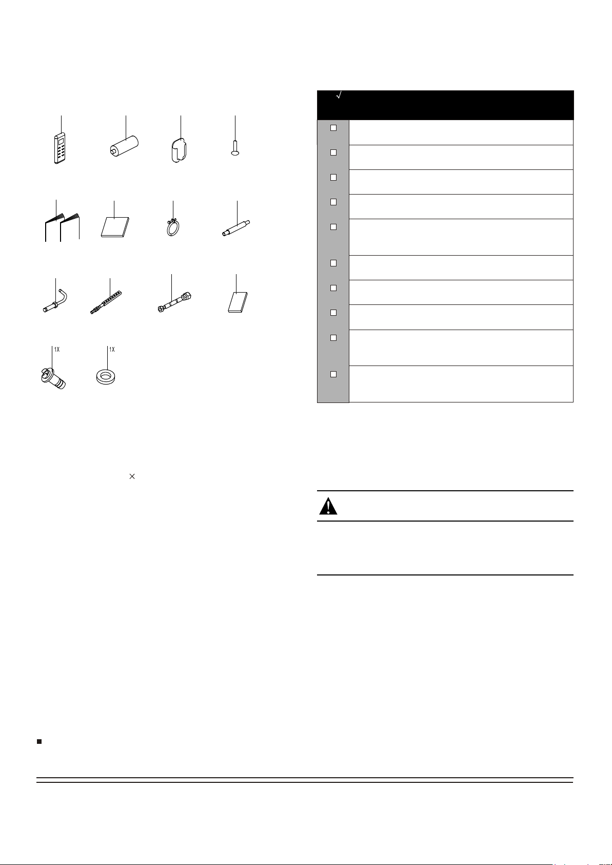
Check if the following accessories are included with your unit.
1
5
1X+1X
1X
2
2X
6
3
1X
7
1X1X
4
2X
8
1X
For the following items, take special care during
construction and check after installation is finished
Tick
when
checked
Is the indoor unit fixed firmly?
The unit may drop, vibrate or make noise.
Is the gas leak test finished?
It may result in insufficient cooling or heating.
Is the unit fully insulated?
Condensate water may drip.
Does drainage flow smoothly?
Condensate water may drip.
Does the power supply voltage correspond to that
shown on the name plate?
The unit may malfunction or components may burn out.
9 10
4X
11 12
1 Remote control
2 Batteries
3 Remote control holder (on some models)
4 Tapping screws (M3 10mm) (on some models)
5 Installation and owner's manual
6 Paper pattern for installation (on some models)
7 Metal champ (on some models)
8 Drain hose (on some models)
4X
11
1X 1X
12
Are wiring and piping correct?
The unit may malfunction or components may burn out.
Is the unit safely grounded?
Dangerous at electric leakage.
Is the wiring size according to specifications?
The unit may malfunction or components may burn out.
Is nothing blocking the air outlet or inlet of either the
indoor or outdoor units?
It may result in insufficient cooling or heating.
Are refrigerant piping length and additional refrigerant
charge noted down?
The refrigerant charge in the system might not be clear.
NOTE
All the pictures in this manual are for explanation purpose only.
There may be slightly different from the air conditioner you
purchased ( depend on model ). The actual shape may vary.
9 Expansible hooks (on some models)
10 Installation hooks (on some models)
11 Throttle (on some models)
12 Anti-shock rubber (on some models)
13 Drain plug (only heat pump models) (with the outdoor unit)
14 Seal ring (only heat pump models) (with the outdoor unit)
Optional accessories
This indoor unit requires installation of an optional decoration
panel.
3
Page 6
1. INDOOR UNIT INSTALLATION
For more info visit www.mrcool.com
1.1 Selecting installation site
When the conditions in the ceiling are exceeding 30C / 86 F and a
relative humidity of 80%, or when fresh air is inducted into the ceiling,
an additional insulation is required (minimum 0.4in / 10mm thickness,
polyethylene foam).
Select an installation site where the following conditions are
1)
fulfilled and that meets your customer's approval.
- Where optimum air distribution can be ensured.
- Where nothing blocks air passage.
- Where condensate water can be properly drained.
- Where the false ceiling is not noticeably on an incline.
- Where sufficient clearance for maintenance and service can be
ensured.
- Where there is no risk of flammable gas leaking.
- The equipment is not intended for use in a potentially explosive
atmosphere.
- Where piping between indoor and outdoor units is possible
within the allowable limit.(Refer to the installation manual of the
outdoor unit.)
- Keep indoor unit, outdoor unit, inter unit wiring and remote
control wiring at least 3.3 feet away from televisions and
radios.This is to prevent image interference and noise in those
electrical appliances.(Noise may be generated depending on
the conditions under which the electric wave is generated,even
if 3.3ft is kept.)
- When installing the wireless remote control kit, the distance
between wireless remote control and indoor unit might be
shorter if there are fluorescent lights who are electrically started
in the room.The indoor unit must be installed as far as possible
away from fluorescent lights.
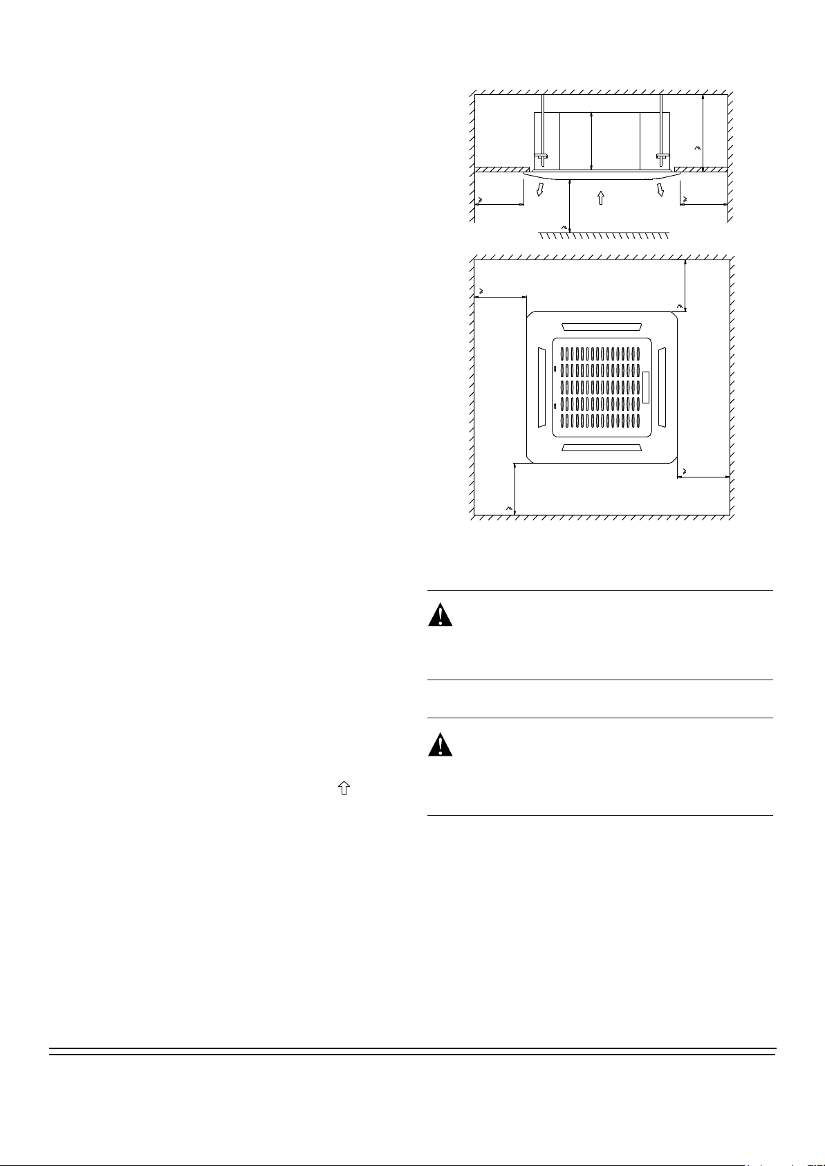
2)
Ceiling height
Install this unit where the height of bottom panel is more than
8.2ft / 2.5m so that the user cannot easily touch.
00
1000/39.4in
1000/39.4in
1000/39.4in
1 Air inlet
260/10.2in
2
2500/98.4in
1
2
290/11.4in
1000/39.4in
1000/39.4in
1000/39.4in
Unit: mm
2 Air outlet
DANGER
Do not install the unit in an area where flammable materials
are present due to risk of explosion resulting in serious
injury or death.
3)
Use installation hooks for installation. Check whether the
ceiling is strong enough to support the weight of the indoor
unit. If there is a risk, reinforce the ceiling before installing
the unit.
Space required for installation see the figure below ( :air flow
direction)
WARNING
If the basis underneath the unit is not strong enough to
support the weight of the unit, the unit could be fall out of
place and cause serious injury.
4
Page 7

1.2 Preparations before installation
For more info visit www.mrcool.com
Relation of ceiling opening to unit and suspension bolt
1)
position.
4
1
545/21.5in
570/22.4in
3
647/25.5in
5
523/20.6in
122
570/22.4in
647/25.5in
3
2) Make the ceiling opening needed for installation where
applicable.(For existing ceilings.)
- Create the ceiling opening required for installation. From the
side of the opening to the casing outlet, implement the
refrigerant and drain piping and wiring for remote control
(unnecessary for wireless type). Refer to each piping or wiring
section.
- After making an opening in the ceiling, it may be necessary to
reinforce ceiling beams to keep the ceiling level and to prevent
it from vibrating. Consult the builder for details.
3) Install the installation hooks. (Use either a M8 or M10
size bolt. )
Use expansible hooks, sunken anchors or other field supplied
parts to reinforce the ceiling in order to bear the weight of the
unit. Adjust clearance from the ceiling before proceeding further.
Installation example see figure below.
1
2
70/2.8in
15/0.6in
20/0.8in
1 Installation hook pitch dimensions
2 Indoor unit dimensions
3 decoration panel dimensions
4 Refrigerant piping
5 Installation hook ( 4)
6 Ceiling opening dimensions
7 Hanger bracket
8 False ceiling
Adjust the position to ensure the gaps between the indoor
unit and the four sides of false ceiling are even. The indoor
unit's lower part should sink into the false ceiling for
24mm / 0.9in.
1
20/0.8in
7
8
15/0.6in600/23.6in6
Unit: mm
1 Ceiling slab
2 Expansible hook (optional)
3 Installation hook (optional)
4 False ceiling
NOTE
For other installation than standard installation,
contact your dealer for details.
30~35mm
1.2~1.4in
3
4
2
0.9in
24mm
1 Indoor unit
2 False ceiling
NOTE:
Installation is possible with a ceiling dimension of 23.6in
/ 600 mm (marked with * ) . However, to achieve a
ceiling-panel overlapping dimension of 0.6in / 15 mm, the
spacing between the ceiling and the unit should be 0.8in
/ 20 mm or less. If the spacing between ceiling and the unit
is over 0.8in / 20 mm , attach sealing material in the part
or recover the ceiling.
5
Page 8

1.3 Install the indoor unit
For more info visit www.mrcool.com
When installing optional accessories, read also the installation
manual of the optional accessories. Depending on the field
conditions, it may be easier to install optional accessories before
the indoor unit is installed (except for the decoration panel).
However, for existing ceiling, install fresh air inlet component kit
and branch duct before installing the unit.
1) Install the indoor unit temporarily.
- Attach the hanger bracket to the suspension bolt. Be sure to
fix it securely by using a nut and washer from the upper and
lower sides of the hanger bracket.
- Securing the hanger bracket see figure below.
4) Check if the unit is horizontally levelled.
- Do not install the unit tilted. The indoor unit is equipped with a
built-in drain pump and float switch. (If the unit is tilted against
the direction of the condensate flow (the drain piping side is
raised), the float switch may malfunction and cause water to
drip.)
- Check if the unit is levelled at all four corners with a water level
or a water-filled vinyl tube as shown in figure below.
1
1
1
3
2
4
1 Nut (field supply)
2 Washer (field supply)
3 Hanger bracket
4 Double nuts (field supply,tighten)
2) Fix the paper pattern for installation. (For new ceilings only)
- The paper pattern for installation corresponds with the
measurements of the ceiling opening. Consult the builder for
details.
- The center of the ceiling opening is indicated on the paper
pattern for installation.
- After removing the packaging material from the paper patten for
installation, attach the paper pattern for installation to the unit
with the attached screws as shown in figure below.
2
1 Water level
2 Vinyl tube
5) Remove the paper pattern for installation. (For new ceiling
only).
2
1 Paper pattern for installation(on some models)
2 Center of the ceiling openiing
3 Screws(supplied with the decoration panel)
3) Adjust the unit to the right position for installation.
(Refer to the chapter "Preparations before installation" on page 5.)
1
2
3
6
Page 9

2. OUTDOOR UNIT INSTALLATION
For more info visit www.mrcool.com
2.1 Precautions for selecting the location
2.2 Figure of body size
1) Choose a place solid enough to bear the weight and vibration of
the unit, where the operation noise will not be amplified.
2) Choose a location where the hot air discharged from the unit or
the operation noise will not cause a nuisance to the neighbours
of the user.
3) Avoid places near a bedroom and the like, so that the operation
noise will cause no trouble.
4) There must be sufficient spaces for carrying the unit into and out
of the site.
5) There must be sufficient space for air passage and no
obstructions around the air inlet and the air outlet.
6) The site must be free from the possibility of flammable gas
leakage in a nearby place.
7) Install units, power cords and inter-unit wire at least 9.8ft away from
television and radio sets. This is to prevent interference to images
and sounds. (Noises may be heard even if they are more than 9.8ft
away depending on radio wave conditions.)
8) In coastal areas or other places with salty atmosphere of sulfate
gas, corrosion may shorten the life of the air conditioner.
9) Since drain flows out of the outdoor unit, do not place under the
unit anything which must be kept away from moisture.
Cannot be installed hanging from ceiling or stacked.NOTE:
F
MODEL A
780 548 266 300 241 250 540
9K~18K
(in=mm/25.4)
760 530 290 315 270 285 590
810
845
H
A
B
C
E
Unit:mm
B C D E F H
549
560
325
335
350
360
305
312
310
320
D
558
700
CAUTION
When operating the air conditioner in a low outdoor ambient
temperature, be sure to follow the instructions described below.
- To prevent exposure to wind, install the outdoor unit with its suction
side facing the wall.
- Never install the outdoor unit at a site where the suction side may
be exposed directly to wind.
- To prevent exposure to wind, it is recommended to install a baffle
plate on the air discharge side of the outdoor unit.
- In heavy snowfall areas, select an installation site where the snow
will not affect the unit.
- Construct a large canopy.
- Construct a pedestal.
Install the unit high enough off the
ground to prevent burying in snow.
7
Page 10

2.3 Installation guidelines
For more info visit www.mrcool.com
2.4 Outdoor unit installation
Where a wall or other obstacle is in the path of outdoor unit's
inlet or outlet airflow, follow the installation guidelines below.
For any of the below installation patterns, the wall height on the
outlet side should be 47.2in / 1200mm or less.
Wall facing one side
More than 100
Direction
of air
Side view
More than 350
1200
or less
Walls facing two sides
1) Installing outdoor unit
When installing the outdoor unit, refer to "Precautions for
selecting the location" .
Check the strength and level of the installation ground so that
the unit will not cause any operating vibration or noise after
installed.
Fix the unit securely by means of the foundation bolts.
(Prepare 4 sets of M8 or M10 foundation bolts, nuts and
washers each which are available on the market.)
Fix with bolts
More than 50
Walls facing three sides
More than 50
More
than 100
Top view
Top view
More
than 350
More than 100
More than 350
More than 50
Unit:mm
(in=mm/25.4)
2) Drain work
If drain work is necessary, follow the procedures below.
Use drain plug for drainage.
If the drain port is covered by a mounting base or floor surface,
place additional foot bases of at least 1.2in/30mm in height under
the outdoor unit's feet.
In cold areas, do not use a drain hose with the outdoor unit.
(Otherwise, drain water may freeze, impairing heating
performance.)
Drain port
Bottom frame
Seal
Drain plug
Hose
8
Page 11

3 INSTALL THE REFRIGERANT PIPE
For more info visit www.mrcool.com
3.1 Flaring the pipe end
All field piping must be provided by a licensed refrigeration
technician and must comply with the relevant local and
national codes.
Precautions
Execute heat insulation work completely on both sides of the
gas piping and liquid piping. Otherwise, this can sometimes
result in water leakage.
(When using a heat pump, the temperature of the gas piping can
reach up to approximately 120 /248 F. Use insulation which is
sufficiently resistant.)
Also, in cases where the temperature and humidity of the
refrigerant piping sections might exceed 30 /86 F or Rh80%,
reinforce the refrigerant insulation(20mm/0.8in or thicker).
Condensation may form on the surface of the insulating material.
Before rigging tubes, check which type of refrigerant is used.
Use a pipe cutter and flare suitable for used refrigerant.
Only use annealed material for flare conncetions.
Do not mix anything other than the specified refrigerant, such
as air, etc.., Inside the refrigerant circuit.
If the refrigerant gas leaks during the work, ventilate the area.
A toxic gas is emitted by the refrigerant gas being exposed to
a fire.
Make sure there is no refrigerant gas leak. A toxic gas may be
released by the refrigerant gas leaking indoor and being
exposed to flames from an area heater, cooking stove, etc.
Refer to the table below for the dimensions of flare nuts spaces
and the appropriate tightening torque. (Overtightening may
damage the flare and cause leaks.)
Pipe gauge
(mm)
O6.35(1/4 in)
O9.52(3/8in)
O12.7(1/2in)
O15.9(5/8in)
Tightening torque
15~16 N. m
(153~163 kgf.cm)
25~26 N. m
(255~265 kgf.cm)
35~36 N. m
(357~367 kgf.cm)
45~47 N. m
(459~480 kgf.cm)
Flare dimension
A (mm)
8.3~8.7
0.327~0.343in
12.0~12.4
0.472~0.488in
15.4~15.8
0.606~0.622in
18.6~19.0
0.732~0.748in
O
O
Flare shape
o
90
4
45
A
o
2
R0.4~0.8
0.016~0.031in
1) Cut the pipe end with a pipe cutter.
2) Remove burrs with the cut surface facing downward so that the
chips do not enter the pipe.
Cut exactly at
right angles.
Remove burrs.
3) Put the flare nut on the pipe.
4) Flare the pipe.
(in=mm/25.4)
Max.
1.3
1.6
1.8
2.2
A(mm)
Min.
0.7
1.0
1.0
2.0
Set exactly at the position shown below.
A
Copper pipe
Outer diam.
(mm)
O6.35(1/4 in)
O9.52(3/8in)
O12.7(1/2in)
O15.9(5/8in)
5) Check that the flaring is properly made.
The pipe end must
be evenly flared in a
Flare's inner surface
perfect circle.
must be flaw-free
Make sure that the
flare nut is fitted.
3.2 Refrigerant piping
Coat the flare both inside and ouside with ether oil or ester oil .
Coat here with ether oil or ester oil
Die
Check whether the height drop between the indoor unit and
outdoor unit, and the length of refrigerant pipe meet the following
requirements:
The type of models
T1 condition
Split type air conditioner
R410A inverter
Split type air conditioner
T3 condition
(outdoor unit down)
T3 condition
(outdoor unit up)
Capacity
(Btu/h)
9K ~12K
18K
9K ~12K
18K
9K ~12K
18K
9K ~12K
18K
Max.allowable
piping length
15m/49.2ft
25m/82ft
25m/82ft
30m/98.4ft
25m/82ft
30m/98.4ft
25m/82ft
30m/98.4ft
Max.allowable
piping height
8m/26.2ft
15m/49.2ft
10m/32.8ft
20m/65.6ft
10m/32.8ft
15m/49.2ft
15m/49.2ft
20m/65.6ft
Align the centres of both flares and tighten the flare nuts 3 or 4
turns by hand. Then tighten them fully with the torque wrenches.
1 Torque wrench
2 Flare nut
3 Piping union
4 Spanner
1 2
4
3
9
Page 12

3.3 Installation of the throttle. (For some models)
For more info visit www.mrcool.com
500mm/19.7in
3.4 Purging air and checking gas leakage
When piping work is completed, it is necessary to purge the
air and check for gas leakage.
WARNING
1
2
3
1 Throttle
2 Liquid pipe
3 Gas pipe
Precautions
- For ensuring throttled efficiency, please mount the throttle
as horizontally as possible.
Indoor
Outdoor
Do not mix any substance other than the specified refrigerant
into the refrigeration cycle.
When refrigerant gas leaks occur, ventilate the room as soon as
possible.
The specified refrigerant should always be recovered and never
be released directly into the environment.
Use a vacuum pump for the specified refrigerant. Using the
same vacuum pump for different refrigerants may damage the
vacuum pump or the unit.
If using additional refrigerant, perform air purging from the
refrigerant pipes and indoor unit using a vacuum pump, than
charge additional refrigerant.
Use a hexagonal wrench(0.2in / 4mm) to operate the stop valve
rod.
All refrigerant pipe joints should be tightened with a torque
wrench at the specified tightening torque.
Outdoor
Indoor
Indoor
Outdoor
- Wrap the supplied anti-shock rubber at external of the
throttle for denoise.
1) Connect projection side of charging hose (which comes from
gauge manifold) to gas stop valve's service port.
2) Full open gauge manifold's low-pressure valve (Lo) and
completely close its high-pressure valve (Hi)
(High-pressure valve subsequently requires no operation.)
3) Do vacuum pumping and make sure that the compound
pressure gauge reads -0.1MPa (-76cmHg).*1
4) Close gauge manifold's low-pressure valve (Lo) and sop
vacuum pump.
(Keep this state for a few minutes to make sure that the
compound pressure gauge pointer does not swing back.)*2
5) Remove caps from liquid stop valve and gas stop valve.
6) Turn the liquid stop valve's rod 90 degrees counterclockwise
with a hexagonal wrench to open valve.
Close it after 5 seconds, and check for gas leakage.
Using soapy water, check for gas leakage from indoor unit's
flare and outdoor unit's flare and valve rods.
After the check is complete, wipe all soapy water off.
7) Disconnect charging hose from gas stop valve's service port
then fully open liquid and gas stop valves.
(Do not attempt to turn valve rod byond its stop.)
8) Tighten valve caps and service port caps for the liquid and
gas stop valves with a torque wrench at the specified torques.
1 Anti-shock rubber
2 Throttle
*1. Pipe length vs. Vacuum pump run time
10
Page 13

Pipe length Up to 49.2ft / 15m More than 49.2ft / 15m
For more info visit www.mrcool.com
Not less than 15minNot less than 10 minRun time
*2. If the compound pressure gauge pointer swings back,
refrigerant may have water content or a loose pipe joint may
exists. Check all pipe joints and retighten nuts as needed,
then repeat steps 2) through 4).
3.5 Additional refrigerant charge
CAUTION
Refrigerant may only be charged after performing the leak
test and the vacuum pumping.
Check the type of refrigerant to be used on the machine
nameplate. Charging with an unsuitable refrigerant may
cause explosions and accidents, so always ensure that the
appropriate refrigerant is charged.
Refrigerant containers shall be opened slowly.
The outdoor unit is factory charged with refrigerant. Calculate the
added refrigerant according to the diameter and the length of the
liquid pipe of the outdoor unit/indoor unit connection.
Pipe length and refrigerant amount:
Connective
pipe length
Less
than 24.6ft
More
than 24.6ft
Air purging
method
Use vacuum
pump.
Use vacuum
pump.
Additional amount of refrigerant to be charged
Liquid side: 1/4in / 6.35mm
R410A: (Pipe length-7.5(25))x15g/m(0.16oz/ft)
Liquid side: 3/8in / 9.52mm
R410A: (Pipe length-7.5(25))x30g/m(0.32oz/ft)
2) Be sure to insulate both the gas and liquid piping. Use
separate thermal insulation pipes for gas and liquid
refrigerant pipes. See the figure below.
Inter-unit wire
Gas pipe
Gas pipe
insulation
Finishing tape
3) Finally, insulate as shown in the figure below.
1 Liquid pipe
2 Gas pipe
6
5
3
1
2
4
3 Insulation for liquid pipe fitting
4 Insulation for gas pipe fitting
5 Clamps
(use 2 clamps per insulation)
6 Indoor unit
Liquid pipe
Liquid pipe
insulation
Drain hose
Piping insulation procedure
Gas piping Liquid piping
116
3
2
66445
3
6
2
5
Be sure to add the proper amount of additional refrigerant.
Failure to do so may result in reduced performance.
3.6 Refrigerant pipig work
1) Caution on the pipe handling
Protect the open end of the pipe against dust and moisture.
All pipe bends should be as gentle as possible. Use a pipe
bender for bending.
Rain
Be sure to
place a cap.
If no flare cap is
available, cover the
flare mouth with
tape to keep dirt or
water out.
Wall
A
1 Piping insulation material(field supply)
2 Flare nut connection
3 Insulation for fitting (field supply)
4 Piping insulation material (main unit)
5 Indoor unit
6 Clamp (field supply)
A Turn seams up
B Attach to base
C Tighten the part other than the piping insulation material
C
For local insulation, be sure to insulate local piping
all the way into the pipe connections inside the unit.
Exposed piping may cause condensation or may
cause burns when touched.
Make sure that no oil remains on plastic parts of the
decoration panel (optional equipment).
Oil may cause degradation and damage to plastic
parts.
B
A
C
B
11
Page 14

4 CONNECT THE DRAIN PIPE
For more info visit www.mrcool.com
4.3 How to perform piping
4.1 Installation of drain piping
Install the drain piping as shown in figure below and take measures
against condensation. Improperly rigged piping could lead to leaks
and eventually wet furniture and belongings.
1-1.5m
3~5ft
1
2
1 Hanging bar
2 1/100 gradient
4.2 Install the drain pipes.
- Keep piping as short as possible and slope it downwards at a
gradient of at least 1/100 so that air may not remain trapped
inside the pipe.
- Keep pipe size equal to or greater than that of the connecting
pipe (PVC pipe, nominal diameter 0.8in / 20mm in, outside
diameter 1in / 25mm).
- Push the drain hose as far as possible over the drain socket,
and tighten the metal clamp securely.
300/11.8in
5
0~75
0~3in
6
1 Ceiling slab
2 Hanger bracket
3 Adjustable range
4 Drain raising pipe
5 Drain hose
6 Metal clamp
- Connect the drain hose to the drain raising pipes, and
insulate them.
- Connect the drain hose to the drain outlet on the indoor unit,
and tighten it with the clamp.
Precautions
- Install the drain raising pipes at a height of less than 20.9in
/ 530mm.
- Install the drain raising pipes at a right angle to the indoor
unit and no more than 11.8in / 300mm from the unit.
- To prevent air bubbles, install the drain hose level or slightly
tilted up (<3in / 75mm).
- The incline of drain hose should be 3 in / 75 mm or less so
that the drain socket does not have to withstand additional force.
- To ensure a downward slope of 1:100, install hanging
bars every 3.3ft / 1m to 4.9ft / 1.5m.
- When unifying multiple drain pipes, install the pipes as
shown in figure below. Select converging drain pipes whose
gauge is suitable for the operating capacity of the unit.
1~1.5m
3~5ft
3
4
5
Unit: mm
1
2
530/20.9in
750/29.5in
220/8.7in
1 2
1 Drain socket (attached to the unit)
2 metal clamp
3 Drain hose
4 Insulation (field supply)
- Insulate the drain hose inside the building.
- If the drain hose cannot be sufficiently set on a slope, fit the
hose with drain raising piping (field supply).
- Make sure that heat insulation work is executed on the
following 2 spots to prevent any possible water leakage due
to dew condensation.
1 Indoor drain pipe.
2 Drain socket.
3 4
12
0-530
100
1 T-joint converging drain pipes
Drain piping connections
Do not connect the drain piping directly to sewage
pipes that smell of ammonia. The ammonia in the
sewage might enter the indoor unit through the drain
pipes and corrode the heat exchanger.
Keep in mind that it will become the cause of getting
drain pipe blocked if water collects on drain pipe.
1
1
Unit: mm
Page 15

4.4 Testing of drain piping
For more info visit www.mrcool.com
After the piping work is finished, check if drainage flows smoothy.
Add approximately 1L of water gradually through the air discharge
outlet.
Method of adding water (see the figure below)
106/4.2in
75/3in
65/2.6in
100/3.9in
1 2
1 Plastic watering can(tube should be about 3.9in/100 mm long)
2 Water-receiver
When exlectric wiring work is finished, check drainage flow during
COOL running, exlplained in "Test operation" on page 16.
Fresh air intake ( 65/2.6in)
Unit: mm
106/4.2in
5 ELECTRIC WIRING WORK
General instructions
All field wiring and components must be installed by a licensed
electrician and must comply with relevant European and national
regulations.
Use copper wire only.
Follow the 'Wiring diagram' attached to the unit body to wire the
outdoor unit, indoor units and the remote controller.
A circuit breaker capable of shutting down power supply to the
entire system must be installed.
Note that the operation will restart automatically if the main
power supply is turned off and then turned back on again.
Be sure to ground the air conditioner.
Do not connect the ground wire to gas pipes, water pipes,
lightning rods, or telephone ground wires.
- Gas pipes: might cause explosions or fire if gas leaks.
- Water pipes: no grounding effect if hard vinyl piping is used.
- Telephone ground wires or lightning rods: might cause
abnormally highelectric potential in the ground during
lightning storms .
The specification of power
Power
Model
9K~18K
Phase
1Phase 208-240V
Frequency and volt
Circuit breaker/Fuse(A)
20/16
13
Page 16

How to connect wiring
For more info visit www.mrcool.com
Remove the control box lid of the indoor unit.
Remove the cover of the outdoor unit.
Follow the "Wiring diagram label" attached to the indoor unit's control box lid to wire the outdoor unit, indoor unit and the remote control.
Securely fix the wires with a field supplied champ.
Attach the cover of the outdoor unit.
1
3
1 Control box lid
4
5
6
7
Precautions
Observe the notes mentioned below when wiring to the power
1
supply terminal board.
- Do not connect wires of different gauge to the same power
supply terminal. (Looseness in the connection may cause
overheating.)
- When connecting wires of the same gauge, connect them
according to the figure.
2 Wiring diagram label
3 Power supply terminal block
4 Clamp for wiring
5 Wiring between units
6 Plastic cover
7 Clamp (field supply)
2
Cover
Bolts
Use the specified electric wire. Connect the wire securely to
the terminal. Lock the wire down without applying excessive
force to the terminal. (Tightening torque: 1.31N.m 10%).
- When attaching the control box lid, make sure not to pinch
any wires.
- After all wiring connections are done, fill in any gaps in the
casing wiring holes with putty or insulation material (field
supply) thus to prevent small animals or dirt from entering
the unit from outside and causing short circuits in the control
box.
Do not connect wires of different gauge to the same grounding
2
terminal. Looseness in the connection may deteriorate the
protection.
Use only specified wires and tightly connect wires to the terminals.
3
Be careful that wires do not place external stress on the terminals.
Keep wiring in neat order so that they do not obstruct other
equipment such as popping open the service cover. Make sure
the cover closes tight. Incomplete connections could result in
overheating, and in the worst case, electric shock or fire.
14
Page 17

6 INSTALLATION OF THE DECORATION PANEL
For more info visit www.mrcool.com
Detach the intake grille.
- Slide the 2 grille hooks toward the middle of the decoration
panel.
1
2
- After installing the decoration panel, ensure that there is no
space between the unit body and decoration panel.
Otherwise air may leak through the gap and cause dewdrop.
(See figure below)
1 Intake grille
2 Grille hook
- Open the intake grille and remove.
- Align the indicate " " on the decoration panel to the indicate
" " on the unit .
- Attach the decoration panel to the unit with the supplied screws
as shown in figure below.
Install the decoration panel
Mount the intake grille.
Ensure that the buckles at the back of the grille be properly
seated in the groove of the panel.
Connect the 2 wires of the decoration panel to the
mainboard of the unit.
1 Decoration panel
2 Screws (M5)(supplied with the panel)
5-core wire
1
Fasten the control box lid with 2 screws .
2
10-core wire
15
Page 18

Close the intake grille, and close the 2 grille hooks.
For more info visit www.mrcool.com
7 TEST OPERATION
Make sure the control box lids are closed on the indoor and outdoor
units.
Refer to ''For the following items, take special care during construction
and check after installation is finished'' on page 2.
After finishing the construction of refrigerant piping, drain piping, and
electric wiring, conduct test operation accordingly to protect the unit.
Test operation after installing decoration panel
Open the gas side stop valve.
1
Open the liquid side stop valve.
2
Electrify crank case heater for 6 hours.
3
Set to cooling operation with the remote control and start
4
operation by pushing ON/OFF button.
5
Check the following points. If there is any malfunction, please
resolve it according to the chapter "Troubleshooting" in the
"Owner's Manual".
The indoor unit
- Whether the switch on the remote control works well.
- Whether the buttons on the remote control works well.
- Whether the air flow louver moves normally.
- Whether the room temperature is adjusted well.
- Whether the indicator lights normally.
- Whether the temporary buttons works well.
- Whether there is vibration or abnormal noise during operation.
- Whether the drainage flows smoothly.
The outdoor unit
- Whether there is vibration or abnormal noise during operation.
- Whether the generated wind, noise, or condensed of by the air
conditioner have influenced your neighborhood.
- Whether any of the refrigerant is leaked.
Turn off the main power supply after operation.
6
A protection feature prevents the air conditioner from being
activated for approximately 3 minutes when it is restarted
immediately after shut off.
16
Page 19

Olympus Series
For more info visit www.mrcool.com
Cassette Air Handlers
The design and specifications are subject to change without prior notice.
Consult with the sales agency or manufacturer for details.
 Loading...