

Page 1
DATALOGGING AC/DC CLAMP POWER METER
TES - 3060/3063
INSTRUCTION MANUAL
PLEASE READ THIS MANUAL CAREFULLY BEFORE OPERATION
3, Hagavish st. Israel 58817 Tel: 972 3 5595252, Fax: 972 3 5594529 mrc@mrclab.com
MRC.7.14
Page 2

CONTENTS
I. SAFETY INFORMATION
.........................................................1
II. TECHNICAL SPECIFICATIONS
...............................................3
2-1 Environment Conditions
...................................................3
2-2 Maintenance .....................................................................3
2-3 Features............................................................................3
2-4 General Specifications......................................................4
2-5 Measurement Specifications ............................................5
III. PARTS & CONTROLS
.............................................................7
3
-1 Description of Parts & Control .......................................... 7
IV. AC+DC POWER MEASUREMENT
........................................11
4-
1 AC+DC 1φ2W Power(W) and Power Factor (PF)
Measurement ..................................................................11
4-2 3φ3W AC+DC Power Measurement...............................13
4-3 3φ4W AC+DC Power Measurement...............................17
4-4 1φ3W Power Measurement ............................................20
V. OPERATING INSTRUCTION...............................................24
5-1 AC+DC Voltage Measuremen ........................................24
5-2 AC+DC Current Measurement .......................................25
5-3 To Improve Power Factor of a 3φ4W Power System ...26
5-4 To Improve Power Factor of a 3φ3W Power System ....26
5-5 To Improve Power Factor of a 1φ2W Power System ....27
5-6 Resistance & Continuity Measurement ..........................27
5-7 Diode Test & Continuity Measurement...........................28
5-8 Peak Detection Measurement ........................................28
5-9 Operation Of Data Record And Read.............................29
VI. BATTERY REPLACEMENT ................................................
30
Page 3
1
I.
SAFETY INFORMATION
Read the following safety information carefully before
attempting to operate or service the meter.
To avoid damages to the instrument do not exceed the maximum
limits of the input values shown in the technical specification
tables.
Do not use the meter or test leads if they look damaged. Use
extreme caution when working around bare conductors or bus
bars.
Accidental contact with the conductor could result in electric shock.
Use the meter only as specified in this manual; otherwise, the
protection provided by the meter may be impaired.
Read the operating instructions before use and follow all safety
information.
Caution when working with voltages above 60VDC or 30VAC
RMS. Such voltages pose a shock hazard.
Before taking resistance measurements or testing acoustic
continuity, disconnect circuit from main power supply and all
loads from circuit.
Safety symbols
Caution refer to this manual before using the meter.
Dangerous volt
ages.
Meter is protected throughout by double insulation or
reinforced insulation.
When servicing, use only specified replacement
parts.
Comply with EN-61010-1, IEC 1010-2-32
Page 4

3
II.
TECHNICAL SPECIFICATIONS
2-1 Environment Conditions:
Installation categories III
Pollution degree 2
Altitude up to 2000 meters
Indoor use only
Relatively humidity 80% max.
Operation ambient 0 〜50℃
2-2 Maintenance
Repairs or servicing not covered in this manual should
only be performed by qualified personnel.
Periodically wipe the case with a dry cloth. Do not use
abrasives or solvents on this instruments.
2-3 Features•
RS-232 interface to talk with PC
4000 continuity point data logger , 25 point manual
data logger
True Power / Apparent Power / Power Factor
measurement
True RMS. V, A, W, lead, Iag, PF indicator
4 digits with dual display LCD
MIN / MAX Measurement
Amp / Voltage frequency measurement
PEAK HOLD detector
Dual display KW + PF , KVA + PF , V+A
Dual display A + Hz , V + Hz
Page 5

4
2-4 General Specifications
Maximum voltage between any terminal and earth ground
:
600Vrms.
Numerical dual display :4 digit liquid crystal display
(LCD) maximum reading 9999.
Bargraph display
:
40 segments.
Battery life
:
30hr approx. (Alkaline).
Low battery indication
:
The
is displayed when the
battery voltage drops below the
operating voltage.
Auto power off time
:
30 minutes approx.
Sampling rate
:
5 times / sec ( Barograph ),
5 times / sec ( Digital display )
1 times /3sec ( on kw function )
Jaw opening diameter :Cables φ 46mm.
Operating temperature
:0℃
to 50℃ (32℉ to 122℉)
and humidity R.H. < 80% non-condensing.
Storage temperature
:
-10℃to 60℃ (14℉to 140℉)
and humidity R.H. < 70% non-condensing.
Dimensions
:
260(L) x 93(W) x 45mm(H).
Weight
:
Approx. 450 g.
Accessories
:
Carrying case, Test leads,
Battery (one 006p 9V) &
Instruction manual.
Optional Accessory : RS-232 interface & computer
P.C. software.
Page 6

5
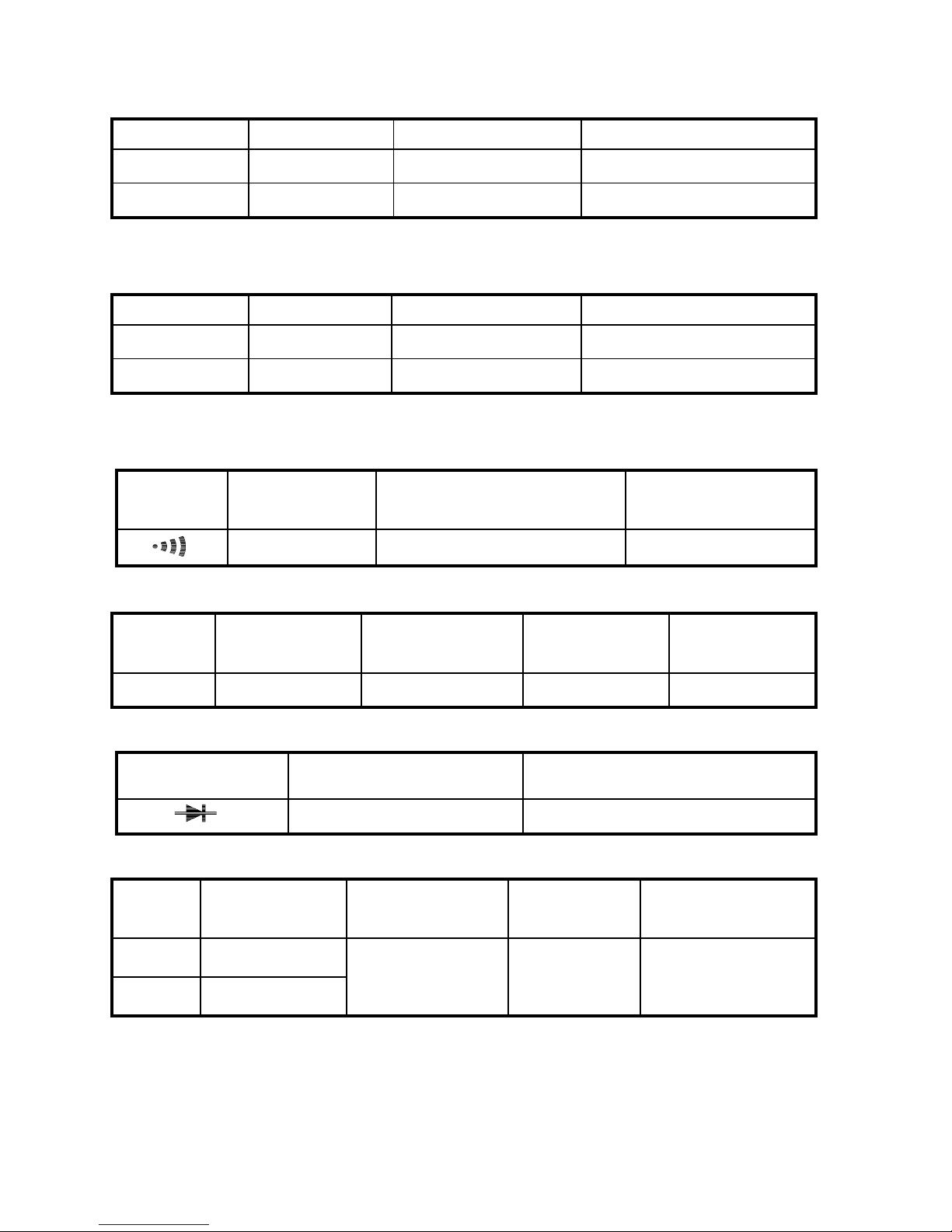
2-5 Measurement Specifications
Accuracy are•±(• of reading • number of digits) at 18• to
28• ( 64• to 82•) with relative humidity to 80•.
TRUE power & Apparent power measurement
Input Resolution Accuracy
Frequency
range
Overload
protection
V<130V , A<150A
V>130V , A<150A
V<130V , A>150A
0.01
±
(2%+5)
V>130V , A>150A 0.1
±
(2%+1)
45Hz〜
500Hz
600V/1100A
DCA
Range Resolution Accuracy Overload protection
1000A 0.1A
±
( 1.5% + 5)
1100A
ACA
Range Resolution Accuracy
Frequency
range
Overload
protection
1000A 0.1A
±
( 1.5% + 5)
45Hz〜500Hz
1100A
※
Crest factor : < 3 for stated accuracy
DCV
Range Resolution Accuracy
Input
impedance
Overload
protection
600V 0.1V
±
(0.5% + 5)
1MΩ
600V
ACV
Range Resolution Accuracy
Input
impedance
Frequency
range
Overload
protection
600V 0.1V
±
( 0.5%+5)
1MΩ
45Hz
〜
500Hz
600Vrms
※
Crest factor : < 3 for stated accuracy
Page 7
6
Peak indication
Range Resolution Accuracy Overload protection
20A~80A 0.1A
±
(10% + 10)
1100A
80A~1000A 0.1A
±
( 6% + 10)
1100A
※
Peak detect acquisitions time ≦1ms
Peak indication
Range Resolution Accuracy Overload protection
20V~80V 0.1V
±
(10% + 10)
600Vrms
80V~600V 0.1V
±
( 6% + 10)
600Vrms
※
Peak detect acquisitions time ≦1ms
Audible continuity
Range
Continuity
beeper
Open circuit voltage
Overload
protection
< 0.050
≦
3.2V
600Vrms
Resistance ( Ω )
Range Resolution Accuracy
Open circuit
voltage
Overload
protection
10KΩ 1Ω
±
( 1 ﹪ + 5)
≦
3.2 V
600Vrms
Diode test
Range Resolution Overload protection
0.001V 600Vrms
Frequency ( Hz )
Range Resolution Accuracy
Voltage
sensitivity
Overload
protection
1KHz 0.1Hz
5KHz 1Hz
±
(0.5% + 5)
10V or 10A 600V / 1100A
Optional accessories:
RS-232 interface adaptor / software
Page 8

7
III.
PARTS & CONTROLS
3-1 Description of Parts & Control
KW
K
KVA
P P-
3 3W
ME M
PF lead lag
WL123 READ
3 4W Hz
KVA
MINMA X HOLD -
REC ORD
HOLD
Hz
1000A
OFF
V
3 4W
3 3W
KW
600V CATMAX
(Figure-1)
Press and hold the button until the beeper
sounds that means the function activating.
Page 9

8
(1). Transformer jaws
Pick up the AC and DC current flowing through the conductor.
(2). Jaw opening trigger.
(3). Data Hold button
Press it once to hold the measured value and store the
value in memory. Press again to release hold function.
(4). Function selector
For selection of desired function, and awakening from autopower-off mode.
(5). Yellow button (P+ or P- selection)
a. Press “Yellow” button once, LCD will display “P+P
-”
symbo
l, then press “PEAK” button to measure peak
value of a transient signal.
b. Press “Yellow” button until the RE
AD symbol is shown on
LCD and then P
ress “
•
” button to read the previous data.
Press “
•
” button to read the next data. Press “Yellow”
button again to exit.
c. When the rotary switch is set to KW function, press this
button to select KW/PF, A/V or KVA/PF dual displayed.
d. When the rotary switch is set to the 3
•
3W or 3•4W
func
tion, press on the yellow button to select the phase
to be measured.
(6). MIN/MAX/PEAK function button
a. Press it once to select MIN or MAX. Keep pressing it
for
2 seconds to exit MIN/MAX mode.
b.
Press “Yellow” button once
then press this button to
measure peak value P+ or P
- of a transient signal, keep
pressing it for 2 seconds to exit peak mode. It can be
used in ACV and ACA. One of the most common
applications is the measurement of the current value
when starting electrical motors. When measuring
alternating signals, LCD shows the peak value.
(7). DC A/W ZERO button
Page 10

9
Press the button once to zero the A or KW reading.
(8). RECORD button
•
Single Data Record
The clamp meter can store 25 data record in memory.
Once the button is pressed, the data number and
RECORD symbol will be shown on LCD. If the memory is
full, the FULL signal will be shown on LCD when the
record button is pressed.
•
Continue Data Record
The memory size is of 4000 records. To start recording
data, press the RE
CORD button until 2 “beep” sounds
heard and “RECORD” symbol will be shown on LCD. To
stop recording data, press the RECORD button again until
the RECORD symbol disappears.
•
Clear data logger
To clear the memory of the meter, turn the instrument off.
Press on the RECORD button and power on the
instrument. The LCD will show CLr.
(9). LCD display
4 digital LCD with indications for measurement values, unit
symbols, decimal point, polarity, over range, and low
battery ; etc.
(10). RS-232 PC Interface Jack
To connect the RS-232 interface to the PC and meter.
(11). COM Jack
Connect black test lead for voltage, frequency, resistance,
continuity and diode measurement as a negative terminal.
(12). " V
•
Hz " Jack
Connect red test lead for voltage, frequency, resistance,
continuity and diode measurement as a positive terminal.
Page 11

10
KW
K
KVA
P P-
3 3W
ME M
PF lead lag
WL123 READ
3 4W Hz
KVA
MINMA X HOLD -
REC ORD
READ
3 4W
PF lead lag
WL123
REC ORD
3 3W
ME M
KVA
KW
Hz
KVA
K
MA X
P P-HOLD MIN-
(Figure-2)
(13). Low Battery:
A
s battery power is not sufficient .
Will be displayed
as a symbol of low battery.
(14). Analog Display Scale.
(15). Analog Display.
(16). Units Symbols.
Page 12

11
IV.
AC+DC POWER MEASUREMENT
WARNING
Wait until “- - - -” symbol is shown on LCD before clamping
on to any conductor and pressing on the ZERO button to
zero any residual magnetic field in the jaws.
4-1 AC+DC 1φ2W Power(W) and Power Factor (PF) Measurement
KW
PF lag
HOLD
Hz
1000A
OFF
V
3 4W
3 3W
KW
600V CATMAX
600V MAX CAT
PF lag
KW
(Figure-3)
Turn the clamp on with the jaws clamped on to no conductor.
Set the rotary switch to KW (refer to figure 3).
Insert the test leads into the input terminals.
Page 13

12
Connect the test probe of COM (black) terminal to the
neutral line.
Connect the test probe of V (red) terminal to the power line.
Clamp the conductor where V (red) terminal is connected.
The power clamp will automatically select the appropriate range.
Read the Watt and PF values displayed on the LCD.
Press YELLOW button to select KW/PF, A/V, or KVA/PF.
KVAR is a calculated value, and its accuracy greatly
depends on the accuracy of V, A and KW especially when
PF is very close to 1. To get a more accurate value when
PF is greater than 0.91 (φ < 25°), users can obtain KVAR by
themselves from the following equation for pure sine wave
input :
PF
KW
KVA
=
KVA (Apparent Power) :
KVA =
VA*
1000
KVAR (Reactive Power) : KVAR=
(KVA) (KW)
22
−
NOTE
The "+" sign printed on jaw must face the power source for
accurate measurement.
Page 14

13
4-2 3φ3W AC+DC Power Measurement
KW
600V MAX CAT
WL12
3 3W
3 3W
PF lag
WL12
KW
MAX600V CAT
WL12
PF lag
3 3W
3 4W
KW
3 3W
V
1000A
Hz
HOLD
OFF
(Figure-4)
Page 15

14
600V CATMAX
WL 23
PF lag
3 3W
KW
MAX CAT600V
WL 23
PF lag
3 3W
KW
3 4W
V
KW
3 3W
1000A
Hz
OFF
HOLD
WL 23
3 3W
(Figure-5)
600V
PF la g
3 3W
WL123
KW
MAX CAT
HOLD
(Figure-6)
Page 16

15
First, measure W
RS(L1L2)
(refer to figure 4).
a. Turn the power on without clamping to any wire.
b. Set the rot
ary switch at 3φ3W, and W
L12
symbol will
appear to instruct users to take measurement of W
RS(L2L1)
.
c. Insert the test leads into the input ja
ck.
d.
Select one phase (eg. S or L2) as COM and connect
the
test probe of the COM (black) terminal to that phase (eg.
S or L2).
e. Connect the t
est probe of V (red) terminal to
the second
phase (eg. R or L1).
f. Clam
p the same phase as
step e. (eg. R or L1).
g. The power clamp will automatically select proper range.
h.
Wait until the reading is
stable (about 3~6 seconds),
press the YELLOW button and W
L23
symbol will appear
to instruct users to take measurement of W
TS
(W
L3L2
).
Second, measure W
TS(L3L2)
(refer to figure 5).
a. Disconnect the test probe from the phase where jaws
is
clamp on in previous m
easurement.
b. Connect the test probe to t
he third phase (eg. T or L3).
c.
Camp the third phase where te
st probe is connected to
(eg. T or L3)
d. The power clamp will automat
ically select proper range.
e. Wait
until the reading is stable (about 3~6 seconds),
press the YELLOW button.
Page 17

16
The power clamp will process those two sets of data (W
L12
,
W
L23
), and show the result on the LCD. W
L123
symbol will
be shown to indicate the watt of 3φ3W power.
At this moment, the watt of 3φ3W power is stored into the
memory.
If willing to read the details of that singly data record,
please refer to 5-9.
W
3φ3W
= W
RS(L1L2)
+ W
TS(L3L2)
KVA K
W
KVAR
WW W33
2
33
2
33
φφ φ
=+
PF
KW
KVA
W
W
W
33
33
33
φ
φ
φ
=
If willing to record data (W
L12
or W
L23
), press “RECORD”
button to complete.
NOTE
Once a phase is selected as COM, users can not change this
selection in the subsequent measurement. For example, if S (or
L2) phase is selected, S (or L2) phase is always connected to the
COM during measurement of W
RS
(or W
L1L2
) and W
TS
(or W
L3L2
)
in 3φ 3W unbalanced power.
NOTE
The "+" sign print
ed on jaw must face the power source, and
make sure all the connections and clamping are correct for correct
measurement.
NOTE
In the 3φ3W unbalanced power measurement
, one of W
RS
or
W
TS
could be negative. Users must make sure all the
connections and clamping are correct to obtain correct power.
Page 18

17
4-3 3φ4W AC+DC Power Measurement
KW
600V MAX CAT
PF lag
WL1
3 4W
MAX600V CAT
WL1
3 4W
PF lag
KW
3 4W
3 3W
V
1000A
KW
Hz
HOLD
OFF
WL1
3 4W
(Figure-7)
HOLD
CAT600V MAX
WL 2
PF lag
KW
3 4W
600V CATMAX
PF lag
WL 2
3 4W
KW
KW
3 3W
3 4W
1000A
OFF
Hz
V
WL 2
3 4W
(Figure-8)
Page 19

18
600V CATMAX
PF lag
KW
WL 3
3 4W
MAX600V CAT
3 4W
WL 3
3 4W
PF lag
KW
OFF
Hz
V
KW
3 3W
1000A
HOLD
W L 3
3 4W
(Figure-9)
600V
PF lag
WL123
KW
MAX CAT
HOLD
3 4W
(Figure-10)
Page 20

19
a. Turn the power on without clamping on to any wire.
b. Set
the rotary switch at 3
φ
4W
.
c.
Insert the test leads into the input ja
ck.
d. Connect the neutral line to the COM (black) terminal.
e. Connect the test probe
of the V (red) terminal to the first
phase (eg. R or L1).
f. Clamp on to the same phase (eg.
R or L1).
g.
The power clamp meter will
automatically select proper
range.
h. Wait unt
il the reading is
stable (about 3~6 seconds),
press the YELLOW button,
and W
L1
symbol will disappear.
and W
L2
symbol appears to instruct users to take
measurement of W
S(L2)
/PF
S(L2)
.
Second, measure W
S(L2)
/PF
S(L2)
(refer to figure 8)
a. Disconnect the test probe from the phase where jaws
is
clamp on in previous measurem
ent.
b. Connect the test probe of t
he V (red) terminal to the
second phase (eg. S or L2).
c.
Clamp the phase where test probe is connected to
(eg. S
or L2 phase)
d. The power clamp will automat
ically select proper range.
e. Wait
until the reading is stable (about
3~6 seconds),
press t
he YELLOW button, and W
L2
symbol will disappear.
W
L3
symbol will appear to instruct users to take
measurement of W
T(L3)
/PF
T(L3)
.
Third, measure W
T(L3)
/PF
T(L3)
(refer to figure 9)
a. Disconnect the test probe from the phase where ja
ws
clamped in previous measurem
ent.
b. Connect the test probe of the V (red) terminal to th
e third
phase (eg. T or L3 phase).
c.
Clamp the phase where test
probe is connected to (eg.
T or L3).
First, measure W
R(L1)
/PF
R(L1)
(refer to figure 7).
Page 21

20
d. The power clamp will automatically select proper range.
e. Wait unt
il the reading is st
able (about 3~6 seconds), press
the YELLOW but
ton, and W
L3
symbol will disappear.
The power clamp will process these three sets of data (W
L1, WL2
W
L3
) and show the result on the LCD. WL
123
symbol will be
shown to indicate the watt of 3
φ
4W power (refer to figure 10).
At this moment, the of 3φ4W power are stored in the
memory.
If willing to read the details of that singly data record,
please refer to 5-9.
W
3φ4W
= W
R(L1)
+ W
S(L2) WT(L3)
KVA K
W
KVAR
WW W34
2
34
2
34
φφ φ
=+
PF
KW
KVA
W
W
W
34
34
34
φ
φ
φ
=
If willing to record data (W
L1,
W
L2 or WL3
), press “RECORD”
button to complete.
NOTE
The "+" sign printed on jaw must face the power source. Make
sure all the connections and clamping are correct for correct
measurement.
NOTE
In the 3φ4W power measurement
, all three WR or W
S
and WT
must be positive. If users find one negative power, check the
connection of test leads and clamping of jaw. Make sure all the
connections and clamping are correct to obtain correct power.
4-4 1φ3W Power Measurement
Page 22

21
MAX600V CAT
PF lag
WL12
3 3W
KW
KW
MAX600V CAT
WL12
PF lag
3 3W
3 4W
KW
3 3W
V
1000A
Hz
HOLD
OFF
WL12
3 3W
(Figure-11)
Page 23

22
600V CATMAX
PF lag
3 3W
WL 23
KW
MAX CAT600V
WL 23
PF lag
3 3W
KW
3 4W
V
KW
3 3W
1000A
Hz
OFF
HOLD
WL 23
3 3W
(Figure-12)
600V
PF lag
3 3W
WL123
KW
MAX CAT
HOLD
(Figure-13)
Page 24

23
1φ3W power measurement is similar to 3φ3W unbalanced
power measurement except the nomenclature is different.
Two measurements of W
RS(L1G)
and W
TS(L2G)
are required.
First, measure W
RS(L1G)
(refer to figure 11).
a. Turn the power on without clamping to
any wire.
b. Set
the rotary switch at 3
φ
3W.
c.
Insert the test leads into the input ja
ck.
d. Connect
the test probe of t
he COM (black) terminal to
ground.
e. Connect the t
est probe of V (red) term
inal to the second
phase (eg. L1).
f. Clam
p the same phase
as step e. (eg. L1).
g. The power clamp will automat
ically select proper range.
h.
Wait until the reading is
stable (about 3~6 seconds),
press the YELLOW butt
on, and W
L23
symbol will appear
to instruct users to take measurement of W
TS(L2G)
.
Second, measure W
TS
(or W
L2G
) (refer to figure 12).
a. Disconnect the test probe from t
he phase where jaws
clamped in the previous m
easurement.
b. Connect the test probe to the L2 line.
c. Clamp the L2 line where test probe is connected to.
d. The power clamp will automatically select proper range.
e.
Wait until the reading is st
able (about 3~6 seconds), press
the YELLOW but
ton.
The power clamp will add the two values together and show
the result on the LCD. At this moment the watt of 1φ3W
power is stored in the memory.
W
1φ3W
= W
RST
= W
RS(L1G) + WTS(L2G)
If willing to read the details of that singly data record,
please refer to 5-9.
If willing to record data (W
L1G
or W
L2G
), press “RECORD”
button to complete.
Page 25

24
V.
OPERATING INSTRUCTION
5-1 AC+DC Voltage Measuremen
Hz
HOLD
Hz
1000A
OFF
V
3 4W
3 3W
KW
600V CATMAX
V
(Figure-14)
WARNING:
Maximum input is 600V. Do not attempt to take
any voltage measurement that exceeds these limits.
Exceeding these limits could cause electrical shock and
damage to the clamp meter.
Set the rotary switch to V (refer to figure 14).
Insert the test leads into the input terminal.
Connect the test probes of the test leads in PARALLEL to
the circuit to be measured.
The clamp will automatically select the appropriate range.
Read the voltage and frequency values displayed on the LCD.
NOTE
The sensitivity for voltage frequency measurement is 10V,
and the frequency range is 45 - 500Hz. If the frequency is
less than 45 Hz, the LCD will show -.- Hz.
Page 26

25
5-2 AC+DC Current Measurement
Hz
HOLD
Hz
1000A
OFF
V
3 4W
3 3W
KW
600V CATMAX
A
CAT600V
A
Hz
A
(Figure-15)
Set the rotary switch at A (refer to figure 15).
Press the ZERO button once to zero the reading and LCD
will show “- - - -” sign.
Press the trigger to open the jaw and fully enclose the
conductor to be measured. No air gap is allowed between
the two jaw halves.
The clamp will automatically select the appropriate range.
Read the current and frequency values displayed on the LCD.
NOTE
The sensitivity for current frequency measurement is
10A, and the frequency range is 45 - 500Hz. If the
frequency is less than 45 Hz, the LCD will show -.- Hz.
Page 27

26
5-3 To Improve Power Factor of a 3φ4W Power System
Calculate KVAR
R(L1)
, KVAR
S(L2)
, and KVAR
T(L3)
values of
each phase.
Based upon the calculated values, users can purchase
required 3φ or 1φ capacitor at rated voltage and frequency
to improve power factor.
If value of capacitance is needed, users can obtain the
value by the following equation.
Where
Capacitance (Farad) =
KVARfV*1000
2
2
π
f
: f
requency in Hz, V: phase voltage
It is recommended that the KVAR value of the capacitor
should be a little less than the value measured.
5-4 To Improve Power Factor of a 3φ3W Power System
Calculate KVAR
3
φ
value of a balanced system.
Based upon the calculated value, users can purchase
required 3φ capacitor at rated voltage and frequency to
improve power factor.
If value of capacitance is needed, users can obtain the
value by the following equation.
Capacitance (Farad) =
KVARfV*1000
2
2
π
where
f
: f
requency in Hz, V: line voltage
It is recommended that the KVAR value of the capacitor
should be a little less than the value measured.
Page 28

27
5-5 To Improve Power Factor of a 1φ2W Power System
Calculate KVAR value of a 1φ2W power system.
Based upon the calculated value, users can purchase
required capacitor at rated voltage and frequency to improve
power factor.
If value of capacitance is needed, users can obtain the
value by the following equation.
Capacitance (Farad) =
KVARfV*1000
2
2
π
where
f
: f
requency in Hz, V: line voltage
It is recommended that the KVAR value of the capacitor
should be a little less than the value measured.
5-6 Resistance & Continuity Measurement
WARNING
Before taking any in circuit resistance measurement, remove power
form the circuit being tested and discharge all capacitors.
Before taking resistance measurements, make sure the
circuit is not live and discharge any capacitors present in
the circuit.
Set the function switch to • range.
Connect the black test lead to the COM terminal and the red
test lead to the
•
terminal.
Connect the test leads to the circuit being measured and
read the displayed value.
When the reading is below 50
•
,
it will be indicated by a
continuous beeping.
Page 29

28
K
HOLD
Hz
1000A
OFF
V
3 4W
3 3W
KW
600V CATMAX
(Figure-16)
Note : Continuity test is available to check open/short of the
circuit.
5-7 Diode Test & Continuity Measurement
Connect red test lead to the " • " terminal and black test
lead to the " COM" terminal.
Set range switch to the diode test position " " .
Connect the red test lead to the anode side and black test
lead to the cathode side of the diode being tested.
Read forward voltage ( Vf ) value on LCD.
If the test leads is connected rather than procedure(4), the
digital reading should nearly equal to the reading in the
open circuit condition. This can be used for distinguishing
anode and cathode poles of a diode.
When the reading is below 0.050V, it will be indicated by a
continuous beeping.
5-8 Peak Detection Measurement
Page 30

29
Set Function / Range Switch to desired •A or •V range.
Set the clamp Meter into the " PEAK HOLD " mode by
pushing the "YELLOW" button. The LCD will display " P+ P- ".
Press the “PEAK” button to enter PEAK mode. LCD
will display “P+ MAX” or “P- MIN”. The “PEAK” button
is toggle selector the P+ and P- value.
Press the “PEAK” button for two seconds to exit the PEAK
mode.
Follow this procedure for AC Voltage and current measurement.
The displayed reading is the positive peak value or negative
peak value of a surge in current or a voltage transient pulse.
Because the surge transient pulse is usually asymmetric.
5-9 Oper
ation Of Data Record And Read
Singly Data Record
The clamp meter can store 25 data record in memory.
Once the button is pressed, the data number and
RECORD symbol will be shown on LCD. If the memory is
full, the FULL signal will be shown on LCD when the record
button is pressed.
Singly Data Record
Press “Yellow” button until the READ symbol shown on LCD, then
Press “
•
” button to read previous data. Press “•” button to read
next data. Press “Yellow” button again to exit.
Continue Data Record
The full memory size got 4000 records. To start recording
data, press the RECORD button until 2 “beep” sounds
heard and “RECORD” symbol will be shown on LCD. To
stop recording data, press the RECORD button again until
the RECORD symbol disappears.
Continue Data Record
With the connection of RS-232 interface & computer P.C.
software.
Page 31

30
Clear data logger
To clear the memory of the meter, power off the meter,
then hold RECORD button and then power on it until the
LCD shows CLr.
VI.
BATTERY REPLACEMENT
WARNING
To prevent electrical hazard or shock, turn off clamp meter
and disconnect test leads before removing back cover.
As battery power is not sufficient, LCD will display
.
Replacement with one new battery type 9 V is required.
Set Range switch to OFF position.
Use a screwdriver to unscrew the screw secured on back
cover. Take out the batteries and replace with one new
battery Type 9V.
Place back cover and secure by a screw.
 Loading...