

Page 1
Operation Manual
STE-TIN/TAN
Hagavish st. Israel 58817 Tel: 972 3 5595252, Fax: 972 3 5594529
mrc@mrclab.com
Page 2

Thank you for choosing this Steam Sterilizer.
Please read the instructions manual carefully in order to install the
equipment and operate the equipment in an efficient manner.
TABLE OF CONTENTS
1.GENERAL ------------------------------------------------------------ 1
2.TECHNICAL PARAMETER ---------------------------------------- 2
3.PACKING CONTENT ----------------------------------------------- 3
4.INSTALLATION ---------------------------------------------------- 4
5.OPERATION ---------------------------------------------------------- 5
5.1 READY ------------------------------------------------------------- 5
5.2 PREPARE THE MATERIAL TO BE STERILIZED -- 6
5.3 SELECTING THE STERILIZATION PROGRAM -------------- 7
5.4 RUNNING THE STERILIZATION PROGRAM ----------------- 8
5.5 TEST PROGRAMS -------------------------------------------------11
6. ADVANCED SETTING -------------------------------------------- 12
7. MAINTENANCE ---------------------------------------------------- 17
8. TRANSPORTAND STORAGE ------------------------------------ 20
9. ERROR CODES ----------------------------------------------------- 21
10. SAFETY DEVICES ------------------------------------------------ 22
APPENDIX
1. CHARACTERISTICS OF THE FEEDING WATER -------------- 23
2. DIAGRAMS OF THE STERILIZATION PROGRAMS --- 24
3. ELECTRICAL DRAWING ----------------------------------------- 31
4. HYDRAULIC DRAWING ----------------------------------------- 33
--------
------
Instructions manual
Instructions manual
Page 3
This sterilizer described in this manual is intended for the sterilization of
re-useable surgical instruments and material.
It operates automatically with 134 and 121 sterilization temperatures.
It has been produced in accordance with the EN 13060.
℃℃
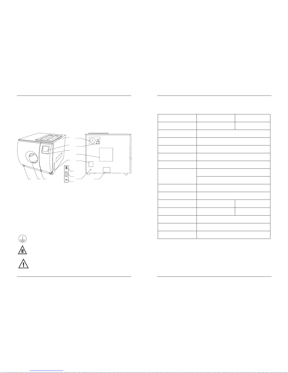
1 General
4
3
2
1
1 Distilledwater tank
2 LCDscreen
3 Controlpanel
4 Mainswitch
5 Drainconnector of distilledwater tank
6 Doorhandle
7 Drainconnector of usedwater tank
8 USBport (optional)
9 Printer port
10 Printer power
11 Bacteriological filter
12 Safety valve
13 Condenser ventilation
14 Circuit breaker
15 Power supplycord
16 Rating plate
In order to proper use the sterilizer, please be sure to read the
warning and attention carefully for safety.
Security Notice
This symbol is grounding protection inside the machine.
HOT SURFACE.
This symbol is visible on the front of the panel after open the door.
Important safety information.
This symbol is used to draw the attention of the reader to particularly
important notions for operator safety.
5
6
7
11
13
15
12
16
8
9
10
1
14
2 Technical Parameter
Chamber
Rated Voltage
Main Fuses
Nominal power (CLASS B)
Sterilization Temperature
Capacity of the distilled
water tank
Operation temperature
Outside size
Net weight CLASS B)(
Noise
Relative Humidity
Atmospheric pressure
Item
12
16
Φ230mmX360mm
Φ200mmX360mm
AC220V-240V(AC110V-130V), 50-60Hz
F16A/250V(F25A/250V for 110V)
2000VA
121 /134
℃℃
Approx 2.5L (water at level MAX)
Approx 0.5L (water at level MIN)
5-40
℃
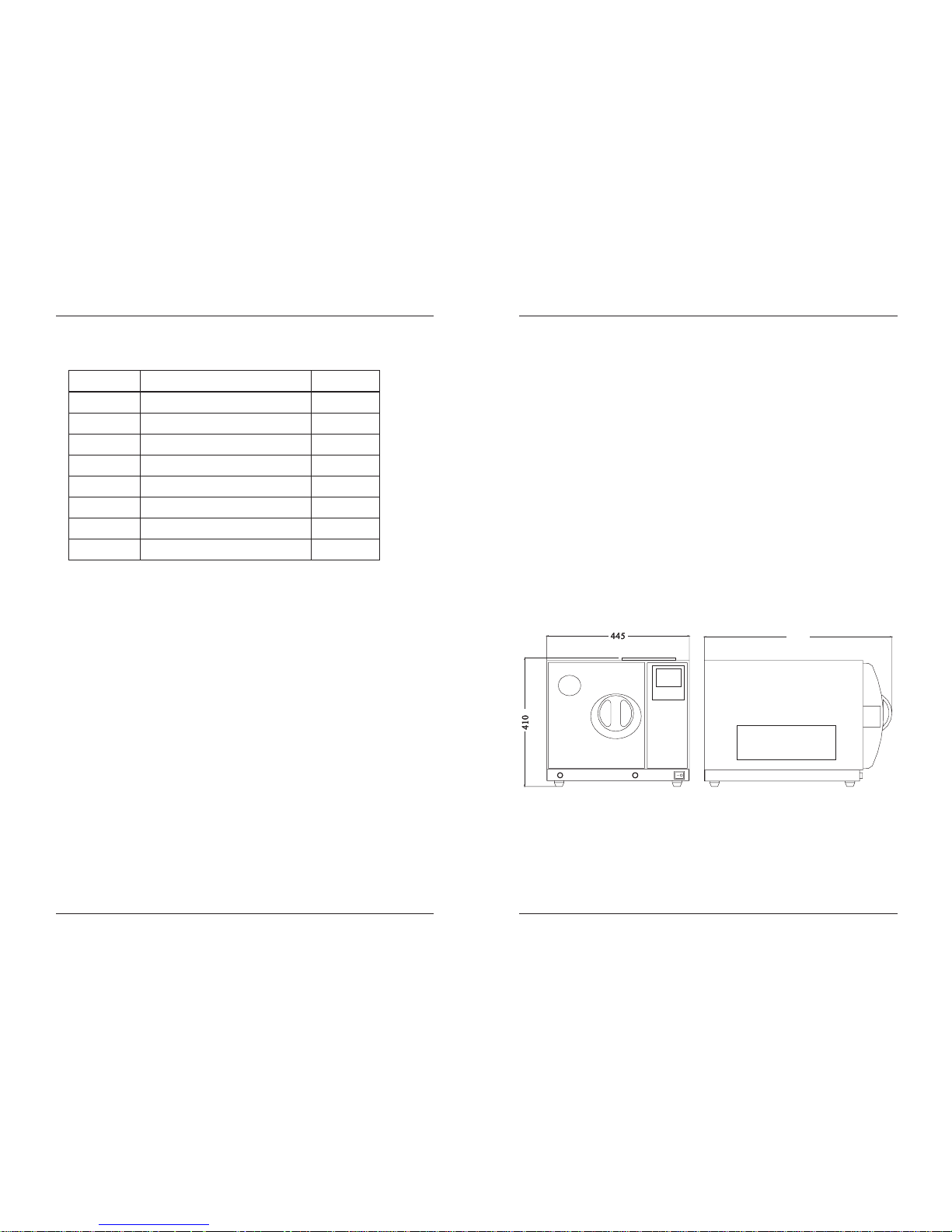
445mm(width)X 410mm(height)X 605mm(depth)
76kPa -106kPa
max. 80%, non condensing
<70dB
41kg
45kg
2
Nominal power (CLASS N)
1900VA
Net weight CLASS N)(
39kg
43kg
Instructions manual
Instructions manual
Page 4
3 Packing Content
Quantity
Item
No.
2
3
4
5
6
7
Instrument tray
Instrument tray rack
Instrument tray handle
Door adjustment tool
Draining hose
Instructions manual
2
1
1
1
2
1
1
1
Steam sterilizer
1
3
Door seal
8
4 Installation
* There must leaves 10cm gap around sterilizer, and 20cm on top side. the
clearance required for the movement of the door leave an at least
350mm fan-shaped space in front of the door.
* The place which sterilizer located must be ventilated,make sure that the
radiator not being jammed.
* The sterilizer should be placed on a levelworktable.
* Don't cover or block the door,ventilation or radiation openings on the
sterilizer.
* Don't place the sterilizer near a sink or in alocation where it is likely to
be splashed.
* Keep away from all sources of heat.
:
4
Instructions manual
Instructions manual
605
Page 5
Distilled water tank is lacking of water.
Distilled water tank is full
Used water tank is full.
Door locked
information output to USB port
Printer connect
Notice: Before using the sterilizer at the first start-up or any time the
icon blink, it is necessary to fill the distilled water tank
with distilled water.
5.1 Ready
5.1.1 Open the door and take out all the instrument trayand other
accessories inside, unpack and clean them.
5.1.2 Connect the power, and connect theprinter (See 6.5)
5.1.3 Power on
The switch is located underneath the control panel
on the front side of the machine .
After switching on, the machine turns on the LCD .
Then it will show the door position, water level,
working program, date, time and etc. .
The machine will alert by beep sounds if there are
problems.
5 Operation
Program
Alarm code
process curve
Temperature
Pressure
Setting
Time
Date
5
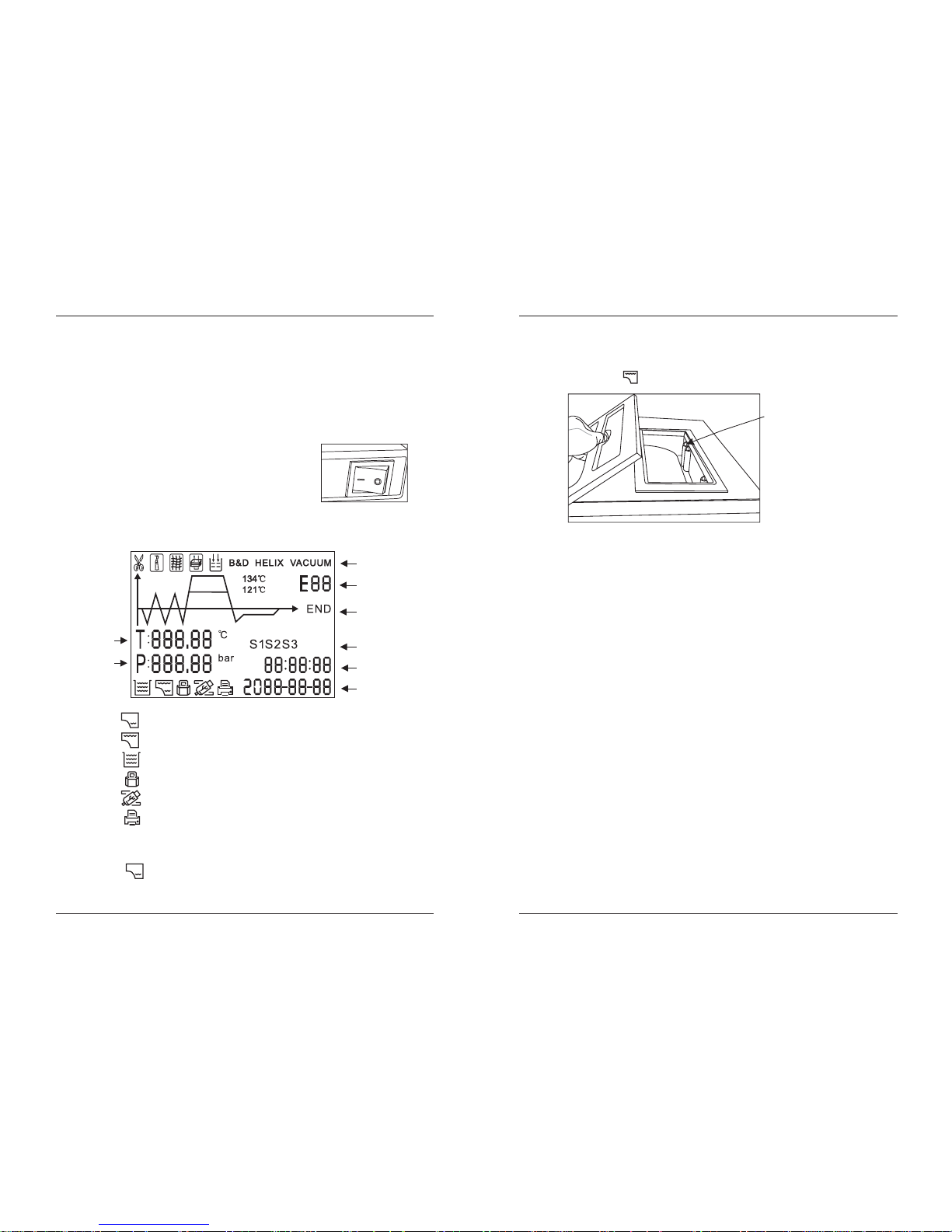
5.1.4 Filling the distilled water
Open the top lid, and fill the tank with distilled water by cup or tank.
When you hear a beep signal, it means the water level exceeds the
max. level. The will be displayed. Please stop filling immediately.
5.2 Preparing the material to be sterilized
To get thebetter effectiveness of the sterilization process andto preserve
the material in time, follow the indications below reported.
* Arrange the tools of different metal (stainless steel, moderate steel,
aluminum, etc.) on different trays or however well separate between them;
* In case of not stainless steel tools, interpose a sterilization paper napkin or
muslin cloth between tray and tool, avoiding direct contacts between the
two different materials;
* Verify all the tools aresterilized in open position;
* Arrange the containers (glasses, cups, test-tubes, etc.) on one side or
inverted position, avoiding possible water stagnation;
* Don't overload the trays over the stated limit (see Appendix 1).
* Don't stack the trays one above the other or put them in direct contact with
the walls of the sterilization chamber.
* Always use the instrument tray handle.
* Wrap the tools one by one or, if more tools have to be set in the same wrap,
verify that they are of the same metal;
*Seal the wrap with sterilization adhesive ribbon or by a thermal sealer.
* Don't use metallic clips, pins or other, as this jeopardizes the maintenance
of the sterility;
6
The waterlevel should not
exceeded thisport.
Instructions manual
Instructions manual
Page 6
* Turn the sterilization paper in order to set the plastic part downward
(tray side) and the paper part upward.
Always wrap the tools in case of prolonged store.
5.3 Selecting the sterilization program
5.3.1 LCD
It displays the cycle temperature,
pressure, error code, sterilization
state and program.
5.3.2 temperature button
Select temperature of sterilization.
5.3.3 Program button
Select program of sterilization.
5.3.4 START/STOP button
Press this button to start the sterilization cycle, holding this button above
3 seconds to stop the cycle.
5.3.5 Select the program
Press TEMP button to select the temperature. Andpress PROGRAM
button to select the program.
TEXTILE OR
DRYING
Notice: The button will be locked for 10 seconds after you switch on.
It initializes its system and check the states during that time.
7
8
SOLID
WRAPPED
(CLASS B)
(CLASS N)
5.4 Running the sterilization program.
After selecting program, put the
instruments into the chamber by tray
handle.
5.4.1 After the instruments are loaded, you
may close and lock the door by turning
the door handle clockwise until it stops.
The icon will be lightened.
Caution You must turn the door handle to the maximum position,
otherwise the machine will alarm and stop working
during the cycle.
:
Instructions manual
Instructions manual
SOLID
WRAPPED
PRION
LIQUID
B&D TEST
HELIX TEST
VACUUM TEST
DRYING
LIQUID
TEXTILE OR
DRYING
Page 7

Caution: When you press the "START” button but the door have not to be
closed. You will see the blinks on the screen, You can not
start a cycle until you close the door to the max. position and
press the "Start" button again.
9
5.4.2 Start the sterilization program.
Press START button the machine will begin the cycle automatically.
It will take 30-75 minutes. (See Appendix 2)
total time or
time count down
of holding time
and end time
total time or
time count down
of holding time
and end time
After a cycle is completed, the printer will start work and print the report
of the sterilization cycle data.(if you connect the printer)
After the pressure is 0, you may open the door, and take out the sterilized
instruments.
5.4.3 Sterilization cycle completion
Always use the tray handle to load or unload the tray in order to
avoid scald.
10
If you need the instrument urgently.You may set the drying time
to 0. It will skip the drying stage.
Or you may holding the START button for 3 seconds after finish
the holding time and the pressure is 0.
The program will go directly to the last step and skip the drying
stage. After one minute later it will show END.
(CLASS B)
(CLASS B)
(CLASS N)(CLASS N)
Instructions manual
Instructions manual
Page 8

6 Advanced Setting
6.1.1 Holding the STARTbutton and open the
main switch. After about 5 seconds it will
enter the setting screen.
6.1.2 Select the state by press PROGRAM button.
The state you selected will glitter.
Press the START button toenter the setting.
If you select the S1 and enter the state.
You maychange the unit of temperature and
pressure, adjust time and date.
6.2.1 You will select the unitof temperature first.
Press TEMP button to select or
The unit you select ed will be lighted. Press
the PROGRAM button to the next item.
6.2.2 You may set the pressureunit as the same
method.
6.2.3 Then press PROGRAM button to the next itemto adjust the time and
date. After the last word of the date or time is set , then the data is
permitted to be saved. If you want to finish the setting you shall press
START. It will return to the screen of selecting states.
6.1 Enter the setting
6.2 S1 state
℃.
If use this sterilizer on a place above 2 km, you need to reevaluate the
sterilization result. And you may correct the effect by prolong the
holding time.
The Machine No. And cycle No can not be set by the operator.
6.3 S2 state
6.3.1 You may check the count of sterilization
cycle. It can not be changed by operator.
6.3.2 Set the parameter for high altitude.
If you can't enter the holding time and use
this machine at a high altitude place that is
above 2.0 kilometers or atmospheric
pressure is below 80kPa you need set the
parameter. The scope is 0~2.
6.3.3 Language set:
00 English 01 German 02 Spanish
03 Polish 04 French 05 Magyar
06 Romanian 07 Dutch 08 Lithuanian 09 Latvian
cycle No
machine No
Altitude set
Language
set
12
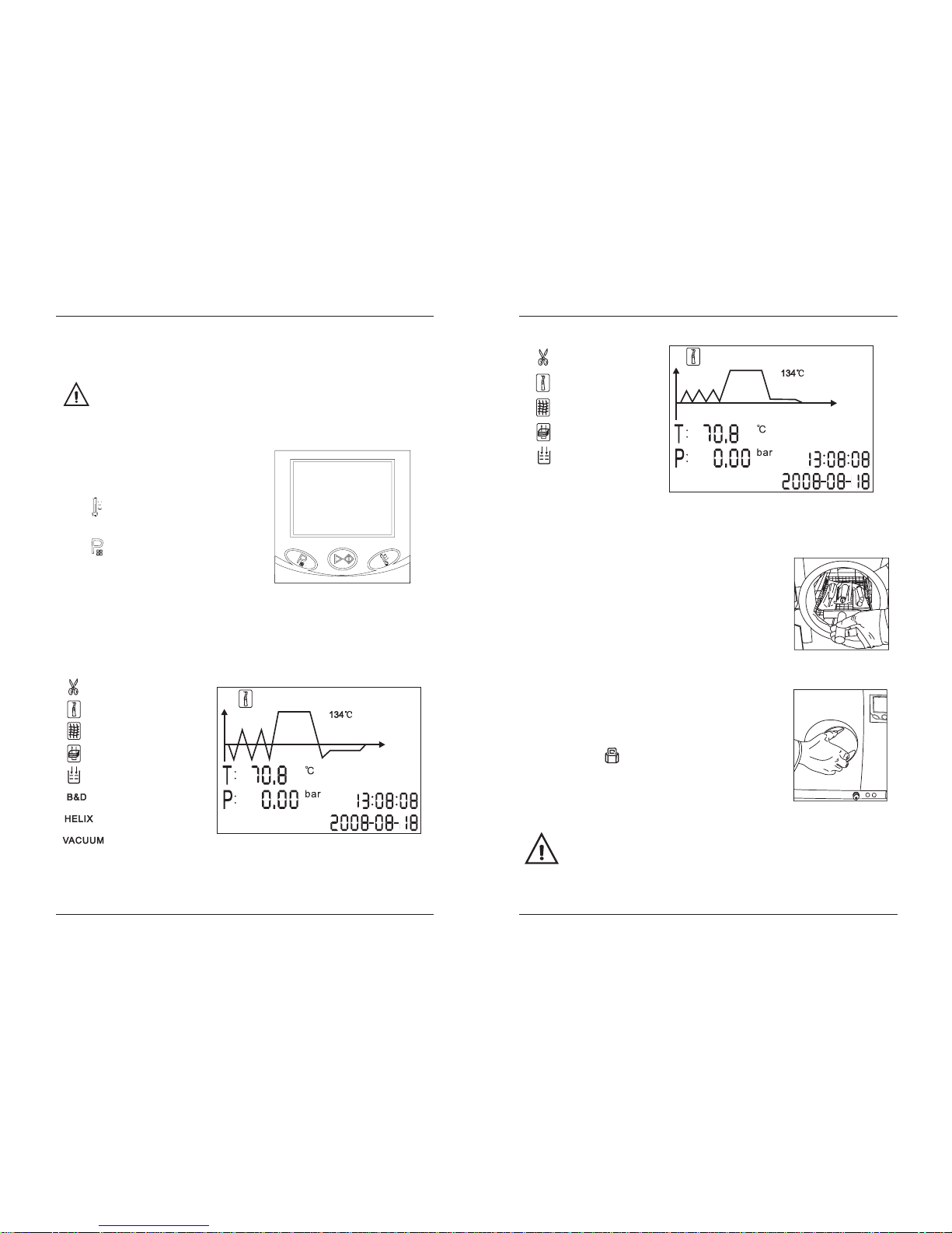
5.5 Test programs (CLASS B)
5.5.1 Press PROGRAM button, select the "B&D TEST".
5.5.1.1 Put the Bowie-Dick pack into the
chamber. Then close the door and
press "START".
5.5.1.2 After finish the cycle you check the
indicator. And evaluate the result.
5.5.2 Select the “HELIX TEST"
5.5.2.1 Put the indicator paper in the capsule.
5.5.2.2 Put the Helix tube into the chamber.
Then close the door and press
"START".
5.5.2.3 After finish the cycle you check the
indicator. And evaluate the result.
5.5.3Select the "VACUUM TEST"
5.5.3.1 Then close the door and press
"START" button.
5.5.3.2 After finish it will show the result.
5.5.3.3 In compliance with EN 13060, the
test requires the air leakage rate
less than or equal 0.13kPa/min
during the 10 minutes.
If the leakage rate is not greater 0.13,
it will show 0 means success.
Or it will show F means failure.
5.5.3.4 If the temperature deference between
the max. temperature and the min.
temperature is above 3, it will show
the value T on the screen and show F.
That means the result of test is void.
You needrun the vacuum test again
after the chamber has cooled down.
Caution: The VACUUM TEST must be
carried out with unit cold. If
the Tp is greater 3 , it will
show failure.
℃
leakage rate
temperature
deference
11
Instructions manual
Instructions manual
F
Page 9

6.5 Printer (Optional)
6.5.1 Connect the printer cable.
6.5.2 Connect the printer power.
holding time
drying time
Notice: We don't suggest the operator to adjust the parameter of
sterilization if it is not necessary.
6.4 S3 state
6.4.1 Adjust the holding time of sterilization and drying time.
Press PROGRAM button to select the program.( )
Press TEMP button to select the temperature of program.
Then press START to adjust thedrying time and holding time.
6.4.2 First to adjust the holding time.
Press TEMP button to adjust the data.
Press the PROGRAM button to select
the items.
6.4.3 Press START to save.
6.4.4 Drying time is 0-19.
Holding time of 121 is 1-59.
Holding time of 134 is 1-19.
℃
℃
13
12
t1 t 3 t5 t 8
t9
t2 t 4
t6
t7
ts
P
t
6.7 Record of the cycle
Select to this interface by PROGRAM button.
It will show cycle No. .
Select the different cycle No. by press
TEMP button.
It will output the information to printer and
USB port after you press START button.
It can be stored the last 20 records.
The sample of content of print and files in memory as below:
14
CLASS B
Instructions manual
Instructions manual
Insert the USB stick to the slot
The information will output to USB stick after the cycle finish
The name of the file is according to the number of machine and
the cycle number
For example
.
.
.
:
The machine number is E00001
The cycle number is 00012
The file name in the USB stick is 0 0 1200 txt
The first two numbers represent machine number
The middle four numbers represent cycle number
The last two numbers represent error code
00 no error 01 error E01
.
.
10 . .
.
.
.
:;:
6.6 USB Flash memory (Optional)
Page 10

15
=========================
Program: WRAPPED
Temperature: 134
Pressure: 210.0 kPa
Dry Time: 03Min
Ster Time: 4.0Min
------------------------------------time temp. pressure
Start 15:24:20 042.0
T1: 15:32:11 040.0 -78.2kPa
T2: 15:36:08 105.3 052.7kPa
T3: 15:39:21 061.3 -80.4kPa
T4: 15:44:32 110.3 051.6kPa
T5: 15:47:12 067.0 -80.4kPa
T6: 16:00:11 135.2 220.3kPa
TS: 134.8 221.6kPa
MAX.Temperature:135.5
MIN.Temperature:134.1
MAX.Pressure:230.4kPa
MIN.Pressure:212.9kPa
T7: 16:04:02 135.0 223.5kPa
T8: 16:06:32 92.8 -60.1kPa
T9: 16:09:22 90.4 -60.1kPa
End 16:14:12 78.2
--------------------------------------
Cycle No: 0005
Ster Value: Success
Date: 2011-01-18
SN:E00001
Operator:
=======================
℃
℃
℃
℃
℃
℃
℃
℃
℃
℃
℃
℃
℃
℃
℃
=========================
Program: WRAPPED
Temperature: 134
Pressure: 210.0 kPa
Dry Time: 03Min
Ster Time: 4.0Min
------------------------------------time temp. pressure
Start 17:34:20 042.0
T1: 17:42:11 040.0 -78.2kPa
T2: 17:46:08 105.3 52.7kPa
T3: 17:49:21 061.3 -80.4kPa
T4: 17:54:32 110.3 51.6kPa
T5: 00:00:00 000.0 000.0kPa
T6: 00:00:00 000.0 000.0kPa
TS: 000.0 000.0kPa
MAX.Temperature:000.0
MIN.Temperature:000.0
MAX.Pressure:000.0kPa
MIN.Pressure:000.0kPa
T7: 00:00:00 000.0 000.0kPa
T8: 00:00:00 000.0 000.0kPa
T9: 00:00:00 000.0 000.0kPa
End 17:54:42 100.2 010.1kPa
--------------------------------------
Cycle No: 0007
Ster Value: Failure E01
Date: 2011-01-18
SN:E00001
Operator:
=======================
℃
℃
℃
℃
℃
℃
℃
℃
℃
℃
℃
℃
℃
℃
℃
16
1
2
t1
T3
t5
t8
t2
t4
t7
ts
P
t
t6
=========================
Program: WRAPPED
Temperature: 134
Pressure: 210.0 kPa
Dry Time: 03Min
Ster Time: 4.0Min
------------------------------------time temp. pressure
Start 15:24:20 042.0
T1: 15:32:11 070.0 053.2kPa
T2: 15:36:08 075.3 009.7kPa
T3: 15:39:21 090.3 050.4kPa
T4: 15:44:32 094.3 009.6kPa
T5: 15:47:12 119.0 102.4kPa
T6: 16:00:11 110.2 009.3kPa
TS: 134.8 221.6kPa
MAX.Temperature:135.1
MIN.Temperature:134.5
MAX.Pressure:230.4kPa
MIN.Pressure:212.9kPa
T7: 16:04:02 135.0 223.5kPa
T8: 16:06:32 134.8 214.1kPa
End 16:14:12 78.2
--------------------------------------
Cycle No: 0005
Ster Value: Success
Date: 2011-01-18
SN:E00001
Operator:
=======================
℃
℃
℃
℃
℃
℃
℃
℃
℃
℃
℃
℃
℃
℃
=========================
Program: WRAPPED
Temperature: 134
Pressure: 210.0 kPa
Dry Time: 03Min
Ster Time: 4.0Min
------------------------------------time temp. pressure
Start 17:34:20 82.0
T1: 17:42:11 090.0 052.2kPa
T2: 17:46:08 085.3 009.7kPa
T3: 17:49:21 108.3 053.4kPa
T4: 17:54:32 100.3 009.6kPa
T5: 00:00:00 0 00.0 000.0kPa
T6: 00:00:00 000.0 000.0kPa
TS: 000.0 000.0kPa
MAX.Temperature:000.0
MIN.Temperature:000.0
MAX.Pressure:000.0kPa
MIN.Pressure:000.0kPa
T7: 00:00:00 000.0 000.0kPa
T8: 00:00:00 000.0 000.0kPa
End 17:54:42 100.2 010.1kPa
--------------------------------------
Cycle No: 0007
Ster Value: Failure E01
Date: 2011-01-18
SN:E00001
Operator:
=======================
℃
℃
℃
℃
℃
℃
℃
℃
℃
℃
℃
℃
℃
℃
CLASS N
Instructions manual
Instructions manual
========================
Program Vacuum test
Tp 1
P1 -70.0kPa
P2 -69.0kPa
rate of pressure rise 0.10
Start Time 08:22
End Time 09:01
Date 2011-01-18
Cycle No.:0001
TestValue Success
SN E00001
Operator
========================
:
:℃
:
:
:
:
:
:
:
:
:
Page 11

17
Replacing the bacteriological filter
(CLASS B)
Cleaning the external surface
Operation
Cleaning the door seal
Cleaning the reservoir
Cleaning the chamber
7.3 Replacement of the bacteriological filter
7.3.1 The bacteriological filter is at the back of
the sterilizer.
7.3.2 Unscrew the filter by hand (anti-clockwise).
7.3.3 Replacing the bacteriological filter.
7.3.4 Screw the new filter by hand clockwise.
Replacing the door seal
7.1 Clean the distilled water tank every
week with medical disinfectant .
7.2 Clean the chamber weekly.
7.2.1 Remove the trays and rock
from the chamber.
7.2.2 Clean the chamber with non-
plush cloth saturated with
distilled water.
7.2.3 Apply the same procedure for
the trays and rock.
Frequency
7. Maintenance
Every 3/6monthly
(depending onthe
use frequency)
7 Maintenance
Weekly
Every year
Daily
18
7.4 Clean the door seal
Clean the door seal weekly, with non-plush cloth saturated with the
distilled water.
Fig 1
Fig 2
Caution: Never try to readjust the chamber door while the door is locked
.
7.5 Door adjustment
On normal circumstance the chamber door lock don't need to adjust.
Once steam leaking occurs (the seal fails), you may use the spanner to
adjust door seal.
7.5.1 Open the door first
7.5.2 Insert the spanner in the gap beneath the plastic cover; use the spanner
to lock on the adjusting nut (Fig 1). Turn the nut counter clockwise as
the figure below (Fig 2). This will tighten the sealing plate.
7.5.3 Turn the nut until the sealing plate is tight. If the door knobis too tight,
you may also turn the nut clockwise to loosen it.
Instructions manual
Instructions manual
Page 12

19
7.6 Replacement of the door seal
7.6.1 Fully open the door.
7.6.2 Remove the door seal ring carefully by hand.
7.6.3 Clean the door seal ring carefully with a non-plush cloth
saturated with distilled water.
7.6.4 Moisten the new seal ring with medical disinfectant .
7.6.5 Insert the new seal ring and press in sequence as the
following.
Caution: Please ensure the chamber and the door has been cool
down before you replace the seal ring.
1). Pressthe up anddown of the
seal ring.
.
2). Pressthe left andright of the
seal ring
3). Pressthe left placeof the seal
ring cornerways.
4). Pressthe seal surfaceand make
it feelsmooth by finger.
20
8 Transportation and Storage
8.1 Switch off the sterilizer before transportation or storage. Pull out the
plug to let the machine cool down.
8.2 Drain the distilled water tank and the used water tank
8.3 Conditions for transportation and storage:
Temperature: -20 ~ +55
Relative humidity: 85%
Atmospheric pressure: 50kPa~106kPa
≤
7.7 The drain valve
1.Push the hose to the drain valve
by pressing it on firmly.
2.Set the drain valve to the open
position by turning it counter
clockwise.
3.Pull the drain valve outward, the
tank will begin to drain.
4.After finish draining the tank, push
the drain valve inward and turn
clockwise to the position .
Instructions manual
Instructions manual
Page 13

21
9 Error codes
Code
E1
E2
E3
E4
E5
E6
Description Proposed solution
Steam generator temperature
sensor error
Temperature sensor ofchamber
wall error
Inner temperature sensor error
Fail to rise temperature
Fail to release the pressure
Door has opened during the
cycle
Failure tohold temperature
Program manuallyinterrupted
Check the steam generator temperature
sensor
Check the inner temperature sensor
Check temperature sensor of chamber
Check the water release valve
Check the air release valve
Check the vacuum pump valve
Make sureyou have turned the doorhandle
to themax. Position orcheck the doorswitch
Shut off thepower and restart the
power
Ensure thedistilled water tankisn't empty
Check theinner temperature sensor
Check somewhereleaking
E13
E20
Vacuum failed (CLASS B)
Check thevacuum pump
E9
Failure topreheat the chamber
E12
E11
Failure topreheat the steam
generator
Check thesteam generator heater
Check thesteam generator protector
Check thechamber heater
Check chamberprotector
22
(1)Main fuses
Protection of the whole equipment against possible failures of the
heating resistor .
Action: Interruption of the electric power supply.
(2)Thermal cutouts on the mainstransformer windings
Protection against possible short circuit and mains transformer primary
winding overheating .
Action: Temporary interruption (up to the cooling) of the winding.
(3)Safety valve
Protection against possible sterilization chamber over-pressure .
Action: release of the steam and restoration of the safely pressure.
(4)Safety micro-switch for the doorstatus
Comparison for the correct closing position of the door .
Action: signal of wrong position of the door.
(5)Manually reset thermostat on chamberheating resistors
Protection for possible overheating of the chamber heating resistors .
Action: Interruption of the power supply of the chamber resistors.
(6)Manually rest thermostat on steamgenerator
Protection for possible overheating of the steam generator .
Action: Interruption of the power supply of the steam generator.
(7)Door safety lock
Protection against accidental opening of the door.
Action: Impediment of the accidental opening of the door during the program.
(8)Self-leveling hydraulic system
Hydraulic system for the natural pressure levelling in case of manual cycle
interruption, Alarm or black-out .
Action: automatic restoration of the atmospheric pressure inside chamber.
10 Safety devices
Instructions manual
Instructions manual
Page 14

23
APPENDIX 1
Characteristics of the feeding water
DESCRIPTION
FEED WATER
CONDENSATE
Evaporate residue
Silicium oxide sio
2
Iron
Cadmium
Lead
Rest ofheavy metals, excluding
iron, cadmium,lead
Chloride
≤10 mg/l
≤1mg/l
≤0.2 mg/l
≤0.005 mg/l
≤0.05 mg/l
≤0.1 mg/l
≤2mg/l
≤1.0 mg/kg
≤0.1 mg/kg
≤0.1 mg/kg
≤0.05 mg/kg
≤0.1 mg/kg
≤0.1 mg/kg
≤0.1 mg/l
Phosphates
Conductivity (at 20 )℃
pH value
Appearance
Hardness
≤0.02 mmol/l
Colorless, clean,
without sediments
575-.
≤μ15 s/cm
≤0.5 mg/l
≤0.1 mg/l
≤μ3 s/cm
57-
≤0.02 mmol/l
Colorless, clean,
without sediments
24
DIAGRAMS OF THE STERILIZATION PROGRAMS
APPENDIX 2
The time required for sterilizer to be ready for routine use after the power
is switched on less than 5 minutes.
The max. temperature of the 134 sterilization cycle is 137
The max. temperature of the 121 sterilization cycle is 124
℃℃
℃℃
Instructions manual
Instructions manual
HELIX TEST
PROGRAM
CLASS B()
SOLID
LIQUID
(Optional)
TEXTILE
(Optional)
PRION
DRYING
(Optional)
BDTEST&
VACUUM
TEST
Temperature
C()
134 210 4 14 30-
134 210 8 30 45-
134 210 18 35 55-
134 210 3 5 22 35.-
134 210 3 5 22 35.-
134 210 10 30 55-
121 110 30 35 60-
121 110 20 30 45-
121 110 30 30 50-
。
Pressure
kPa()
Holding time
min()
15 20-
Total time
min()
120-
Unwrapped porous material
Unwrapped porous material
Single wrapped porous
material
-
Single wrapped porous
material
-
Single wrapped hollow
material
-
Single wrapped hollow
material
-
Dual wrapped porous
material
-
Dual wrapped porous
material
-
Dual wrapped solid and
hollow material
-
Dual wrapped solid and
hollow material
-
Unwrapped solid
material
TYPE
Liquid
350 100..
350 100..
150 050..
150 050..
100 030..
075 020..
050 015..
Max Load.
400 120..
100 030..
100 030..
075 020..
050 015..
()kg
Max Load.
per tray kg()
WRAPPED
134 210 4 30 55-
121 110 20 35 60-
Unwrapped solid material
Single wrapped solid or
hollow material
-
350 110..
350..110
Page 15

25
-80
-70
00.
00.
100
100
200
200
SOLID
Pressure(kPa) Pressure(kPa)
Pressure(kPa) Pressure(kPa)
Time(min)
Time(min)
Time(min) Time(min)
-80
-80
200
200
00.
00.
100
100
WRAPPED
TEXTILE
PRION
DRYING
LIQUID
26
Instructions manual
Instructions manual
Page 16

27
-80
00.
100
200
Pressure(kPa)
Pressure(kPa)
Time(min)
Time(min)
VACUUM
TEST
200
100
00.
-.08
T1
T2
T3
P0 P1
P2
600s
B&D TEST
HELIX TEST
28
The time required for sterilizer to be ready for routine use after the power
is switched on less than 5 minutes.
The max. temperature of the 134 sterilization cycle is 137
The max. temperature of the 121 sterilization cycle is 124
℃℃
℃℃
Instructions manual
Instructions manual
PROGRAM
CLASS B()
SOLID
LIQUID
(Optional)
TEXTILE
(Optional)
PRION
DRYING
(Optional)
Temperature
C()
134 210 4 14 30-
134 210 8 30 45-
134 210 18 35 55-
134 210 10 30 55-
121 110 30 35 60-
121 110 20 30 45-
121 110 30 30 50-
。
Pressure
kPa()
Holding time
min()
Total time
min()
120-
Unwrapped porous material
Unwrapped porous material
Single wrapped porous
material
-
Single wrapped porous
material
-
Single wrapped hollow
material
-
Single wrapped hollow
material
-
Dual wrapped porous
material
-
Dual wrapped porous
material
-
Dual wrapped solid and
hollow material
-
Dual wrapped solid and
hollow material
-
Unwrapped solid
material
TYPE
Liquid
300 100..
300 100..
200 075..
200 075..
100 030..
075 020..
050 015..
Max Load.
400 120..
120 040..
100 030..
075 020..
050 015..
()kg
Max Load.
per tray kg()
134 210 4 30 50-
121 110 20 35 55-
WRAPPED
Unwrapped porous material
Single wrapped solidor
hollow material
-
400 120..
3.00 1 00.
Page 17

29
-.08 -.08
-.08 -.08
00. 00.
00. 00.
10. 10.
10. 10.
20. 20.
20. 20.
SOLID
Pressure(bar) Pressure(bar)
Pressure(bar) Pressure(bar)
Time(min) Time(min)
Time(min) Time(min)
30
WRAPPED
TEXTILE
PRION
DRYING
LIQUID
Instructions manual
Instructions manual
Page 18

31
APPENDIX 3
TP1: Steam generator temperature sensor
TP2: Inner temperature sensor
TP3: Temperature sensor of chamber wall
V1: Air release valve V4: Water release valve
V2: Air filter valve V5: Vacuum pump valve
V3: Water pump valve
ELECTRICAL DRAWING
ELECTRICAL DRAWING
TANKMAX. LEVEL TANK MAX.LEVEL
PRESSURE SENSOR
PRESSURE SENSOR
V1
V4 V4
V2
V3
V1
V5
PRINTER
POWER
PRINTER
POWER
-
+
KEYBOARD
DATALINE
KEYBOARD
DATALINE
DOOR CLOSE DOOR CLOSE
Tp1 Tp1
Tp2 Tp2
Tp3 Tp3
~ ~
~
230V(120V) 230V(120V)
230V(120)
VACUUM
PUMP
VACUUM
PUMP
~
~
9V(2.5A)
9V(2.5A)
~
~
9V(0.2A)
9V(0.2A)
~
~
21.5V
21.5V
~
~
0V
0V
FAN FAN
WATER
PUMP
WATER
PUMP
STEAM
HEATER
STEAM
HEATER
THERMAL
PROTECTOR
THERMAL
PROTECTOR
CHAMBER
HEATER
CHAMBER
HEATER
THERMAL
PROTECTOR
THERMAL
PROTECTOR
PUBLIC PUBLIC
TANKMIN. LEVEL TANKMIN. LEVEL
PRINTER
OUTPUT
PRINTER
OUTPUT
USB DATA
OUTPUT
USB DATA
OUTPUT
USED WATER TANK USED WATER TANK
32
TP1: Steam generator temperature sensor
TP2: Inner temperature sensor
TP3: Temperature sensor of chamber wall
V1: Air release valve
V4: Water release valve
230V (120)
-
+
()CLASS B
()CLASS N
Instructions manual
Instructions manual
Page 19

APPENDIX 4
HYDRAULIC DRAWING
33
V1: Air release valve
V2: Air filter valve
V3: Pump valve
V4: Water release valve
V5: Vacuum pump valve
Vacuum pump
V5
V3
Water pump
V1
V2
Safety valve
Air filter
Test
Port
V4
HYDRAULIC DRAWING
34
V1: Air release valve
V4: Water release valve
Chamber
Chamber
Pressure
sensor
Pressure
sensor
Safety valve
Pump
CondenserCondenser
Used water tank
Used water tank
Distilled water tank
Distilled water tank
()CLASS N
()CLASS B
Instructions manual
Instructions manual
 Loading...