

Page 1
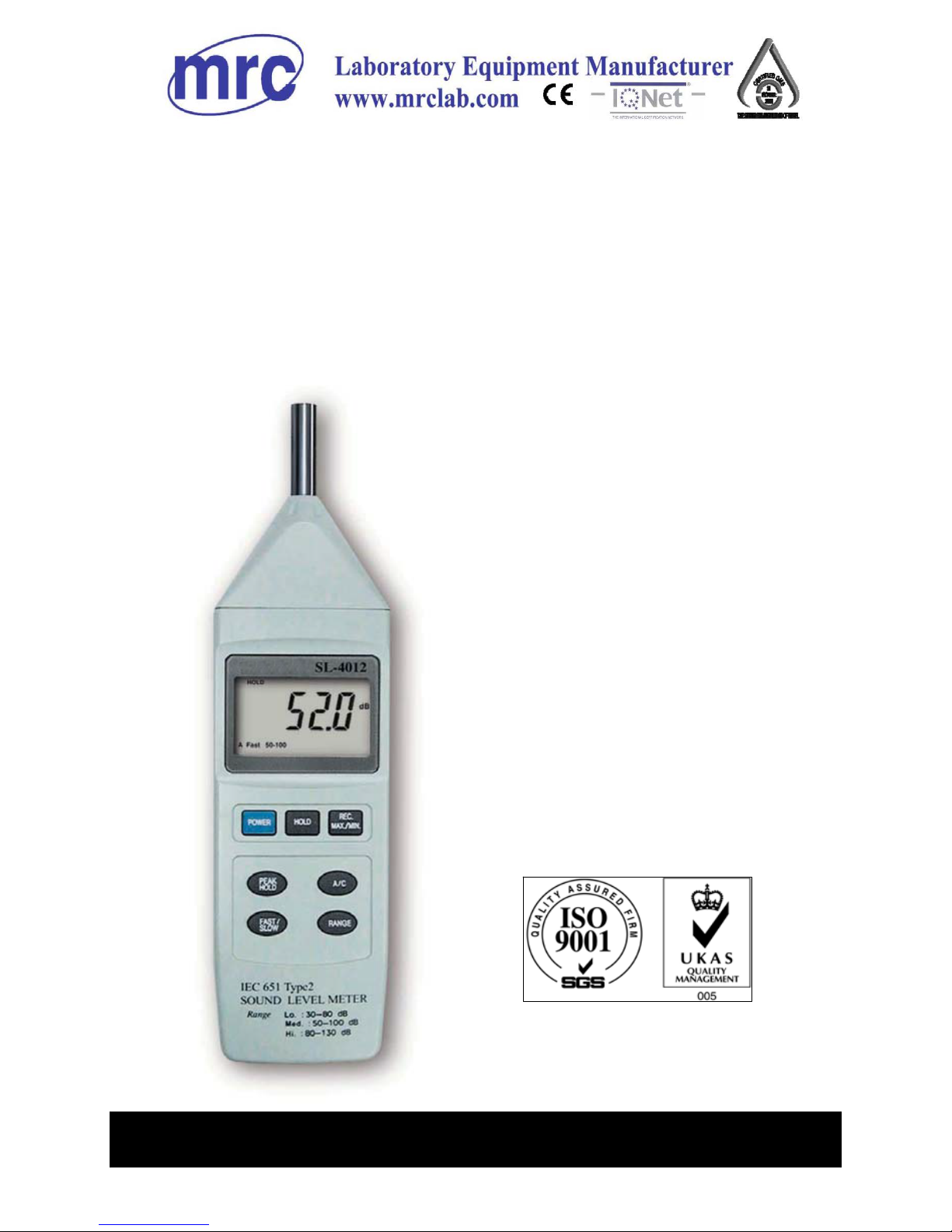
SOUND LEVEL
METER
Model : SL-4012
Your purchase of this
SOUND LEVEL METER
marks a step forward for
you into the field of
precision measurement.
Although this METER is a
complex and delicate
instrument, its durable
structure will allow many
years of use if proper
operating techniques are
developed. Please read
the following instructions
carefully and always keep
this manual within easy
reach.
OPERATION MANUAL
Page 2

TABLE OF CONTENTS
1. FEATURES................................................................1
2. SPECIFICATIONS......................................................1
3. FRONT PANEL DESCRIPTION....................................
.
4
3-1 Microphone....................................................... 4
3-2 Display..............................................................4
3-3 Power On/Off Button.........................................
.
4
3-4 Hold Button.......................................................4
3-5 REC./Max. Min. Button.......................................4
3-6 Max. Hold Button...............................................4
3-7 A/C Wei
g
hting Button.........................................4
3-8 Time Wei
g
hting ( Fast / Slow ) Button.................4
3-9 Ran
g
e Button....................................................4
3-10 AC Output Socket............................................
.
4
3-11 Calibration VR..................................................4
3-12 RS232 Computer Interface Socket....................
.
4
3-13 Battery compartment / Cover...........................
.
4
3-14 Stand..............................................................4
4. MEASURING PROCEDURES.......................................
.
5
5. AUTO POWER DISABLE............................................
.
8
6. MEASURING CONSIDERATION..................................
.
8
7. SIGNAL OUTPUT......................................................
.
8
7-1 AC output..........................................................
.
8
7-2 RS232 computer interface ........................................9
8. REPLACEMENT of BATTERY......................................
.
10
9. CALIBRATION .........................................................
.
10
10. FREQUENCY WEIGHTING CHARACTERI
STICS
OF A &
C NETWORKS.............................................11
11. TIME WEIGHTING (FAST & SLOW)
CHARACTER
ISTICS................................................
.
11
Page 3
1. FEATURES
* Large LCD display, easy to read.
* Main functions are designed to meet IEC 61672 class 2.
* A & C weighting networks comply with standards.
* 0.5" standard microphone head.
* Time weighting (Fast & Slow) dynamic characteristic
modes.
* AC output for system expansion.
* RS232/USB computer interface.
* Auto range & Manual range selection.
* Available for external calibration adjustment.
* Condenser microphone for high accuracy & long-term
stability.
* Memory function to store
the Max. & Min. value.
* Hold and MAX. Hold functions.
* Operation key used push button.
* LCD display for low power consumption & clear read-out
even in bright ambient light condition.
* Using the durable, long-lasting components, including a
strong, light weight ABS-plastic housing case.
* Small and light weight design allow one hand operation.
2. SPECIFICATIONS
Display 52 mm x 32 mm LCD (Liquid crystal
display), 5 digits with annunciator.
Function dB ( A & C frequency weighting ), Time
wei
g
hting(Fast, Slow), Hold, Memory
( Max. & Min. ), Max. hold, AC output,
RS232 output.
1
Page 4
Measurement 30 - 130 dB.
Ran
g
e
Resolution 0.1 dB.
Accuracy * Meet IEC 61672 class 2, tested under
(
23± 5
)
℃
Input signal level on 94 dB &
frequency ran
g
e from 31.5 Hz to
8 k Hz, refer to pa
g
e 11.
Range selector
Auto range :
30 to 130 dB.
Manual range :
3 range, 30 to 80 dB, 50 to 100 dB,
80 to 130 dB, 50 dB on each step,
with over & under ran
g
e indicating.
Frequency 31.5 to 8,000 Hz.
Microphone type Electric condenser microphone.
Microphone size Out size, 12.7 mm DIA. ( 0.5 inch).
Weighting Network Characteristics of A & C.
Range selector Manual range: 3 ranges ( 30 to 80 dB,
50 to 100 dB, 80 to 130 dB ).
Auto range: 30 - 130 dB.
Time weighting Fast - t= 200 ms, Slow - t = 500 ms,
( Fast & Slow ) * "Fast" range is simulated the
human ear response time.
* "Slow" range is easy to get the avg.
values of vibration sound level.
* The "Fast" & "Slow" response
range are designed to meet IEC 61672
class 2 requirement.
Calibrator B & K (Bruel & kjaer), MULTIFUCTION
ACOUSTIC CALIBRATOR 4226.
Output Signal
* AC output :
AC 0.5 Vrms corresponding to each
ran
g
e step.
Out put impedance - 600 ohm.
* RS232 output.
2
Page 5

Output terminal
Terminal 1 :
RS 232/USB PC serial interface.
* Connect the optional RS232 cable
UPCB-02 will
g
et the RS232 plug.
* Connect the optional USB cable
USB-01 will
g
et the USB plug.
Terminal 2 :
AC output terminal.
Terminal socket size :
3.5 mm dia. phone socket.
Calibration VR Build in external calibration VR, easy to
calibrate on 94 dB level by screw driver.
Operating Temp. 0 to 50 ( 32 to 122 ).℃℉
Operating Humidity Less than 80% RH.
Power Supply DC 9V battery, 006P, MN1604(PP3) or
equivalent.
*
Alkaline or heavy duty type.
Power Approx. DC 6 mA.
Consumption
Dimension 268 x 68 x 29 mm (10.6 x 2.7 x 1.1 inch).
Weight 285 g/0.63 LB (including battery).
Accessory Included Instruction Manual ............... 1 PC.
Optional
94 dB Sound Calibrator :
Accessories Model : SC-941. SC-942.
Sound wind shield ball
Model : SB-01
RS232 cable ( isolated RS232 cable ) :
Model : UPCB-02.
USB cable
Model : USB-01
Application windows software
:
Model : SW-U801-WIN.
3
Page 6

3. FRONT PANEL DESCRIPTION
Fig. 1
3-1 Microphone 3-9 Range Button
3-2 Display 3-10 AC Output Socket
3-3 Power On/Off Button 3-11 Calibration VR
3-4 Hold Button 3-12 RS232 Computer Interface
3-5 REC./Max. Min. Button Socket
3-6 Max. Hold Button 3-13 Battery compartment / Cover
3-7 A/C Weighting Button 3-14 Stand
3-8 Time Weighting ( Fast / Slow ) Button
4
Page 7

4. MEASURING PROCEDURE
1)Power on by pressing the " Power On/Off Button " ( 3-3,
Fig. 1 ) , the meter's default function is " Auto range ",
" A frequency weighting " & " Fast time weighting ". The
lower LCD display will show the unit " A. Fast Auto ".
2)
Select " A " or " C " frequency weighting by pressing the
" A/C Button " ( 3-7, Fig. 1 ) .
Note :
a. The characteristic table of A, C weighting, please
ref. page 11.
b. The characteristic of A weighting is simulated as
the " Human Ear Listening " response.
Typically always select the A weighting when makes
environmental sound level measurement.
c. The C weighting characteristic is near the " FLAT "
response. Typically it is suitable for checking the
noise of machinery ( Q.C. check ) & knowing the
real sound level of the tested equipment.
3)Determine proper measuring range by pressing the
" Range Button " ( 3-9, Fig. 1 ).
After power on the default range is " Auto range ".
In the same time the lower right display will show the text
of " Auto ".
Under the auto range, press the " Range Button " once
will enter to the manual range 1, range 2, rang 3. There
are still 3 manual ranges for your choice :
5
Page 8

*
Manual range 1 , 30 - 80 dB range :
Display will show the unit of " 30 - 80 ".
*
Manual range 2 , 50 - 100 dB range :
Display will show the unit of " 50 - 100 ".
*
Manual range 3 , 80 - 130 dB range :
Display will show the unit of " 80 - 130 ".
4) According to various measuring sound source, select the
Time Weighting ( Fast or Slow ) by pressing the " Time
Weighting Button " ( 3-8, Fig. 1 ).
Note :
a. If select the function of " Fast " time weighting, the
display will show the unit of " Fast ".
b. If select the function of " Slow " time weighting, the
display will show the unit of " Slow ".
5)Hold the instrument in hand and point the microphone at
measured noise source, the sound level value ( dB ) will be
displayed on LCD.
6)Max. Hold
If intend to maintain the maximum value, press
the " Max. Hold Button " ( 3-6, Fig. 1 ) and a " P.H "
symbol will show on the top LCD display. Press the
" Max. Hold Button again to exit the function.
Note :
a. When make the Max. Hold measurement under
slow varying noise environment, please select the
" Auto range "
b. When make the Max. Hold measurement under
pulse noise environment, it should select to the
convenient " manual range "
6
Page 9

7)Data Hold
During the measurement, pushing the " Hold Button "
( 3-4, Fig. 1 ) will hold the measured value & the LCD
will indicate " HOLD " symbol.
* Push the " Hold Button " again to release the data hold
function.
8)Data Record ( Max., Min. reading )
* The data record function displays the maximum and
minimum readings. To start the DATA RECORD
function, press the " REC. Button " ( 3-5, Fig. 1) once.
" REC " symbol will appear on the LCD display.
* With the " REC " symbol on the display :
a)
Push the " REC. Button " ( 3-5, Fig. 1 ) once, the
" REC Max " symbol along with the maximum value
will appear on the display.
If intend to delete the maximum value, just press
the " Hold Button " ( 3-4, Fig. 1 ) once a while, then
the display will show the " REC " symbol only &
execute the memory function continuously.
b)Push the " REC. Button " ( 3-5, Fig. 1 ) again, the
" REC Min " symbol along with the minimum value
will appear on the display.
If intend to delete the minimum value, just press
the " Hold Button " ( 3-4, Fig. 1 ) once a while, then
the display will show the " REC " symbol only &
execute the memory function continuously.
c) To exit the memory record function, push the
" REC " button at least 2 seconds continuously. The
display will revert back to the current reading.
7
Page 10

5. AUTO POWER DISABLE
The instrument has built-in " Auto Power Shut-off "
in order to prolong battery life. The meter will switch
off automatically if none of the buttons are pressed
within approx. 10 min.
To de-activate this feature, Select the memory record
function during measurement, by pressing the
" REC. Button " ( 3-5, Fig. 1 ).
6. MEASURING CONSIDERATION
1)Please should select the proper time weighting ( A
weighting or C weighting ). Typically the A weighting
selector will be engaged.
2)
Please don't keep or operate the instrument at high
temperature & humidity environment for a long period.
3)
Keep microphone dry & avoid serious vibration.
7. SIGNAL OUTPUT
7-1 AC output
The instrument is provided an 3.5 mm dia. phone socket
( 3-10, Fig. 1 ) for AC output, it is used to connect with
analyzer, level recorder, tape recorder, controller...etc.
Note :
AC 0.5 Vrms corresponding to each range step.
Output impedance - 600 ohm.
8
Page 11

7-2 RS232 computer interface
The instrument is provided an 3.5 mm dia. phone socket
( 3-12, Fig. 1 ) for RS232 computer interface socket.
The connector output is a 16 digits data stream which
can be utilized to the user's specific application.
A RS232 lead with the following connection will
be required to link the instrument with the PC
serial input.
Meter PC
(3.5 mm jack plug) (9W 'D" Connector)
Center Pin......................................Pin 4
Ground/shield....................................Pin 2
2.2
K
Pin 5 resister
The 16 digits data stream will be displayed in the
following format :
D15 D14 D13 D12 D11 D10 D9 D8 D7 D6 D5 D4 D3 D2 D1 D0
Each digit indicate the following status :
D15 Start Word
D14 4
D13 1
D12 & D11 Annunciator for Display
dB = 17
D10 Polarity
0 = Positive 1 = Ne
g
ative
9
Page 12

D9 Decimal Point(DP), position from right to the left
0 = No DP, 1= 1 DP, 2 = 2 DP, 3 = 3 DP
D8 to D1 Display reading, D1 = LSD, D8 = MSD
For example :
If the display reading is 1234, then D8 to D1 is :
00001234
D0 End Word
RS232 setting
Baud rate 9600
Parity No parity
Data bit no. 8 Data bits
Stop bit 1 Stop bit
8. REPLACEMENT of BATTERY
1)
When the left top corner of LCD display show " ",
it is necessary to replace the battery.
However within specification measurement may still be
made for several hours after low battery indicator appears
before the instrument become inaccurate.
2)Open the " Battery Cover " ( 3-13, Fig. 1 ) away from the
instrument and remove the battery.
3)Install a 9 V battery ( Alkaline or Heavy duty type ) and
replace the cover.
9. CALIBRATION
1)Prepare the optional " SOUND CALIBRATOR ", such
as " SC-941 " or " SC-942 ". Power on the Sound
Calibrator & plug calibrator output socket into the
" Microphone " head ( 3-1, Fig. 1 ) of the Sound Level meter.
2)Select manual range to " 50 - 100 dB ".
3)Select " Time Weighting " at " Fast " position.
4)Select " A " weighting.
5)Adjust the " Calibration VR " ( 3-11 ) carefully with a
" - " screw driver until the display reading value within
" 94± 0.2 " dB.
10
Page 13

10. FREQUENCY WEIGHTING
CHARACTERISTICS OF A and C
NETWORKS
Frequency A Weighting C Weighting Tolerance
Hz Charac. Charac. (IEC 61672 class 2)
31.5 -39.4 dB -3 dB ± 3.5 dB
63 -26.2 dB -0.8 dB ± 2.5 dB
125 -16.1 dB -0.2 dB ± 2.0 dB
250 -8.6 dB 0 dB ± 1.9 dB
500 -3.2 dB 0 dB ± 1.9 dB
1 K 0 dB 0 dB ± 1.4 dB
2 K +1.2 dB -0.2 dB ± 2.6 dB
4 K +1 dB -0.8 dB ± 3.6 dB
8 K -1.1 dB -3 dB ± 5.6 dB
11. TIME WEIGHTING ( FAST and
SLOW ) CHARACTERISTICS
Time Weighting Max. response Tolerance
Charac. ref. continuous signal (IEC 61672 class 2)
F ( Fast ) - 1.0 dB + 1 dB
- 2 dB
S ( Slow ) - 4.1 dB ± 2 dB
11
Hagavish st. Israel 58817 Tel: 972 3 5595252, Fax: 972 3 5594529
mrc@mrclab.com
MRC.5.16
 Loading...