

Page 1
Operation Manual for
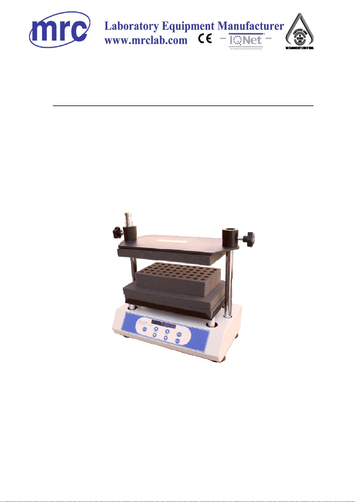
Multi-Tubbe Vortexer
SI-600
PLEASE READ THIS MANUAL CAREFULLY BEFORE OPERATION
3, Hagavish st. Israel 58817 Tel: 972 3 5595252, Fax: 972 3 5594529 mrc@mrclab.com
MRC.VER.01-8.12
Page 2

Foreword
Thank you for purchasing our Products: Multi-Tube Vortexer. This Manual
for users contains function and operation of the Instrument. In order to use
the instrument properly, please read this manual carefully before using the
Instrument.
Opening Check
Please check the Instrument and Appendix with the packing list when
you first open the instrument packing case. If you find there is something
wrong with the Instrument and the Appendix, do contact the vendor or the
producer.
Page 3
Safety Warnings and Guidelines
1. Important operation information of the security:
Before the users’ operation, they should have a perfect conception of how to
use the Instrument. Therefore, read this Manual carefully before using it.
2. Security:
The operation, maintenance and repair of the Instrument should comply with
the basic guidelines and the remarked warning below. If you don’t comply with
them, it will have effect on the scheduled using life of the Instrument and the
protection provided.
Operation before reading the Manual is forbidden. Read the
guidelines and directions below and carry out the countermeasure
according to them.
This product is a normal and an indoor Instrument which conforms
to Standard B style- I type- GB9706.1.
Before using the device, read the Manual carefully. These units are
designed for use in laboratory environments. The device must be used
by skilled personnel with the appropriate training.
The operator should not open or repair the Instrument by himself,
which will result in losing the qualification of repair guarantee or occur
accident. If there is some wrong with the Instrument, the company will
A.C. power’s grounding should be reliable to safeguard against an
electric shock. The 3-pin plug supplied with thermo-shaker’s power
cable is a safety device that should be matched with a suitable grounded
socket.
Page 4
Before power on, guarantee the voltage used should be accordant to
the voltage needed, and the rated load of electrical outlet should not
lower than the demand. If the electric line is damaged, you should
replace it with the same type. You should assure there’s nothing on the
electric line and you should not put the electric line in the ambulatory
place. Hold the jack when you pull out the electric line, and don’t pull
the electric line.
Power off when you finish your work. Pull off the connector plug
when there’s long time no use of the Instrument and cover it with a
cloth or plastic paper to prevent from dust.
Pull the connector plug from the jack at once in the following cases,
and contact the vendor:
There is some liquid flowing into the Instrument;
Drenched or fire burned.
Abnormal operation: such as abnormal sound or smell.
Instrument dropping or outer shell damaged.
The function has obviously changed.
3. The maintenance of Instrument
The platform and clamp should be cleaned by the cloth stained with a little
alcohol. If there are smutches on the Instrument, clean them by soft cloth stained
with cleaning cream.
Page 5

Contents
Chapter 1 Introduction ------------------------------------------------------------------------- 1
Chapter 2 Specifications ---------------------------------------------------------------------- 2
1. The normal operating condition --------------------------------------------- 2
2. The basic parameters and the function ----------------------------------- 2
Chapter 3 Preparations ------------------------------------------------------------------------ 3
1. Structure Description ----------------------------------------------------------- 3
2. Keyboard and Display panel ------------------------------------------------- 4
3. Power connection --------------------------------------------------------------- 5
4. Exchangeable Tube Foam Rack--------------------------------------------- 5
Chapter 4 Operation Guide ------------------------------------------------------------------- 6
1. Speed and time setting -------------------------------------------------------- 6
2. Key combination ----------------------------------------------------------------- 7
3. Pulsing mode-----------------------------------------------------------------------8
Chapter 5 Failure analysis and handling ------------------------------------------------ 9
ANNEX 1. Wiring Diagram for SI-600……………………………………………...10
Page 6

SI-600 Multi-tube Vortexer Chapter 1 Introduction
Chapter 1 Introduction
The Multitube Vortexer is designed for mechanical and chemical cell lysis,
mixing suspensions, and general sample agitation. This vortex mixer gives
a distinctly different motion than shaking a sample. With vortexing, greater
shearing forces are placed on materials in the bottom of a tube, thus
promoting either disruption or solubility.
The multi-tube vortex mixer is a tool to provide that extra degree of mixing,
however it accommodates full racks of tubes or microwell plates as
opposed to singe tubes. Consequently, this unit is useful for higher
throughput mixing of samples.
Features
•
LCD display, it is easy to setup and use.
•
Procedure restored function; when it power-down suddenly and then
re-power-on, the device can return to the set procedure automatically.
•
Timing function. It can be set mixing time within 00:00~99:59h,
display window shows the remnant time to do timing.
•
Brushless motor with precise speed, long-lifetime, and without
maintenance
─
1
─
Page 7

SI-600 Multi-tube Vortexer Chapter 2 Specification
Chapter 2 Specifications
1. The normal operating condition:
Ambient temperature::::4°°°°C ~~~~ 45°°°°C
The relative humidity: ≤70%
Power supply:::: AC100-240V 1.5A
2. The basic parameters and function
Model
Parameter
SI-600
Speed 500~2500rpm
Orbit 3.6mm
Time setting 1min ~ 99h59min
Max. load 4.5kg
Input power 60W
Outer dimension(mm)
Weight(kg) 14.5
426×250×480
─
2
─
Page 8

SI-600 Multi-tube Vortexer Chapter 3 Preparations
Chapter 3 Preparations
This chapter introduces Multi-Tube Vortexer’s mechanical structure and the central
panel’s functions and some preparations before power-on. You should be familiar with
this chapter before the Multi-Tube Vortexer is first operated.
1. Structure Description
Support plate
Screw knobs
Foam tube rack
Panel
─
3
─
Mains power supply
Power connector
USB input interface
Page 9

SI-600 Multi-tube Vortexer Chapter 3 Preparations
2.
Keyboard and Display panel
Short
Start
Short mix key: the machine mixes in the highest speed by
pressing this key continuously, and will stop running when leaving
go of it.
Start key, short pressing this key to start the procedure
Stop
Stop key, short pressing this key to start the procedure
Increasing key for speed and time, it can setup speed and time
Decreasing key for speed and time, it can setup speed and
time
─
4
─
Page 10

SI-600 Multi-tube Vortexer Chapter 3 Preparations
3. Power connection
Place the Multi-Tube Vortexer on a level bench or table. Plug the extend power supply
unit into the socket at the rear side of the machine. The external power supply unit
(power adapter AC100-240V) ensures the external safety of the unit.
AC100-240V~
4. Exchangeable Tube Foam Rack
Type Parameter Tube Capacity Dimension (mm)
SI-B01 10mm 50 245X132X45
SI -B02 12mm 50 245X132X45
SI -B03 13mm 50 245X132X45
SI -B04 16mm/15ml 50 245X132X45
SI -B06 25mm 15 245X132X45
SI -B07 50ml 15 245X132X45
SI
–B00
Replacement tray
pad set
─
5
─
/ 305X178.5X25
Page 11

SI-600 Multi-tube Vortexer Chapter 4 Operation Guide
Chapter 4
Operation Guide
1. Shaking speed and timing setting
a) When the instrument powers on, display screen
will show “ ” one by one with the sound of
“du…”. The instrument goes into the initial state
after it flicks three times.
b) After about 2s later, time display window shows
9: 30 as the
set timing time. It means that the timing time is 9
hours and 30 minutes. The speed display
window shows 2000. It means the set shaking
speed is 2000rpm.
rpm
8888
8888 88:88
88888888
2000
2000 09:30
20002000
rpm
88:88
88:8888:88
09:30
09:3009:30
h/m
m/s
h/m
c) Press speed’s “” or “” key, tens digits of set
value will increase or decrease, and also increase
or decrease in hundred digits and thousand digits.
For instance, press the key and hold on for 2s, the
digits will be moved from tens to hundreds,
increasing the alteration range.
d) Press time’s “”or “” key, units will increase or
decrease, and also increase or decrease in tens,
hundreds and thousands. For instance, press the
key and hold on for 2s, the digits will be moved
from units to tens, increasing the alteration range.
If you press the key for 2s again, the digits will be
moved from tens to hundreds quickly.
2000
2000 09:30
20002000
2000
2000 09:30
20002000
rpm
rpm
09:30
09:3009:30
09:30
09:3009:30
h/m
h/m
─
6
─
Page 12

SI-600 Multi-tube Vortexer Chapter 4 Operation Guide
e) If you want to set speed 2400rpm and timing
2hours, press Speed’s “” key, and the set value
will be increase to 2400rpm. Keep off the key, the
device will save the value automatically. Then
press time’s “” key, the set value will be
decreased to 02:00; keep off the key, the device
will save value automatically. In this way, the
speed and time are set. Press the key “start”, the
device will run in 2400rpm and 2hours timing.
2. Key combination
a) Time unit switch mode: Press time’s “” key and
“” key simultaneously to switch time unit from
h/m to m/s, flicks three times, then save
automatically. The way to switch from m/s to h/m
is the same to above.
2400
2400 09:30
24002400
2400
2400 02:00
24002400
2400
2400 02:00
24002400
2400
2400 02:00
24002400
rpm
rpm
rpm
rpm
09:30
09:3009:30
02:00
02:0002:00
02:00
02:0002:00
02:00
02:0002:00
h/m
h/m
h/m
m/s
b) Key lock function: Press speed’s “” key and
time’s “” key simultaneously to activate the key
2400
2400
lock funtion. The key lock prevent from setting time
and speed during a mixing operation. When open the
key lock, you can set the parameters again. After
setting, the parameters in display flicks three times
and saves the changes automatically.
Notice: During running the device, neighter Shortcut Keys nor Key combination can be
opened.
24002400
2400
2400 02:00
24002400
rpm
rpm
02:00
rpm
02:00
02:0002:00
02:00
02:0002:00
m/s
m/s
─
7
─
Page 13

SI-600 Multi-tube Vortexer Chapter 4 Operation Guide
4. Pulsing mode
a)
Press “Stop” and “Short” key simultaneously
into pulsing mode, then the sign disappear
and red light is on.
b) Press Speed’s or Time’s “” key and “” key to set
the pulsing speed and time. In pulsing mode, the max.
timer time is 99min59sec.
c) If we set the pulsing time is 20 seconds, then press
“Start” key to run, it will pulse-on and pulse off times
with 20 seconds in 1 second intervals.
d) Press “stop” key to stop.
e) Press “Stop” and “Short” key simultaneously again
to quit the pulsing mode, then the sign display
again and red light is off.
2400
2400 02:00
24002400
2400
2400 0
24002400
2400
2400 02:00
24002400
rpm
rpm
rpm
02:00
02:0002:00
0
0000000::::2222000
02:00
02:0002:00
m/s
m/s
m/s
─
8
─
Page 14

SI-600 Multi-tube Vortexer Chapter 5 Failure analysis and handling
Chapter 5 Failure analysis and handling
Failure analysis and processing procedures
No. Phenomenon Cause Remedy
No power
No display
1
Shaking too big
2
The actual speed is different
3
from the displayed speed
“ERR” in the display
4
Press invalid Press-key failure
5
Switch Failure Exchange the switch
Others Contact the seller
Mixing samples are
placed asymmetrically
Failure in control board Contact the seller
Shaking speed is out
of control
Check the connection of
power
Place the mixing samples
symmetrically
Contact the seller
Contact the seller
─
9
─
Page 15

SI-600 Multi-tube Vortexer Annex 1
Annex 1::::Wiring Diagram for
Multi-Tube Vortexer
AC100V ~ AC240V
LPEN
Earth
L
N
PE
24V-
24V+
J2J3DC24V
SI-600
Motor
MOTER
Main Board
Key and display
PORT1
Key and display
─
10
─
 Loading...