

Page 1
RS232 to WiFi CONVERTER
Model : RHW-925
Your purchase of this
RS232 to WiFi
CONVERTER marks a
step forward for you
into the field of
precision measurement.
Although this Meter is a
complex and delicate
instrument, its durable
structure will allow
many years of use if
proper operating
techniques are
developed. Please read
the following
instructions carefully
and always keep this
manual within easy
reach.
OPERATION MANUAL
PLEAS
E READ THIS MANUAL CAREFULLY BEFORE OPERATION
Hagavish st. Israel 58817 Tel: 972 3 5595252, Fax: 972 3 5594529 mrc@mrclab.com
MRC.11.17
Page 2

TABLE OF CONTENTS
1. FEATURES................................................................................................................................................................
1
2. SPECIFICATIONS..........................................................................................................................................................
2
3. FRONT PANEL DESCRIPTION.......................................................................
4
4. MEASURING PROCEDURE................................................................................
5
4-1.The initial startup screen....................................................................................................................
5
4-2.Measuring and setting screens...........................................................................................
5
4-3.The summary description of keyboard..........................................................................................................
6
4-4.Setting Description.....................................................................................................................
6
4-5.Set value storage.....................................................................................................
8
4-6.Mesurement and WiFi connection........................................................................................
8
4-7.Reply factory setting......................................................................................................
8
4-8.AP Mode.......................................................................................................
9
4-9.Client Mode (internal network) ...........................................................................................................
12
4-10.Client Mode(External network fixed IP)...................................................................................................
12
4-11.Client Mode(External network floating IP).............................................................................................
14
4-12.Ethernet Mode connecter network floating (intenal network ).............................................................................................
16
4-13.Ethernet Mode connecter network floating (extenal network ).............................................................................................
16
4-14.Ethernet Mode is connected via the wireless bridge network.............................................................................................
16
4-15.Ethernet Mode is connected via the wireless bridge network .............................................................................................
17
4-16.RS232 Function SERIAL OUTPUT.............................................................................................
19
Page 3

1. FEATURES
* Can be temperature and humidity data sent to the desired device through WiFi.
the use of smart phones or tablet computers developed by the company's free
software to do data collection record APP.
* WiFi work mode: Access Point(AP) or Client mode
* I/O terminal:
1.DC 9V power input
2.DC 9V power output(power supply for the connecting RS232 meter)
3.Pt-100 ohm input.
4.Three RS232 input(photo isolate RS232 type)
3.Ethernet RJ485 input.
* Basic setting:
1.NetMode, 2.SSID, 3.Password, 4.IP address, 5.Port,
6.Gateway address,
* Simultaneous display Humidity ,Temperature,Web buie, Dew point temp.
reading value.
* Humidity range : 5% to 95%
*
Temprature range : 0 ℃ to 50 ℃, ℃/℉
* Maximum TCP connections to 20
* Without going through the computer settings, can be used directly
after the machine settings
1
Page 4

2. SPECIFICATIONS
Circuit Custom single-chip microprocessor LSI circuit
Display LCD Size: 3.2 X 2.4” (60 X 44.4 mm)
Dot Matrix backlit LCD (128 X 64 pixels)
Wireless * Support IEEE 802.11b / g / n wireless standards
* Support the range of frequency : 2.412 to 2.484 GHz.
* Support two types of wireless networks: Access
Point(AP) and Client
* Support multiple security authentication mechanisms :
64/128/152 bit WEP encryption, WPA-PSK/
WPA2-PSK、、WPA/WPA2 security mechanism.
NET mode
* Access Point (AP) Mode(Wireless)
setting
* Client Mode(Wireless)
* Ethernet Mode(RJ45)
Measurement * Humidity/ Temperature
* Dew pint Temperature
* Wet bulb Temperature
* Pt 1000 ohm Temp.
Data Output
RS232 computer serial interface
USB/RS232
* Connect the optional USB cable USB-01 will get the
*Computer
USB plug.
interface
* Connect the optional RS232 cable UPCB-02 will get the
RS232 plug.
Operating
0 to 50℃ ( 32 to 122℉ ).
temperature
Operating Less than 80% R.H..
humidity
Power supply AC to DC adapter 9V.
Power DC 170 mA approximately.
consumption
Weight 222 g/0.49 LB.
Dimension 134 X 80 X 32 (5.3 X 3.1 X 1.3 inch).
* Dimension is for the meter without antenna only.
2
Page 5

Accessories
* Instruction manual......................................................
1PCS
included
* Hanging unit ( with sticker ).........................................
1PCS
* AC to DC 9V power adapter.....................................
1PCS
Optional * RS232 cable,UPCB-02.
Accessories * Pt 1000 Temp. probe,TP-1000
* USB cable,USB-01.
* Data Acquisition software,SW-U801-WIN.
* Power interface cable, PWCB-06
2-2.Electrical Specifications (23 ± 5 ℃)
Humidity
Range Resolution Accuracy
5 % to 95 %RH 0.1 %RH < 70 %RH: ± 3 %RH
≧70 %RH: ±(3 %RH reading + 1 %RH)
Temperature
Range Resolution Accuracy
0.0 ℃ to 50.0 ℃ 0.1 ℃ ± 0.8 ℃
32.0 ℉ to 122.0 ℉ 0.1 ℉ ± 1.5 ℉
Dew point Temp.
Range Resolution Accuracy
-25.3 ℃ to 49.0 ℃ 0.1 ℃ Calculate from the
-13.5 ℉ to 120.0 ℉ 0.1 ℉ Humidity/Temp. Value
Wet bulb Temp.
Range Resolution Accuracy
-5.4 ℃ to 49.0 ℃ 0.1 ℃ Calculate from the
22.2 ℉ to 120.0 ℉ 0.1 ℉ Humidity/Temp. Value
Pt 1000 ohm Temperature(optional probe)
Range Resolution Accuracy
-10.0 ℃ to 70.0 ℃ 0.1 ℃ ± 1.2 ℃
14.0 ℉ to 158.0 ℉ 0.1 ℉ ± 2.5 ℉
3
Page 6
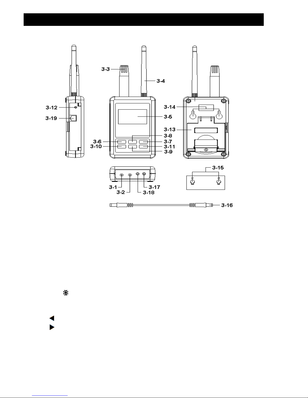
3. FRONT PANEL DESCRIPTION
Fig. 1
3-1 DC 9V Power adapter input socket
3-2 DC 9V output socket
3-3 Humidity/Temp. sensor
3-4 Antenna and antenna socket 3-12 System reset button
3-5 Display 3-13 Stand
3-6 SETUP/ENTER KEY 3-14 Hanging holes
3-7 EXIT( ) key button 3-15 Hanging unit ( with sticker )
3-8 ▲ key button
3-16 Power interface cable/plugs
3-9 ▼ key button
3-17 Isolate RS232 output socket
3-10 key button 3-18 Pt1000 input socket
3-11 key button 3-19 Network socket(RJ45)
4
Page 7
4. MEASURING PROCEDURE
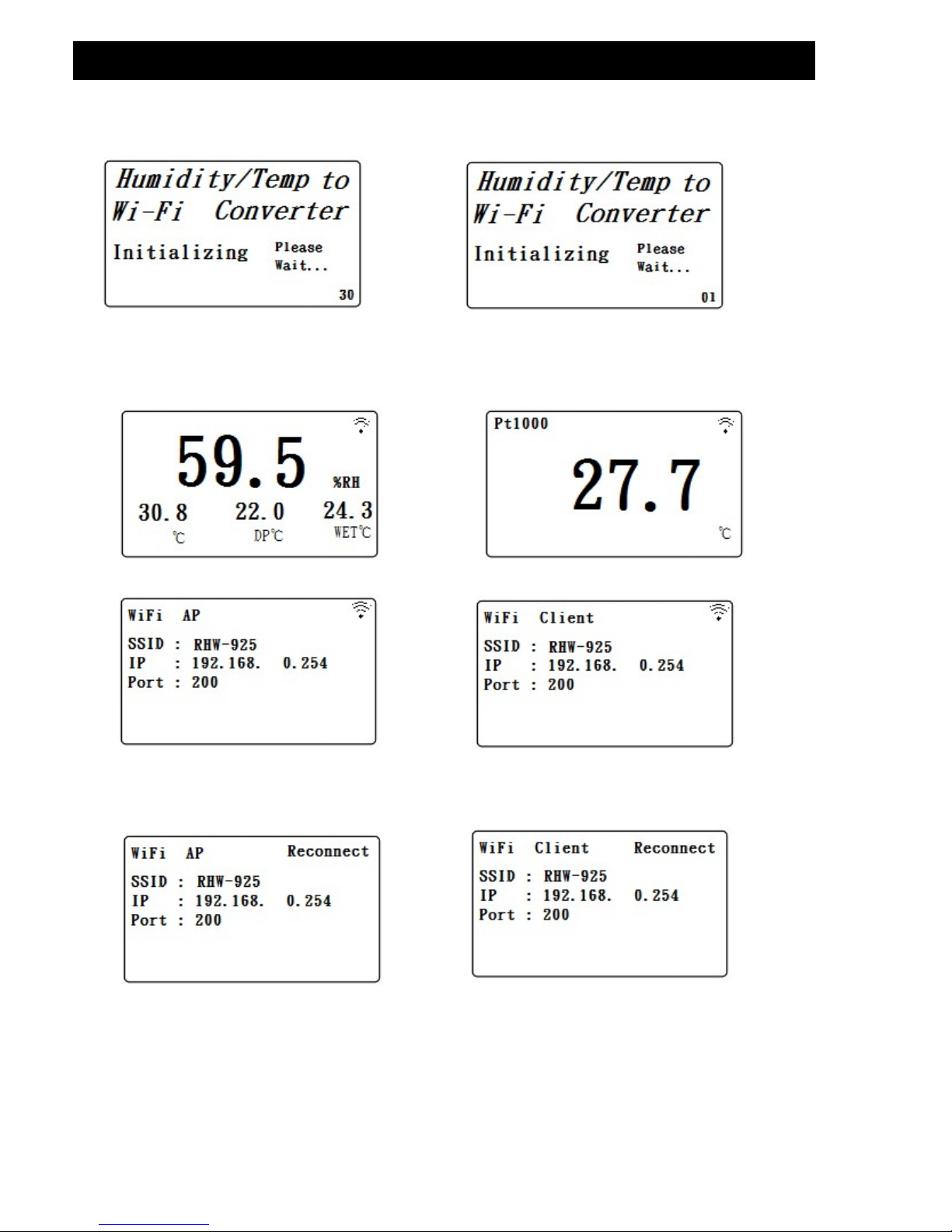
4-1.The initial startup screen
SCREEN4-1-1 SCREEN4-1-2
4-2.Measuring and setting screens:
1.Measurement screen:
SCREEN4-2-1 SCREEN4-2-2
SCREEN4-2-3
SCREEN4-2-4
SCREEN4-2-5 SCREEN4-2-6
5
Page 8

2.Setting screen:
SCREEN4-2-5 SCREEN4-2-6
4-3.The summary description of keyboard:
1.SETUP(Enter) KEY: Setting screen into the select key
2.In the setting mode:
2-1.Press ▲ or ▼ to select the field in the upper and lower beating
2-2.▲ or ▼ > 2 SEC.: The selected field will rapidly beating
2-3.▲ + ▼ > 2 SEC.: Then the entire column cleanup
2-4.Press ▲ KEY hold short press ▼ KEY and the right of the text
will be cleared
2-5. 、 KEY: Left and right keys
2-6.EXIT/SHIFT( ) KEY: Press key text input type selection or
setting screen left
3.In the measurement mode:
3-1.In Easy mode, press ▲ + ▼ > 2 SEC. Then turned into full mode
3-2.In full mode, press ▲ + ▼ > 2 SEC. Then becomes easy mode
3-3.EXIT/SHIFT( ) KEY: Backlight control key
4-4.Setting Description:
1.When the POWER ON, then enter the startup screen countdown 30 SEC.
(SCREEN4-1-1 & SCREEN4-1-2) to 0 SEC. Then enter the measurement
screen (SCREEN4-2-3 or SCREEN4-2-4).
2.Press SETUP KEY once you enter the setup screen as SCREEN4-2-7 or
SCREEN4-2-8
3.In the function directory option Press ▲ or ▼ KEY, functional directory
option will flash.
4.Press or KEY into the content selection function directory option
(in this case will flash), After selecting the complete press SETUP KEY
Then back to the function directory option to determine the setting options
5.Function directory:
6
Page 9

5-1.NetMode: Select AP or Client, the factory setting is Client.
A. Enter this option, then press or KEY contents into the option,
then press ▲ or ▼ KEY to select AP or Client, After determining
Press SETUP KEY do confirm the contents, then will return to
NetMode directory
B. Press ▼ KEY into the SSID option from NetMode
5-2.SSID: The default setting is RSW-925
A. Enter up to 21 characters
B. Press or KEY then enter the option contents, then press ▲
or ▼ KEY to select the input text, press EXIT / SHIFT KEY select
words in English caseor numbers. Determined by SETUP KEY do
confirm the contents, then will return to the SSID directory.
C. Press ▼ KEY into the Encrypt option from SSID
5-3.Encrypt:The default setting is none
A. none/wep_open/wep/wpa_tkip/wpa_aes/wpa2_tkip/wpa2_aes/
wpawpa2_tkip/wpawpa2_aes total of nine
B. After pressing
▲
or ▼ KEY select the option by the need, press
SETUP KEY to confirm, then will return to Encrypt directory
C.Press
▼
KEY into the Password option from Encrypt
5-4.Password: The default setting is 12345678
A. Press or KEY then enter the option contents, then press
▲
or ▼ KEY to select the input text, press EXIT / SHIFT KEY select
English words large, lowercase and numbers Press SETUP KEY
do confirm the contents, then will return to Password directory
B. Press
▼
KEY into the IP option from Password
5-5.IP: The default setting is 192.168.0.254
A. Press or KEY then enter the option contents, then press
▲
or ▼ KEY to select the number, press the SETUP KEY The
contents do confirm, then will return to the IP directory
B. Press
▼
KEY into the Port option from IP
5-6.Port: The default setting is 200
A. Input Range:1-65535
B. Press or KEY then enter the option contents, then press ▲
or ▼ KEY to select the number, press the SETUP KEY The
contents do confirm, then will return to the Port directory
C. Press
▼
KEY into the Gateway option from Port
7
Page 10

5-7.Gateway: The default setting is 192.168.0.1
A. Press or KEY then enter the option contents, then press
▲
or ▼ KEY to select the number, press the SETUP KEY The
contents do confirm, then will return to the Gateway directory
B.Press
▼
KEY into the Meter CH.option from Gateway
5-8.UNIT:
A. Press or KEY once,into the UNIT Choice, then use
▲
or ▼ Key to
select
℃
or ℉, then press SETUP Key back to UNIT Choice.
B. Press
▼
KEY into the Default Settings option from Meter CH.
5-9.Default Settings: Reply factory setting (refer NO.4-7)
4-5.Set value storage:
Press EXIT / SHIFT KEY save settings, and return to the measurement
screen, such as SCREEN4-2-5 or SCREEN4-2-6. This time to reconnect
after about 25 SEC WiFi is doing set after, then back SCREEN4 -2-3 or
SCREEN4-2-4 screen.
4-6.
Mesurement and
WiFi connection:
A. In SCREEN4-2-1 is Tempereture and Humidity mesurement Function screen.
B. Pt1000 mesurement Function:
1) Pt1000 probe insert to Fig.1 3-18.
2) In SCREEN4-2-1, press Key once ,into Pt1000 mesurement scree
(as SCREE 4-2-2),then press Key again,will back SCREE 4-2-1.
3) SCREE 4-2-3 or SCREE 4-2-4 upper right corner Symbol flashes, that WIFI
connection is ok.
4-7.Reply factory setting
1.Press SETUP KEY once you enter the setup screen as SCREEN4-2-7 &
SCREEN4-2-8
2.Press ▲、▼ KEY select the option to Default Settings item, press KEY
once you enter N option, press ▲ or ▼ KEY select Y press Enter KEY
,will return to directory option then press EXIT / SHIFT KEY will return to
factory default action to do its screen will SCREEN4-2-5 or SCREEN4-2-6,
after about 25 SEC later. would return SCREEN4-2-3 or SCREEN4-2-4.
8
Page 11

4-8.AP Mode:
1.First, install lutron dedicated APP software
1-1.The use of smart phone Andriod or iOS system software download
Lutron MeterApp (SCREEN4-8-1), Andriod Password: Az6210
,iOS Password: aZ6210.
1-2.After the download is complete, install it.
SCREEN4-8-1 SCREEN4-8-2
2.The RHW-925 boot into the measurement screen (SCREEN4-2-1).
2-1.Determine the following set parameters (such as SCREEN4-2-6 )
A.NetMode: AP
B.SSID: RSW-923
C.IP: 192.168.0.254
D.Port: 200
2-2.Start Smart Phone WiFi, make RHW-925 connection (SCREEN4-8-2).
2-3.Open MeterApp software (such as SCREEN4-8-3)
A. In SCREEN4-8-3 select Step1 (Meter1)
B. Is displayed SCREEN4-8-4, select Step2 tool button then
into the SCREEN4-8-5
C. Enter the relevant information in SCREEN4-8-5
1) Meter name: Meter1 name can be changed to the desired
user name
2) CH NO.: In accordance Meter CH NO. To enter
3) Sampling time: minutes as a reference, check after do Logger
function (must be set)
4) IP: In accordance with RHW-925 IP as input and must tick
(must be set)
9
Page 12

5) Port: In accordance with RSW-925 Port as input and must
tick (must be set)
6) Save file: Select the Logger path to be stored (must be set)
7) Alarm Beeper: After checking the SCREEN4-8-7 to tie the set
, when they meet the conditions have an effect
8)Alarm SMS: After checking the SCREEN4-8-7 to tie the set,
when meet the conditions will send SMS
D. In SCREEN4-8-6 the Save tool button, the value will be set
according to Save the storage, and it will return to
SCREEN4-8-4 screen when Step3 green and flashing that
means the RSW-925 connection
E. In SCREEN4-8-4 of Step4 (CH1) click on the picture into
the SCREEN4-8-7, then do High and Low Set and checked,
when you press the Return smart phone screen will return
to SCREEN4-8-4 When the measured value have reached
the condition CH1-CH3 will show red numbers and have
Beeper and send SMS.
F. In SCREEN4-8-4 of Step5 tool button to switch directly
display the value of Meter1-Meter4
G. Re-connect: When they find breaking news WiFi is not connected,
you can press the function do reconnect action.
H. Auto Log: Sampling time is set based on the time and checked, do
the automatic recording function (such as SCREEN4-8-5).
I. Manaul Log: Each time you press the tool button, then record sum.
Both formats Auto Log or Manaul Log, archival records
are xml .
J. View Log: See the recorded data directly on smart phones
(such as SCREEN4-8-8).
REMARK:
if use lutron sw-818 software, channals please setting to 12 CH .
10
Page 13

SCREEN4-8-3 SCREEN4-8-4 SCREEN4-8-5
SCREEN4-8-6 SCREEN4-8-7 SCREEN4-8-8
11
Page 14

4-9.Client Mode (internal network):
1.First, you must prepare a wireless device as AP.
1-1.This device set SSID for RHW-925 (by the user to determine
the SSID name)
1-2.Password not set
2.The RHW-925 is set to Client mode, the relevant parameters are
as follows:
2-1.NetMode: Client
2-2.SSID: RHW-925
2-3.IP: 192.168.0.254
2-4.Port: 200
2.AS SCREE4-2-3 , SCREE4-2-4 .
4-10.Client Mode(External network fixed IP):
1.Simple schematic network:
2. The RHW-925 is set to Client mode, the relevant parameters are as
follows:
2-1.NetMode: Client
2-2.SSID: RHW-925
2-3.IP: 192.168.0.254
2-4.Port: 200
2-5.Gateway: 192.168.0.1(With a smart phone in the App Store to
download IP Tools, after the installation and execution can
be learned)
12
ModemInternet IP Router Wireless(AP)
Page 15

3.into the IP Router do parameter settings, the contents of the red
box set you can do
4.Execution MeterApp, enter the need of parameters. IP item which
required the use of IP Tools software to learn the input
13
Page 16

4-11.Client Mode(External network floating IP):
1.Simple schematic network:
2.The RHW-925 is set to Client mode, the relevant parameters are as
follows:
2-1.NetMode: Client
2-2.SSID: RHW-925
2-3.IP: 192.168.0.254
2-4.Port: 200
2-5.Gateway:192.168.0.1(With a smart phone in the App Store to
download IP Tools,after the installation and execution
can be learned)
3.into the IP Router do parameter settings, the contents of the red
box set you can do
14
Modem Wireless(AP)IP Router
URL forwarding
server
Internet
Page 17

4.Apply for free transfer to www.noip.com address, the name of the
application will be transferred to the address input to the IP Router
5.Execution MeterApp, enter the need of parameters. IP item which
required the use of IP Tools software to learn the input
15
Page 18

4-12.Ethernet Mode connecter network floating (intenal network ):
1.Simple schematic network:
2.The RHW-925 is set to Client mode, the relevant parameters are as
follows:
2-1.IP: 192.168.0.254
2-2.Port: 200
2-3.Gateway: 192.168.0.1
3.RJ485 connecter model as 3-19, Fig1.
4-13.Ethernet Mode connecter network floating (extenal network ):
1.Simple schematic network:
2.The RHW-925 is set to Client mode, the relevant parameters are as
follows:
2-1.IP: 192.168.0.254
2-2.Port: 200
2-3.Gateway: 192.168.0.1
3.RJ485 connecter model as 3-19, Fig1.
4-14.Ethernet Mode is connected via the wireless bridge network
(External network fixed IP ):
1.Simple schematic network:
2.The RHW-925 is set to Client mode, the relevant parameters are as
follows:
2-1.IP: 192.168.0.254
2-2.Port: 200
2-3.Gateway: 192.168.0.1
16
ModemInternet IP Router LAN PORT RHW-925
ModemInternet IP Router LAN PORT RHW-925
ModemInternet IP Router LAN PORT RHW-925
Page 19

3. Enter the IP Router to set parameters,Set the contents of the red box.
4.RJ485 connecter model as 3-19 , Fig1.
4-15.Ethernet Mode is connected via the wireless bridge network
(External network Floating IP ):
1.Simple schematic network:
2.The RHW-925 is set to Client mode, the relevant parameters are as
follows:
2-1.IP: 192.168.0.254
2-2.Port: 200
2-3.Gateway: 192.168.0.1
17
Internet
URL forwarding
server
Modem IP Router Wireless(AP)
Wireless(Bridge) RHW-925
Page 20

3. Enter the IP Router to set parameters,Set the contents of the red box.
4. To www.dlinkddns.com apply for a free address, the application of the
address name input to the IP Router.
5. When the Metro App is implemented, the required parameters are entered
using the IP Tools software as SCREEN4-8-4、
SCREEN4-8-5 or SCREEN4-9-4.
6.RJ485 connecter model as 3-19 , Fig1.
18
Page 21

4-16.RS232 Function SERIAL OUTPUT
The instrument is provided an 3.5 mm dia. Phone socket
( 3-7, Fig. 1 ) for RS232 computer interface socket.
The connector output is a 16 digits data stream which
can be utilized to the user's specific application.
A RS232 lead with the following connection will be
required to link the instrument with the PC or NB USB port or serial port.
The 16 digits data stream will be displayed in the
following format :
D15 D14 D13 D12 D11 D10 D9 D8 D7 D6 D5 D4 D3 D2 D1 D0
19
Page 22

Each digit indicate the following status :
D15 Start Word
D14 4
D13 1 ~ 9
D12 & D11 Annunciator for Display
01=℃ 02=℉ 04 = %RH
D10 Polarity
0 = Positive 1 = Negative
D9 Decimal Point(DP), position from right to the left
0 = No DP, 1= 1 DP, 2 = 2 DP, 3 = 3 DP
D8 to D1 Display reading, D1 = LSD, D8 = MSD
For example :
If the display reading is 1234, then D8 to D1 is : 00001234
D0 End Word
RS232 setting
Baud rate 9600
Parity No parity
Data bit no. 8 Data bits
Stop bit 1 Stop bit
20
 Loading...