

Page 1
PLEASE READ THIS MANUAL CAREFULLY BEFORE OPERATION
3, Hagavish st. Israel 58817 Tel: 972 3 5595252, Fax: 972 3 5594529 m
rc@mrclab.com
MRC.VER.02-11.10
INSTRUCTION MANUAL FOR
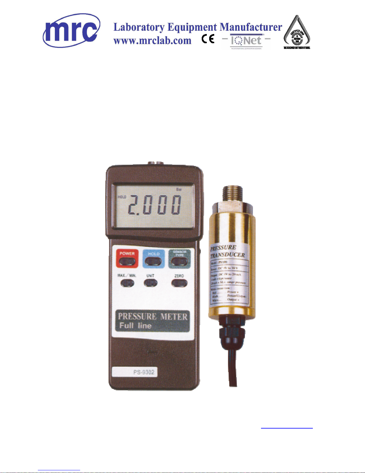
PS-9302
PRESSURE METER
Page 2

TABLE OF CONTENTS
1. FEATURES................................................................... 1
2.
T
YPICAL APPLICATION.................................................2
3. SPECIFICATIONS.........................................................2
3-1 General Specifications............................................
.
2
3-2 Electrical Specifications..........................................
.
3
4. FRONT PANEL DESCRIPTION.......................................
.
5
4-1 Display................................................................5
4-2 Power Button......................................................
.
5
4-3 Data Hold Button................................................. 5
4-4 " Max./Min. " Button............................................
.
5
4-5 Unit Button..........................................................5
4-6 Zero Button......................................................... 5
4-7 Sensor Type Button.............................................
.
5
4-8 Battery Compartment/Cover................................. 5
4-9 Sensor Input Socket.............................................5
4-10 RS-232 Output Terminal....................................... 5
4-11 Port Connector of Pressure Sensor........................
.
5
4-12 Pressure Sensor Main body................................... 5
4-13 Plug of Pressure Sensor........................................5
5. SENSOR TYPE SELECTION............................................6
6. MEASURING PROCEDURE.............................................8
7.
A
UTO POWER DISABLE................................................10
8. CALIBRATION..............................................................11
9.
RS232 PC SERIAL INTERFACE......................................
.
14
10. BATTERY REPLACEMENT............................................16
11. OPTIONAL PRESSURE SENSOR...................................16
12. OTHER OPTIONAL ACCESSORIES............................... 17
Page 3

1. FEATURES
* Meter can cooperate with 2, 5, 10, 20, 50, 100, 200, 400 Bar
sensor, new calibration procedures are not necessary when
change the new sensor .
* When change the new pressure sensor, just select
pressure type ( 2, 5, 10, 20, 50, 100, 200, 400 bar ) on the
front panel button. The sensor type will memorize into
the circuit permanently.
* 8 kind pressure units ( Bar, Psi, Kg/cm 2 mm/Hg, inch/Hg,
meter/HF2 , inch/HF2 , Atmosphere ), unit select by push
button on the front panel.
* Full line optional pressure sensors are available.
* Auto power off function, saves battery life.
* Cooperate the external pressure sensor that its output
signal is 100 mV for full scale.
* Zero button on the front panel, easy adjust the zero value
of pressure sensor.
* Available push button gain adjustment, usage for
calibration precisely if necessary.
* Separate pressure sensor, easy for remote measurement.
* Microprocessor circuit assures maximum possible accuracy,
provides special functions and features,
* Super large LCD display, easy readout.
* Records maximum & minimum readings with recall.
* Data Hold function, store the desired value on display.
* Built-in low battery indicator.
* RS 232 PC serial interface, can cooperate the personal
computer used as the Data Logger, Pressure Recorder....
& other modern pressure measuring system.
1
Page 4
2. TYPICAL APPLICATION
* Measure pneumatic pressures.
* Measure automobile engine pressures.
* Pressure for super heat measurements.
* Hydraulic servo controls.
* Refrigeration.
* Air conditioning.
* Food processing.
3. SPECIFICATIONS
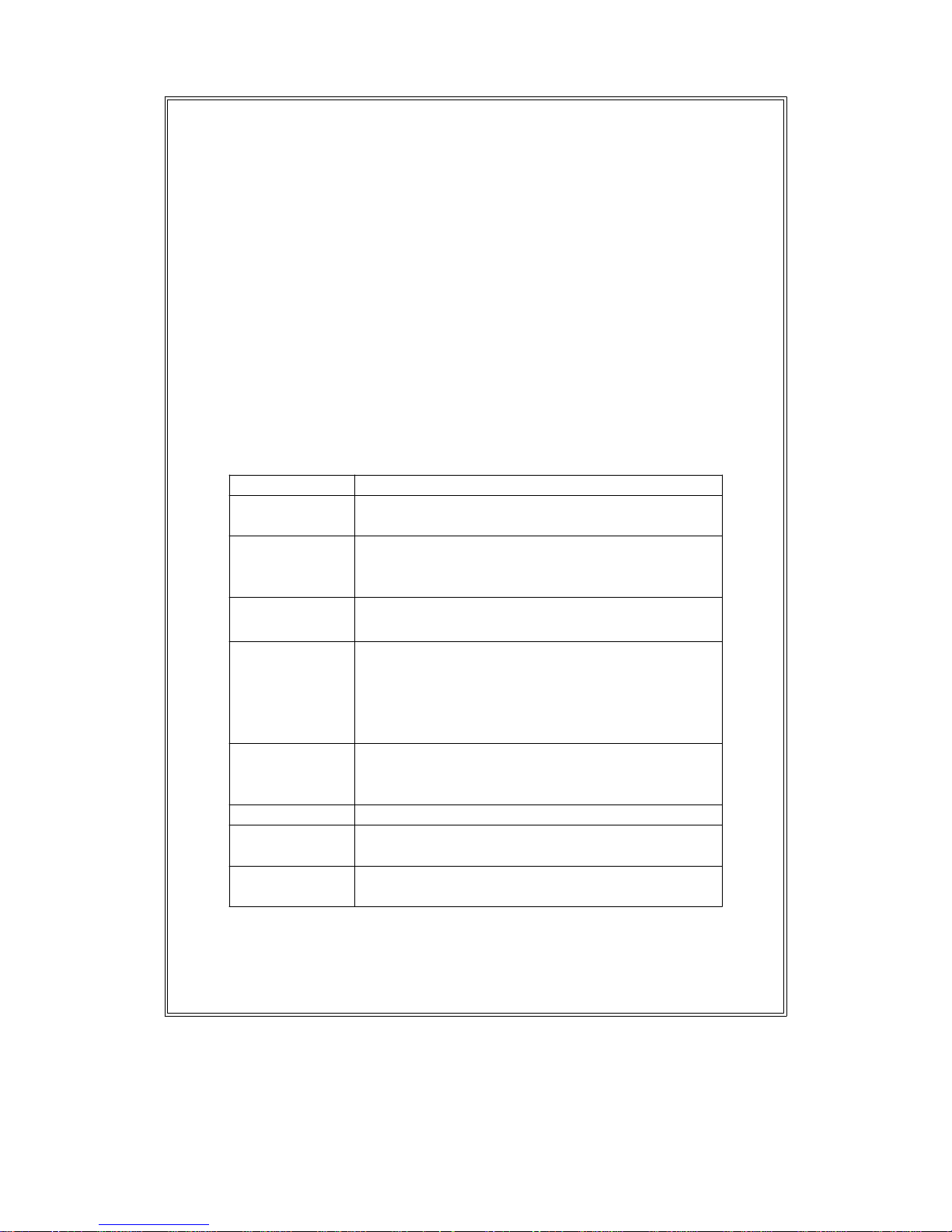
3-1 General Specifications
Circuit Microprocessor LSI circuit.
Display 61 mm x 34 mm supper large LCD display.
15 mm ( 0.6" ) di
g
it size.
Sensor type Can cooperate with optional 2, 5, 10, 20, 50,
100, 200, 400 bar sensor, new calibration are
not necessary when chan
g
e the new sensor .
Display units Bar, Psi, Kg/cm 2 mm/Hg, inch/Hg,
meter/HF2 , inch/HF2 , Atmosphere.
Accuracy ( 0.5% + 1 d )
*
Under the signal from the sensor is at full
scale ( 100 mV ).
* Meter only.
* Within 23
蚓5 蚓
Pressure Cooperate the external pressure sensor that
sensor its output si
g
nal is 100 mV for full scale.
ref. page 1
6
Zero adjust Push button on the front panel.
Span adjust Push button gain adjustment, usage for
calibration precisely if necessary.
Input signal DC 100 mV for full Scale.
from sensor
2
Page 5
Data hold By push button.
Data record Record maximum & minimum readings.
Data output RS 232 PC serial interface.
Power of
f
Auto shut off, saves battery life.
Manual off by push button.
Sampling time Approx. 0.8 second.
Operating 0 to 50 蚓( 32 to 122 蚌)
temperature
Operating Less than 80% R.H.
humidity
Power supply Alkaline or heavy duty type DC 9V battery,
006P, MN1604 (PP3) or equivalent.
Power current Approx. DC 7.0 mA.
Weight 345 g/0.76 LB
Dimension 180 x 72 x 32 mm ( 7.1 x 2.8 x 1.3 inch ).
Accessories * Instruction manual...........................1 PC
included
Optional * Pressure sensor, PS100-xxBAR,
accessories * Hard carryin
g
case ( CA-06 )
* Data acquisition software ( Windows
ref. page 16, 17
version ), SW-U801-WIN
* RS232 cable, UPCB-01
3-2 Electrical Specification
s
Sensor type 2 ba
r
5 ba
r
10 ba
r
Max. Reso- Max. Reso- Max. Resoran
g
elutionrangelution rangelution
bar 2 0.002 5 0.005 10 0.01
Psi 29 0.02 72.5 0.1 145 0.2
Kg/cm 2 2.040 0.002 5.095 0.005 10.19 0.01
mm/Hg 1500 2 3750 5 7500 10
inch/Hg 59.05 0.05 147.6 0.1 295.2 0.2
meter/HF2 20.40 0.02 50.95 0.05 101.9 0.1
inch/HF2 802 1 2006 2 4010 5
Atmosphere 1.974 0.002 4.935 0.005 9.87 0.01
3
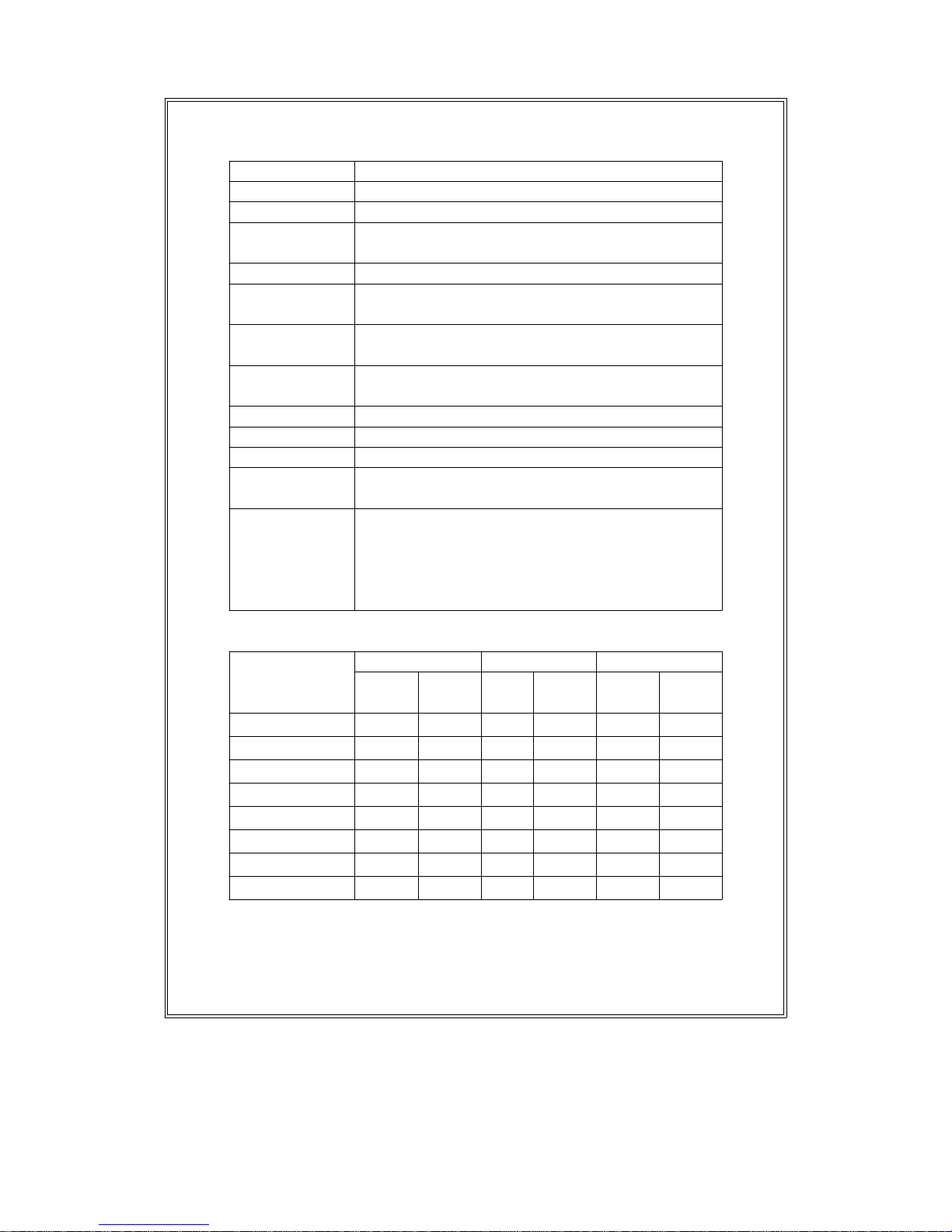
Page 6
Sensor type 20 ba
r
50 ba
r
100 ba
r
Max. Reso- Max. Reso- Max. Resoran
g
elutionrangelution rangelution
bar 20 0.02 50 0.05 100 0.1
Psi 290 0.2 725 1 1450 2
Kg/cm 2 20.40 0.02 50.95 0.05 101.9 0.1
mm/Hg 15000 20 37500 50 75000 100
inch/Hg 590.5 0.5 1476 1 2952 2
meter/HF2 204.0 0.2 509.5 0.5 1019 1
inch/HF2 8020 10 20050 20 40100 50
Atmosphere 19.74 0.02 49.35 0.05 98.7 0 .1
Sensor type 200 ba
r
400 ba
r
Max. Reso- Max. Resoran
g
elutionrangelution
bar 200 0.2 400 0.5
Psi 2900 2 5800 5
Kg/cm 2 204.0 0.2 408.0 0.5
mm/Hg 150000 200 300000 500
inch/Hg 5905 5 11810 10
meter/HF2 2040 2 4075 5
inch/HF2 80200 100 160600 200
Atmosphere 197.4 0.2 394.5 0.5
4
Page 7

4. FRONT PANEL DESCRIPTION
Fig. 1
4-1 Display 4-9 Sensor Input Socket
4-2 Power Button 4-10 RS-232 Output
4-3 Data Hold Button Terminal
4-4 " Max./Min. " Button 4-11 Port Connector of
4-5 Unit Button Pressure Sensor
4-6 Zero Button 4-12 Pressure Sensor
4-7 Sensor Type Button Main body
4-8 Battery Compartment/ 4-13 Plug of Pressure Sensor
Cover
5
Page 8

5. SENSOR TYPE SELECTION
The meter can cooperate with optional 2, 5, 10, 20, 50, 100,
200 bar sensor, new calibration are not necessary when
change the new sensor .
Those different optional pressure sensor are :
* 2 bar pressure sensor, Model : PS100-2BAR
* 5 bar pressure sensor, Model : PS100-5BAR
* 10 bar pressure sensor, Model : PS100-10BAR
* 20 bar pressure sensor, Model : PS100-20BAR
* 50 bar pressure sensor, Model : PS100-50BAR
* 100 bar pressure sensor, Model : PS100-100BAR
* 200 bar pressure sensor, Model : PS100-200BAR
* 400 bar pressure sensor, Model : PS100-400BAR
When change the different sensor ( 2 Bar, 5 Bar, 10 Bar, 20
Bar, 50 Bar...... ) should according procedures as follow :
1)
Power off the meter.
2)Use the finger to push the following 3 buttons
at the same time continuously, those buttons are :
* Data Hold Button ( 4-3 Fig. 1 )
* " Max./Min. " Button ( 4-4 Fig. 1 )
* Sensor Type Button ( 4-7 Fig. 1 )
6
Page 9

Font panel
SENSOR
HOLD TYPE
MAX./MIN.
3) Not release the above 3 keys, , push the " Power Button "
( 4-2 , Fig. 1 ) once a while. all the LCD segment will lit.
Release the 3 buttons, the display will show the memorized
sensor type.
Bar
4) Push the " Sensor Type Button " ( 4-7, Fig. 1 ) can select
the different sensor type ( 2, 5, 10, 20, 50, 100, 200, 400 Bar )
.
Until the display show the desired sensor type, push the
the " Zero button " ( 4-6, Fig. 1 ) to enter the desired
sensor type. The new setting sensor type will memorize
into the circuit even power off.
5)Power off the meter, the sensor type selecting procedures
are finished.
7
Page 10

6. MEASURING PROCEDURE
1)Plug in the " Plug of Pressure Sensor " ( 4-13, Fig. 1 ) to
meter's " Sensor Input Socket " ( 4-9, Fig. 1 )
2)Power on the meter by push the " Power Button " ( 4-2,
Fig. 1 )
3)Push the " Sensor Type Button " ( 4-7, Fig 1 ) to check if
the meter's sensor type is same as the external pressure senso
r
4)Push the " Unit Button " ( 4-5, Fig. 1 ) to select the unit (
Bar, Psi, Kg/cm 2 mm/Hg, inch/Hg, meter/HF2 ,
inch/HF2 , Atmosphere ).
5)Zero the meter by push the " Zero Button " ( 4-6, Fig. 1 ),
the display reading will change to zero value.
6) Connect the " Port Connector of Pressure Sensor "
( 4-11, Fig. 1 ) to the installation that intend to measure
the pressure value that into the sensor.
7)Apply the pressure, pressure meter will show the pressure
value.
8)Data Hold
During the measurement, pushing the " Data Hold
Button " ( 4-3, Fig. 1 ) will freeze the measured value &
display will indicate " HOLD " symbol.
* Push the "Data Hold Button" again to release the
data hold function.
9) Data Record ( Maximum, Minimum reading )
* The DATA RECORD function displays the maximum
and minimum readings. To start the DATA RECORD
function, press the " Max./Min. Button " ( 4-4, Fig. 1 )
once. " REC " symbol will appear on the LCD display.
8
Page 11

* With the " REC " symbol on the display :
(a) Push the " Max./Min. Button " ( 4-4, Fig. 1 )
once, the " Max " symbol along with the maximum
value will appear on the display.
(b) Push the " Max./Min. Button " again, the " Min "
symbol along with the minimum value will appear
on the display.
(c) To exit the memory record function, push the
" Max./Min. " button continuously at least 2 seconds.
The display will revert back to the current reading.
10 ) For quick measurement, follow the procedures
shown below :
Main procedures :
Connect the " Sensor Plug " to the meter's " Input Socket ".
Power on the meter & select the display unit.
Zero the meter by push the " Zero Button ".
Connect the pressure sensor connector to the measuring
installation
Apply the pressure, meter will display the pressure value.
Optional measuring procedures :
DATA HOLD MEMORY RECORD RS232 OUTPUT
Max., Min.
9
Page 12

Power management :
AUTO POWER OFF or MANUAL POWER OFF
(Not activated during
Memory Record Selection)
11) Measuring considerations :
*
The sensor diaphragm can be damaged by solid or
sharp objects. Never insert any object into the inlet
port.
*
The pressure sensor is compatible with industrial gases
& liquid that are compatible with the 316 stainless steel
or ceramic material. To determine the compatibility of
a liquid or gas, refer to manufacture's specification.
7. AUTO POWER DISABLE
The instrument has built-in " Auto Power Shut-off " in
order to prolong battery life. The meter will switch off
automatically if none of the buttons are pressed within 10
min.
To de-activate this feature, Select the memory
record function during measurement, by pressing
the " Max./Min. " button ( 4-4, fig. 1 ).
10
Page 13

8. CALIBRATION
Each meter already adjust & calibrate according the
condition for the 100 mV signal input to let the display
reading full scale & 0 mV input signal to let the meter
reading zero value.
Each optional pressure sensor ( PS100-XXBAR ) are
designed to meet the 100 mV output to let meter show
the full scale value & the 0 mV output signal for the
meter to read zero value.
General speaking it is not necessary to make any new
calibration procedures both of pressure meter & the
the external pressure sensor due to those two units
already done the well calibration typically.
Due to the environment temperature may drift seriously or
after a long time operation....., the meter's zero & gain
( span ) value may drift. If intend to make the measurement
precisely, it can make the new calibration as :
8-1 Zero calibration
1)Connect the meter with the pressure sensor, power on the
meter. No pressure signal into the sensor.
2)At the same time hold the following two button continuously .
" Hold Button " ( 4-3, Fig. 1 )
" Max./Min. Button " ( 4-4, Fig. 1 )
11
Page 14

The LCD will show the zero value on both up & down display.
For example :
Bar
.
0.03
3)Still hold the " Hold Button " & the " Max./Min. Button ",
at same time push the " Zero Button " ( 4-6, Fig. 1 ) once
a while, the display will flash one time & return to zero as :
Bar
.
0.00
4)Release both of the " Hold Button " & the " Max./Min.
Button ", then power off. Now the new zero value will
memorize to the circuit automatically.
8-2 Gain calibration ( Span adjust )
1)Set up the whole meter system are ready measurement,
refer the above " 6. MEASURING PROCEDURES ".
Turn on the meter and allow it to warm up for two minutes.
Should zero the meter by push the " Zero Button ".
12
Page 15

2)Connect the pressure regulator to the nitrogen bottle
and the reference gauge to the pressure regulator.
The pressure regulator should can generate the full scale
pressure value.
For example, input a standard 9.00 pressure value to the
the sensor, the display show 8.98 Bar.
3)At the same time hold the following two button continuously .
" Hold Button " ( 4-3, Fig. 1 )
" Max./Min. Button " ( 4-4, Fig. 1 )
The display show the measuring value on both up & down
display.
For example :
Bar
.
8.98
4)Still hold the " Hold Button " & the " Max./Min. Button ",
at same time.
*
Push the " Sensor Type Button " ( 4-7, Fig. 1 ) once
will add one count to the down display value.
*
Push the " Unit Button " ( 4-5, Fig. 1 ) once will decrease
one count to the down display value.
13
Page 16

Bar
.
9.00
5)Until the desired regulating value ( for example 9.00 ) be
adjusted, release both of the " Hold Button " & the
" Max./Min. Button " at same time.
Now the display flash, within 5 second should push the
" Sensor Type Button " ( 4-7, Fig. 1 ). Now the new gain
value will memorize into the circuit.
9. RS232 PC SERIAL INTERFACE
The instrument features an RS232 output via 3.5 mm
Terminal ( 4-10, Fig. 1 ).
The connector output is a 16 digit data stream which
can be utilized to the user's specific application.
An RS232 lead with the following connection will
be required to link the instrument with the PC
serial input.
Meter PC
(3.5 mm jack plug) (9W 'D" Connector)
Center Pin..................................Pin 2
Ground/shield...............................
.
Pin 5
14
Page 17

The 16 digit data stream will be displayed in the
following format :
D15 D14 D13 D12 D11 D10 D9 D8 D7 D6 D5 D4 D3 D2 D1 D0
Each digit indicate the following status :
D0 End Word
D1 & D8 Display reading, D1 = LSD, D8 = MSD
For example :
If the display reading is 1234, then D8 to D1 is :
00001234
D9 Decimal Point(DP), position from right to the left
0 = No DP, 1= 1 DP, 2 = 2 DP, 3 = 3 DP
D10 Polarity
0 = Positive 1 = Negative
D11 & D12 Annunciator for Display
Bar = 22 mm/Hg = 78 inch/HF2 = 25
Psi = 23 inch/Hg = 80 ATP = 26
Kg/cm = 77 meter/HF2 = 79
D13 1
D14 4
D15 Start Word
9600, N, 8, 1
15
Page 18

10. BATTERY REPLACEMEN
T
1)When the left corner of LCD display show "LBT",
it indicate a normal battery output of less than 6.5 V -
7.5 V. It is necessary to replace the battery. However,
in-spec measurement may still be made for several
hours after low battery indicator appears before the
instrument become inaccurate.
2)Slide the Battery Cover( 4-8, Fig. 1 ) away from the
instrument and remove the battery.
3)Install a 9 V battery ( heavy duty ) and replace the cover.
11. OPTIONAL PRESSURE SENSO
R
Description * Optional, pressure sensor that cooperate
with PS-9302.
* Out put : 100 mV DC for full scale.
* 4 pin DIN plug, 2 pins to accept DC 5 V
exciting voltage(power supply) for
pressure transducer, another two pins for
output signal of 100 mV full scale.
* Size : 30 mm dia. x 85 mm. Weight : 160 g.
Model 2 bar sensor........... PS100-2BAR
5 Bar sensor.............. PS100-5BAR
10 Bar sensor............. PS100-10BAR
20 Bar sensor............. PS100-20BAR
50 Bar sensor............. PS100-50BAR
100 Bar sensor...........
.
PS100-100BAR
400 Bar sensor...........
.
PS100-400BAR
A
ccuracy PS100-2BAR................... ( 2 % + 0.02 bar )
(
23 蚓
PS100-5BAR................... ( 2 % + 0.05 bar )
5 蚓
)
PS100-10BAR..................( 2 % + 0.1 bar )
PS100-20BAR.................
.
( 2 % + 0.2 bar )
PS100-50BAR ( 2 % + 0.5 bar )
PS100-100BAR ( 2 % + 1 bar )
PS100-400BAR ( 2 % + 4 bar )
16
Page 19

12. OTHER OPTIONAL ACCESSORIES
Carrying case Hard carrying case, CA-06.
RS-232 cable, RS-232 cable, used for connecting
Model : UPCB-01 the pressure meter & the computer.
Application After setup whole hardware
Software ( Window
version )
Pressure meter + RS-232 cable
+ Computer + software
(
SW-U801-WIN
SW-U801-WIN
)
whole system can execute as a data
lo
gg
er, data recorder.... record data
can be retrieved for EXCELL,
LOTUS-123.....
17
 Loading...