

Page 1

our purchase of this pH
METER marks a step
forward for you into the
field of precision
measurement. Although
this pH METER is a
complex and delicate
instrument, its durable
structure will allow many
years of use if proper
operating techniques are
developed. Please read
the following instructions
carefully and always keep
this manual within easy
reach.
PH METER
Model : PH-207
OPERATION MANUAL
3,
Hagavish st. Israel 58817 Tel: 972 3 5595252, Fax: 972 3 5594529
mrc@mrclab.com
MRC. 7.18
Page 2

TABLE OF CONTENTS
1. FEATURES............................................................ 1
2. SPECIFICATIONS................................................... 2
3. FRONT PANEL DESCRIPTION..................................4
4. PH CALIBRATING PROCEDURE...............................
.
5
4-1 Calibrating Consideration 5
4-2 Requirin
g
Equipment for calibration................... 5
4-3 Two Points Calibration...................................... 5
4-4 Sin
g
le Point Calibration..................................... 6
5. PH TEMPERATURE COMPENSATION........................6
5-1 Manual temperature compensation.................... 7
5-2 Automatic temperature compensation................7
6. MEASURING PROCEDURE.......................................7
6-1 PH Measurement..............................................7
6-2 mV Measurement............................................. 8
6-3 Temp. Measurement.........................................8
7. CIRCUIT ADJUSTING PROCEDURES WHEN
CHANGING THE TEMP. PROBE...............................
.
11
8. MEASURING CONSIDERATION............................... 12
9. RS232 PC SERIAL INTERFACE.................................12
10. BATTERY REPLACEMENT........................................ 14
11. OPTIONAL ACCESSORIES.......................................
.
14
Page 3

1. FEATURES
* Microprocessor circuit assures high accuracy and provides
special functions and features.
* Super large LCD display with contrast adjustment for best
viewing angle.
* Dual function meter's display.
* Heavy duty & compact housing case.
* Records Maximum, Minimum and Average readings with
RECALL.
* Data hold.
* Auto shut off saves battery life.
* Operates from OO6P DC 9V battery.
* RS 232 PC serial interface.
* Used the durable, long-lasting components, including a
strong, light weight ABS-plastic housing case.
* Multi-measurement : PH, mV, Temperature.
* Temperature function for 蚓 or 蚌 be selected by push
button on front panel easily.
* Show the PH & temperature values on the same LCD
display at the same time.
* High input impedance avoid measuring error.
* Wide manual temperature compensation range from
0 蚓 to 100 蚓, high accuracy.
* Auto temperature compensation range via. the external
optional temp. probe.
* The values of "Manual temp. compensation" are reading
from the LCD display directly, no errors & easy operation .
* With the optional temp. probe for automatic temp.
compensation of PH function or temp. measurement.
* The instrument build in mV(milli volt) measuring
function, letting you make ion-selective, ORP, and other
precise mV measurement.
1
Page 4
* Wide applications: water conditioning, aquariums, beverage,
fish hatcheries, food processing, photography, laboratory,
paper industry, plating industry, quality control, school &
college, water conditioning.
2. SPEC
IFICATION
S
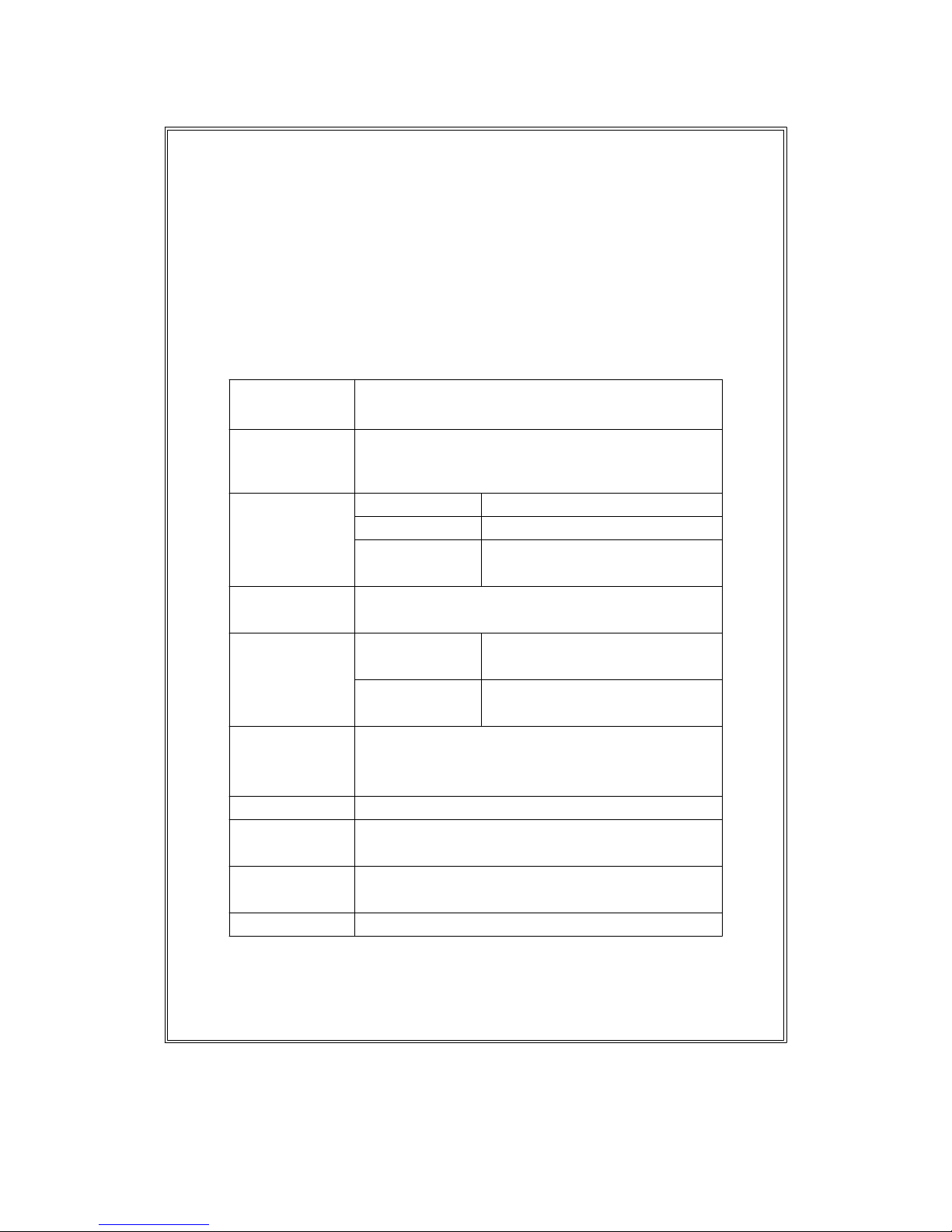
2-1 General Specifications
Circuit Custom one-chip of microprocessor LSI
circuit.
Display Dual function meter's display, 13 mm(0.5")
Super lar
g
e LCD display with contrast
adjustment for best viewing angle.
Measurement PH 0 to 14 PH
mV 0 to 1999 mV
Temperature 0 to 65 蚓
32 to 150 蚌
Input 10 12ohms.
Impedance
Temperature Manual 0 to 100 蚓, adjusting by
Compensation push button on front panel.
For Automatic With the optional TEMP.
PH Range probe, 0 to 65 蚓.
Calibration Built in SLOPE(PH 4) & CAL.(PH 7)
For calibration VR ( multi-turns potentiometers )
PH Range on front panel, high reliability.
Data hold To hold the reading values on display.
Memory Records Maximum, Minimum and Average
Recall readings with RECALL.
Power off Auto shut off saves battery life, or manual
off by push button.
Data Output RS 232 PC serial interface.
2
Page 5
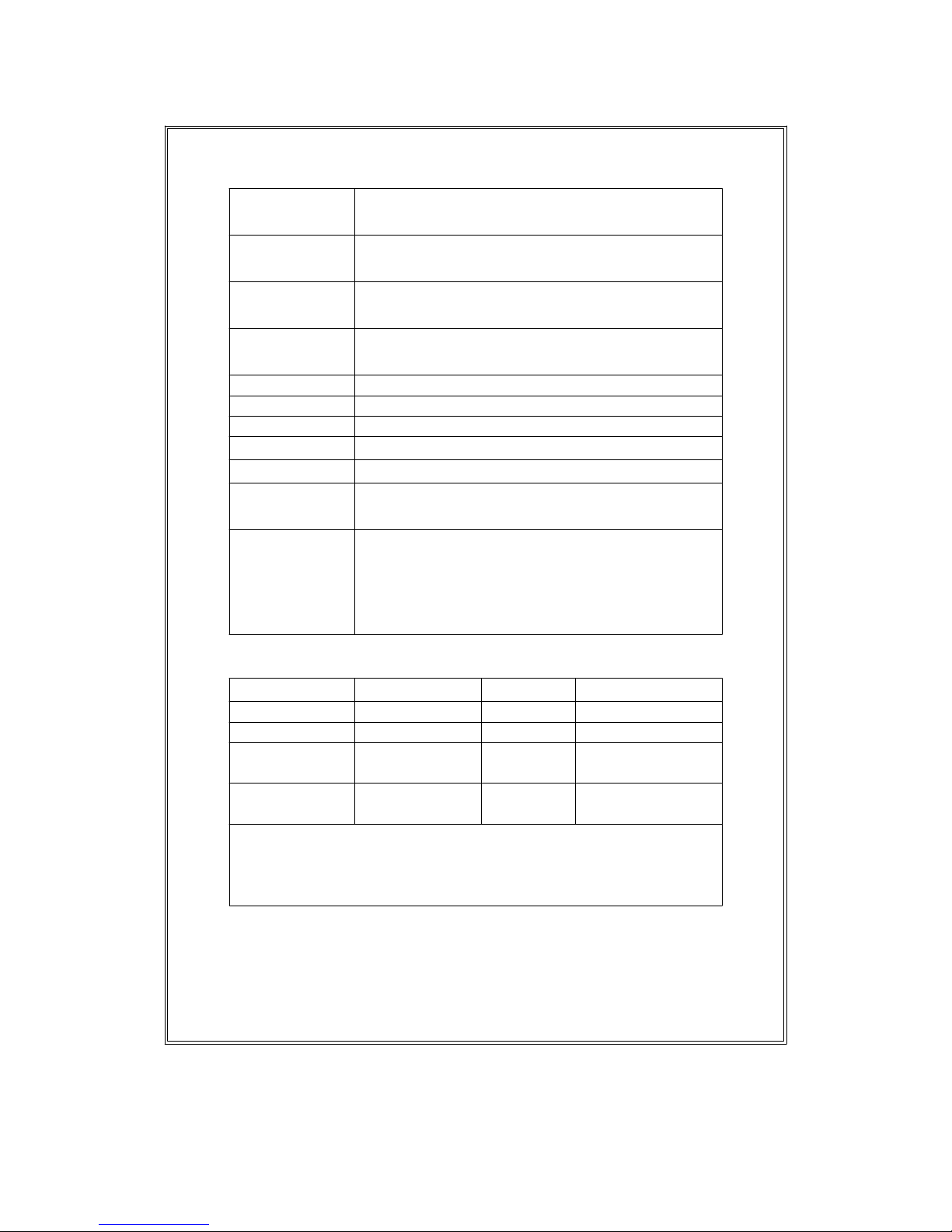
Over input Indication of "- - - -".
indication
PH Any combination PH electrode with
Electrode BNC connector/
Operating 0 蚓 to 50 蚓(32 蚌 to 122 蚌).
Temperature
Operating Max. 80% RH.
Humidity
Sampling Time Approx. 0.8 second.
Power Supply 006P DC 9V battery(Heavy duty type).
Power Current Approx. DC 5.7 mA.
Weight 270 g/0.59 LB (included batteries)
Size ( meter ) 180 x 72 x 32 mm(7.1 x 2.8 x1.3 inch).
Standard Instruction manual...........1 PC.
Accessories
Optional Carrying case
Accessories pH electrode, PE-01, PE-11, PE-03.
ATC temp. probe, TP-07.
PH 4 buffer solution, PH-04.
PH 7 buffer solution, PH-07.
2-2 Electrical Specifications (23 5 蚓)
Measurement Range Resolution Accuracy
PH 0 to 14 PH 0.01 PH 0.03 PH + 2 d)
mV 0 to 1999 mV 1 mV (0.5% + 1 d)
Temp.(蚓) 0 to 65
蚓
0.1
蚓1蚓
( 0 - 50蚓 )
4
蚓
( > 50蚓 )
Temp.(蚌) 32 to 150
蚌
0.1
蚌
.8
蚌
(32 - 122蚌)
.2
蚌
( > 122蚌 )
*
PH accuracy are based on after calibration, meter only.
*
Spec. tested under the environment RF Field Strength les
s
than 3 V/M & frequency less than the 30 MHz only.
3
Page 6

3. FRONT PANEL DESCRIPTION
Fig. 1
3-1 Display 3-10 Manual Temp. Button
3-2 Power Off/On button 3-11 Function Select Switch
3-3 Data Hold Button 3-12 SLOP(PH 4) Calibration
3-4 蚓/ 蚌 button VR
3-5 LCD Contrast Adjust 3-13 >> Button
VR (Manual Temp. adjust)
3-6 Memory "Record" 3-14 Battery Compartment/
Button Cover
3-7 Memory "Call" Button 3-15 Input Socket
3-8 > Button (BNC, for PH & mV)
(Manual Temp. ad
j
ust) 3-16 RS-232 Out Terminal
3-9 CAL.(PH 7) Calibration 3-17 Temp. Probe Input Socket
VR
4
Page 7

4. PH CALIBRATING PROCEDURE
4-1 Calibrating Consideration
The PH meter already calibrated by mV signal
that simulated from the mV output of the ideal PH
ELECTRODE (base on 25 environment). For an
ideal electrode will produce 0 mV at PH 7.00, but
most electrodes are slight off.
It is necessary to make the following calibration
procedures (4-2, 4-3), if the user intend to keep
instrument along the electrode within high accuracy or the
first time use the meter & the electrode.
4-2 Requiring Equipment for Calibration
1)Combination PH ELECTRODE(optional).
2)Two buffer solutions (optional) : PH-07 & PH-04.
4-3 Two Points Calibration
1
)
Power on the instrument using the " Power On/Off
Button " (3-2, Fig.1).
2)
Select the " Function Switch " (3-11, Fig.1) to the
" PH MANUAL TEMP. " position.
3)Adjust the " Temperature Compensation Values " to
be same as the temperature values of the PH-04
buffer solution.
The adjusting procedures, please refer to 5-1.
4)Connect the combination PH ELECTRODE to the
" BNC socket " (3-15, Fig. 1) and place the electrode
into the buffer solution PH-07.
Use the screw to adjust the " PH 7 calibration VR " (3-9,
Fig.1) until the display reading reach to 7.00 0.01.
5
Page 8

5)Rinse the electrode in the distilled water.
Place the electrode into the PH-04 ( or PH-10 ) buffer
solution. Use the screw to adjust the " PH 4 calibration
VR " (3-12, Fig.1) until the display reading reach to
4.00 0.01 ( or 10.00 0.01 for PH-10 ).
6)Rinse the electrode in the distilled water again.
7)Repeat above (4) to (5) procedures two times at least.
8)The instrument and electrode are now finished the
" TWO POINTS CALIBRATION " & ready for the
measurement.
4-4 Single Point Calibration
1)Power on the instrument by pushing the " Power On/Off
Button " (3-2, Fig.1).
2)
Select the " Function Switch " (3-11, Fig.1) to the
" PH MANUAL TEMP. " position.
3)Connect the combination PH ELECTRODE to the "
BNC socket " (3-15, Fig. 1) and place the electrode into
the PH-07 buffer solution.
Use the screw to adjust the " PH 7 calibration VR " (3-9,
Fig.1) until the display reading reach to 7.00 0.01.
4)Repeat above (3) procedures two times at least.
5)
The instrument and electrode are now finished the
" SINGLE POINTS CALIBRATION " & ready for the
measurement.
5. PH TEMPERATURE COMPENSATION
Enables the meter to read solutions at various temperatures. The meter corrects for an electrode's temperature
dependency. The compensation may be manual with a
button adjustment on the meter, or it may be automatic
with a optional temperature sensing probe immersed in
the test solution.
6
Page 9

5-1 Manual temperature compensation
1)Select the " Function Switch " (3-11, Fig.1) to the " PH
MANUAL. TEMP. " position.
2)Push the " MANUAL Temp. Button " (3-10, Fig.1) first,
then the display will show " 25.0 蚓 " for the initial manual
setting temp.
3)Push the " > Button " (3-8, Fig. 1) once will up 0.1 蚓 to
the manual setting temperature.
4)Push the " >> Button " (3-13, Fig.1) once will up 1 蚓 to
the manual setting temperature.
Push the " >> Button " continuously will up 1 蚓 to
setting temperature for every half seconds.
5-2 Automatic temperature compensation
1)Select the " Function Switch " (3-11, Fig.1) to the " PH
AUTO TEMP. " position.
2)Plug in the " Optional Temp. Probe, TP-07 " into the "
Temp. Socket " (3-17, Fig. 1).
3)Place the "Temp. Probe" into the tested solution, then
the PH function will be temperature compensated
automatically.
6. MEASURING PROCEDURE
6-1 PH Measurement
After the instrument and PH electrode are calibrated, then
the unit is now ready for measuring.
1)Connect the combination PH ELECTRODE to the " BNC
socket " (3-15, Fig. 1).
2)
Power on the instrument by pushing the " Power
On/Off Button " (3-2, Fig.1).
3)If the operating is under the " Manual temperature
compensation ", then please according the above 5-1
measuring procedures.
7
Page 10

If the operating is under the " Automatic temperature
compensation ", then please according the above 5-2
measuring procedures.
4)Place the electrode into the measured solution, then the
instrument will display the PH value.
5)After make the measurement, please rinse the electrode
in distilled water.
6-2 mV Measurement
The instrument build in mV(milli volt) measuring
function, letting you make ion-selective, ORP
(oxidation-reduction potential), and other precise mV
measurements.
Select the "Function Switch"(3-11, Fig.1) to the "mV"
position. Then the meter will show the mV values on the
display.
6-3 Temp. Measurement
1)Select the "Function Switch"(3-11, Fig.1) to the
" PH AUTO TEMP. " position.
2)Plug in the " Optional Temp. Probe " into the " Temp. Input
Socket " (3-17, Fig. 1).
3) * If intend to measure the " ", then push the "
button " to select the " " unit.
* If intend to measure the " ", then push the "
button " to select the " " unit.
4)Place the "Temp. Probe" into the tested solution, then
the meter will show the temperature value.
8
Page 11

Consideration :
When use the Temp. Probe, As to keep the temp. reading
be stable, should plug in the PH electrode into the meter
at the same time. If only plug in the temp. probe, then
the temperature reading value may exist little deviation.
6-4 Data Hold
1)During the measurement, Push the " Hold
Button " (3-3, Fig. 1) will hold the display values &
LCD will show the " D.H. " marker.
2)Push the "Data Hold Button" again will release the
data hold function.
6-5 Data Record( Max., Min., Average reading)
1)The DATA RECORD function displays the maximum,
minimum and average readings. To start the DATA
RECORD function, press the " Record Button " (3-6,
Fig. 1) once. " REC " symbol will appear on the LCD
display.
2)With the " REC " marker on the display.
(a) Push the " CALL Button " (3-7, Fig. 1) once,
then the " Max " symbol along the maximum value
will appear on the LCD display.
(b) Push the " CALL Button " once, then the " Min "
symbol along the minimum value will appear on
the LCD display.
(c) Push the " CALL Button " once, then the " AVG "
symbol along the average value will appear on
the LCD display.
(d) To exit memory record function, push the " RECORD
Button " once again. The display will revert back
to current reading.
After stop the "Record" function, the symbol
of " REC ", " Max ", " Min ", " AVG " will disappear.
9
Page 12

6-6 Following are the block diagrams for quick
measuring procedures
Calibration
Set the Single point calibration
Power manual PH 7(CAL.)
ON temp.
values Two points calibration
PH 7(CAL.) & PH4(SLOPE)
PH measuring procedures
Setting the Manual temp. M
compensation values E
on front panel A
Power S
ON or U
R
E
Automatic temperature M
temperature compensation E
by optional ATC probe N
T
Optional measuring procedures
DATA HOLD MEMORY RECORD RS232 OUTPUT
Max., Min. AVG
10
Page 13

Power management
AUTO POWER OFF or MANUAL POWER OFF
(Not activated during
Memory Record Selection)
7. CIRCUIT ADJUSTING PROCEDURES
WHEN CHANGING THE TEMP. PROBE
1)The instrument can connect the optional Temperature
Probe be used as a THERMOMETER & making the
automatic temperature compensation for PH function.
2)When change a new TEMP. PROBE, it need to make
following calibrating procedure:
Plug in the optional Temperature Probe (TP-07)
into the " Temp. Input Socket " (3-17, Fig.1). Slide
the " Function Switch " (3-11, Fig. 1) to the " PH
EXT. TEMP. " position, place probe in water with a
mercury thermometer, adjust to the correct
temperature with the " VR 6 " ( The VR6 is installed
into the battery compartment, Fig. 2)
Front Panel
Fig. 2
Battery Compartment
Case Bottom VR7 VR6
Remark : VR 6 is for temperature gain adjustment VR.
VR 7 is for temperature zero adjustment VR.
11
Page 14

8. MEASURING CONSIDERATION
1)The meter is built the " Auto power shut off " to save
battery life. If not any function button be pushed within
approx. 10 minutes, then the power will be off automatically.
If the user is not intend to execute the " Auto Power
off " function, then should take the following
procedures :
During the measurement, push the " Record Button "
(3-6, Fig. 1) to execute the memory record
function.
(2) It may necessary to change the display contrast by adjust
"LCD Contrast adjust VR"(3-5, Fig.1) due to user
alter the view angle or battery power voltage drift.
9. RS232 PC SERIAL INTERFACE
The instrument features an RS232 output via 3.5 mm
Terminal (3-16, Fig. 1).
The connector output is a 16 digit data stream which
can be utilized to the user's specific application.
An RS232 lead with the following connection will
be required to link the instrument with the PC
serial input.
Meter PC
(3.5 mm jack plug) (9W 'D" Connector)
Center Pin...................................Pin 2
Ground/shield..........................
.
Pin 5
12
Page 15

The 16 digit data stream will be displayed in the
following format :
D15 D14 D13 D12 D11 D10 D9 D8 D7 D6 D5 D4 D3 D2 D1 D0
Each digit indicate the following status :
D0 End Word
D1 to D4 Upper Display reading, D1=LSD, D4=MSD
D5 to D8 Lower Display reading, D5=LSD, D8=MSD
D9 Decimal Point(DP) for Upper display.
0 = No DP, 1= 1 DP, 2 = 2 DP, 3 = 3 DP
D10 Decimal Point (DP) for lower display
0 = No DP, 1= 1 DP, 2 = 2 DP, 3 = 3 DP
D11 & D12 Anunuciator for Upper Display
00 =No Symbol 07 = mg/L 14 =mS
01 =C 08 = m/s 15 =Lux
02 =F 09 = Knots 16 =Ft-cd
03 = % 10 = Km/h 17 =dB
04 = % RH 11 = Ft/min 18 =mV
05 = % PH 12 = mile/h
06 = % O 2 13 = uS
D13 Anunuciator for Lower Display
0 =No Symbol 1 =C 2 =F
D14 Reading Polarity for the Display
0 = Both upper & lower display value are "+".
1 = Upper "-", Lower "+".
2 = Upper "+", Lower "-".
3 = Both upper & lower display value are "-".
D15 Start Word
13
Page 16

10. BATTERY REPLACEMENT
1)When the left corner of LCD display show " LBT ", it
is necessary to replace the battery. However, in-spec.
measurement may still be made for several hours after
low battery indicator appears before the instrument
become inaccurate.
2)Slide the " Battery Cover " (3-14, Fig. 1) away from the
instrument and remove the battery.
3)Replace with 9V battery (heavy duty type) and reinstate
the cover.
4)Make sure the battery cover is secured after change the
battery.
11. OPTIONAL ACCESSORIES
CARRYING CASE Hard carrying case
CA-06
CARRYING CASE Soft carrying case with sash.
CA-05A
PH ELECTRODE General purpose, laboratory &
PE-03 field usage. 12 mm dia. x 120 m.
Epoxy body, 1 - 13 pH.
PH ELECTRODE General purpose, laboratory &
PE-11 field usage. 9.5 mm dia. x 120 m.
Epoxy body, 1 - 13 pH.
(0 - 14 pH typical)
BUFFER SOLUTION PH 7.00 standard buffer solution.
PH-07
BUFFER SOLUTION PH 4.00 standard buffer solution.
PH-04
ATC TEMP. PROBE ATC ( automatical temperature
TP-07 control ) temperature probe.
14
 Loading...