

Page 1
SD card real time Data Recorder
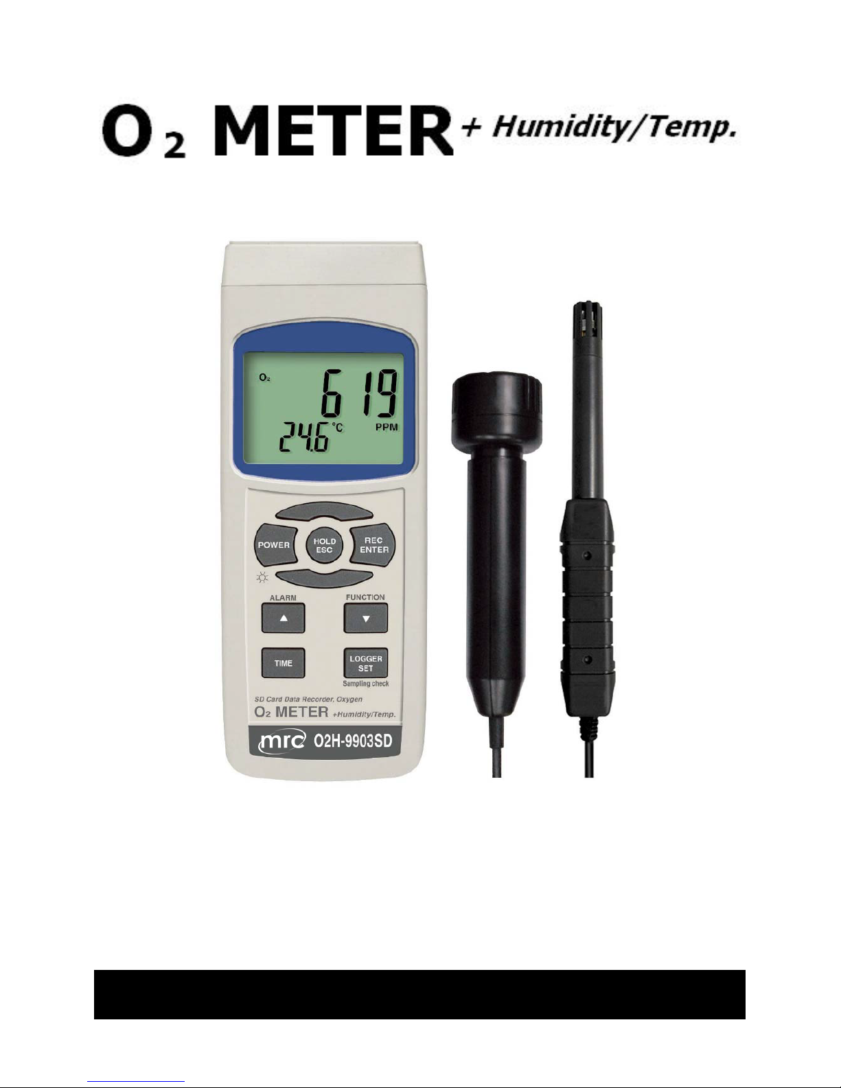
O2, Humidity, Dew point, Temp.
Model : O2H-9903SD
Your purchase of this O2 + HumidityTemp. meter with SD
CARD DATA RECORDER marks a step forward for you into the
field of precision measurement. Although this METER is a
complex and delicate instrument, its durable structure
developed. Please read the following instructions carefully and
always keep this manual within easy reach.
OPERATION MANUAL
Page 2

TABLE OF CONTENTS
1. FEATURES..................................................................1
2. SPECIFICATIONS........................................................2
2-1 General Specifications...........................................
.
2
2-2 Electrical Specifications......................................... 5
3. FRONT PANEL DESCRIPTION......................................
.
8
4 MEASURING PROCEDURE............................................10
5. OTHER FUNCTION......................................................11
5-1 Data Hold.............................................................11
5-2 Record ( Max./ Min. reading )................................
.
11
5-3 LCD Backlight ON/OFF...........................................12
6. DATALOGGER............................................................
.
13
6-1 Preparation before execute datalogger function....................13
6-2 Auto Datalogger ( Set sampling time 1 second )..............≧ 14
6-3 Manual Datalogger ( Set sampling time = 0 second )...........
.
15
6-4 Check time information.......................................................
.
15
6-5 Check sampling time information.........................................
.
16
6-6 SD Card Data structure.......................................................
.
16
7. Saving data from the SD card to the computer.............
.
18
8. ADVANCED SETTING..................................................
.
20
9. POWER SUPPLY from DC ADAPTER..............................26
10. BATTERY REPLACEMENT...........................................26
11. SYSTEM RESET.........................................................27
12. RS232 PC SERIAL INTERFACE...................................
.
27
13. PATENT...................................................................
.
29
Page 3

1. FEATURES
* Real time recorder, save the data into the SD memory
card and can be down load to the Excel, extra software
is no need. User can make the further data or graphic
analysis by themselves. under the Excel software.
* At the same time, the SD memory card can record 3
probe's data ( %RH/CO2/O2/Temp. or
%RH/CO2/CO/Temp. ) along with the time information
into the one Excel file at the same time.
* Manual datalogger is available, during execute the
manual datalogger function, it can set the different
location no. ( position 1 to position 99 ).
* Air quality measurement application, multi-function :
CO2 (Carbon dioxide ), CO ( Carbon monoxide ), O2
( Oxygen in air ), Humidity, temperature measurement.
* O2 range : 0 to 30.0 % x 0.1 %.
* CO2 range : 0 to 6,000 ppm x 1 ppm., optional probe.
* CO range : 0 to 1,000 ppm x 1 ppm, optional pribe
* Humidity range: 10 to 95 %RH.
* Dew point Temp. and Wet bulb Temp. measurement.
* Temp. range : 0 to 50.0 , / .℃℃℉
* CO2 sensor : NDIR, long term reliability.
* CO, O2 sensor : Galvanic cell type.
* Humidity sensor : Precision capacitance sensor
* Alarm setting with the beeper sound output.
* Sampling time for data recorder is 2 seconds to 8 hours.
* Complete set with 2 probes :
O2/Temp. probe, Humidity/Temp. probe.
* CO2/Temp. probe, CO/Temp. probe is optional.
* Separate probe, easy for remote measurement.
* Meter can cooperate with 2 GB to 16 GB SD card, SD
card is optional.
* RS232/USB computer interface.
*Patented.
1
Page 4
2. SPECIFICATIONS
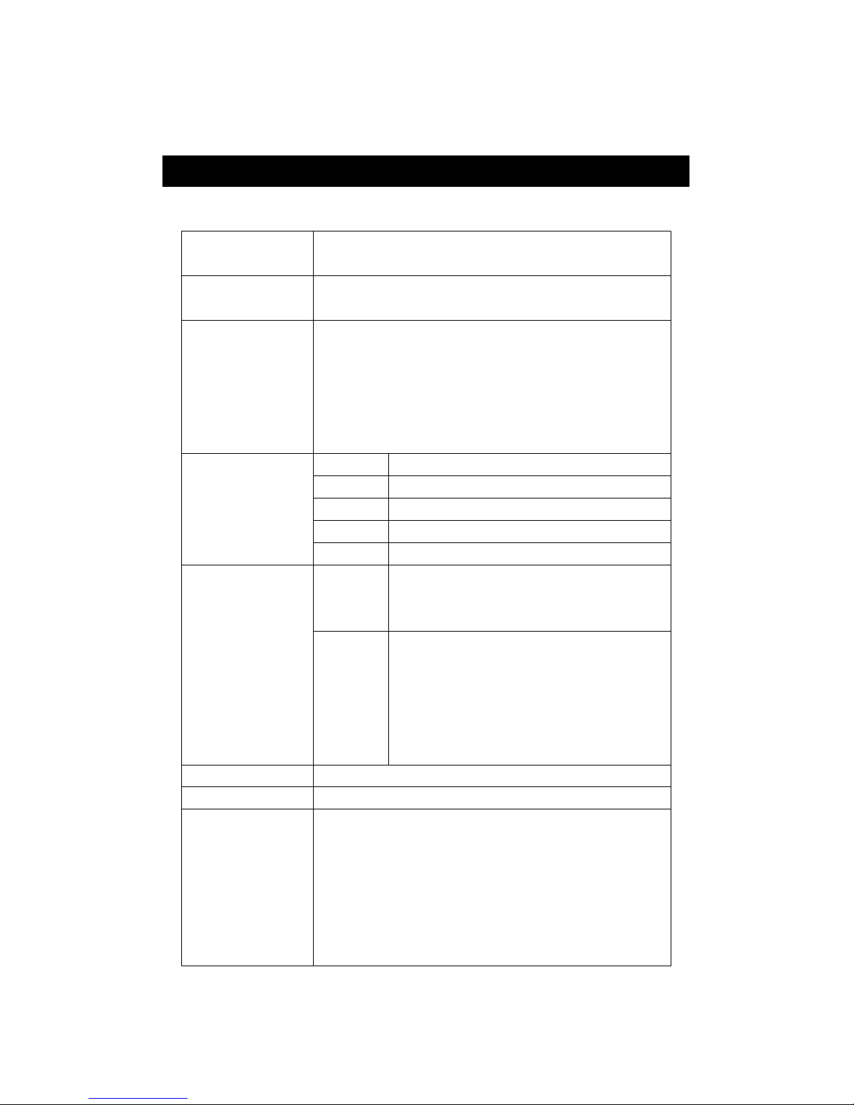
2-1 General Specifications
Circuit Custom one-chip of microprocessor LSI
circuit.
Display LCD size : 52 mm x 38 mm
LCD with green backlight ( ON/OFF ).
Measurement O2 ( Oxygen in air )
CO2 (Carbon dioxide ), optional probe
CO ( Carbon monoxide ), optional probe
Humidity
Dew point Temp., Wet bulb Temp.
Temperature
Sensor CO2 NDIR * Nondispersive infrared sensor
structure Humidity Precision capacitance sensor
O2 Galvanic cell type
CO Galvanic cell type
Temp. Precision thermistor
Datalogger Auto 2 sec to 8 hour 59 min. 59 sec.
Sampling Time
@ Sampling time can set to 1 second,
Setting range
but memory data may loss.
Manual Push the data logger button
once will save data one time.
@ Set the sampling time to
0 second.
@ Manual mode, can also select the
1 to 99 position ( Location ) no.
Data error no. 0.1% of total saved data max.
Memory Card SD memory card. 1 GB to 16 GB.
A
dvanced * SD memory card Format
setting * Set clock time
* Set sampling time
@ main setting
* Auto power OFF management
* Set beep Sound ON/OFF
* Decimal point of SD card setting
* Temp. unit setting
* Alarm value setting
2
Page 5
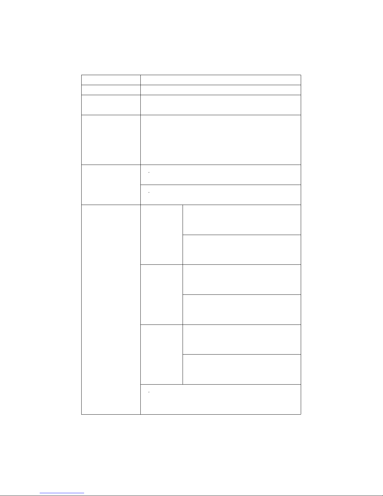
Data Hold Freeze the display reading.
Memory Recall Maximum & Minimum value.
Sampling Time Approx. 1 second.
of Display
Data Output RS 232/USB PC computer interface.
* Connect the optional RS232 cable
UPCB-02 will get the RS232 plug.
* Connect the optional USB cable
USB-01 will get the USB plug.
Power Supply
*
A
Alkaline or heavy duty DC 1.5 V battery
( UM3, AA ) x 6 PCs, or equivalent.
*
A
DC 9V adapter input. ( AC/DC power
adapter is optional ).
Power Current CO2 Normal operation ( w/o SD card save
measure- data and LCD Backlight is OFF) :
ment
Approx. DC 136.5 mA.
When SD card save the data and LCD
Backlight is OFF) :
Approx. DC 166 mA.
Humidity Normal operation ( w/o SD card save
measure- data and LCD Backlight is OFF) :
ment
Approx. DC 10.5 mA.
When SD card save the data and LCD
Backlight is OFF) :
Approx. DC 40 mA.
O2 or Normal operation ( w/o SD card save
CO data and LCD Backlight is OFF) :
measure-
Approx. DC 12.5 mA.
ment When SD card save the data and LCD
Backlight is OFF) :
Approx. DC 42.5 mA.
* AIf LCD backlight on, the power
consumption will increase approx.
12 mA.
3
Page 6
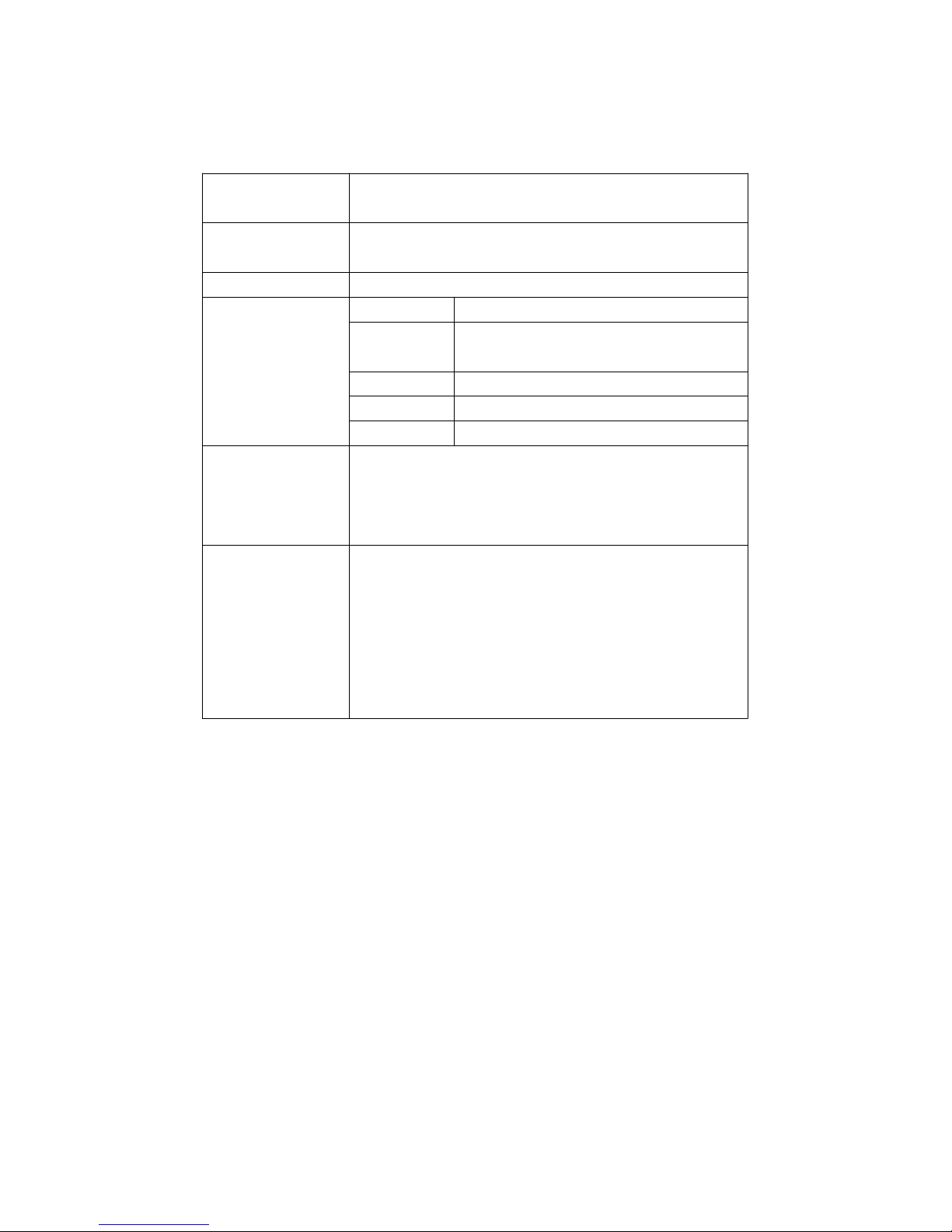
Operating 0 to 50 . ( 32 to 122 ).℃℉
Temperature
Operating Less than 80% R.H.
Humidity
Weight 350 g/0.77 LB.
Dimension Meter 177 x 68 x 45 mm
Humidity 197 mm in length.
probe
CO2 probe 190 x 38 x 28 mm
O2 probe 150 x 38 x 38 mm
CO probe 150 x 38 x 38 mm
Accessories Instruction manual...........................1 PC
Included Hard carrying case, CA-08................1 PC
O2 probe........................................
.
1 PC
Humidity probe................................1 PC
Optional CO2 probe
Accessories CO probe
SD memory card ( 2 GB )
AC to DC 9V adapter.
USB cable, USB-01.
RS232 cable, UPCB-02.
Data Acquisition software, SW-U801-WIN.
4
Page 7
2-2 Electrical Specifications (23±5 )℃
O2 ( Air oxygen )
Range 0 to 30 %O2.
O2 Resolution 0.1 %O2.
* Air oxygen
Accuracy ± ( 1 % reading + 0.2 % O2 ).
@ After calibration
Response time 15 secon
d
≦
@ t 90
Overload 100 %O2.
protection
Environment 0.9 to 1.1 atmosphere.
pressure range
Expected life 2 years.≧
time
Alarm If the measurement Air oxygen
value < 18.0 %O2, the buzzer
will sound for warning.
Temperature Range 0 to 50 ,32 to 122 .℃℃℉ ℉
Resolution 0.1 degree
Accuracy : ± 0.8 ℃℃ : ± 1.5 .℉℉
Humidity/Temperature
Range 5 % to 95 % R.H.
Humidity Resolution 0.1 % R.H.
Accuracy 70% RH :≧
± (3% reading + 1% RH).
< 70% RH :
±3% RH.
Range 0 to 50 ,32 to 122 .℃℃℉ ℉
Temperature Resolution 0.1 degree
Accuracy ℃ ±0.8 .℃
℉ ±1.5 .℉
5
Page 8
Dew Point Temp. ( Humidity )
℃ Range -25.3 to 48.9 ℃℃
Resolution 0.1 ℃
℉ Range -13.5 to 120.1 .℉℉
Resolution 0.1 .℉
Remark :
* Dew Point display value is calculated from the
Humidity/Temp. measurement automatically.
* The Dew Point accuracy is sum accuracy value of Humidity
& Temperature measurement..
Wet bulb Temp. ( Humidity )
℃ Range -21.6 to 50.0 ℃℃
Resolution 0.1 ℃
℉ Range -6.9 to 122.0 .℉℉
Resolution 0.1 .℉
Remark :
* Wet bulb display value is calculated from the Humidity/Temp.
measurement automatically.
* The Welt bulb accuracy is sum accuracy value of Humidity
& Temperature measurement..
6
Page 9
CO2 ( Carbon dioxide ), optional probe
Range 0 to 6,000 ppm
CO2 Resolution 1 ppm
( Carbon
A
ccuracy ± 40 ppm
dioxide )
* 1,000 ppm.≦
± 5% of reading
23 ± 5 .℃
* > 1,000 ppm 3,000 ppm.≦
± 250 ppm typically
* > 3,000 ppm.
Repeatability ± 20 ppm
* 3,000 ppm.≦
T
emperature Range 0 to 50 ,32 to 122 .℃℃℉ ℉
Resolution 0.1 degree
A
ccuracy : ± 0.8 ℃℃ : ± 1.5 .℉℉
CO ( Carbon dioxide ), optional probe
Range 0 to 1,000 ppm
CO Resolution 1 ppm
* Carbon
Accuracy ± ( 5% + 2 ppm )
monoxide
Response < 30 seconds
time *
Repeatability < 2%
Zero drift in < 5 ppm
long term
Sensitivity < 5% per year
drift
* The response time value is specified to reach
the 90% reading value.
Temperature Range 0 to 50 ,32 to 122 .℃℃℉ ℉
Resolution 0.1 degree
Accuracy : ± 0.8 ℃℃ : ± 1.5 .℉℉
@ Above specification tests under the environment RF Field Strength less than 3
V/M & frequency less than 30 MHz only.
7
Page 10
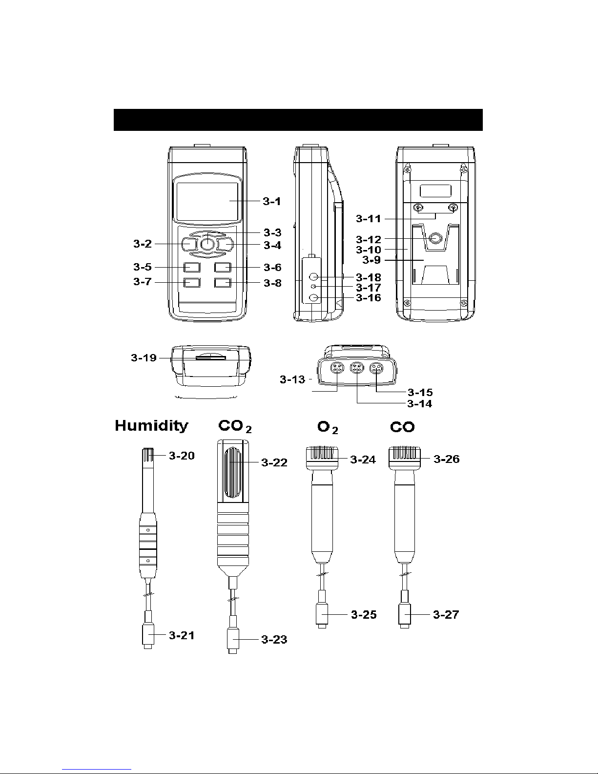
3. FRONT PANEL DESCRIPTION
Fig. 1
8
Page 11

3-1 Display
3-2 Power Button ( Backlight Button )
3-3 Hold Button ( ESC Button )
3-4 REC Button ( Enter Button )
3-5 Alarm Button ( Button )▲
3-6 Function Button ( Button )▼
3-7 Time Button
3-8 Logger Button ( SET Button, Sampling check )
3-9 Stand
3-10 Battery Compartment/Cover
3-11 Battery Cover Screw
3-12 Tripod Fix Nut
3-13 Humidity Probe Input Socket
3-14 CO2 Probe Input Socket
3-15 O2/CO Probe Input Socket
3-16 DC 9V Power Adapter Input Socket
3-17 Reset Button
3-18 RS-232 Output Terminal
3-19 SD Card Socket
3-20 Humidity Sensing Head
3-21 Humidity Probe Plug
3-22 CO2 Sensing Head
3-23 CO2 Probe Plug
3-24 O2 Sensing Head
3-25 O2 Probe Plug
3-26 CO Sensing Head
3-27 CO Probe Plug
9
Page 12

4. MEASURING PROCEDURES
Measuring consideration
a.The meter can plug in the max. 3 probes at the same time.
The thress prones are :
Humidity probe, CO2 probe, O2 probe.
or
Humidity probe, CO2 probe, CO probe.
b.Though the meter can plug the above 3 probes, but the
meter Display only can show the one probe
measurement value at the same time.
c. If the meter already plug the above 3 probes,
when make the SD card to record the data, it
can save the 3 probes' measurement value
along the time information at the same time.
Measuring procedures
1)Plug in the " Plug of probe " ( 3-21, 3-23, 3-25, 3-27
Fig. 1 ) to meter's " Probe Input Socket " ( 3-13, 3-14,
3-15 Fig. 1 )
*
O2 probe and Humidity probe are the standard
accessories ( probes are included
)
*
CO2 probe , CO probe is the optional probe.
10
Page 13

2)Power on the meter by pushing the " Power Button "
( 3-2, Fig. 1 ) once.
3)Press the " Function Button " ( 3-6, Fig. 1 ) once in
sequence to select the measuring function :
Display Function
text
rH Humidity/Temp.
dP Dew point Temp.
_ET Wet bulb Temp.
CO CO/Temp.
O2 O2/Temp.
CO2 CO2/Temp.
Remark :
A
fter select the desired function, power off the meter
then power on again, the meter circuit memory wil
l
save the selected unit with default.
5. OTHER FUNCTION
5-1 Data Hold
During the measurement, press the " Hold Button " ( 3-3,
Fig. 1 ) once will hold the measured value & the LCD will
display a " HOLD " symbol.
Press the " Hold Button " once again will release the data
hold function.
5-2 Data Record ( Max., Min. reading )
1)The data record function records the maximum and
minimum readings. Press the " REC Button " ( 3-4, Fig.
1 ) once to start the Data Record function and there
will be a " REC " symbol on the display.
11
Page 14

2)With the " REC " symbol on the display :
a)
Press the " REC Button " ( 3-4, Fig. 1 ) once, the
" REC MAX " symbol along with the maximum value
will appear on the display.
If intend to delete the maximum value, just press
the " Hold Button " ( 3-3, Fig. 1 ) once, then the
display will show the " REC " symbol only & execute
the memory function continuously.
b)Press the " REC Button " ( 3-4, Fig. 1 ) again, the
" REC MIN " symbol along with the minimum value
will appear on the display.
If intend to delete the minimum value, just press
the " Hold Button " ( 3-3, Fig. 1 ) once, then
the display will show the " REC " symbol only &
execute the memory function continuously.
c)To exit the memory record function, just press the
" REC Button " for 2 seconds at least. The display will
revert to the current reading.
5-3 LCD Backlight ON/OFF
After power ON, the " LCD Backlight " will light
automatically. During the measurement, press the
" Backlight Button " ( 3-2, Fig. 1 ) once will turn OFF the
" LCD Backlight ".
Press the " Backlight Button " once again will turn ON the
" LCD Backlight " again.
12
Page 15

6. DATALOGGER
6-1 Preparation before execute datalogger function
a. Insert the SD card
* It recommend use memory card 4 GB.≦
Prepare a " SD memory card " ( 1 GB to 16 GB, optional ),
insert the SD card into the " SD card socket " ( 3-19, Fig. 1 ).
The front panel of the SD card should face against the
down case.
b. SD card Format
If SD card just the first time use into the meter, it
recommend to make the " SD card Format " at first. ,
please refer chapter 8-1, page 21.
*It recommend strongly, do not use memory cards that
have been formatted by other meter or by a computer.
Reformat the memory card with your meter.
c. Time setting
If the meter is used at first time, it should to adjust the
clock time exactly, please refer chapter 8-2, page 21.
d. Decimal format setting
The numerical data structure of SD card is
default used the " . " as the decimal, for
example "20.6" "1000.53" . But in certain
countries ( Europe ...) is used the " , " as the
decimal point, for example " 20, 6 "
"1000,53". Under such situation, it should
change the Decimal character at first, details
of setting the Decimal point, refer to Chapter
8-6, page 24.
13
Page 16

6-2 Auto Datalogger ( Set sampling time 1 second )≧
a. Start the datalogger
Press the " REC Button ( 3-4, Fig. 1 ) once , the LCD will
show the text " REC ", then press the " Logger Button "
( 3-8, Fig. 1 ), the bottom text " DATALOGGER " will
flashing, at the same time the measuring data along the
time information will be saved into the memory circuit.
Remark :
*
How to set the sampling time, refer to Chapter 8-3
page 22.
*
How to set the beeper sound is enable, refer to
Chapter 8-5, page 23.
b. Pause the datalogger
During execute the Datalogger function , if press the
" Logger Button " ( 3-8, Fig. 1 ) once will pause the
Datalogger function ( stop to save the measuring data
into the memory circuit temporally ). In the same time
the text of " DATALOGGER " will be no flashing.
Remark :
If press the " Logger Button " ( 3-8, Fig. 1 ) once again
will execute the Datalogger again, the bottom text of "
DATALOGGER " will flashing .
c. Finish the Datalogger
During pause the Datalogger, press the " REC Button "
( 3-4, Fig. 1) continuously at least two seconds, the " REC "
indication will be disappeared and finish the Datalogger.
14
Page 17

6-3 Manual Datalogger ( Set sampling time = 0
second )
a. Set sampling time is to 0 second
Press the " REC Button ( 3-4, Fig. 1 ) once , the LCD will
show the text " REC ", then press the " Logger Button " (
3-8, Fig. 1 ) once, the bottom text " DATALOGGER " will
flashing once and Beeper will sound once, at the same
time the measuring data along the time information will be
saved into the memory circuit. The lower Display will show
the Position ( Location ) no. and saved into the SD card too.
Remark :
During execute the Manual Datalogger, press the " ▲
Button " ( 3-5, Fig, 1 ) the lower no. ( position no. ) will
flashing. It can use the " Button " ( 3-5, Fig. 1) or " ▲
Button " ( 3-6, Fig. 1 ) to set the measuring Location▼
no. ( 1 to 99, for example room 1 to room 99 ) to
identify the measurement location , the lower Display will
show P x ( x = 1 to 99 ).
b. Finish the Datalogger
Press the " REC Button " ( 3-4, Fig. 1) continuously at
least two seconds, the " REC " indication will be
disappeared and finish the Datalogger.
6-4 To check the time information
During the normal measurement screen ( not execute
the Datalogger ),
1)If press " Time Button " ( 3-7, Fig. 1 ) once , the lower
LCD display will present the time information of
Hour/Minute/Second ( h.m.s ) in the lower Display.
15
Page 18

2)If press " Time Button " ( 3-7, Fig. 1 ) once again , the
lower LCD display will present the time information of
Year/Month/Date ( yy.mm.dd ) in the lower Display.
3)
If press " Time Button " ( 3-7, Fig. 1 ) once again ,
the LCD will return to normal screen.
6-5 Check sampling time information
During the normal measurement screen ( not execute the
Datalogger ), If press " Sampling Button " ( 3-8, Fig. 1 )
once , the lower LCD display will present the Sampling
time information in second unit.
6-6 SD Card Data structure
1)When the first time, the SD card is used into the meter,
the SD card will generate a route :
AQA01
2)If the first time to execute the Datalogger,
under the route AQA01\, will generate a new
file name AQA01001.XLS.
After exist the Datalogger, then execute again,
the data will save to the AQA01001.XLS until
Data column reach to 30,000 columns, then
will generate a new file, for example AQA01002.XLS
3)Under the folder AQA01\, if the total files more
than 99 files, will generate anew route, such as
AQA02\ ........
4)The file's route structure :
AQA01\
AQA01001.XLS
AQA01002.XLS
.....................
AQA01099.XLS
16
Page 19

AQA02\
AQA02001.XLS
AQA02002.XLS
.....................
AQA02099.XLS
AQAXX\
.....................
.....................
Remark :
XX : Max. value is 10.
17
Page 20

7. Saving data from the SD card
to the computer ( EXCEL software )
1)After execute the Data Logger function, take away the
SD card out from the " SD card socket " ( 3-19, Fig. 1 ).
2)Plug in the SD card into the Computer's SD card slot
( if your computer build in this installation ) or
insert the SD card into the " SD card adapter ". then
connect the " SD card adapter " into the computer.
3)Power ON the computer and run the " EXCEL software ".
Down load the saving data file ( for example the file
name : AQA01001.XLS, AQA01002.XLS ) from the SD
card to the computer. The saving data will present into
the EXCEL software screen ( for example as following
EXCEL data screens ) , then user can use those EXCEL
data to make the further Data or Graphic analysis
usefully.
EXCEL graphic screen ( for example, graphic )
18
Page 21

EXCEL data screen ( for example )
19
Page 22

8. ADVANCED SETTING
Under do not execute the Datalogger function,
press the " SET Button " ( 3-8, Fig. 1 ) continuously at
least two seconds will enter the " Advanced Setting " mode.
then press the " SET Button " ( 3-8, Fig. 1 ) once a while
in sequence to select the eight main function, the
display will show :
General advanced setting
Sd F..... SD memory card Format
dAtE.....
.
Set clock time ( Year/Month/Date, Hour/Minute/
Second )
SP-t......Set sampling time ( Hour/Minute/Second )
PoFF.....Auto power OFF management
bEEP....
.
Set beeper sound ON/OFF
dEC......
.
Set SD card Decimal character
t-CF......Set the Temp. unit to or ℃℉
AL........
.
Set the alarm value
ESC...... Escape from the advanced setting
Special advanced setting
( only available for the CO2 function )
HIgh-....Set the CO2 hight compensation value ( meters )
HIghf...
.
Set the CO2 hight compensation value ( feet )
Remark :
During execute the " Advanced Setting " function,
if press " ESC Button " ( 3-3, Fig. 1 ) will exit the
" Advanced Setting " function, the LCD will return
to normal screen.
20
Page 23

General advanced setting
8-1 SD memory card Format
When the lower display show " Sd F "
1)Use the " Button " ( 3-5, Fig. 1 ) or " Button " (▲▼
3-6, Fig. 1 ) to select the upper value to " yES " or
" no ".
yES - Intend to format the SD memory card
no - Not execute the SD memory card format
2)If select the upper to " yES ", press the " Enter Button
" ( 3-4, Fig. 1 ) once again, the Display will show text
" yES Enter " to confirm again, if make sure to do the
SD memory card format, then press " Enter Button "
once will format the SD memory clear all the existing
data that already saving into the SD card.
8-2 Set clock time ( Year/Month/Date,
Hour/Minute/ Second )
When the upper display show " dAtE "
1)Use the " Button " ( 3-5, Fig. 1 ) or " Button " ▲▼
( 3-6, Fig. 1 ) to adjust the value ( Setting start from
Year value ). After the desired value is set, press the
" Enter Button " ( 3-4, Fig. 1 ) once will going to
next value adjustment ( for example, first setting
value is Year then next to adjust Month, Date, Hour,
Minute, Second value ).
Remark :
The adjusted value will be flashed.
21
Page 24

2)After set all the time value ( Year, Month, Date, Hour,
Minute, Second ), press the " SET Button " ( 3-8, Fig.
1 ) once will save the time value, then the screen will
jump to Sampling time " setting screen ( Chapter 8-3 ).
Remark :
After the time value is setting, the internal clock will
run precisely even Power off if the battery is under
normal condition ( No low battery power ).
8-3 Set sampling time ( Hour/Minute/Second )
When the upper display show " SP-t "
1)Use the " Button " ( 3-5, Fig. 1 ) or " Button "▲▼
( 3-6, Fig. 1 ) to adjust the value ( Setting start from
Hour value ). After the desired value is set, press the
" Enter Button " ( 3-4, Fig. 1 ) once will going to next
value adjustment ( for example, first setting value is
Hour then next to adjust Minute, Second value ).
Remark :
The adjusted value will be flashed.
2)After set all the sampling time value ( Hour, Minute,
Second ), press the " SET Button " ( 3-8, Fig. 1 ) once
will save the sampling value with default then the
screen will jump to " Auto power OFF " setting
screen ( Chapter 8-4 ).
22
Page 25

8-4 Auto power OFF management
When the lower display show " PoFF "
1)Use the " Button " ( 3-5, Fig. 1 ) or " Button " ▲▼
( 3-6, Fig. 1 ) to select the upper value to " yES " or
" no ".
yES - Auto Power Off management will enable.
no - Auto Power Off management will disable.
2)After select the upper text to " yES " or " no ", press the
" Enter Button " ( 3-4, Fig. 1 ) will save the setting
function with default.
8-5 Set beeper sound ON/OFF
When the lower display show " bEEP "
1)Use the " Button " ( 3-5, Fig. 1 ) or " Button " ▲▼
( 3-6, Fig. 1 ) to select the upper value to " yES " or
" no ".
yES - Meter's beep sound will be ON with default.
no - Meter's beep sound will be OFF with default.
is power ON.
2)After select the upper text to " yES " or " no ", press the
" Enter Button " ( 3-4, Fig. 1 ) will save the setting
function with default.
23
Page 26

8-6 Decimal point of SD card setting
The numerical data structure of SD card is default used
the " . " as the decimal, for example "20.6" "1000.53" .
But in certain countries ( Europe ...) is used the " , " as
the decimal point, for example " 20,6 " "1000,53".
Under such situation, it should change the Decimal
character at first.
When the lower display show " dEC "
1)Use the " Button " ( 3-5, Fig. 1 ) or " Button " ▲▼
( 3-6, Fig. 1 ) to select the upper text to " USA " or
" Euro ".
USA - Use " . " as the Decimal point with default.
Euro - Use " , " as the Decimal point with default.
2)After select the upper text to " USA " or " Euro ",
press the " Enter Button " ( 3-4, Fig. 1 ) will save the
setting function with default.
8-7 Select the Temp. unit to or ℃℉
When the lower display show " t-CF "
1)Use the " Button " ( 3-5, Fig. 1 ) or " Button " ▲▼
( 3-6, Fig. 1 ) to select the upper Display text to " C " or
" F ".
C - Temperature unit is ℃
F - Temperature unit is ℉
2)After Display unit is selected to " C " or " F ", press the
" Enter Button " ( 3-4, Fig. 1 ) will save the setting
function with default.
24
Page 27

8-8 Set the alarm value
When the lower display show " AL "
1)Use the " Button " ( 3-5, Fig. 1 ) or " Button "▲▼
( 3-6, Fig. 1 ) to adjust the Alarm value.
2)
After set the Alarm value, press the " Enter Button "
( 3-4, Fig. 1 ) will save the Alarm value with default.
8-9 ESC
When the display show " ESC "
When the Display show the text " ESC ", then press the
" SET Button " ( 3-8, Fig. 1 ) or " ESC Button " ( 3-3, Fig. 1 )
will finish the Advanced Setting procedures.
Remark :
During execute the " Advanced Setting " function,
if press " ESC Button " ( 3-3, Fig. 1 ) will exit the
" Advanced Setting " function, the LCD will return
to normal screen.
Special advanced setting
( only available for the CO2 function )
8-10 Set the CO2 hight compensation value ( meters )
When the lower display show " hIgh- "
1)Use the " Button " ( 3-5, Fig. 1 ) or " Button "▲▼
( 3-6, Fig. 1 ) to adjust the CO2 height compensation
value ( meters ) .
2)
After set the Alarm value, press the " Enter Button "
( 3-4, Fig. 1 ) will save the CO2 height compensation
( meters ) value with default.
25
Page 28

8-11 Set the CO2 hight compensation value ( feet )
When the lower display show " hIghf "
1)Use the " Button " ( 3-5, Fig. 1 ) or " Button "▲▼
( 3-6, Fig. 1 ) to adjust the CO2 height compensation
value ( feet ) .
2)
After set the Alarm value, press the " Enter Button "
( 3-4, Fig. 1 ) will save the CO2 height compensation
( feet ) value with default.
9. POWER SUPPLY from DC
ADAPTER
The meter also can supply the power supply from the
DC 9V Power Adapter ( optional ). Insert the plug of
Power Adapter into " DC 9V Power Adapter Input Socket "
( 3-16, Fig. 1 ). The meter will permanent power ON
when use the DC ADAPTER power supply ( The power
Button function is disable ).
10. BATTERY REPLACEMENT
1)When the left corner of LCD display show " ", it
is necessary to replace the battery. However, in-spec.
measurement may still be made for several hours after
low battery indicator appears before the instrument
become inaccurate.
2)Loose the screws of the " Battery Cover " ( 3-11, Fig. 1 )
and take away the " Battery Cover " from the instrument
and remove the battery.
3)Replace with DC 1.5 V battery ( UM3, AA,
Alkaline/heavy duty ) x 6 PCs, and reinstate the cover.
4)Make sure the battery cover is secured after changing batteries.
26
Page 29

11. SYSTEM RESET
If the meter happen the troubles such as :
CPU system is hold ( for example, the key button can
not be operated... ).
Then make the system RESET will fix the problem.
The system RESET procedures will be either following
method :
During the power on, use a pin to press the " Reset Button "
( 3-17, Fig. 1 ) once a while will reset the circuit system.
12. RS232 PC SERIAL INTERFACE
The instrument has RS232 PC serial interface via a 3.5
mm terminal ( 3-18, Fig. 1 ).
The data output is a 16 digit stream which can be
utilized for user's specific application.
A RS232 lead with the following connection will be
required to link the instrument with the PC serial port.
Meter PC
(9W 'D" Connector)
Center Pin..........................Pin 4
(3.5 mm jack plug)
Ground/shield......................
.
Pin 2
2.2 K
resister
Pin 5
27
Page 30
The 16 digits data stream will be displayed in the
following format :
D15 D14 D13 D12 D11 D10 D9 D8 D7 D6 D5 D4 D3 D2 D1 D0
Each digit indicates the following status :
D15 Start Word
D14 4
D13 When send the %RH data ( probe 1 ) = 1
When send the Temp./%RH. data ( probe 1 ) = 2
When send the Dew point data ( probe 1 ) = 3
When send the Wet bulb data ( probe 1 ) = 4
When send the CO2 data ( probe 2 ) = 5
When send the Temp./CO2 data ( probe 2 ) = 6
When send the O2 data ( probe 3 ) = 7
When send the Temp./O2 data ( probe 3 ) = 8
When send the CO data ( probe 3 ) = 7
When send the Temp./CO data ( probe 3 ) = 8
D12, D11 Annunciator for Display
= 01 ℃ PPM = 19 % RH = 04
= 02℉ %O2 = 06
D10 Polarity
0 = Positive 1 = Negative
D9 Decimal Point(DP), position from right to the
left
0 = No DP, 1= 1 DP, 2 = 2 DP, 3 = 3 DP
D8 to D1 Display reading, D1 = LSD, D8 = MSD
For example :
If the display reading is 1234, then D8 to
D1 is : 00001234
D0 End Word
RS232 FORMAT : 9600, N, 8, 1
Baud rate 9600
Parity No parity
Data bit no. 8 Data bits
Stop bit 1 Stop bit
28
Page 31

13. PATENT
The meter ( SD card structure ) already
get patent or patent pending in following
countries :
Germany Nr. 20 2008 016 337.4
JAPAN 3151214
TAIWAN M 358970
M 359043
CHINA ZL 2008 2 0189918.5
ZL 2008 2 0189917.0
USA Patent pending
29
 Loading...