

Page 1
MR compatible camera
User manual
This manual describes the essential parts of the MR compatible camera with vario lens and
illustrates its operation.
1. Intended use
The MR compatible camera is designed to record video images of subjects in a MR scanner from a
distance. It can be used in a distance of about 1 m from the scanner entrance (depending on the
scanner's type and field strength). The correct orientation of the cables, the correct installation of
the filter box, and the correct grounding should be checked before the application. Respective
descriptions can be found in this user manual.
MRC Systems GmbH version: 6 - 2010-12-03 page 1 of 6
Page 2
2. System components
• Camera module
• Filter box
• Camera connection cable
• Vario lens
• Power supply
• Cinch cable
• BNC/Cinch adapter
• Earth ground cable for provisional installation
Note: The vario lens enables the independent adjustment of the focal length and the focusing. It has
no auto-focus. Whenever the focal length is changed in order to select an optimal magnification a
readjustment of the focus is required.
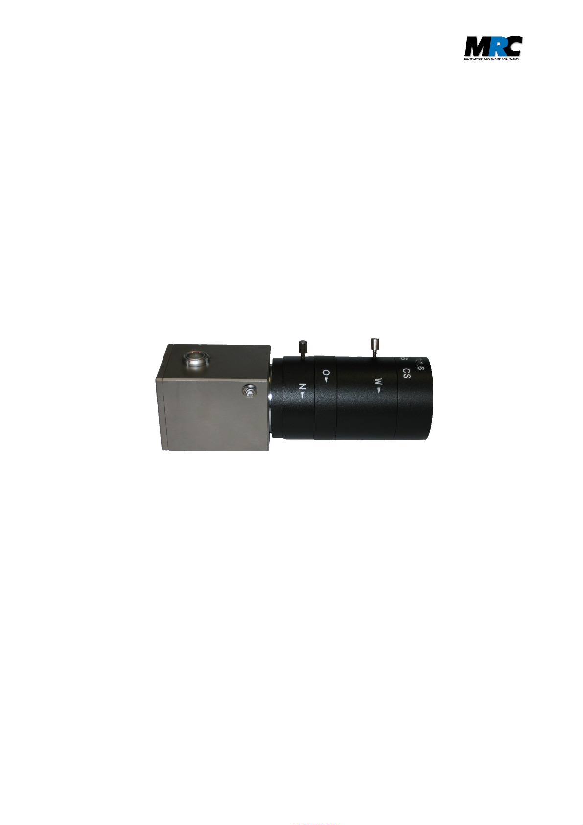
3. Video camera and vario lens
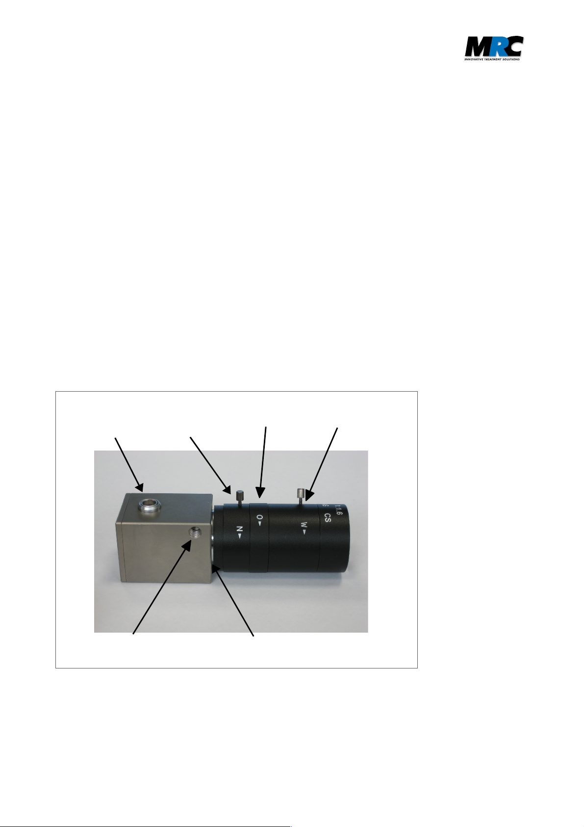
Figure 1 shows the camera housing and the connected vario lens.
Video
connector
Mounting thread
Focus
adjustment
Aperture
CS-lens mount
Focal length /
Magnification
Figure 1:
Video camera and
vario lens
The lens is connected to the standard CS-lens mount in the housing. It has three operating controls:
• The focal length defines the magnification of the recorded images. It can be adjusted by rotating
the foremost ring (see figure 1).
MRC Systems GmbH version: 6 - 2010-12-03 page 2 of 6
Page 3

• The aperture controls the depth of sharpness. If the aperture is changed the camera electronics
automatically readjusts the amplification. Closing the aperture increases the depth of sharpness
and in that way the image quality.
• The focus adjustment ring serves for the manual refocusing.
The position of the focal length and focus adjustment rings can be fixed with two screws.
4. Connection of camera to filter box
The camera is connected to the filter box via the camera connection cable, which includes power
and signal lines as well as shielding.
The filter box includes a low pass filter that suppresses frequencies higher than 1 MHz with over
100 dB. This filter prevents damage and interferences caused by the high frequency signals of the
MR scanner.
camera
connector
Figure 2: Filter box (front side)
5. Filter box installation
For a permanent installation, the filter box should be screwed onto the panel board by means of the
feed through camera connector (see figure 2). Figure 3 illustrates the recommended configuration:
• A 12 mm through hole in the panel board is required.
• The camera connector is guided through this hole.
• The camera connector provides the ground connection to the shielding of the MR cabinet.
For temporary use, the camera cable can be brought into the MR cabinet by other means, e.g.
through a service entry hole (“waveguide”). In this case, an additional grounding cable should be
used to connect the camera connector to the shield panel grounding. The camera connector must
completely protrude into the MR cabinet and the video cable must not jut out.
MRC Systems GmbH version: 6 - 2010-12-03 page 3 of 6
Page 4

Figure 3: Device and cable configuration
6. Connection of power supply
The power for the camera is transmitted via the camera connector cable. Therefore, the power
supply is connected to the filter box (see figure 4). The required power values are 200 mA, 6-12V.
video
connector
power
supply
Figure 4: Filter box (rear side)
7. Connection to TV set / VCR / frame grabber
A BNC/Cinch adapter and a standard Cinch cable are used to transfer the video output signal to a
TV set, VCR, frame grabber, or video card. The Cinch cable is plugged to the video connector at
the filter box (see figure 4).
The video signal can be directly viewed with a TV or recorded with a VCR. To view and store the
images with a PC, the Cinch cable must be connected to a frame grabber or video card within the
PC. Any software for analog video viewing should be appropriate to process the signals.
MRC Systems GmbH version: 6 - 2010-12-03 page 4 of 6
Page 5

8. Mounting options
There are different mounting options for the camera. The standard configuration makes use of the
wall-mount included in delivery (see figure 5).
Figure 5: Camera mounted with wall-mount
An alternative setup is to mount the camera on a tripod using the mounting thread in the camera
housing (see figure 6).
Figure 6: Camera mounted on a tripod
MRC Systems GmbH version: 6 - 2010-12-03 page 5 of 6
Page 6

9. Technical Data
Sensor Type: B/W or color CMOS Sensor 1/3 inch
Output: EIA(NTSC) video signal with 60Hz half frame rate
or CCIR(PAL) video signal with 50Hz half frame rate
Sensitivity: 0.2Lux for f#1.2 (B/W)
Spectral sensitivity (B/W camera)
Housing dimensions
Dimensions: 36mm x 36mm x 125mm (incl. lens 6-60mm fl)
Connector for lens: CS-Mount 1 inch, 32 threads/inch(UN-2A)
Mounting thread: 1/4 inch
Weight: 325g
Lens
Type: Vario Lens with manual iris and focus
Mount: CS
Focal length: 6-60mm (lenses with other focal lengths on request)
Aperture range: 1.6-closed
Minimal object distance: 1 m (depending on applied focal length)
Elektronics
Power supply: 200 mA, 6-12V DC
Output impedance: 75Ω
10. Contact
MRC Systems GmbH
Hans-Bunte-Strasse 10
D-69123 Heidelberg
Germany
phone: +49-6221-13803-00
fax: +49-6221-13803-01
mail: info@mrc-systems.de
MRC Systems GmbH version: 6 - 2010-12-03 page 6 of 6
 Loading...