

Page 1
Operator’s Guide
Portable 2-Input Diversity Receiver
MDR-2
Manual Part No. 400526-1
Rev. B December 2007
Page 2

Page 3

Notices
Notices Notices-iMDR-2 Operator’s Guide
About This Manual
Part number 400526-1
Revision B December 2007
The information in this manual applies to the Microwave Radio
Communications (MRC) MDR-2 Portable 2-Input Diversity
Receiver system.
Copyright
The information in this manual may only be reproduced by the
purchaser strictly for its own internal use to the extent required
for its use of the product, and shall only be made available to
purchaser's employees who need access to this material. No
part of this material, nor any copies hereof, shall in any manner
be disclosed, disseminated, or made available by the purchaser
or its employees to any other person, firm, or entity without the
express prior written consent of Microwave Radio
Communications, nor shall the same in any manner be modified
or published for resale without the express prior written
authorization of Microwave Radio Communications.
© 2007 Microwave Radio Communications
Microwave Radio Communications
101 Billerica Avenue - Bldg. 6
North Billerica, MA 01862-1256 USA
TEL: 800.490.5700
978.671.5700
FAX: 978.671.5800
Printed in U.S.A.
Proprietary Material
The information and design contained within this manual was
originated by and is the property of Microwave Radio
Communications. Microwave Radio Communications reserves
all patent proprietary design, manufacturing, reproduction use,
and sales rights thereto, and to any articles disclosed therein,
except to the extent rights are expressly granted to others. The
foregoing does not apply to vendor proprietary parts.
Microwave Radio Communications has made every effort to
ensure the accuracy of the material contained in this manual at
the time of printing. As specifications, equipment, and this
manual are subject to change without notice, Microwave Radio
Communications assumes no responsibility or liability
whatsoever for any errors or inaccuracies that may appear in this
manual or for any decisions based on its use. This manual is
supplied for information purposes only and should not be
construed as a commitment by Microwave Radio
Communications.
Quality Certification
Microwave Radio Communications is certified to ISO 9001:2000.
Authorized EU representative: Vislink PLC.
Page 4
Notices Notices-iiMDR-2 Operator’s Guide
Conventions
Pay special attention to information marked in one of the
following ways:
WARNING
Follow WARNINGS closely to prevent
personal injury or death.
CAUTION
Follow CAUTIONS to prevent damage to
the equipment.
Note
Notes provide additional information to assist you
in using and maintaining the equipment.
Waste Electrical and Electronic
Equipment
The crossed out dustbin symbol on the product
indicates that the product must not be disposed of
with other waste at the end of its life cycle. Instead, it
is the user’s responsibility to dispose of the waste
equipment by handing it over to a designated collection point for
the recycling of Waste Electrical and Electronic Equipment
(WEEE). For more information about where you can drop off
your waste equipment for recycling, please contact your local
government office.
Except for this notification and the proper marking of products
with the appropriate symbol, Microwave Radio Communications
disclaims responsibility for the disposal of its products per the
WEEE directive.
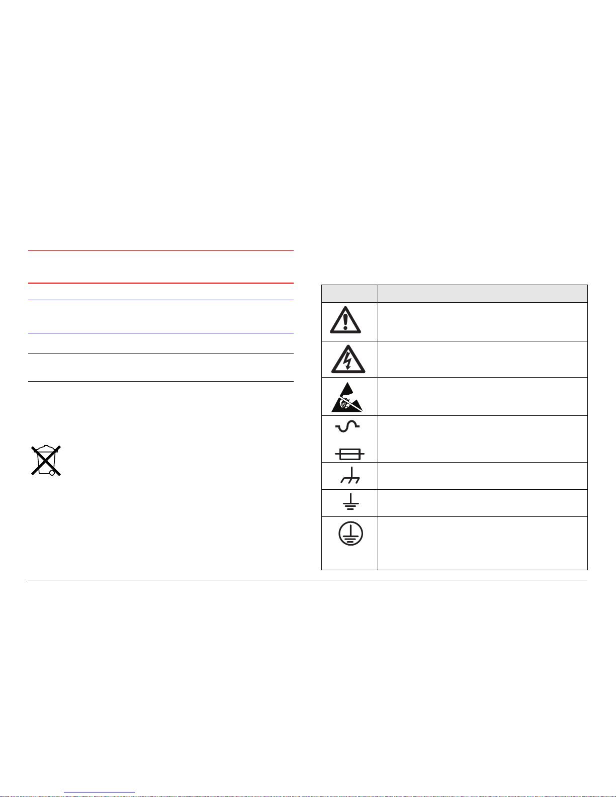
Symbols Used
The following symbols are used on the equipment:
Symbol Meaning
WARNING: General Warning. Risk of Danger
WARNING: Risk of Electric Shock
CAUTION: Electrostatic Discharge. Possible
Damage to Equipment
-OR-
Fuse - Identifies fuses or their location.
Frame or Chassis Ground - Identifies the frame or
chassis terminal.
Earth Ground - Identifies the earth ground terminal
Protective Earth Ground - Identifies any terminal
which is intended for connection to an external
conductor for protection against electric shock in
case of a fault, or the terminal on a protective earth
electrode.
Page 5

Notices Notices-iiiMDR-2 Operator’s Guide
On-Line Viewing
Text displayed as blue contains a hypertext link. Click on the
hypertext to jump to that destination. Click on the
blue destination to return.
Warranty Information
Products Manufactured by MRC
a. Products manufactured by MRC are warranted against
defects in material and workmanship for a period of two (2) years
from date of delivery, as evidenced by MRC's packing slip or
other transportation receipt (unless otherwise noted).
b. MRC's sole responsibility under this warranty will be to either
repair or replace, at its option, any component which fails during
the applicable warranty period because of a defect in material or
workmanship, provided Buyer has promptly reported same to
MRC in writing. All replaced products and parts will become
MRC's property.
c. MRC will honor the warranty at the repair facility designated
by MRC. It is Buyer's responsibility to return, at its expense, the
allegedly defective product to MRC. Buyer must obtain a Return
Viewing this manual on-line
requires Acrobat® or Adobe®
Reader®, Version 5.0 and later.
Click on this icon to download
your FREE copy of Adobe®
Reader®.
Material Authorization (RMA) number and shipping instructions
from MRC prior to returning any product under warranty.
Transportation charges for the return of the product to Buyer will
be paid by MRC within the United States. For all other locations,
the warranty excludes all costs of shipping, customs clearance
and other related charges. If MRC determines that the product is
not defective within the terms of this warranty, Buyer will pay
MRC all costs of handling, transportation, and repairs at the then
prevailing repair rates.
d. All the above warranties are contingent upon proper use of
the product. These warranties will not apply (1) if adjustment,
repair, or product or parts replacement is required because of
accident, unusual physical, electrical or electromagnetic stress,
neglect, misuse, failure of electric power, environmental controls,
transportation, failure to maintain properly or otherwise in
accordance with MRC specifications, or abuses other than
ordinary use; (2) if the product has been modified by Buyer or
has been repaired or altered outside MRC's repair facility, unless
MRC specifically authorizes such repairs or alterations in each
instance; or (3) where MRC serial numbers, warranty data or
quality assurance decals have been removed or altered.
e. Equipment shipped FOB from Microwave Radio
Communications shall become the property of the buyer upon
delivery and receipt from the carrier. Any damage in shipment
should be handled by the buyer directly with the carrier.
Immediately request the carrier’s inspection upon evidence of
damage during shipment. Do not return any Microwave Radio
Communications product to the factory until a Return Material
Authorization (RMA) number and shipping instructions have
been provided.
f. No person, including any dealer, agent or representative of
MRC is authorized to assume for MRC any other liability on its
behalf except as set forth herein. If any payment is due MRC for
Page 6

Notices Notices-ivMDR-2 Operator’s Guide
services performed hereunder, it will be subject to the same
payment terms as the original purchase.
Products Manufactured By Others
For products not manufactured by MRC, the original
manufacturer's or licensor's warranty will be assigned to Buyer to
the extent permitted by the manufacturer or licensor and is in lieu
of any other warranty, expressed or implied. For warranty
information on a specific product, a written request should be
made to MRC.
All Products
THE FOREGOING WARRANTIES AND REMEDIES ARE
EXCLUSIVE AND ARE IN LIEU OF ALL OTHER EXPRESS OR
IMPLIED WARRANTIES, OBLIGATIONS, AND LIABILITIES ON
THE PART OF MRC. EXCEPT FOR THE EXPRESS
WARRANTIES STATED HEREIN, MRC DISCLAIMS ALL
WARRANTIES ON PRODUCTS FURNISHED HEREUNDER,
INCLUDING, WITHOUT LIMITATION, ALL IMPLIED
WARRANTIES OF MERCHANTABILITY AND FITNESS FOR A
PARTICULAR PURPOSE. MRC WILL HAVE NO
RESPONSIBILITY FOR ANY PARTICULAR APPLICATION
MADE OF ANY EQUIPMENT.
Any description of equipment, whether in writing or made orally
by MRC or its agents, specification sheets, models, bulletins,
drawings, or similar materials used in connection with Buyer's
order are for the sole purpose of identifying the equipment and
will not be construed as an express warranty. Any suggestions
by MRC or its agents regarding use, application, or suitability of
the equipment will not be construed as an express warranty. No
warranties may be implied from any course of dealing or usage
of trade. Buyer agrees that the exclusion of all warranties, other
than those expressly provided herein, is reasonable.
Page 7

Contents
Contents Contents-1MDR-2 Operator’s Guide
Introduction - - - - - - - - - - - - - - - - - - - - - - - - - 1-1
Chapter Overview - - - - - - - - - - - - - - - - - - - - - - - - - 1-1
How to Use This Manual - - - - - - - - - - - - - - - - - - - - 1-1
What This Manual Covers - - - - - - - - - - - - - - - - - - - 1-1
How They’re Organized - - - - - - - - - - - - - - - - - - - - - 1-1
For Whom It’s Written - - - - - - - - - - - - - - - - - - - - - - 1-2
Related Documents - - - - - - - - - - - - - - - - - - - - - - - - 1-2
Ordering Documentation - - - - - - - - - - - - - - - - - - - - 1-2
Calling for Service - - - - - - - - - - - - - - - - - - - - - - - - - 1-3
Supported Repairs - - - - - - - - - - - - - - - - - - - - - - - - 1-3
Tell Us What You Think! - - - - - - - - - - - - - - - - - - - - 1-3
Product Description- - - - - - - - - - - - - - - - - - - 2-1
Chapter Overview - - - - - - - - - - - - - - - - - - - - - - - - - 2-1
Description - - - - - - - - - - - - - - - - - - - - - - - - - - - - - - 2-1
Options - - - - - - - - - - - - - - - - - - - - - - - - - - - - - - 2-2
Power Options - - - - - - - - - - - - - - - - - - - - - - - - - 2-2
Mounting and Deployment Options - - - - - - - - - - 2-2
System Integration - - - - - - - - - - - - - - - - - - - - - - 2-3
System Components - - - - - - - - - - - - - - - - - - - - - - - 2-3
MDR-2 - - - - - - - - - - - - - - - - - - - - - - - - - - - - - - 2-3
Block Down Converters- - - - - - - - - - - - - - - - - - - 2-4
STRATA RX Remote Control Panel - - - - - - - - - - 2-4
STRATA AC to DC Power Supply - - - - - - - - - - - 2-5
For More Information - - - - - - - - - - - - - - - - - - - - - - - 2-5
Routine Operation - - - - - - - - - - - - - - - - - - - - 3-1
Chapter Overview - - - - - - - - - - - - - - - - - - - - - - - - - 3-1
Overview of Controls, Indicators and Connectors - - - 3-1
MDR-2 Controls, Indicators, and Connectors - - - 3-1
Block Down Converter Indicators and Connectors 3-4
ACU Controls, Indicators, and Connectors - - - - - 3-5
Preparing for Operation - - - - - - - - - - - - - - - - - - - - - 3-6
Mobile Installation - - - - - - - - - - - - - - - - - - - - - - - 3-6
Portable Deployment - - - - - - - - - - - - - - - - - - - - - 3-6
Powering the MDR-2 - - - - - - - - - - - - - - - - - - - - - 3-9
Using the Display Screens - - - - - - - - - - - - - - - - - - 3-10
Monitoring Options - - - - - - - - - - - - - - - - - - - - - - - 3-11
Monitoring Link Quality (LQ) - - - - - - - - - - - - - - 3-12
LQ Action Levels - - - - - - - - - - - - - - - - - - - - - - - 3-13
What Actions to Take- - - - - - - - - - - - - - - - - - - - 3-14
Monitoring Bit Error Ratio (BER) - - - - - - - - - - - 3-15
Monitoring Signal-to-Noise Ratio (SNR)- - - - - - - 3-16
Control Operations - - - - - - - - - - - - - - - - - - - - - - - - 3-17
Changing a Preset- - - - - - - - - - - - - - - - - - - - - - 3-17
Setting a Channel and Offset - - - - - - - - - - - - - - 3-19
Set OFDM Bandwidth - - - - - - - - - - - - - - - - - - - 3-20
Select DC On Coax - - - - - - - - - - - - - - - - - - - - - 3-20
Front Panel vs. MDR Configuration Utility Settings - 3-21
Troubleshooting - - - - - - - - - - - - - - - - - - - - - 4-1
Chapter Overview - - - - - - - - - - - - - - - - - - - - - - - - - 4-1
Status LED - - - - - - - - - - - - - - - - - - - - - - - - - - - - - - 4-1
Display Messages - - - - - - - - - - - - - - - - - - - - - - - - - 4-2
Error Codes - - - - - - - - - - - - - - - - - - - - - - - - - - - - - - 4-3
Error Status - - - - - - - - - - - - - - - - - - - - - - - - - - - 4-3
Primary Error Code - - - - - - - - - - - - - - - - - - - - - - 4-3
Operational Problems - - - - - - - - - - - - - - - - - - - - - - - 4-6
Channels and Frequencies - - - - - - - - - - - - - A-1
Appendix Overview - - - - - - - - - - - - - - - - - - - - - - - - A-1
Initial Factory Presets - - - - - - - - - - - - - - - - - - - - - - - A-1
1.7 to 1.85 GHz Channel Plan - - - - - - - - - - - - - - A-1
1.9 to 2.2 GHz Channel Plan - - - - - - - - - - - - - - - A-2
2.2 to 2.5 GHz Channel Plan - - - - - - - - - - - - - - - A-2
2.3 to 2.7 GHz Channel Plan - - - - - - - - - - - - - - - A-2
3.4 to 3.6 GHz Channel Plan - - - - - - - - - - - - - - - A-2
3.4 to 3.8 GHz Channel Plan - - - - - - - - - - - - - - - A-3
Page 8

Contents Contents-2MDR-2 Operator’s Guide
3.5 to 3.9 GHz Channel Plan - - - - - - - - - - - - - - - A-3
4.4 to 4.7 GHZ Channel Plan - - - - - - - - - - - - - - - A-3
4.8 to 5.0 GHz Channel Plan - - - - - - - - - - - - - - - A-4
US 2 GHz Reallocation - 12 MHz Channel Plan - - - - A-4
Glossary - - - - - - - - - - - - - - - - - - - - - - - - - - - B-1
Link Quality - - - - - - - - - - - - - - - - - - - - - - - - - C-1
Appendix Overview - - - - - - - - - - - - - - - - - - - - - - - - C-1
Analog vs. Digital Systems - - - - - - - - - - - - - - - - - - - C-1
Understanding Link Quality - - - - - - - - - - - - - - - - - - C-2
Description - - - - - - - - - - - - - - - - - - - - - - - - - - - C-2
The LQ Scale - - - - - - - - - - - - - - - - - - - - - - - - - - C-2
LQ and Signal Quality - - - - - - - - - - - - - - - - - - - - C-3
LQ Action Levels - - - - - - - - - - - - - - - - - - - - - - - C-3
What Actions to Take - - - - - - - - - - - - - - - - - - - - C-4
Technical Background: LQ Factors - - - - - - - - - - - - - C-5
Received Signal Strength and Signal-to-Noise
Ratio - - - - - - - - - - - - - - - - - - - - - - - - - - - - - - - - C-5
Forward Error Correction - - - - - - - - - - - - - - - - - C-5
Guard Interval - - - - - - - - - - - - - - - - - - - - - - - - - C-5
Bandwidth - - - - - - - - - - - - - - - - - - - - - - - - - - - - C-6
Bit Error Rate - - - - - - - - - - - - - - - - - - - - - - - - - - C-6
Maximal Ratio Combining - - - - - - - - - - - - - - D-1
Appendix Overview - - - - - - - - - - - - - - - - - - - - - - - - D-1
Antenna Correlation- - - - - - - - - - - - - - - - - - - - - - - - D-1
Maximal Ratio Combining - - - - - - - - - - - - - - - - - - - D-1
Specifications - - - - - - - - - - - - - - - - - - - - - - - E-1
Page 9
1
Introduction 1-1MDR-2 Operator’s Guide
Introduction
1.1 Chapter Overview
This chapter will introduce you to the Operator’s Guide - what it
covers, how it’s organized, and for whom it’s written.
1.2 How to Use This Manual
This manual was prepared to be viewed on a Windows®-based
PC. A pdf file for this manual is provided on the CD ROM
delivered with each MDR-2 Portable 2-Input Diversity Receiver
system. The CD ROM contains pdf files for the Operator’s
Guide, the Technical Reference Manual, and the Quick
Reference Cards. Hardcopies of the Operator’s Guide, the
Technical Reference Manual, and the Quick Reference Cards
are also delivered with each MDR-2.
Viewing of this manual on-line requires Acrobat® or Adobe®
Reader®, Version 5.0 and later. Click on the following icon to
download your FREE copy of Adobe® Reader®.
When viewing this manual on-line, text displayed as blue
contains a hypertext link. Click on the blue hypertext link to
jump to that destination. If the destination link is also blue, click
on the blue destination link to return.
1.3 What This Manual Covers
This manual covers how to operate the MDR-2 Portable 2-Input
Diversity Receiver system.
The MDR-2 system consists of the following:
• Portable 2-Input Diversity Receiver
• Two Block Down Converters
For mobile applications, such as in a vehicle or in an aircraft, the
MDR-2 is usually mounted in a bulkhead or compartment. For
portable operation, the MDR-2 can be mounted on a tripod.
The MDR-2 operates on DC power, supplied externally, from
+10.5 to +36 VDC. This power can be supplied from an optional
STRATA AC to DC Power Supply (ACU) or from another DC
power source.
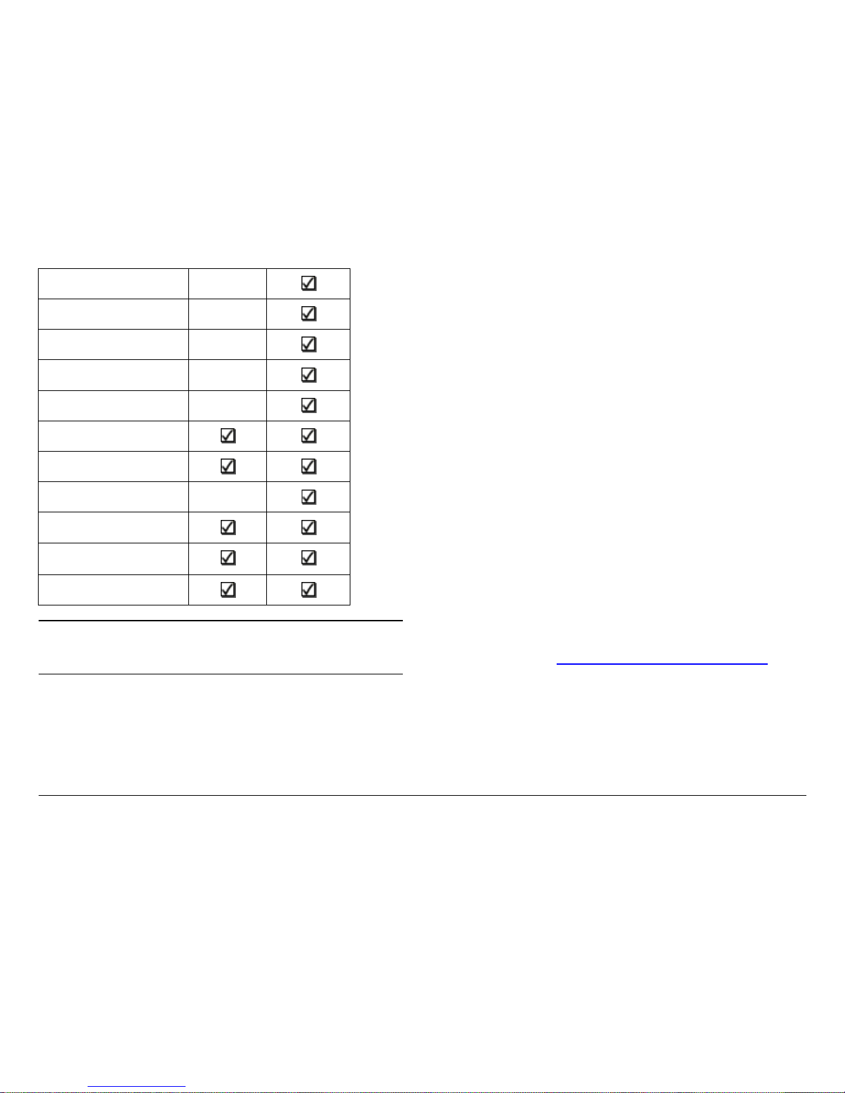
1.4 How They’re Organized
The manuals for the MDR-2 are organized as follows:
Chapter
Operator’s
Guide
Technical
Reference
Manual
Introduction
Product Description
Routine Operation
Troubleshooting
Page 10
Introduction 1-2MDR-2 Operator’s Guide
Note
The Technical Reference Manual contains
everything in the Operator’s Guide, plus additional
technical content.
1.5 For Whom It’s Written
This manual is intended for use by personnel assigned to
operate the MDR-2. Users of this manual should already be
familiar with basic concepts of radio, video, and audio.
Advanced Operation
Installation
Repair
Replacement Parts
Theory of Operation
Channels & Frequencies
Glossary
Configurator Reference
Link Quality
Maximum Ratio
Combining Techniques
Specifications
1.6 Related Documents
• Portable 2-Input Diversity Receiver Technical Reference
Manual
(part no. 400527-1)
• Portable 2-Input Diversity Receiver Quick Reference Card
(part no. 400528-1)
1.7 Ordering Documentation
Any of the above manuals may be ordered by contacting MRC
Customer Service:
Business Hours: Monday - Thursday
8:00 AM - 7:00 PM Eastern Time (US)
(0800 - 1900 hrs US ET)
Friday
8:00 AM - 5:00 PM Eastern Time (US)
(0800 - 1700 hrs US ET)
Telephone: 800-490-5700 (Press 3)
978-671-5700 (Press 3)
Fax: 978-671-5948
E-mail customerservice@mrcbroadcast.com
When contacting Customer Service, please have the following
information available:
• Model number and serial number of the unit. This is
located on a label on the bottom of each unit
• Approximate purchase date
Page 11

Introduction 1-3MDR-2 Operator’s Guide
• Radio version, which appears on the MDR-2
alphanumeric display at startup
- OR -
• Module versions displayed on the Radio page of the MDR
Configuration Utility, when the MDR Configuration Utility
software is connected to the MDR-2
1.8 Calling for Service
MRC Technical Support is available 24 hours a day, 7 days a
week. During regular business hours you can reach our expert
staff directly.
Business Hours: Monday - Friday
8:00 AM - 7:00PM Eastern Time (US)
(0800 - 1900 hrs US ET)
Telephone: 800-490-5700 (Press 4)
978-671-5700 (Press 4)
Fax: 978-671-5948
E-mail: technicalsupport@mrcbroadcast.com
After regular business hours and on weekends and holidays, you
can also reach our expert staff as follows:
Telephone: 978-671-5929
Your call will be automatically forwarded to the on-call Technical
Support specialist.
When contacting Technical Support, please have the following
information available:
• Model number and serial number of the unit. This is
located on a label on the bottom of each unit
• Approximate purchase date
• Radio version, which appears on the MDR-2
alphanumeric display at startup
- OR -
• Module versions displayed on the Radio page of the MDR
Configuration Utility, when the MDR Configuration Utility
software is connected to the MDR-2
1.9 Supported Repairs
The MDR-2 and Block Down Converters require specialized test
equipment to calibrate amplitude and frequency characteristics
after repair. In addition, sealing the MDR-2 and the Block Down
Converter enclosures after repair requires exacting techniques
and special fixtures to ensure weather resistance of the units.
There are NO supported field repairs for either the MDR-2 or
the Block Down Converters.
Return the entire unit(s) for factory repair.
If you attempt field repair, you risk damaging your
equipment. If your equipment is under warranty, you may also
affect your warranty coverage.
1.10 Tell Us What You Think!
We’d appreciate any comments or suggestions you have about
this manual. The more feedback we get, the better the manuals
get!
Page 12

Introduction 1-4MDR-2 Operator’s Guide
If you’re viewing this manual electronically, it’s easy - just click on
the link below to send us an E-mail.
Or, you can E-mail our Technical Support team at:
technicalsupport@mrcbroadcast.com
Be sure to tell us what product you’re writing about, and which
manual - the Operator’s Guide, the Quick Reference Card, or the
Technical Reference Manual.
Feedback
Page 13
2
Product Description 2-1MDR-2 Operator’s Guide/Tech Ref Manual
Product Description
2.1 Chapter Overview
This chapter provides an overall description of the MDR-2
Portable 2-Input Diversity Receiver system, its components,
options, and capabilities.
Here are the topics covered:
Topic Page
Description
2-1
Options
2-2
Remote Control Options 2-2
Antenna Options
2-2
Frequency Bands 2-2
Block Down Converters 2-2
Power Options 2-2
Mounting and Deployment Options
2-2
Mobile Installation 2-2
Portable Deployment 2-3
System Integration
2-3
System Operation 2-3
System Configuration 2-3
System Components
2-3
MDR-2
2-3
Block Down Converters
2-4
STRATA RX Remote Control Panel 2-4
STRATA AC to DC Power Supply 2-5
For More Information 2-5
2.2 Description
The MDR-2 system is a highly reliable, flexible, and compact
portable microwave diversity receiver ideal for tripod or mobile
installations. The MDR-2 is ideal for Electronic News Gathering
(ENG), Digital Video Broadcast (DVB), mobile communication,
wireless airborne networks, and Outside Broadcast (OB)
systems.
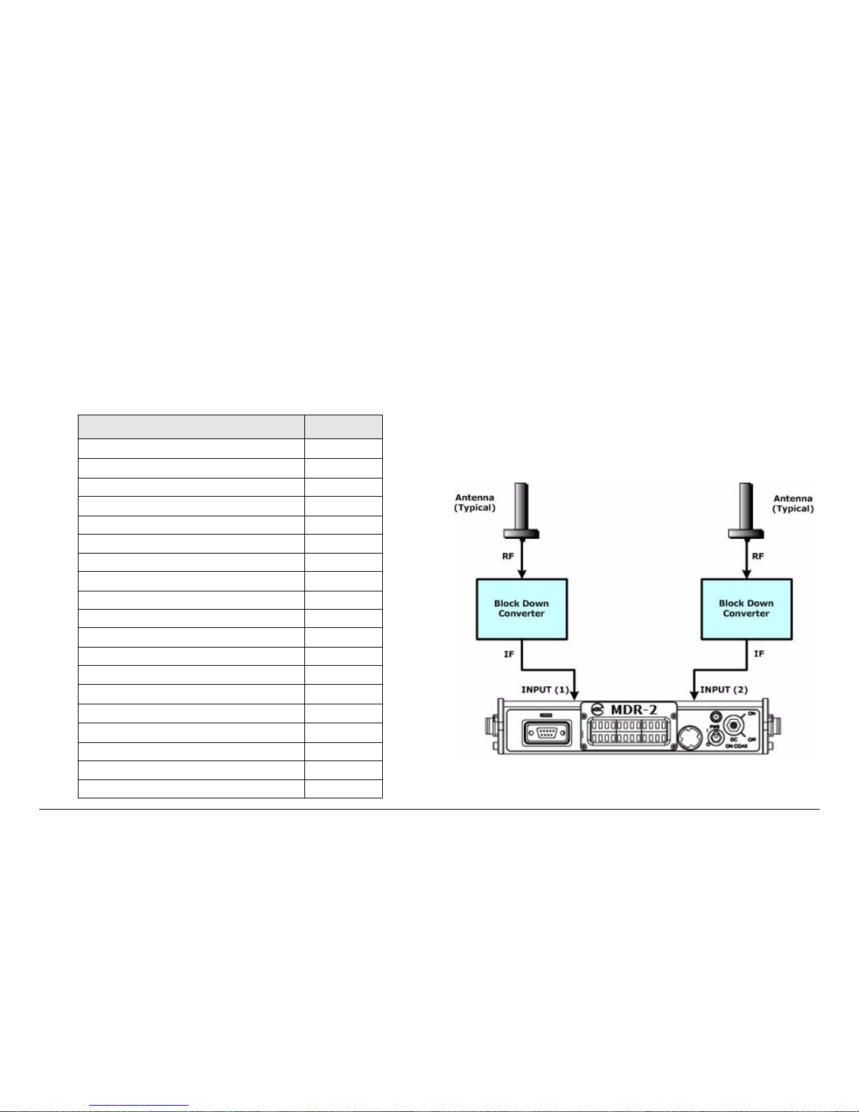
The MDR-2 system consists of the MDR-2 Portable 2-Input
Diversity Receiver, two Block Down Converters, and optional
omni antennas. See Figure 2-1.
Figure 2-1: MDR-2 System Block Diagram
Page 14

Product Description 2-2MDR-2 Operator’s Guide/Tech Ref Manual
The MDR-2 architecture allows you flexibility in configuration,
siting, and operation. MDR-2 key features are as follows:
• Supports Maximal Ratio Combining (MaxRC) diversity
technique
• Utilizes two UHF inputs for tuning
• MPEG decoding and COFDM demodulation
• NTSC and PAL system decoding capabilities
• Block Down Converters compatible with standard omni
and directional antennas
2.2.1 Options
MDR-2 options (typically) consist of the following:
Remote Control Options For portable mobile or airborne
operations, the MDR-2 may be controlled by the optional
STRATA RX Remote Control Panel. The STRATA Remote
Control Panel is mounted in a mobile rack or in an aircraft
instrument panel and is connected via an RS-232 cable between
the Remote Control Panel and the MDR-2.
Antenna Options The MDR-2 is compatible with the MRC
family of omnidirectional receiver antennas. Contact your Sales
Representative to explore antenna choices available.
Frequency Bands The MDR-2 can be ordered to operate on
the following frequency bands:
1.7 to 1.85 GHz 3.4 to 3.8 GHz
1.9 to 2.2 GHz 3.5 to 3.9 GHz
2.2 to 2.5 GHz 4.4 to 4.7 GHz
2.3 to 2.7 GHz 4.8 to 5.0 GHz
3.2 to 3.6 GHz
Block Down Converters MRC Block Down Converters are
available to operate in the following frequency bands.
1.7 to 1.85 GHz 3.4 to 3.8 GHz
1.9 to 2.2 GHz 3.5 to 3.9 GHz
2.2 to 2.5 GHz 4.4 to 4.7 GHz
2.3 to 2.7 GHz 4.8 to 5.0 GHz
3.2 to 3.6 GHz
The MDR-2 may only be used with the MRC Block Down
Converters. The Block Down Converters must be ordered for
the specific frequency band that you will be using for normal
operation.
2.2.2 Power Options
The MDR-2 operates on +10.5 to +36.0 VDC power, supplied
externally. This DC power can be supplied by the optional
STRATA AC to DC Power Supply (ACU) or from another DC
power source. Power to the Block Down Converters is provided
via DC on coax from the MDR-2.
2.2.3 Mounting and Deployment Options
The MDR-2 offers a number of options for mobile or portable
deployment applications.
For more details on installation of the MDR-2 in various
applications, refer to the “Installation” Chapter on page 6-1 (part
of the Portable 2-Input Diversity Receiver Technical Reference
Manual only).
Mobile Installation For mobile applications such as in a vehicle
or an aircraft, the MDR-2 is usually mounted in an MRC fixed
mounting bracket and is installed in a bulkhead or compartment.
Page 15

Product Description 2-3MDR-2 Operator’s Guide/Tech Ref Manual
The cabling is permanently installed and power comes from
vehicle or aircraft power.
Portable Deployment In portable applications, the MDR-2 will
be moved from place to place and set up each time and will
usually be mounted on an MRC Quick Release Mount for easy
attachment to an MRC tripod. The Quick Release Mount
connects to a Dovetail Adapter Plate machined into the MRC
tripod mount. Other mounting options are available.
Refer to the “Installation” Chapter on page 6-1 (part of the
Portable 2-Input Diversity Receiver Technical Reference Manual
only) for additional information.
Power, antenna, and audio/video connections are removed at
the end of each deployment.
2.2.4 System Integration
System Operation Once the MDR-2 is connected and powered
up, system settings can be selected or modified from the MDR-2
front panel.
System Configuration The MDR-2 offers two levels of system
configurations designed to match the needs of different
personnel.
For the field operator, the MDR-2 has up to nine Presets that can
be selected from the front panel. Each Preset controls key
parameters such as channel and bandwidth.
For the advanced operator and technical staff, the MDR
Configuration Utility software allows complete control of
parameters in the MDR-2. The MDR Configuration Utility
software runs on a Windows-based PC and connects to the
MDR-2 via an RS-232 null modem cable.
Interfacing a PC to the MDR-2 provides complete control of the
MDR-2 Presets. You can read the current settings, program new
settings, or return the units to their factory default settings.
2.3 System Components
This section will provide more details about each of the
components of a (typical) MDR-2 system:
• MDR-2 Portable 2-Input Diversity Receiver
• Block Down Converters
• STRATA RX Remote Control Unit
• STRATA AC to DC Power Supply (ACU)
For details on connections between the MDR-2 components,
refer to the “Installation” Chapter on page 6-1 (part of the
Portable 2-Input Diversity Receiver Technical Reference Manual
only).
2.3.1 MDR-2
In telecommunications, diversity reception is one method of
improving the reception of transmitted signals by receiving and
processing multiple versions of the same signal.
The MDR-2, as shown in Figure 2-2, is a versatile, portable,
digital diversity receiver system designed to accept two
microwave radio signals. Using two MRC Block Down
Converters, multipath microwave signals are received,
combined, and converted to a single output signal.
Figure 2-2: MDR-2
MDR-2
Page 16
Product Description 2-4MDR-2 Operator’s Guide/Tech Ref Manual
The MDR-2 utilizes two Block Down Converters and two
separate antennas to receive transmitted signals. The Block
Down Converters are connected to the MDR-2 SIGNAL A and
SIGNAL B rear panel input connectors via coaxial cables. Only
MRC Block Down Converters can be used with the MDR-2.
Using two omni receiving antennas helps eliminate multipath
distortion. The diversity receiver receives the transmitted signal
on two antennas having different locations.
In situations where one antenna might experience poor
reception, the second antenna might not experience the same
poor reception. By using the MDR-2 receiver system, the right
antenna is chosen at the right moment and the MDR-2 operates
as though it receives a continuous quality signal.
With the MDR-2 receiver system, each signal has an individual
demodulator used to perform both the Fast Fourier Transform
(FFT) and channel equalization processes. Each demodulator
makes use of pilot carriers and other information about the input
signal to assess the condition of each individual carrier within the
COFDM spectrum. A weighting factor is then allocated relating
to the degradation of that carrier.
A diversity algorithm is then used to assess the weighting factors
for each input and can decide the ratio by which input carriers
are combined to produce the final output signal. This allows reconstruction of each individual carrier, providing the best
possible signal after demodulation and before the subsequent
error correction stages.
After demodulation and decoding, the receiver provides outputs
consisting of composite video (CV), audio, and digitized data
streams in ASI/SDI versions.
2.3.2 Block Down Converters
Two Block Down Converters, as shown in Figure 2-3, are used
with the MDR-2 receiver system. Each Block Down Converter
down-converts received RF frequency bands from 1.7 to 5.0
GHz to UHF bands of 448 to 861 MHz, a bandwidth of 413 MHz.
The Block Down Converter RF INPUT connector connects either
directly or via a type “N” 50 ohm coaxial cable to an omni
receiving antenna. The Block Down Converter IF OUTPUT
connector connects to the MDR-2 INPUT A or INPUT B TNC
connectors via 75 ohm coaxial cables. The coaxial cables
supplies DC on coax from the MDR-2 to provide power to the
Block Down Converter.
Figure 2-3: Block Down Converters
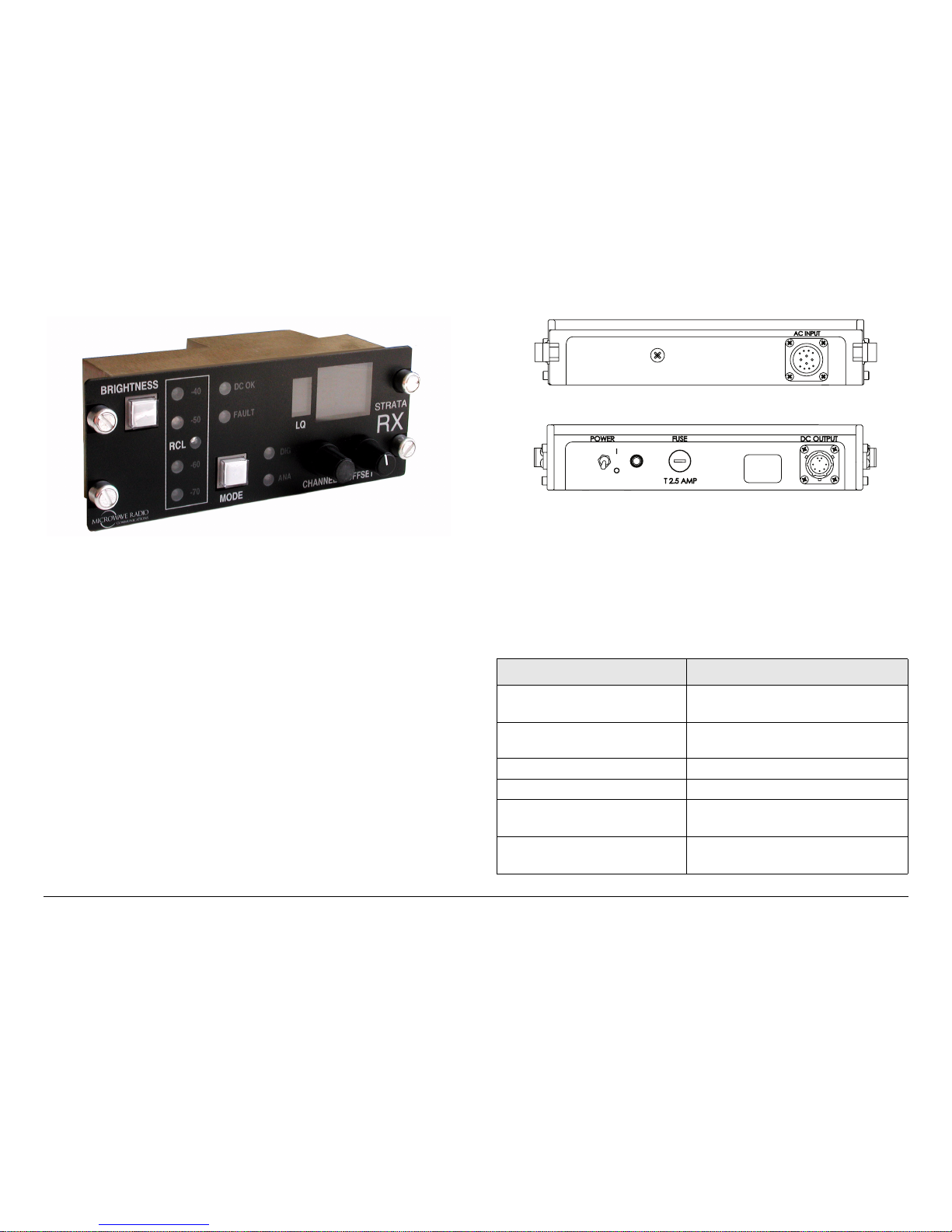
2.3.3 STRATA RX Remote Control Panel
For mobile or airborne operations, the STRATA RX Remote
Control Panel, as shown in Figure 2-4 on page 2-5, provides
simplified receive operations by allowing the operator to select
pre-configured Presets, channels, and offsets, depending upon
the required operating mode.
RF INPUT
PWR
A
B
BAND A/B
IF OUTPUT
Page 17
Product Description 2-5MDR-2 Operator’s Guide/Tech Ref Manual
Figure 2-4: STRATA RX Remote Control Panel
The STRATA RX Remote Control Panel provides instrument
panel remote control of the MDR-2 for vehicle or aircraft
operations and features nine selectable Presets. The STRATA
RX Remote Control Panel is connected to the MDR-2 via a
standard null modem cable.
For additional information, refer to the STRATA Remote Control
Panel Operator’s Guide (part no. 400489) or contact your Sales
Representative.
2.3.4 STRATA AC to DC Power Supply
For fixed or portable deployment applications, the MDR-2
System may be powered by the optional STRATA AC to DC
Converter (ACU). See Figure 2-5. The ACU is offered in several
different models, each featuring different voltage output levels.
For additional information, contact your Sales Representative.
The ACU installs as part of an integrated stack for either tripod or
fixed applications.
Figure 2-5: STRATA AC to DC Power Supply
2.4 For More Information
Additional detailed technical information about the MDR-2 is
contained in the Portable 2-Input Diversity Receiver Technical
Reference Manual. Specific topics contained in the Portable 2Input Diversity Receiver Technical Reference Manual are as
follows:
Topic Chapter
MDR Configuration Utility
Settings
See ”Advanced Operation” on
page 5-1
Connections to other
equipment
See ”Installation” on page 6-1
Installation See ”Installation” on page 6-1
Supported Repairs See ”Repair” on page 7-1
Repair Parts See ”Replacement Parts” on
page 8-1
Theory of Operation See ”Theory of Operation” on
page 9-1
OUTPUT
OUTPUT
< >
< >
DC
DC
Rear View
Front View
Page 18

Product Description 2-6MDR-2 Operator’s Guide/Tech Ref Manual
This page intentionally left blank.
Page 19

3
Routine Operation 3-1MDR-2 Operator’s Guide/Tech Ref Manual
Routine Operation
3.1 Chapter Overview
This chapter provides basic information that will enable you to
operate your MDR-2 Portable 2-Input Diversity Receiver.
Here are the topics covered:
Topic Page
Overview of Controls, Indicators and
Connectors
3-1
MDR-2 Controls, Indicators, and
Connectors
3-1
Block Down Converter Indicators and
Connectors
3-4
ACU Controls, Indicators, and
Connectors
3-5
Preparing for Operation 3-6
Mobile Installation 3-6
Portable Deployment 3-6
Powering the MDR-2 3-9
Using the Display Screens 3-10
Monitoring Options 3-11
Control Operations 3-17
Changing a Preset 3-17
Setting a Channel and Offset 3-19
Set OFDM Bandwidth 3-20
Select DC On Coax 3-20
Front Panel vs. MDR Configuration Utility
Settings
3-21
Information on settings made with the MDR Configuration Utility
software can be found in the “Advanced Operation” Chapter on
page 5-1 (part of the Portable 2-Input Diversity Receiver
Technical Reference Manual only).
For a summary of settings that can be made with the MDR-2
front panel control switch and which settings are made using the
MDR Configuration Utility software, see Section 3.7 on page 3-
21.
3.2 Overview of Controls, Indicators
and Connectors
This section describes the controls, indicators, and connectors
contained on the MDR-2 system.
3.2.1 MDR-2 Controls, Indicators, and
Connectors
Controls, indicators, and connectors contained on the MDR-2
are identified and described below. Topics covered are as
follows:
Topic Page
RS232 DB-9 Connector 3-2
Alphanumeric Display 3-2
Control Switch 3-2
Status LED 3-3
PWR Switch 3-3
DC ON COAX Switch 3-3
POWER Connector 3-4
Page 20
Routine Operation 3-2MDR-2 Operator’s Guide/Tech Ref Manual
Each of these controls, indicators, and connectors are described
in more detail in the following paragraphs. Controls, indicators,
and connectors contained on the MDR-2 front panel are shown
in Figure 3-1. Controls, fuses, and connectors contained on the
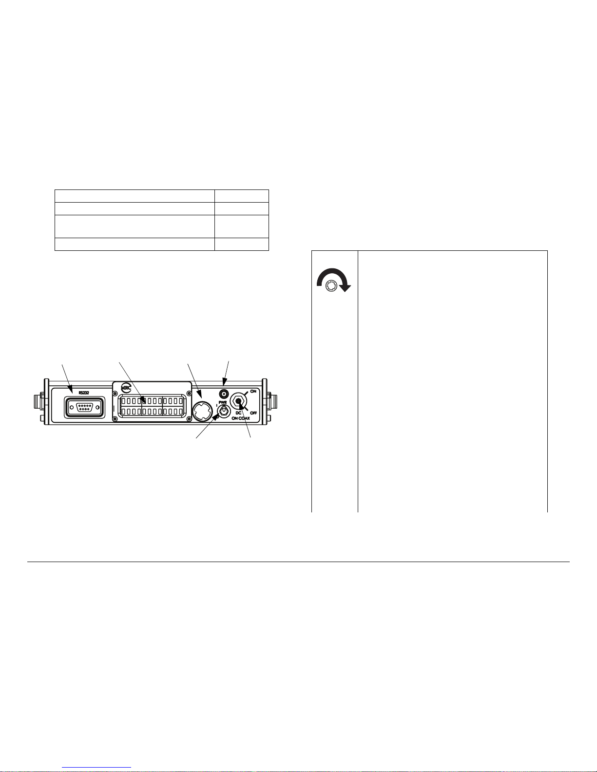
MDR-2 rear panel are shown in Figure 3-2 on page 3-4.
Figure 3-1: Front Panel Controls, Indicators, and
Connectors
RS232 DB-9 Connector The RS232 DB-9 connector provides
connections for factory test or to a Windows-based PC when
using the MDR Configuration Utility software. The connector
also provides Wayside data connections.
Alphanumeric Display The MDR-2 front panel contains a two-
line by 12-character alphanumeric display. The display works in
conjunction with the control switch to allow you to monitor
SIGNAL OUT BNC Connector 3-4
ASI MON BNC Connector 3-4
INPUT A and INPUT B TNC
Connectors
3-4
AUDIO Connector 3-4
MDR-2
RS232
Connector
Alphanumeric
Display
Control
Switch
Status
LED
DC ON COAX
Switch
PWR
Switch
system status and to control system settings.
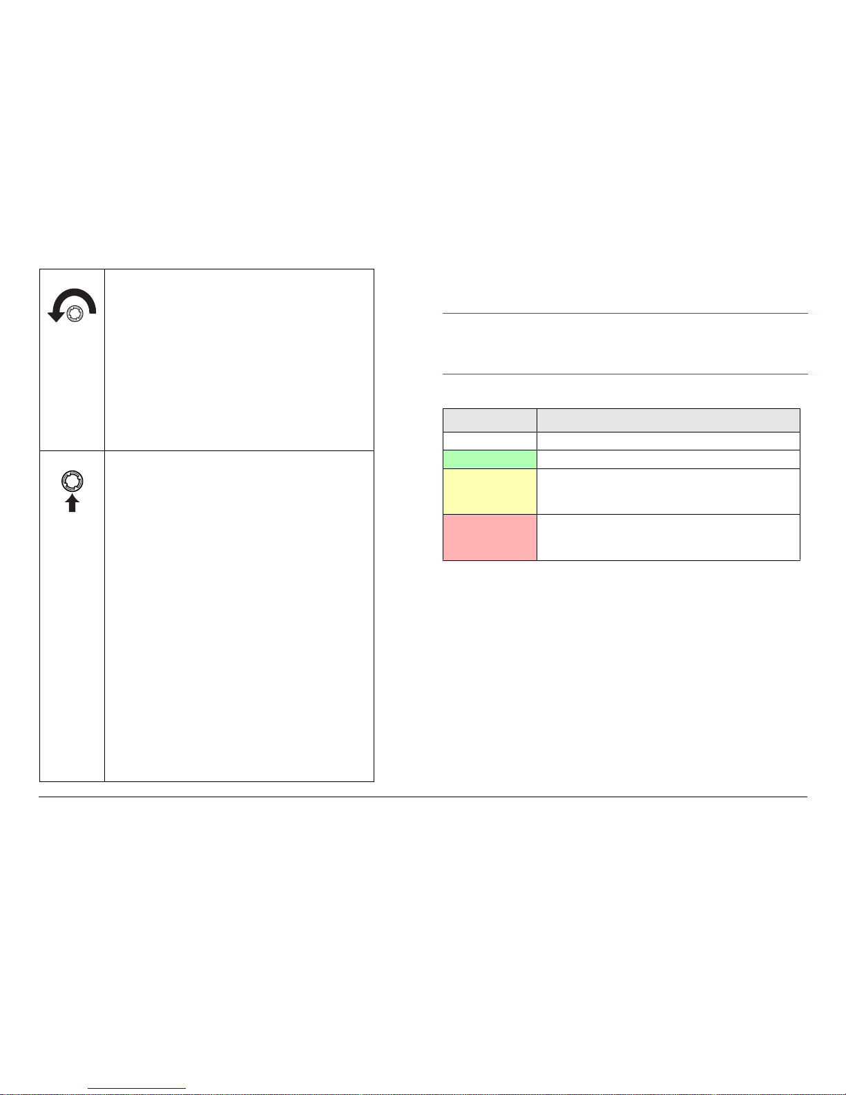
Control Switch Routine MDR-2 operating settings are
controlled by the front panel control switch. Turning the control
switch right (cw) or left (ccw) displays status and settings, and
pressing it in makes selections as described below:
Turning the control switch to the right (cw)
displays the Monitor options.
The Monitor options provide current status
of the MDR-2, including:
• Preset Number and Channel Frequency
• Modulation, Bandwidth, Forward Error
Correction, and Guard Interval
• Bit Error Rates for Channels 1 and 2
• Modulator Error Rates for Channels 1 and 2
• Signal to Noise Ratio for Channels 1 and 2
• COFDM Status (Lock or Unlock) for
Channels 1 and 2
• Transport Stream Status (Lock or Unlock)
• Video Output Setting (Composite Video or
SDI) and Video Data Status (Lock or Unlock)
• Audio A Data Status (Lock or Unlock) and
Audio Type (Analog/Digital, Stereo/Mono)
• Audio B Data Status (Lock or Unlock) and
Audio Type (Analog/Digital, Stereo/Mono)
• Color Bar Generator Setting (On or Off)
• System Errors.
Page 21
Routine Operation 3-3MDR-2 Operator’s Guide/Tech Ref Manual
Turning the control switch to the left (ccw)
displays the Command options.
The Command options allow control of the
MDR-2, including:
• Changing the Preset
• Setting the RF Channel
• Setting the RF Band
• Setting the COFDM Bandwidth
• Selecting DC on Coax on or off for MRC
Block Down Converters.
Pressing the control switch causes an
action to occur.
Command Options
• If the displayed setting is Chng Preset, Set
Channel, or Set OFDM BW, pressing the
control switch causes the displayed setting to
blink.
Turning the control switch cw or ccw then
displays the other options for that setting.
When the desired option is displayed,
pressing the control switch selects that
option.
• If the displayed setting is CH1/CH2 Power,
pressing the control switch selects the other
option for that setting.
The display will change back to the Main
screen and the setting is automatically saved.
Monitor Options
• Press the control switch to lock the display on
this screen. Data on display will continue to
update. Press the control switch again to
unlock the display.
Status LED Located above the PWR switch is a multi-color
status LED. The LED indications are as follows:
WARNING
A Major Alarm may also indicate a potential
safety hazard. Shut down the MDR-2
receiver and disconnect power.
PWR Switch The front panel PWR (power) switch controls
application of AC or DC power to the MDR-2.
DC ON COAX Switch The front panel DC ON COAX switch
allows you to power the MRC Block Down Converters from the
MDR-2 using DC superimposed on the coaxial cables between
the MDR-2 and the Block Down Converters.
To set the front panel DC ON COAX switch to superimpose DC
on coax, rotate the switch until the switch screw slot points to the
ON position. To disable DC power on coax, rotate the switch
until the switch screw slot points to the OFF position.
LED Color Meaning
----- Power is not on in the unit.
Green Power is on and no errors are detected.
Amber Minor Alarm - Power is on but some part
of the system reports an abnormal
condition that might impair performance.
Red Major Alarm - Power is on but there is a
failure or error that prevents normal
operation.
Page 22

Routine Operation 3-4MDR-2 Operator’s Guide/Tech Ref Manual
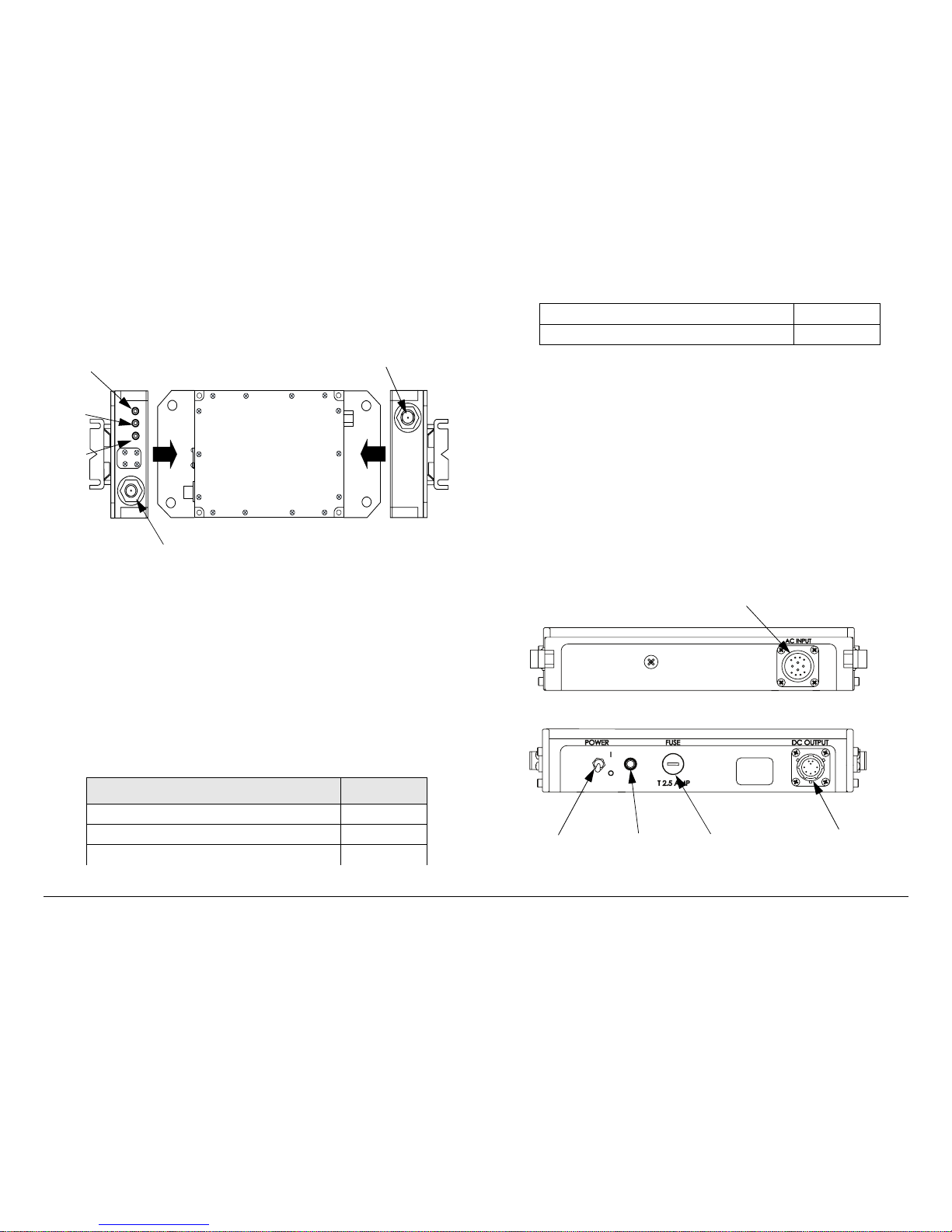
Figure 3-2: Rear Panel Controls, Indicators, and Connectors
POWER Connector The rear panel POWER connector of the
unit provides DC input power to the MDR-2.
SIGNAL OUT BNC Connector The SIGNAL OUT 75 ohm,
female, BNC connector provides composite video or SDI outputs
from the unit.
ASI MON BNC Connector The ASI MON 75 ohm, female, BNC
connector provides the ASI signal monitoring output from the
unit.
INPUT A and INPUT B TNC Connectors The INPUT A and
INPUT B 75 ohm, female, TNC connectors receive the UHF
signals from the two Block Down Converters and corresponding
antennas.
To power the Block Down Converters, +9 VDC is superimposed
on the coaxial cables from the MDR-2 INPUT A and INPUT B
connectors to the Block Down Converters.
INPUT A INPUT B
POWER
AUDIO
SIGNAL OUT ASI MON
GEN LOCK
POWER
Connector
SIGNAL OUT
Connector
ASI MON
Connector
INPUT A
Connector
INPUT B
Connector
AUDIO
Connector
AUDIO Connector The 10-pin, circular, male AUDIO connector
provides the Audio A and Audio B outputs from the unit.
3.2.2 Block Down Converter Indicators and
Connectors
Indicators and connectors contained on the MRC Block Down
Converters (BDC) are identified and described below. Topics
covered are as follows:
Each of the indicators and connectors are described in more
detail in the following paragraphs. Indicators and connectors
contained on the Block Down Converters are shown in Figure 3-
3 on page 3-5.
PWR LED The PWR (power) LED is on when power is applied
to the MDR-2 and DC on coax power is applied to the Block
Down Converter.
A LED The A LED is on whenever power is applied to the Block
Down Converter, indicating Band A is selected for operation.
(Only one band is currently available.)
B LED The B LED is not currently used.
Topic Page
PWR LED 3-4
A LED 3-4
B LED 3-4
IF OUTPUT Connector 3-5
RF INPUT Connector 3-5
Page 23
Routine Operation 3-5MDR-2 Operator’s Guide/Tech Ref Manual
Figure 3-3: Block Down Converter Indicators and
Connectors
IF OUTPUT Connector The 75 ohm, TNC, female, IF OUTPUT
connector provides the If output from the unit.
RF INPUT Connector The 50 ohm, type “N”, male, RF INPUT
connector provides the RF input from the antenna to the unit.
3.2.3 ACU Controls, Indicators, and Connectors
Controls, indicators, and connectors contained on the optional
ACU are identified and described below. Topics covered are as
follows:
Topic Page
AC INPUT Connector 3-5
POWER Switch 3-5
Power LED 3-6
RF INPUT
PWR
A
B
BAND A/B
IF OUTPUT
IF OUTPUT
Connector
RF INPUT
Connector
PWR
LED
A LED
B LED
Each of the controls, indicators, and connectors are described in
more detail in the following paragraphs. Controls, indicators, and
connectors contained on the ACU are shown in Figure 3-4.
AC INPUT Connector The AC INPUT connector mounted on
the rear panel of the unit provides external AC power to the unit.
POWER Switch The front panel POWER switch controls
application of DC power to the DC OUTPUT connector. When
the switch is set to I (on), DC power is present at the DC
OUTPUT connector. When set to 0 (off), no output DC power is
present at the DC OUTPUT connector.
Figure 3-4: ACU Controls, Indicators, and Connectors
DC OUTPUT Connector 3-6
FUSE 3-6
OUTPUT
OUTPUT
< >
< >
DC
DC
Rear View
Front View
AC INPUT
Connector
FUSE
POWER
Switch
DC OUTPUT
Connector
POWER
LED
Page 24
Routine Operation 3-6MDR-2 Operator’s Guide/Tech Ref Manual
Power LED The power LED is on when the POWER switch is
set to I (on), indicating DC power is available at the DC OUTPUT
connector. The indicator is off when the POWER switch is set to
0 (off).
DC OUTPUT Connector Depending upon the model of your
ACU, the DC OUTPUT connector mounted on the front panel of
the unit provides +15 VDC or +28 VDC to provide power to the
MDR-2 receiver system.
FUSE The fuse provides overload protection for AC input power.
3.3 Preparing for Operation
Each installation or deployment will have its own specific tasks
according to the application and the installed hardware.
3.3.1 Mobile Installation
For mobile applications such as aircraft or vehicle, the MDR-2 is
usually mounted in a bulkhead or compartment using an MRC
Fixed Mounting Bracket. See Figure 3-5. Mounting brackets
are available to mount from one to three units.
Figure 3-5: Fixed Mounting Bracket - Typical
The cabling is permanently installed and power comes from
aircraft or vehicle power.
3.3.2 Portable Deployment
For portable deployment situations, to mount an MDR-2 and its
fixed mounting bracket to an MRC tripod, MRC offers a Quick
Release Mount. See Figure 3-6. The Quick Release Mount is
attached to the bottom of the Universal Mounting Bracket.
Figure 3-6: Quick Release on Tripod - Typical
Quick Release
Mount
MRC Tripod
Mount
Dovetail Adapter
Plate (Machined)
Fixed Mounting
Bracket
Page 25
Routine Operation 3-7MDR-2 Operator’s Guide/Tech Ref Manual
Note
The versatility of the Quick Release Mount and a
mating Dovetail Adapter Plate allows the Dovetail
Adapter Plate to be attached to the bottom of the
Universal Mounting Bracket and the Quick Release
Mount to be attached to a non-MRC tripod, or vice
versa.
For optional methods of attaching your MDR-2 to a
non-MRC tripod, refer to the “Installation” Chapter
on page 6-1 (part of the Portable 2-Input Diversity
Receiver Technical Reference Manual only).
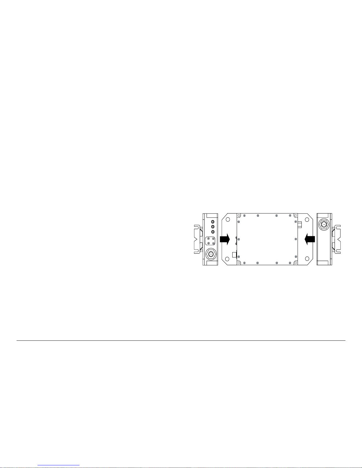
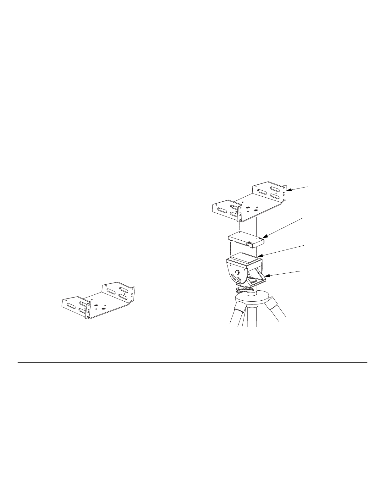
For portable deployment situations where you are mounting the
MDR-2 to another type of tripod that doesn’t directly accept the
MRC Quick Release Mount, consult with MRC or your tripod
manufacturer. MRC has Dovetail Adapter Plates that will convert
some types of tripods to accept the MRC Quick Release Mount.
For portable applications where the MDR-2 system will be
moved from place to place and set up each time, the MDR-2
must be mounted in an MRC Universal Mounting Bracket. The
Universal Mounting Bracket is attached to the Quick Release for
easy mounting on an MRC tripod. See Figure 3-7.
Universal Mounting Brackets are required for each unit in the
MDR-2 system, i.e., MDR-2 and an optional ACU. For
applications using multiple units such as an MDR-2 and an ACU,
a Mounting Plate is also used to provide additional stiffness.
See Figure 3-7. The Mounting Plate typically remains attached
between the Universal Mounting Bracket and the Quick Release
Mount.
The cabling between the MDR-2 and the optional ACU is
typically left in place. The power, antenna, and audio/video
connections are usually removed at the end of each deployment.
Figure 3-7: Universal Mounting Bracket on Tripod - Typical
Note
The procedures and illustrations contained in the
following paragraph are typical, reflecting use of an
MRC tripod.
Mounting to the Tripod Following are general steps required
to mount an MDR-2 system to an MRC Tripod. These steps
assume the Quick Release Mount is already mounted on the
Universal Mounting Bracket and the MDR-2 system is
assembled onto its Universal Mounting Bracket.
Universal Mounting
Bracket
Mounting Plate (Required
for Multi-Unit Applications
Only)
Quick Release
Mount
MRC Tripod Mount
(Typical)
Dovetail Adapter
Plate (Machined)
Page 26

Routine Operation 3-8MDR-2 Operator’s Guide/Tech Ref Manual
If the MDR-2 system includes an ACU, the procedure assumes
the ACU is installed in its Universal Mounting Bracket and the
Mounting Plate and Quick Release are completely assembled.
The antennas must also be installed on their respective antenna
mounts.
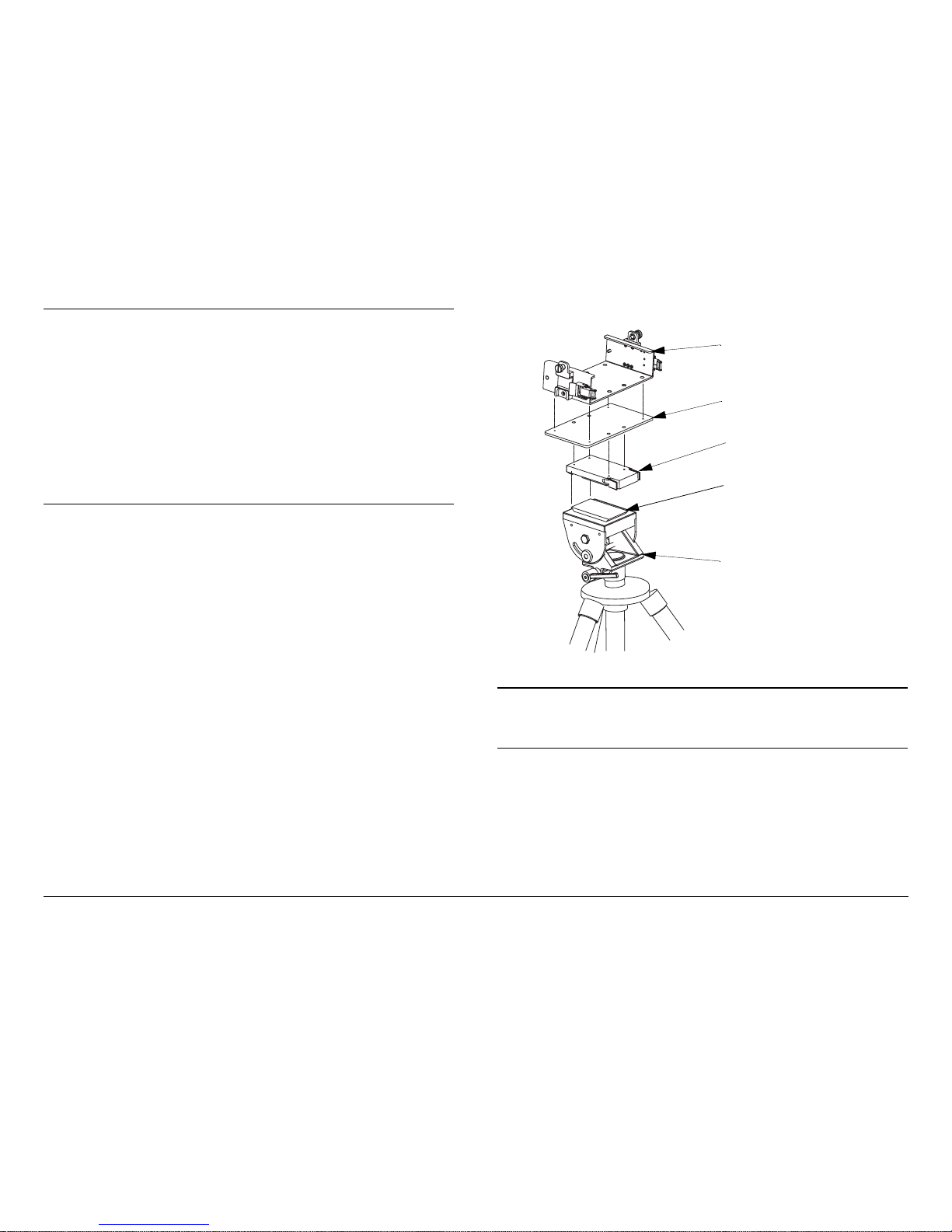
1. Attach the MDR-2 system to the tripod using the Quick
Release Mount, as shown in Figure 3-8 and Figure 3-9
on page 3-9.
Figure 3-8: Attaching Quick Release to MRC Tripod - Typical
Note
Distance between antennas and cable types and
lengths are critical when installing the antennas.
Refer to the “Installation” Chapter on page 6-1
(part of the Portable 2-Input Diversity Receiver
Technical Reference Manual only) for information
on installation of the two antennas.
Quick
Release
Mount
Tripod
Mount
Dovetail
Adapter Plate
2. Attach the Block Down Converters to the MDR-2 using
coaxial cables from the MDR-2 INPUT A and INPUT B
connectors to the two Block Down Converter IF
OUTPUT connectors.
Install the antennas per the “Installation” Chapter on
page 6-1 (part of the Portable 2-Input Diversity
Receiver Technical Reference Manual only).
Attach the Block Down Converters to the antennas,
either directly, or by using coaxial cables between the
antennas and the Block Down Converter RF INPUT
connectors.
If you are unsure of the connections, refer to the
“Installation” Chapter on page 6-1 (part of the Portable
2-Input Diversity Receiver Technical Reference
Manual only).
Page 27

Routine Operation 3-9MDR-2 Operator’s Guide/Tech Ref Manual
Figure 3-9: Complete MRC Tripod Installation - Typical
3. Connect the MDR-2 to DC power of the correct
voltage and polarity.
If you’re using a STRATA ACU, connect the AC input
to AC power and connect the DC output to the MDR-2.
If you are unsure of the power requirements or the
connections, refer to the “Installation” Chapter on
Universal
Mounting
Brackets
ACU
MDR-2
Quick
Release
Mount
Tripod
Mounting
Plate
page 6-1 (part of the Portable 2-Input Diversity
Receiver Technical Reference Manual only).
4. Connect the MDR-2 outputs to your audio and video
equipment.
3.3.3 Powering the MDR-2
The procedures required to power up and power down the MDR2 are contained in the following steps.
Power Up
CAUTION
To avoid possible equipment damage, turn
off DC power on coax before connecting
any test equipment.
1. Turn the front panel DC ON COAX switch until the
switch screw slot points to ON.
2. Verify the power cable is properly connected to the
MDR-2 rear panel power connector.
3. Verify all front and rear panel cables and connectors
have been properly connected.
If you are unsure of the connections, refer to the
“Installation” Chapter on page 6-1 (part of the Portable
2-Input Diversity Receiver Technical Reference
Manual only).
4. Connect the power cable to the power source.
If you are unsure of the power requirements or the
connections, refer to the “Installation” Chapter on
page 6-1 (Part of the Portable 2-Input Diversity
Receiver Technical Reference Manual only).
Page 28

Routine Operation 3-10MDR-2 Operator’s Guide/Tech Ref Manual
5. Verify the power source is turned on.
6. Set the front panel PWR switch to on ( I ).
7. The normal power-up sequence is as follows:
- The status LED above the PWR switch should
illuminate and should change colors from red, to
green, to amber, and finally to green and should
remain green.
- The alphanumeric display should light up and quickly
display the radio version and then the Main screen.
- Some typical screens are shown in Figure 3-10.
- The MDR-2 will typically power up using the last
settings in use when power was turned off.
- If the MDR-2 does not power up normally, refer to the
“Troubleshooting” Chapter on page 4-1.
Figure 3-10: MDR-2 Power Up Screen - Typical
8. Rotate the front panel control switch ccw until the CH1
Power option is displayed.
9. Press the control switch to select Power On, as
required. Observe the Main screen is displayed.
10. Rotate the control switch ccw until the CH2 Power
option is displayed.
MDR-2
V X.X.X
-99.9 dBm LQ0
-99.9 dBm LQ0
Radio Version
Main Screen
11. Press the control switch to select Power On, as
required. Observe the Main screen is displayed.
Power Down
1. Set the PWR switch to off ( 0 ).
2. Set the power source power to off.
3.4 Using the Display Screens
As you use the MDR-2, you will interact extensively with the
screens displayed on the alphanumeric display. Following are
some points to make this easier.
Main Screen The Main screen is your starting point for
navigating through the Monitor and Control screens. The Main
screen provides the current values of the Preset selected and
the selected Preset output power level.
When the MDR-2 completes its power-up sequence, the Main
screen will be displayed. A typical Main screen (with no detected
input) is shown in Figure 3-11.
Figure 3-11: Main Screen - Typical
Accessing the Main Screen You can access the Main screen
at any time by scrolling to the end of the screens you are viewing
(either Monitor or Control). Your next click of the control switch
will bring up the Main screen.
-99.9 dBm LQ0
-99.9 dBm LQ0
Channel 1
Stat us
Channel 2
Stat us
Page 29

Routine Operation 3-11MDR-2 Operator’s Guide/Tech Ref Manual
Accessing the Monitor Screen You can access the Monitor
screen at any time by turning the control switch clockwise (cw).
Accessing the Control Screen You can access the Control
screen at any time by turning the control switch counterclockwise (ccw).
Default to Main Screen If you do not turn or press the control
switch within a period of approximately 7 seconds, the display
will default to the Main screen.
If you turn the control switch within those 7 seconds, you will
continue scrolling within that set of screens (Monitor or Control).
3.5 Monitoring Options
MDR-2 monitoring options displayed on the Monitor screens are
accessed by rotating the control switch ccw. Monitor screen
options that can be viewed on the front panel display fall under
three categories, as follows:
•Detected:
- Values that are automatically sensed by the MDR-2 to
match transmitter settings
•Settings:
- Values that are configured in the MDR-2 and must be
manually set to match transmitter settings either via
the front panel control switch or via the MDR
Configuration Utility software
•Derived:
- Values that are calculated by the MDR-2 based upon
the characteristics of the incoming signal
Monitor screen options that can be viewed on the front panel are
as follows:
•Detected:
- Modulation, Bandwidth, Forward Error Correction
(FEC), and Guard Interval (GI)
- COFDM Status (Locked or unlocked) for Channels 1
and 2
- Transport Stream Status (Locked or Unlocked)
- Audio A Data Status (Locked or Unlocked) and Audio
Type (Analog/Digital, Stereo/Mono)
- Audio B Data Status (Locked or Unlocked) and Audio
Type (Analog/Digital, Stereo/Mono)
- System Errors
• Settings:
- Preset Number and Channel Frequency
- Video Output Setting (Composite Video or SDI) and
Video Data Locked Status (Yes or No)
- Color Bar Generator Setting (On or Off)
•Derived:
- Received Carrier Level (RCL)
- Link Quality (LQ)
- Bit Error Rates for Channels 1 and 2
- Modulator Error Rates for Channels 1 and 2
- Signal to Noise Ratio for Channels 1 and 2
Once the MDR-2 is set up and powered up, you will be able to
check its configuration and monitor its operation by rotating the
control switch cw. No setting changes may be made to the
Monitoring screens using the control switch.
Refer to Figure 3-12 on page 3-12 for the Monitor Menu Map.
Page 30

Routine Operation 3-12MDR-2 Operator’s Guide/Tech Ref Manual
Figure 3-12: Monitor Menu Map
-45.0 dBm LQ6
-40.0 dBm LQ6
MER 20.5 dB
MER 20.5 dB
OFDM1 Lock
OFDM2 Lock
Preset #1
2016.500MHz
SNR 20.5 dB
SNR 20.5 dB
Trans Lock
COQPSK Auto
FE1/2 GI1/8
BER 2.0E-7
BER 2.0E-7
Video Out CV
Lock
Aud A Lock
Analog Mono
Aud B Lock
Analog Mono
ClrBar OFF
No Errors
3.5.1 Monitoring Link Quality (LQ)
One of the key differences between analog and digital
transmission is how the receiving system reacts to degrading
signal quality.
Digital Systems In a digital system, degrading signal quality
initially has no effect on the video and audio. Error-correction
algorithms correct the errors, and video remains clean.
As the signal quality continues to deteriorate, it reaches a point
when the algorithms cannot correct all the errors. As the errors
get worse, the MPEG decoder will be unable to construct an
image, and video will suddenly be lost.
Operators sometimes refer to this sudden loss of video, with little
or no apparent warning, as “falling off a cliff”.
Link Quality MRC has developed the Link Quality indicator to
give you the “early warning” of an analog system. Link Quality
monitors several key parameters and uses proprietary
algorithms to derive one simple indication of digital signal quality.
The Link Quality algorithms report one Link Quality (LQ) result,
scaled from 0 to 9 as shown in Table 3-1 on page 3-13.
For more information on Link Quality, refer to the “Link Quality”
Appendix on page C-1.
Page 31

Routine Operation 3-13MDR-2 Operator’s Guide/Tech Ref Manual
Table 3-1: Link Quality Levels
LQ
Reading
Link Quality Description
9 Excellent Link Quality - COFDM link is very robust
with ample ability to correct for degradation.
8 Very Good Link Quality - COFDM link is robust for
the given environment.
7Standard Link Quality - COFDM link is acceptable
for current environment.
6Average Link Quality - COFDM link is average -
might improve or worsen.
5 Below Average Link Quality - COFDM link is
marginal, not dependable.
3, 4 Poor Link Quality - COFDM link is unstable -
quality is intermittent and unpredictable.
1, 2 Unsatisfactory Link Quality - COFDM link is not
locked.
0 No signal detected.
Checking Link Quality To check Link Quality, perform the
following steps:
Blinking LQ If the LQ reading is blinking on the screen, this
indicates that the LQ has dropped to 4 or below, sometime within
the last 2 minutes. The blinking will automatically stop when 2
minutes have elapsed with an LQ maintained above 4.
3.5.2 LQ Action Levels
Table 3-2 on page 3-14 describes the actions we recommend at
various LQ levels. These are a good initial guide. You should
adjust what you do based on your experience.
Be sure MDR-2 is connected and
powered.
See ”Powering the MDR-
2” on page 3-9.
Link Quality is displayed on the Main
screen.
To lock this screen on the display, perform the
following:
Press the control switch to lock the
display on this screen. Data on
display will continue to update.
To allow the display to show other screens,
perform the following:
Press the control switch to unlock the
display.
Display changes back to the Main
screen.
-43.2 dBm LQ6
-43.2 dBm LQ6
Page 32

Routine Operation 3-14MDR-2 Operator’s Guide/Tech Ref Manual
3.5.3 What Actions to Take
To improve the Link Quality, we suggest the following general
sequence of actions. You should develop your own action plan
so you’re prepared in case LQ begins to fall.
1. Optimize RCL.
- No signal: Check channel and frequency - be sure
they match the transmitted signal.
- If RCL is -70 dBm or lower, the signal is weak.
Reposition transmit and receive antennas, or increase
transmit power if possible.
Table 3-2: Actions at Link Quality Levels
LQ
Reading
LInk Quality
Description
Recommended Action
9 Excellent Link
Quality
None required.
Most transmissions are made
with LQ of about 7.
8 Very Good Link
Quality
7 Standard Link
Quality
6Average Link
Quality
Begin to take action.
5 Below Average
Link Quality
Rapidly take additional
actions.
3, 4 Poor Link Quality Immediately take all available
actions.
1, 2 Unsatisfactory
Link Quality
0 No signal
detected.
- An RCL of -40 to -30 dBm is ideal.
- RCL should be less than -25 dBm. Signals stronger
than this can overload the MDR-2 and actually make
the demodulated signal quality worse.
2. Optimize SNR
- If RCL is OK, but SNR is low (13 -15 dB or less), there
may be electrical equipment (or other transmitters) in
the immediate area creating noise.
- Try other channels and offsets to avoid other
transmitters.
- Isolate noise sources by shutting down other
equipment.
3. Optimize BER
- No signal: Check the COFDM BW setting to be sure
it matches the incoming signal.
- Change transmit settings to make the link more robust.
You will achieve a lower Data Transfer Rate as you do
so. See Table 3-3 on page 3-15.
Note - Factory default settings are highlighted in bold
font.
- The receiver will automatically adjust for the new
settings.
Note - BW must be manually set to match the
transmitter.
Page 33

Routine Operation 3-15MDR-2 Operator’s Guide/Tech Ref Manual
3.5.4 Monitoring Bit Error Ratio (BER)
One useful indicator of digital signal quality is the Bit Error Ratio
(BER). The BER is calculated as:
The way the MDR-2 displays BER information provides a good
indication of the unit’s overall performance.
Channel 2 (the bottom row on the display) displays the BER
value before any error correction is applied and before any
diversity algorithms are applied, therefore giving you the
performance of a single channel receiver.
Channel 1 (the top row on the display) provides the actual BER
value after the diversity algorithms and the error correction are
Table 3-3: Setting Changes to Improve Link Quality
Link Capability
Least
Robust
Most
Robust
Modulation 64 QAM 16QAM QPSK
FEC 7/8 5/6 3/4 2/3
1/2
GI 1/32 1/16
1/8 1/4
BW
8 MHz 7 MHz 6 MHz
Note - Receiver BW must be manually set to match
transmitter.
Highest Lowest
Data Transfer Rate
Factory Default Settings are highlighted in bold font.
Error Bits Detected / Total bits received
applied. You are then able to monitor both single channel and
dual channel receiver performance at the same time.
These would appear on the BER Monitor screen as:
Using BER BER is one of the key components in MRC’s Link
Quality indicator. It also can be used on its own to help alert the
operator to deteriorating signal quality.
As signal quality degrades, the FEC algorithms will be able to
correct any errors, and the Post-Viterbi BER will be maintained
at 0. Video and audio will be undisturbed.
As the signal continues to degrade, at some point the FEC
algorithms will reach the limit of errors they can correct. The
uncorrected errors will then appear in the Post-Viterbi BER.
These Post-Viterbi errors are a warning sign, even though the
video may still be acceptable.
If the Post-Viterbi BER becomes too large, the MPEG decoder
will be unable to make sense of the data, and video will be lost.
Monitoring the BER screen will help you be aware of this signal
degradation so you can take corrective action.
To access the BER Monitor screen, perform the following steps:
Be sure MDR-2 is connected and powered.
See ”Powering the MDR-2” on page 3-
9.
Start at the Main screen.
BER 0.0E-7
BER 0.0E-7
-43.2 dBm LQ6
-43.2 dBm LQ6
Page 34

Routine Operation 3-16MDR-2 Operator’s Guide/Tech Ref Manual
3.5.5 Monitoring Signal-to-Noise Ratio (SNR)
Another useful indicator of digital signal quality is the Signal-toNoise Ratio (SNR). SNR is a ratio expressed in dB, and
calculated as:
To access the SNR Monitor screen, perform the following steps:
Turn the control switch clockwise until the
display shows the BER Monitor screen. It
will be similar to this:
To lock this screen on the display, perform the following:
Press the control switch to lock the display
on this screen. Data on display will
continue to update.
To allow the screen to default normally to the Main
screen, perform the following:
Press the control switch to unlock the
display.
Display changes back to the Main screen.
BER 0.0E-7
BER 0.0E-7
Overall Signal Strength / Detected Noise
Be sure the MDR-2 is connected and
powered.
See ”Powering the MDR-
2” on page 3-9.
Start at the Main screen.
Turn the control switch clockwise until
the display shows the SNR Monitor
screen. It will be similar to this:
To lock this screen on the display, perform the
following:
Press the control switch to lock the
display on this screen. Data on
display will continue to update.
To allow the screen to default normally to the Main
screen, perform the following:
Press the control switch to unlock the
display.
Display changes back to the Main
screen.
-43.2 dBm LQ6
-43.2 dBm LQ6
SNR 20.78 dB
SNR 20.68 dB
Page 35

Routine Operation 3-17MDR-2 Operator’s Guide/Tech Ref Manual
3.6 Control Operations
This section describes how to configure your MDR-2 using the
front panel control switch. Turning the control switch ccw
controls MDR-2 functions including changing Presets, setting
channels, selecting high or low band operation, and selecting
bandwidth. DC on coax power may be turned on or off, as
required, to power the MRC Block Down Converters.
Here are the tasks described:
Refer to Figure 3-13 on page 3-18 for the Command Menu Map.
See ”Front Panel vs. MDR Configuration Utility Settings” on
page 3-21 for a summary of settings that can be changed using
the front panel control switch and those that are made using the
MDR Configuration Utility software.
Topic Page
Changing a Preset 3-17
Setting a Channel and
Offset
3-19
Set OFDM Bandwidth 3-20
Select DC On Coax 3-20
3.6.1 Changing a Preset
The MDR-2 is designed to enable you to control operating
settings through Presets stored in the MDR-2. The MDR-2 is
shipped with factory Presets and can be customized for the user.
Your MDR-2 can be pre-configured with up to 9 Presets. Each
Preset contains most of the operating settings needed to control
the unit. System Presets can only be defined and changed using
the MDR Configuration Utility software. Presets cannot be
defined or changed from the MDR-2 front panel.
Page 36

Routine Operation 3-18MDR-2 Operator’s Guide/Tech Ref Manual
Figure 3-13: Command Menu Map
-45.0 dBm LQ6
-40.0 dBm LQ6
Chng Preset
Preset #3
Select Preset 1
thru 9
Set Channel
Ch 2
Select Channel 1
thru 10 (up to
22 max.)
Set RF Band
Low Band
Set OFDM BW
Auto
Select Auto, 6,
7, or 8 MHz
CH1 Power
Power On
Select Power On
or Power Off
CH2 Power
Power On
Select Power On
or Power Off
Factory set for
“Low Band” or
“High Band”
Page 37

Routine Operation 3-19MDR-2 Operator’s Guide/Tech Ref Manual
Notes
When a Preset is changed, the channel does not
change.
When a channel is changed, the Preset does not
change.
To change Presets, perform the following steps:
1. Verify the MDR-2 is connected and powered up.
2. Observe the Main screen is displayed. See Figure 3-
14.
Figure 3-14: Main Screen - Typical
3. Turn the control switch ccw until the display reads
Chng Preset.
4. Press the control switch to select Chng Preset. See
Figure 3-15.
Figure 3-15: Change Preset Screen - Typical
5. Observe the current Preset setting begins to blink.
6. Turn the control switch cw or ccw until the desired
Preset is displayed.
7. Press the control switch once to select that Preset.
8. Observe the display changes back to the Main screen
after a short delay.
-45.5 dBm LQ6
-40.5 dBm LQ6
Chng Preset
Preset 3
Blinking
3.6.2 Setting a Channel and Offset
The MDR-2 channel and offset can be selected from the front
panel and can be configured for operation on 1 to 10 (14 or 22)
channels. For more information, see the “Channels and
Frequencies” Appendix on page A-1.
The frequencies assigned to each channel must be configured
using the MDR Configuration Utility software. The frequencies
cannot be changed from the MDR-2 front panel.
Notes
When a channel is changed, the Preset does not
change.
When a Preset is changed, the channel does not
change.
To change the channel frequency and offset, perform the
following steps:
1. Verify the MDR-2 is connected and powered up.
2. Observe the Main screen is displayed. See Figure 3-
16.
Figure 3-16: Main Screen - Typical
3. Turn the control switch ccw until the display reads Set
Channel.
4. Press the control switch to select Set Channel. See
Figure 3-17 on page 3-20.
-45.5 dBm LQ6
-40.5 dBm LQ6
Page 38

Routine Operation 3-20MDR-2 Operator’s Guide/Tech Ref Manual
Figure 3-17: Set Channel - Typical
5. Observe the current Channel setting begins to blink.
6. Turn the control switch cw or ccw until the desired
channel and offset is displayed.
7. Press the control switch once to select the required
channel and offset.
8. Observe the display changes back to the Main screen
after a short delay.
3.6.3 Set OFDM Bandwidth
The procedure required to select the OFDM bandwidth is
contained in the following steps.
1. Verify the MDR-2 is connected and powered up.
2. Observe the Main screen is displayed. See Figure 3-
18.
Figure 3-18: Main Screen - Typical
3. Turn the control switch ccw until the display reads Set
OFDM BW.
4. Press the control switch to select Set OFDM BW. See
Figure 3-19.
Set Channel
Ch +2
-45.5 dBm LQ6
-40.5 dBm LQ6
Figure 3-19: Set OFDM Bandwidth - Typical
5. Observe the current bandwidth setting begins to blink.
Note
In the following step, the Auto option only operates
on 6 MHz or 8 MHz input signals.
6. Turn the control switch cw or ccw to select 6 MHz, 7
MHz, 8 MHz, or Auto, as required.
7. Press the control switch once to select the bandwidth.
8. Observe the display changes back to the Main screen
after a short delay.
3.6.4 Select DC On Coax
The procedure required to apply DC on coax to power the Block
Down Converters or to shut off DC on coax is contained in the
following steps.
This procedure must be performed on both channel 1 and
channel 2. DC on coax power must be on or off for both
channels.
CAUTION
To avoid possible equipment damage, turn
off DC power on coax before connecting
any test equipment.
To prevent damage to any connected test equipment, there is a
two-stage process to turn on DC power to the coax cables. To
enable DC on coax, both of the following must be performed:
Set OFDM BW
7 MHz
Page 39

Routine Operation 3-21MDR-2 Operator’s Guide/Tech Ref Manual
• The front panel DC ON COAX switch must be set to the
ON position
• The system must be configured to have DC on coax
power by selecting both the CH1 Power and CH2 Power
Power On options on the Control screen.
1. Verify the MDR-2 is connected and powered up.
2. Observe the Main screen is displayed. See Figure 3-
20.
Figure 3-20: Main Screen - Typical
3. Turn the control switch ccw until the display reads CH1
Power. See Figure 3-21.
Figure 3-21: Change DC on Coax Power - Typical)
4. Press the control switch to select Power On or Power
Off, as required.
5. Observe the Main screen is displayed.
6. Turn the control switch ccw until the display reads CH2
Power. See Figure 3-22.
-45.5 dBm LQ6
-40.5 dBm LQ6
CH1 Power
Power Off
Figure 3-22: Change DC on Coax Power - Typical
7. Press the control switch to select Power On or Power
Off, as required.
8. Observe the Main screen is displayed.
3.7 Front Panel vs. MDR
Configuration Utility Settings
The design of the MDR-2 and MDR Configuration Utility software
makes commonly available settings accessible from the MDR-2
front panel switches and alphanumeric display and more
advanced settings accessible through the MDR Configuration
Utility software.
A summary of settings that can be controlled from the front panel
and by the MDR Configuration Utility software is shown in Table
3-4.
Table 3-4: Front Panel vs. Configuration Utility Setting
Parameter
Available
Settings
Set
Using
Control
Switch
Set Using
Configuration
Utility
Radio
Preset in use 1, 2,... 9
✔ ✔
Channel • 1 thru 10 (14
or 22)
✔ ✔
Offset • -, 0, +, ++
✔ ✔
CH2 Power
Power Off
Page 40

Routine Operation 3-22MDR-2 Operator’s Guide/Tech Ref Manual
Channel and
Offset
Frequencies
Depends upon
band
✔
RF Band in
Use
• Low Band
• High Band
FactoryConfigured Only
Frequencies
Assigned to
High and Low
Bands
Depends upon
band
FactoryConfigured Only
CH 1 Power
(DC on
Signal Input)
• Power On
✔ ✔
• Power Off
✔ ✔
CH 2 Power
(DC on
Signal Input)
• Power On
✔ ✔
• Power Off
✔ ✔
Presets
Preset Name Any 12
alphanumeric
characters
✔
Operation
Mode
• MPEG CV
Out
✔
• SDI Output
✔
Bandwidth • 6 MHz
✔ ✔
•7 MHz
✔ ✔
•8 MHz
✔ ✔
•Auto
✔ ✔
Table 3-4: Front Panel vs. Configuration Utility Setting
Parameter
Available
Settings
Set
Using
Control
Switch
Set Using
Configuration
Utility
BISS
Encryption
•OFF ✔
•BISS-1
✔
•BISS-E
✔
PID Settings • PCR PID
✔
•DATA PID
✔
•Video PID
✔
• Audio PID A/B
✔
NTSC
Pedestal
•On
✔
•Off
✔
Color Bars • ON
✔
•OFF
✔
Audio Output • AES/EBU
✔
• Analog
✔
Audio A
Output Level
• Value limits
are 0.0 to 6.0
dB in 0.1 dB
increments.
✔
Audio B
Output Level
• Value limits
are 0.0 to 6.0
dB in 0.1 dB
increments.
✔
Table 3-4: Front Panel vs. Configuration Utility Setting
Parameter
Available
Settings
Set
Using
Control
Switch
Set Using
Configuration
Utility
Page 41

Troubleshooting 4-1MDR-2 Operator’s Guide/Tech Ref Manual
Troubleshooting
4.1 Chapter Overview
This chapter describes how to troubleshoot your MDR-2 Portable
2-Input Diversity Receiver system.
Here are the topics covered:
Topic Page
Status LED
4-1
Display Messages
4-2
Error Codes
4-3
Operational Problems
4-6
4.2 Status LED
Above the MDR-2 front panel PWR switch is a multi-color status
LED that provides unit status indications. The status LED
indications are listed in Table 4-1.
WARNING
A Major Alarm may also indicate a
potential safety hazard. Shut down the
MDR-2 and disconnect power.
Table 4-1: Status LED Indications
LED
Color
Meaning Suggested Action
----- Power is not on in the unit. Turn on power.
Green Power is on and no errors
are detected.
None.
Amber Minor Alarm - Power is on
but some part of the system
reports an abnormal
condition that requires
attention. Condition might
impair performance.
Check Monitor Screens
for error messages or
Error Codes.
Troubleshoot using
tables in this chapter.
Red Major Alarm - Power is on
but there is a serious failure
or error that will prevent
normal operation. The
internal processors are not
running.
Turn off unit and
disconnect power.
Call MRC Technical
Support.
Page 42

Troubleshooting 4-2MDR-2 Operator’s Guide/Tech Ref Manual
4.3 Display Messages
One of the ways the MDR-2 will alert you to problems is by error
messages on the MDR-2 front panel displays. These are
displayed on the Monitor Screens.
.
Table 4-2: Display Messages
Message Meaning Suggested Operator Action Suggested Technical Staff Action
Not On Chnl Channel frequencies
defined in the Channel
Plan for that band are not
being recognized.
Check settings of MDR-2 using front panel
display. Verify the correct channel is
selected and the frequency set for that
channel is correct.
• Use MDR-2 Configuration Utility
software to check settings. Check the
Channel Plan to be sure it is correct.
Verify Channel Plan matches the
transmitter settings.
• If message persists even when
operating on a frequency that matches
the channel plan, unit may have
suffered internal failure. Call MRC
Technical Support.
COFDM UNLOCK,
TRANS UNLOCK,
VIDEO UNLOCK, or
AUDIO UNLOCK
The MDR-2 is unable to
lock to the incoming signal.
• Check cable connection between
antenna and MDR-2 .
• Check for correct operation mode.
• Check Error code screen for errors.
• Check settings of MDR-2. Verify
settings match the transmitter,
specifically frequency and COFDM
bandwidth.
• Take actions to optimize RCL, SNR,
MER, and BER.
• Use MDR-2 Configuration Utility
software to check settings.
• If message persists, unit may have
suffered internal failure. Call MRC
Technical Support.
See Table 4-2 for descriptions of the messages and what to do
when they appear.
Page 43

Troubleshooting 4-3MDR-2 Operator’s Guide/Tech Ref Manual
4.4 Error Codes
The MDR-2 has a library of diagnostic error codes to help you
pinpoint any problems.
These error codes:
• Are displayed on the front panel display, on the Error
Code Screen
• Are reported and displayed by the MDR Configuration
Utility software, using the Monitor function on the Main
page
• Cause the status LED to glow amber, alerting you to
investigate the problem
The Error Codes are formatted into 2 groups of characters, as
shown in Figure 4-1.
Figure 4-1: Error Code Format
E020 4C
Primary Error Code
Identifies error
condition.
See ”Error Status”.
Error Status
Depends on error code.
See ”Primary Error Code”.
Unit ID
Identifies unit reporting
the error. In this case,
C = MDR-2
4.4.1 Error Status
The significance of the Error Status digit depends on what
Primary Error Code is being reported. See Table 4-3.
4.4.2 Primary Error Code
The first group of characters is the Primary Error Code. In most
cases this portion of the Error Code will uniquely identify the
problem.
See Table 4-4 on page 4-4 for descriptions of the error codes
and what to do when they appear.
Table 4-3: Error Status Digit
Status Digit Meaning
Status Error (Error Codes E120 - E122)
8 There is an error.
Parameter Error (Error Codes E1F1 - E1FA)
4 Value is too low.
8 Value is too high.
Page 44

Troubleshooting 4-4MDR-2 Operator’s Guide/Tech Ref Manual
Table 4-4: Primary Error Codes
Error
Code
Meaning Suggested Operator Action Suggested Technical Staff Action
Status Errors
(Some part of System is reporting an abnormal condition.)
E120 MPEG Transport Stream
Lock Alarm
• Check to ensure transmitter is
operating. If not transmitting, this
alarm is normal as there is no signal to
lock on to.
• Check connections between MDR-2,
Block Down Converters, and
antennas.
• Check settings of MDR using Control
and Monitor screens. The settings
must match transmitter settings.
• Take actions to optimize RCL, SNR,
MER, and BER.
• Contact technical staff.
• Use the MDR Configuration Utility software to check
settings. make sure all settings match transmitter
settings.
• Use the MDR Configuration Utility software to reprogram all radio settings.
• If problem persists, possible hardware failure has
occurred. Call MRC Technical Support.
E121 MPEG Video Lock Alarm
E122 MPEG PCR Lock Alarm
Parameter Errors
(Some internal parameter is outside of allowable limits.)
E1F1 MDR 5.5 Volt Line Error • Check for error codes E159 thru
E15B. Correct power problem
• Make certain all power cables are
properly connected.
• Contact technical staff.
If errors persist with correct power connected, possible
hardware failure has occurred. Call MRC Technical
Support.
E1F1 MDR +12 Volt Line Error
E1F3 MDR -12 Volt Line Error
Page 45

Troubleshooting 4-5MDR-2 Operator’s Guide/Tech Ref Manual
E1F4 MDR Temperature Error • Check MDR-2 to make sure it is not
too close to sources of heat. Relocate
unit if necessary.
• Verify MDR-2 has sufficient room
around it for air circulation. Move
objects away that are preventing
sufficient air flow.
• Contact technical staff.
If errors persist with proper location and airflow and
correct power is connected, possible hardware failure
has occurred. Call MRC Technical Support.
E1F8 MDR Circular Connector
Current Error
• Verify all power cables are connected
properly and are not damaged.
• Contact technical staff.
If errors persist with correct power connected, possible
hardware failure has occurred. Call MRC Technical
Support.
E1F9 MDR Circular Connector
Voltage Error
E1FA MDR Circular Connector
Power Error
Table 4-4: Primary Error Codes
Error
Code
Meaning Suggested Operator Action Suggested Technical Staff Action
Page 46

Troubleshooting 4-6MDR-2 Operator’s Guide/Tech Ref Manual
4.5 Operational Problems
Information provided on the following pages will assist you in
troubleshooting problems that arise in the operation of your
MDR-2 .
Table 4-5: Video Problems
Problem Possible Cause Suggested Operator Action Suggested Technical Staff Action
No Video Problem with video source
and cabling
Check video source and cabling • Check video source and cabling.
• Use the Color Bar generator function of the
MDR-2 for problems on the receiving end.
Turn on Color Bar option using MDR
Configuration Utility on the MPEG page.
Channel and frequency
settings of MDR-2 do not
match settings of
transmitter
Check settings of MDR-2 using
front panel Monitor and Control
screens. Channel, offset, and
frequency must match the
transmitter.
Use MDR Configuration Utility to check settings.
Verify all settings match the transmitter settings.
COFDM not locked Check COFDM Monitor screen. If
not locked, check COFDM
bandwidth setting. Bandwidth
must match with incoming signal.
Use MDR Configuration Utility to check
bandwidth settings. Verify all bandwidth settings
match the transmitter settings.
Video configuration
incorrect
Check video settings using
Monitor and Control screens.
Settings must match transmitter
settings.
Use MDR Configuration Utility to check video
settings. Verify all video settings match the
transmitter settings.
For video problems, see Table 4-5; for audio problems, see
Table 4-6 on page 4-8; and for general system problems, see
Table 4-7 on page 4-9.
Page 47

Troubleshooting 4-7MDR-2 Operator’s Guide/Tech Ref Manual
Poor Video Quality Low quality due to
interference or weak signal
Take actions to boost RCL,
improve SNR, and improve BER
and MER.
Video configuration
incorrect
Check video settings using
Monitor and Control screens.
Specifically check Video
Deviation. Settings must match
transmitter settings.
Use MDR Configuration Utility to check video
settings. Verify all video settings match the
transmitter settings.
Video signal level is too
high at transmitter
Check video signal - should be 1 V p-p.
If Unit is Enabled for Optional BISS Decryption
No Video BISS Decryption not
operating
Use MDR Configuration Utility to check BISS
settings. Be sure BISS key and/or ID match the
transmitter settings.
Table 4-5: Video Problems
Problem Possible Cause Suggested Operator Action Suggested Technical Staff Action
Page 48

Troubleshooting 4-8MDR-2 Operator’s Guide/Tech Ref Manual
Table 4-6: Audio Problems
Problem Possible Cause Suggested Operator Action Suggested Technical Staff Action
No Audio in One or More
Channels
Problem with audio source
or cabling
Check audio source and cabling.
One or more audio
channels turned off.
Check audio setup using Monitor
screens. Verify all channels being
used are set to ON.
• Use Monitor Radio function of MDR
Configuration Utility software to identify which
channel is not working.
• Check audio configuration using MDR
Configuration Utility software on the MPEG
page. Verify all channels being used are set
to ON.
Audio configuration
incorrect
Check audio setup using Monitor
screens. Verify all audio settings
match transmitter.
• Use Monitor Radio function of MDR
Configuration Utility software to identify which
channel is not working.
• Check audio configuration using MDR
Configuration Utility software on the MPEG
page. Settings must match both incoming
signals and wiring of the MDR-2 audio
connections.
Channel and frequency
settings of MDR-2 do not
match settings of
transmitter
Check settings of MDR-2 using
Monitor and Control screens.
Channel, offset, and frequency
must match the transmitter.
Use MDR Configuration Utility software to check
settings. Verify all settings match the transmitter
settings.
Audio is Weak or Distorted Audio configuration is
incorrect
Check audio setup using Monitor
screens. Verify all settings match
transmitter.
• Use Monitor Radio function of MDR
Configuration Utility software to identify which
channel is not working.
• Check audio configuration using MDR
Configuration Utility software on the MPEG
page. Settings must match both incoming
signal and wiring of MDR-2 audio
connections.
Page 49

Troubleshooting 4-9MDR-2 Operator’s Guide/Tech Ref Manual
DVB-S Audio Not Being
Received
MDR-2 does not currently
support DVB-S audio
Re-configure link to use another audio format.
Linear Audio Not Being
Received
MDR-2 does not currently
support linear audio
Re-configure link to use another audio format.
If Unit is Enabled for Optional BISS Decryption
No Audio in One or More
Channels
BISS Decryption not
operating
Use MDR Configuration Utility software to check
BISS settings. Verify BISS key and/or ID match
the transmitter settings.
Table 4-7: General Problems
Problem Possible Cause Suggested Operator Action Suggested Technical Staff Action
Status LED on MDR-2 is
yellow, not green
MDR-2 is indicating a
minor alarm
• Check all Monitor screens.
Look for messages such as
“RF NOT FOUND” or
“UNLOCKED”.
• Check Error Code screen.
• Error messages: Troubleshoot per
Section 4.3 on page 4-2.
• Error codes: Troubleshoot per Section 4.4 on
page 4-3.
Status LED on MDR-2 is
red, not green
MDR-2 is indicating a
major alarm
TURN OFF POWER and call for
service.
Call MRC Technical Support.
Can’t find chroma settings None. Chroma is automatically
set to match incoming signal, but
setting does not appear on any
Monitor screen.
None. Chroma is automatically set to match
incoming signal, but setting does not appear on
any MDR Configuration Utility software page.
Unable to configure or
select Service Name and
Service Number
MDR-2 does not currently
support Service Name
functionality.
Table 4-6: Audio Problems
Problem Possible Cause Suggested Operator Action Suggested Technical Staff Action
Page 50

Troubleshooting 4-10MDR-2 Operator’s Guide/Tech Ref Manual
This page intentionally left blank.
Page 51

A
Channels and Frequencies A-1MDR-2 Operator’s Guide/Tech Ref Manual
Channels and
Frequencies
A.1 Appendix Overview
This Appendix presents the optional channels and frequencies
that were programmed into your MDR-2 Portable 2-Input
Diversity Receiver system at the factory. It also provides the
frequencies set by the latest US frequency reallocation plan.
Here are the topics covered:
Topic Page
Initial Factory Presets A-1
1.7 to 1.85 GHz Channel Plan A-1
1.9 to 2.2 GHz Channel Plan A-2
2.2 to 2.5 GHz Channel Plan A-2
2.3 to 2.7 GHz Channel Plan A-2
4.4 to 4.7 GHZ Channel Plan A-3
4.8 to 5.0 GHz Channel Plan A-4
US 2 GHz Reallocation - 12 MHz
Channel Plan
A-4
A.2 Initial Factory Presets
This section lists the channels and frequencies for each RF band
covered by the MDR-2. These frequencies are preset at the
factory, but can be modified using the MDR Configuration Utility
software.
Note
These frequency settings should only be changed
by qualified technical personnel.
A.2.1 1.7 to 1.85 GHz Channel Plan
The 1.7 to 1.85 GHz channel plan is shown in Table A-1.
Table A-1: 1.7 to 1.85 GHz Channel Plan - 5.0 MHz Offset
Channel
(-) Offset
(MHz)
(0) Center
(MHz)
(+) Offset
(MHz)
1 1705.000 1710.000 1715.000
2 1735.000 1740.000 1745.000
3 1765.000 1770.000 1775.000
4 1795.000 1800.00 1805.000
5 1825.000 1830.000 1835.000
Page 52

Channels and Frequencies A-2MDR-2 Operator’s Guide/Tech Ref Manual
A.2.2 1.9 to 2.2 GHz Channel Plan
The 1.9 to 2.2 GHz channel plan is shown in Table A-2.
A.2.3 2.2 to 2.5 GHz Channel Plan
The 2.2 to 2.5 GHz channel plan is shown in Table A-3.
Table A-2: 1.9 to 2.2 GHz Channel Plan - 4.25 MHz Offset
Channel
(-) Offset
(MHz)
(0) Center
(MHz)
(+) Offset
(MHz)
1 1994.750 1999.000 2003.250
2 2012.250 2016.500 2020.750
3 2029.250 2033.500 2037.750
4 2046.250 2050.500 2054.750
5 2063.250 2067.500 2071.750
6 2080.250 2084.500 2088.750
7 2097.250 2101.500 2105.750
Table A-3: 2.2 to 2.5 GHz Channel Plan - 4.25 MHz Offset
Channel
(-) Offset
(MHz)
(0) Center
(MHz)
(+) Offset
(MHz)
1 2454.250 2458.500 2462.750
2 2471.250 2475.500 2479.750
3 2487.750 2492.000 2496.250
A.2.4 2.3 to 2.7 GHz Channel Plan
The 2.3 to 2.7 GHz channel plan is shown in Table A-4.
A.2.5 3.4 to 3.6 GHz Channel Plan
The 3.4 to 3.6 GHz channel plan is shown in Table A-5.
Table A-4: 2.3 to 2.7 GHz Channel Plan - 4.25 MHz Offset
Channel
(-) Offset
(MHz)
(0) Center
(MHz)
(+) Offset
(MHz)
1 2454.250 2458.500 2462.750
2 2471.250 2475.500 2479.750
3 2487.750 2492.000 2496.250
Table A-5: 3.4 to 3.6 GHz Channel Plan
Channel
(-) Offset
(MHz)
(0) Center
(MHz)
(+) Offset
(MHz)
1 3406.250 3418.250 3431.250
2 3443.250 3455.250 3467.250
3 3480.250 3492.250 3504.250
4 3506.250 3518.750 3531.250
5 3543.750 3556.250 3568.750
Page 53

Channels and Frequencies A-3MDR-2 Operator’s Guide/Tech Ref Manual
A.2.6 3.4 to 3.8 GHz Channel Plan
The 3.4 to 3.8 GHz channel plan is shown in Table A-6.
A.2.7 3.5 to 3.9 GHz Channel Plan
The 3.5 to 3.9 GHz channel plan is shown in Table A-7.
Table A-6: 3.4 to 3.8 GHz Channel Plan
Channel
(-) Offset
(MHz)
(0) Center
(MHz)
(+) Offset
(MHz)
1 3406.250 3418.250 3431.250
2 3443.250 3455.250 3467.250
3 3480.250 3492.250 3504.250
4 3506.250 3518.750 3531.250
5 3543.750 3556.250 3568.750
6 3581.250 3593.750 3606.250
7 3610.000 3620.000 3630.000
8 3640.000 3650.000 3660.000
9 3670.000 3680.000 3690.000
10 3700.00 3710.000 3720.000
11 3730.000 3740.000 3750.000
12 3760.000 3770.000 3780.000
13 3790.000 3800.000 3800.000
Table A-7: 3.5 to 3.9 GHz Channel Plan
Channel
(-) Offset
(MHz)
(0) Center
(MHz)
(+) Offset
(MHz)
1 3506.250 3518.750 3531.250
A.2.8 4.4 to 4.7 GHZ Channel Plan
The 4.4 to 4.7 GHz channel plan is shown in Table A-8.
2 3543.750 3556.250 3568.750
3 3581.250 3593.750 3606.250
4 3610.000 3620.000 3630.000
5 3640.000 3650.000 3660.000
6 3670.000 3680.000 3690.000
7 3700.00 3710.000 3720.000
8 3730.000 3740.000 3750.000
9 3760.000 3770.000 3780.000
10 3790.000 3800.000 3800.000
Table A-8: 4.4 to 4.7 GHz Channel Plan - 25 MHz Offset
Channel
(-) Offset
(MHz)
(0) Center
(MHz)
(+) Offset
(MHz)
1 4456.250 4475.000 4493.750
2 4531.250 4550.000 4568.750
3 4606.250 4625.000 4643.750
Table A-7: 3.5 to 3.9 GHz Channel Plan (Continued)
Channel
(-) Offset
(MHz)
(0) Center
(MHz)
(+) Offset
(MHz)
Page 54

Channels and Frequencies A-4MDR-2 Operator’s Guide/Tech Ref Manual
A.2.9 4.8 to 5.0 GHz Channel Plan
The 4.8 to 5.0 GHz channel plan is shown in Table A-9.
A.3 US 2 GHz Reallocation - 12 MHz
Channel Plan
The frequencies that will be used on the 2 GHz bands in the new
US 12 MHz channel plan are shown in Table A-10. Your MDR-2
is pre-programmed with the frequencies listed in Section A.2 on
page A-1. However, as your station migrates to the new channel
plan, you can easily reprogram your MDR-2 using the MDR
Configuration Utility software.
Information below was obtained from the FCC Web site,
document # FCC 03-280:
http://hraunfoss.fcc.gov/edocs_public/attachmatch/FCC-03280A1.pdf
Table A-9: 4.8 to 5.0 GHz Channel Plan
Channel
(-) Offset
(MHz)
(0) Center
(MHz)
(+) Offset
(MHz)
1 4812.500 4825.000 4837.500
2 4862.500 4875.000 4887.500
3 4912.500 4925.000 4937.500
4 4962.500 4975.000 4987.500
Table A-10: 2 GHz Band - US 12 MHz Channel Plan
Channel
(-) Offset
(MHz)
(0) Center
(MHz)
(+) Offset
(MHz)
1 2028.500 2031.500 2034.500
2 2040.500 2043.500 2046.500
3 2052.500 2055.500 2058.500
4 2064.500 2067.500 2070.500
5 2076.500 2079.500 2082.500
6 2088.500 2091.500 2094.500
7 2100.500 2103.500 2106.500
Page 55

B
Glossary B-1MDR-2 Operator’s Guide/Tech Ref Manual
Glossary
This section describes acronyms and abbreviations used in
communications, broadcasting, and in our products and
documentation.
Table B-1: Useful Terms
1RU 1 Rack Unit
16QAM 16-state Quadrature Amplitude Modulation
The signal (video + audio) is imposed onto the 70
MHz carrier by varying both the phase and the
amplitude of the signal while keeping the frequency
constant. There are 16 possible combinations of
phase and amplitude that can be used to carry
information.
32QAM 32-state Quadrature Amplitude Modulation
The signal (video + audio) is imposed onto the 70
MHz carrier by varying both the phase and the
amplitude of the signal while keeping the frequency
constant. There are 32 possible combinations of
phase and amplitude that can be used to carry
information.
4 FSK 4-state Frequency Shift Keying
8 PSK 8-Phase Shift Keying
8QAM 8-state Quadrature Amplitude Modulation
The signal (video + audio) is imposed onto the 70
MHz carrier by varying both the phase and the
amplitude of the signal while keeping the frequency
constant. There are 8 possible combinations of
phase and amplitude that can be used to carry
information.
64QAM 64-state Quadrature Amplitude Modulation
The signal (video+audio) is imposed onto the 70 MHz
carrier by varying both the phase and the amplitude
of the signal while keeping the frequency constant.
There are 64 possible combinations of phase and
amplitude that can be used to carry information.
A & C Alarm and Control
ABW Automatic Bandwidth detection
ACU AC to DC Converter Unit
ADPCM Adaptive Differential Pulse Code Modulation
AES Audio Engineering Society
AES/EBU Unofficial name for a digital audio standard
developed as a joint enterprise of the AES and the
EBU.
AFC Automatic Frequency Control
AGC Automatic Gain Control
AIS Alarm Indication Signal (all one’s)
AMI Alternate Mark Inversion, line code format for traffic
data.
AVG Average
Table B-1: Useful Terms (Continued)
Page 56

Glossary B-2MDR-2 Operator’s Guide/Tech Ref Manual
ASI Asynchronous Serial Interface
A serial communications interface operating at
270 Mbit/sec., generally used in field news-gathering
operations.
ASYNC Asynchronous
Digital communication in which there is no timing
requirement for transmission and in which the start of
each character is individually signaled by the
transmitting device.
Baseband A composite signal in which video and audio signals
are combined together, with video occupying
approximately 0-4.5 MHz and audio modulated onto
subcarriers in the 5-6 MHz range. Also called
Composite.
BB Baseband
BDC Block Down Converter
BER Bit Error Ratio
The ratio of bits containing errors to the total number
of bits in the signal, over a time period.
BiasT A type of interconnection between the IDU and the
ODU. In Bias T wiring, IF and DC are combined and
carried on the coax cable up the ODU; blocking
circuitry prevents the DC from entering the IDU.
Table B-1: Useful Terms (Continued)
BISS Basic Interoperable Scrambling System
A means of encrypting and decrypting a digital signal
to prevent unauthorized reception. The encryption
and decryption are controlled by a digital key, which
is shared at both the transmitting and receiving
location.
BISS-1 BISS encryption that uses a fixed key.
BISS-E BISS encryption that uses an encrypted key.
BNC Bayonet lock coaxial connector
BPF Band Pass Filter
bps or b/sec Bits per second
BPSK Binary Phase Shift Keying
BW Bandwidth
CCITT International Telegraph and Telephone Consultative
Committee
A telecommunications standardizing committee of
the ITU.
CCPS Command & Control Power Supply
CENELEC European Committee for Electrotechnical
Standardization
CNR Carrier-to-Noise Ratio
COFDM Coded Orthogonal Frequency Division Multiplexing
Composite
(Baseband)
A band or grouping of frequencies and/or subcarriers,
including video, occupied by the signal in a radio
transmission system. Also called Baseband.
CR4 Code Runner 4
CSI Channel-State Information
Table B-1: Useful Terms (Continued)
Page 57

Glossary B-3MDR-2 Operator’s Guide/Tech Ref Manual
CV Composite Video
Video signal in which the chrominance (color) and
luminance (brightness) information are combined in
one signal. S-Video separates the chrominance and
luminance into individual signals.
CW Carrier Wave
DAB Digital Audio Broadcasting
dB Decibel
A logarithmic measurement of power or voltage,
applied to audio and RF signals.
dBm A unit of measurement referenced to one milliwatt.
DCC Distribution Command and Control
DCE Data Communications Equipment
A device that communicates with a DTE device. In
practical terms, the DCE is usually a modem and the
DTE device is usually a computer.
Deemphasis
Reducing the amplitude of high frequency
components of an analog audio signal. Done on the
receive end of an analog link to take out Emphasis
added on the transmit side.
DFT Discrete Fourier Transform
DMUX,
DEMUX
Demultiplexer
DQPSK Differential Quadrature (Quaternary) Phase-Shift
Keying
DRL Data Return Link
Table B-1: Useful Terms (Continued)
DS3 Digital Signal 3
44.736 Mbps data rate.
DTE Data Terminal Equipment
A device that communicates with a DCE device. In
practical terms, the DTE is usually a computer and
the DCE device is usually a modem.
Duplex A channel capable of transmitting information
simultaneously in both directions.
DVB Digital Video Broadcasting
DVB-ASI Digital Video Broadcasting - Asynchronous Serial
Interface
A widely-used MPEG-2 digital transport interface.
Physically the connection is made either with optical
fiber or 75 ohm coax with a BNC connector. Interface
can support data rates up to 270 Mb/sec.
DVB-C Digital Video Broadcasting - Cable
DVB-S Digital Video Broadcasting - Satellite
DVB-T Digital Video Broadcasting - Terrestrial
E1 2.048 Mbps data rate.
E3 34.368 Mbps data rate
EIA Electronic Industries Association
An industry association that establishes various
standards.
Table B-1: Useful Terms (Continued)
Page 58

Glossary B-4MDR-2 Operator’s Guide/Tech Ref Manual
EBU European Broadcasting Union
In addition to other activities, EBU produces technical
statements and recommendations for PAL television
systems.
EMC Electromagnetic compatibility.
Emphasis Boosting the amplitude of high frequency
components of an analog audio signal. Done on the
transmit side of an analog link to improve signal-tonoise ratio.
ENG Electronic News Gathering
ERRS Errors
ESD Electrostatic Discharge
ET Eastern Time (US)
ETSI European Telecommunications Standards Institute
EVM Error Vector Magnitude
FCC Federal Communications Commission
The United State's communications regulatory
agency.
FDM Frequency Division Multiplexing
FEC Forward Error Corrections
FFT Fast Fourier Transform
FIFO First In, First Out buffer
FIR Finite Impulse Response
FMT FM Video Modulator or FM Transmitter
FPGA Field Programmable Gate Array
FSK Frequency-Shift Keying
FW Firmware
Table B-1: Useful Terms (Continued)
GHz
Gigahertz (10
9
cycles per second)
GI Guard Interval
GND Ground
GUI Graphic User Interface
HDB3 High Density Bipolar 3 line code format for traffic
data.
HPF High Pass Filter
HPU High Power Unit
H/W or HW Hardware
ICI Inter-Carrier Interference
ID Identification
IDU Indoor Unit
IF Intermediate Frequency
IMD Inter-Modulation Distortion
I/O Input/Output
IRD Integrated Receiver Decoder
IRE 1. Institute of Radio Engineers, an international
professional radio engineering association that
establishes various standards.
2. A unit of measurement, established by the IRE, in
which 1 IRE Unit =.00714 volts peak-to-peak (Vp-p)
and 140 IRE units equals 1 Vp-p.
ISI Inter-Symbol Interference
ISO International Standards Organization
kbps Kilobits per second
kHz Kilo (1,000) cycles per second
LAN Local Area Network
Table B-1: Useful Terms (Continued)
Page 59

Glossary B-5MDR-2 Operator’s Guide/Tech Ref Manual
LBO Line Build Out
LCD Liquid Crystal Display
Lcl Local
LED Light Emitting Diode
LIU Line Interface Unit
LNA Low Noise Amplifier
LNB Low Noise Block Down Converter
LNC Low Noise Converter
LO Local Oscillator
LOS Loss of Signal
LPF Low Pass Filter
LQ Link Quality
MaxRC Maximum Ratio Combining
Mbps Megabits per second
MER Modulation Error Ratio
MHz Million (1,000,000) cycles per second
MPEG Moving Picture Experts Group
M-QAM M-order of Quadrature Amplitude Modulation
MRC Microwave Radio Communications
Multipath An unpredictable set of reflections and/or direct
waves, each with its own degree of attenuation and
delay. Due to obstacles and reflectors in the wireless
channel, transmitted signals arrive at the received
from various directions over multiple paths.
MUX Multiplexer
NC Normally Closed (Relay or switch contacts)
N/C No Connection
Table B-1: Useful Terms (Continued)
NICAM Near-Instantaneous Companding and Multiplexing
NO Normally Open (Relay or switch contacts)
NRZ Non-Return-to-Zero (Modulation)
NTSC National Television System Committee
Color television standard used in the US. Provides
525 horizontal lines of resolution. Not compatible with
PAL or SECAM.
Null modem
cable
An RS-232 cable designed to connect two computers
(or other data sources) together. It has male DB9
connectors on each end, to mate with the DB9
female connectors on the PCs. It also has the
Transmit and Receive connections crossed over so
Transmit (pin 3) on one end connects to Receive (pin
2) on the other.
Also called “Crossover Cable”.
ODU Outdoor Unit
OFDM Orthogonal Frequency Division Multiplexing
OOK On-Off Keying
PAL Phase Alteration Line
Color television standard used in many European
countries. Provides 625 horizontal lines of resolution.
Not compatible with NTSC or SECAM.
PAL-M Phase Alteration Line
Color television standard used in many European
countries. Provides 625 horizontal lines of resolution
with 50 lines per field. Not compatible with NTSC or
SECAM.
Table B-1: Useful Terms (Continued)
Page 60

Glossary B-6MDR-2 Operator’s Guide/Tech Ref Manual
PAL-N Phase Alteration Line
Color television standard used in many European
countries. Provides 525 horizontal lines of resolution
with 60 lines per field. Not compatible with NTSC or
SECAM.
PC Personal Computer
PCR Program Clock Reference
PER Parity Error Rate
ØLK Phase Lock
PID Program Identification
PLL Phase Lock Loop
PRBS Pseudo Random Bit Sequence
QAM Quadrature Amplitude Modulation
QPSK Quadrature Phase Shift Keying
The signal (video+audio) is imposed onto the 70 MHz
carrier by varying the phase of the signal while
keeping the amplitude and frequency constant. There
are 4 possible values of phase that can be used to
carry information.
RCL Received Carrier Level
The strength of a received RF signal, in dBm.
RCU Receiver Control Unit
RCL Received Carrier Level
Rcvr Receiver
RD Receive Data
RDS Radio Data System
Table B-1: Useful Terms (Continued)
RF Radio Frequency
RF Level RF Power from the transmitter.
RFU Radio Frequency Unit
RMA Return Material Authorization
R-S Reed-Solomon
RSSI Receiver Signal Strength Indicator
RX Receiver
RXU Receiver Unit
RZ Return to Zero
SC Service Channel
SC Single Carrier
SCM Single Carrier Modem
SD EMB Synchronous Digital Interface Embedded
SDI Synchronous Digital Interface
A serial communications interface operating at
270 Mbit/sec. Generally used for in-studio news
operations.
SECAM Sequence de Couleur Avec Memoire
Color television standard used in France, Russia,
and other countries. Provides 625 horizontal lines of
resolution. Not compatible with NTSC or PAL. Not
supported by this product.
SER Symbol Error Rate
Setpt Set point
SFN Single-Frequency Network
SG Signal Ground
Table B-1: Useful Terms (Continued)
Page 61

Glossary B-7MDR-2 Operator’s Guide/Tech Ref Manual
SI Service Information
Simplex A channel capable of transmitting information in only
one direction.
Site ID A physical location where any number of modems,
transmitters, or receivers are installed.
SMPTE Society of Motion Picture and Television Engineers
SNR Signal-to-Noise Ratio
SR16 Symbol Rate 16
STDBY Standby
Subcarrier An electromagnetic signal that is used as a medium
for placing an information channel above another
information channel.
S-Video Video signal in which the chrominance (color) and
luminance (brightness) information are separated
into individual subcarrier signals. Also called Y/C
Video. Composite Video combines them into one
signal.
S/W or SW Software
SYNTH Synthesizer
T1 1.544 Mbps data rate
TC Transmitter Control
TCU Transmitter Control Unit
TD Transmit Data
TX Transmitter
TXU Transmitter Unit
VCO Voltage Controlled Oscillator
VCXO Voltage Controlled Crystal Oscillator
VDC Volts Direct Current
Table B-1: Useful Terms (Continued)
VF Voice Frequency
Video A term pertaining to the bandwidth and spectrum of
the signal that results from television scanning and
which is used to reproduce a picture.
WAN Wide Area Network
WEEE Waste Electrical and Electronic Equipment
XMIT Transmit
Xmtr Transmitter
Y/C Video signal in which the chrominance (color) and
luminance (brightness) information are separated
into individual subcarrier signals. Also called SVideo. Composite Video combines them into one
signal.
Table B-1: Useful Terms (Continued)
Page 62

Glossary B-8MDR-2 Operator’s Guide/Tech Ref Manual
This page intentionally left blank.
Page 63

C
Link Quality C-1MDR-2 Operator’s Guide/Tech Ref Manual
Link Quality
C.1 Appendix Overview
This appendix describes MRC’s Link Quality indicator, and how it
helps you maintain good quality video and audio.
The topics covered in this chapter are listed below.
Topic Page
Analog vs. Digital Systems C-1
Understanding Link Quality C-2
Description C-2
The LQ Scale C-2
LQ and Signal Quality C-3
What Actions to Take C-4
Technical Background: LQ
Factors
C-5
Received Signal Strength
and Signal-to-Noise Ratio
C-5
Forward Error Correction C-5
Guard Interval C-5
Bandwidth C-6
Bit Error Rate C-6
C.2 Analog vs. Digital Systems
One of the key differences between analog and digital
transmission is the behavior of the receiving system as the
quality of the received signal degrades.
Analog Systems In traditional analog transmissions, each link
in the signal path adds a small amount of noise and distortion.
This noise and distortion accumulates as the signal progresses
toward its destination. By the time the signal reaches the final
receiver, the distortion and noise can be quite noticeable.
These sources of distortion and noise also typically change over
time with changes in atmospheric conditions, movement of the
transmitter or receiver, etc. Overall signal quality therefore
varies over time as well.
In an analog system, when the signal begins to degrade, it
begins almost immediately to degrade the quality of the
demodulated video and audio. This provides an “early warning”
that conditions are worsening, allowing the operator to make
adjustments to restore signal quality before video is lost.
Digital Systems In a digital system, the original data is
reconstituted at each link. This eliminates many of the noise and
distortion problems found with analog transmission.
In a digital system, when the signal quality begins to degrade, it
initially has no effect on the video and audio. Powerful errorcorrection algorithms repair the signal before it is passed to the
MPEG decoder. The operator continues to observe clean video
and audio, and does not realize the signal quality is deteriorating.
As the signal quality continues to degrade, the number of errors
finally exceeds what the algorithms are able to correct. Then
errors begin to pass through to the MPEG decoder. The impact
on the video and audio will usually be minor at first, with some
pixilation of the video typically appearing. The operator may or
Page 64

Link Quality C-2MDR-2 Operator’s Guide/Tech Ref Manual
may not realize how badly the signal has now degraded.
Finally, if the signal quality continues to deteriorate, the errors
reaching the MPEG decoder will disrupt the decoder so badly
that it cannot construct an image. The decoder algorithm will
stop working, and the video will then suddenly be lost.
Operators sometimes refer to this sudden loss of video, with little
or no apparent warning, as “falling off a cliff”.
See Figure C-1 on page C-3 for a graphical representation of this
“cliff”.
C.3 Understanding Link Quality
The following information is provided to provide a better
understanding of Link Quality.
C.3.1 Description
MRC has developed the Link Quality (LQ) indicator to give you
the “early warning” of an analog system. Link Quality monitors
several key parameters and settings, and uses a proprietary
algorithm to derive one simple indication of digital signal quality.
The monitored parameters include the following:
• Received Carrier Level (RCL)
• Bit Error Ratio (BER) before Forward Error Correction
(FEC) (also called “Pre-Viterbi BER”)
• Bit Error Ratio (BER) after Forward Error Correction
(FEC) (also called “Post-Viterbi BER”)
• Signal-to-Noise Ratio (SNR).
In addition, the LQ algorithm takes into account the following
settings:
• The modulation in use (QPSK, 16 QAM, or 64 QAM)
• The Forward Error Correction (FEC) setting (1/2, 2/3, 3/4,
5/6, or 7/8)
• The Guard Interval (GI) setting (1/32, 1/16, 1/8, or 1/4)
• The CODFDM Bandwidth (BW) in use (6, 7, or 8 MHz).
C.3.2 The LQ Scale
The Link Quality indicator is scaled from 0 to 9, with 9 the highest
and 0 the lowest. See Table C-1.
Table C-1: Link Quality Indicator Levels
LQ
Reading
LInk Quality Description
9 Excellent Link Quality - COFDM link is very robust
with ample ability to correct for degradation.
8 Very Good Link Quality - COFDM link is robust for
the given environment.
7 Standard Link Quality - COFDM link is acceptable
for current environment.
6Average Link Quality - COFDM link is average -
might improve or worsen.
5 Below Average Link Quality - COFDM link is
marginal, not dependable.
4 Poor Link Quality - COFDM link is unstable -
quality is intermittent and unpredictable.
1 - 3 Unsatisfactory Link Quality - COFDM link is not
locked.
0 No signal detected.
Page 65

Link Quality C-3MDR-2 Operator’s Guide/Tech Ref Manual
Blinking LQ If the LQ reading is blinking on the screen, this
indicates that the LQ has dropped to 4 or below, sometime within
the last 2 minutes. The blinking will automatically stop when 2
minutes have elapsed and an LQ above 4 has been maintained.
C.3.3 LQ and Signal Quality
Figure C-1 illustrates how LQ changes as the received digital
signal degrades. Received signal quality is arranged along the
top axis, higher on the left and lower on the right.
• Starting at the left side of the graph, received signal
quality is high.
- LQ reading is 9. The link is excellent.
- Actual delivered signal is clean and stable.
• Moving to the right on the graph, the received signal
quality degrades.
- LQ reading begins to drop to 8, then 7, then 6. The link
is still stable, but action should be taken to restore
received signal quality.
- Actual delivered signal is still clean.
• Moving further to the right on the graph, the received
signal quality continues to degrade.
- LQ reading starts to drop more rapidly to alert you to
the impending loss of video. As loss of video gets
closer, LQ drops even faster.
- Actual delivered signal is mostly clean until the MPEG
decoder can no longer construct an image and it then
drops very quickly, “falling off the cliff”.
Figure C-1: Link Quality vs. Signal Quality
C.3.4 LQ Action Levels
Table C-2 describes actions MRC recommends at various LQ
levels. These are a good initial guide. You should adjust what
you do based on your own experience.
Table C-2: Actions at Link Quality Levels
LQ
Reading
LInk Quality
Description
Recommended Action
9 Excellent Link
Quality
None required.
Most transmissions are made
with LQ of about 7.
8 Very Good Link
Quality
7Standard Link
Quality
Actual Delivered Signal Error Performance (BER)
Link Quality
Estimate
9
8
7
6
5
4
3
2
1
0
Signal Quality
The
“Cliff”
SNR Performance Data
Noise
Page 66

Link Quality C-4MDR-2 Operator’s Guide/Tech Ref Manual
C.3.5 What Actions to Take
To improve the Link Quality, we suggest the following general
sequence of actions. You should develop your own action plan
so you are prepared in case LQ begins to fall.
1. Optimize RCL:
- No signal: Check channel and frequency. Be sure
they match the transmitted signal.
- If RCL is -70 dBm or lower, the signal is weak.
Reposition transmit and receive antennas or increase
transmit power if possible.
- An RCL of -40 to -30 dBm is ideal.
- RCL should be less than -25 dBm. Signals stronger
than this can overload the receiver and actually make
the demodulated signal quality worse.
2. Optimize SNR:
- If RCL is OK, but SNR is low (13 -15 dB or less), there
may be electrical equipment (or other transmitters) in
the immediate area that are creating noise.
6Average Link
Quality
Begin to take action.
5 Below Average
Link Quality
Rapidly take additional
actions.
4 Poor Link Quality Immediately take all available
actions.
1 - 3 Unsatisfactory
Link Quality
0 No signal
detected.
Table C-2: Actions at Link Quality Levels (Continued) - Try other channels and offsets to avoid other
transmitters.
- Isolate noise sources by shutting down other
equipment.
3. Optimize BER:
- No signal: Check the COFDM BW setting to be sure
it matches the incoming signal.
- Change transmit settings to make the link more robust.
You will achieve a lower Data Transfer Rate as you do
so. See Table C-3.
- The receiver will automatically adjust for the new
settings.
Table C-3: Setting Changes to Improve Link Quality
Link Capability
Least
Robust
Most
Robust
Modulation 64 QAM 16QAM QPSK
FEC 7/8 5/6 3/4 2/3
1/2
GI 1/32 1/16
1/8 1/4
BW
8 MHz 7 MHz 6 MHz
Note - Receiver BW must be manually set to match
transmitter.
Highest Lowest
Data Transfer Rate
Factory Default Settings are highlighted.
Page 67

Link Quality C-5MDR-2 Operator’s Guide/Tech Ref Manual
C.4 Technical Background: LQ
Factors
Each of the factors used to derive LQ is important, but none of
them alone is sufficient to monitor and optimize the quality of a
digital microwave link.
The following sections explain these factors in more detail.
This is technical background information to help you understand
LQ and make the best use of its capabilities.
C.4.1 Received Signal Strength and Signal-toNoise Ratio
In analog systems, efforts to optimize the link quality are usually
directed at improving the received signal strength (RCL), with the
goal of having a strong signal relative to the RF noise present
(SNR).
In digital systems however, having a solid RCL with good SNR is
not enough to ensure a good link. If the signal has picked up
errors in the digital data, the link quality can still be poor. Worse,
it can be unstable, with the video appearing and disappearing as
the error sources change over time.
Optimizing a digital link must also consider errors in the data, as
measured by the Bit Error Ratio (BER). The ability to correct
these errors will depend in part on the settings chosen for
Forward Error Correction (FEC) and the Guard Interval (GI).
C.4.2 Forward Error Correction
One of the advantages of digital transmission is the ability of the
receiver to automatically correct errors in the incoming data.
This is possible because the transmitter adds extra error
correction bits to the data. These extra bits describe attributes of
the original data so it can be reconstructed in the receiver, if
required.
The transmitter segments the digital data (the “payload”) into
small groups of bits called packets. The error correction bits are
likewise grouped into packets, which are added into the data
stream. The number of packets allocated to error correction is
controlled by the FEC setting in the transmitter.
• An FEC setting of 1/2 means that 1 packet of payload is
accompanied by 1 packet of error correction. In effect, 1/2
of the packets are payload.
This is the most robust FEC setting, capable of correcting
the most errors. However, it has the lowest data transfer
rate.
• By contrast, an FEC setting of 7/8 would mean that every
7 packets of payload are accompanied by 1 packet of
error correction. In effect, 7/8 of the packets are payload.
This has a much higher data transfer rate, but has far less
capacity to correct errors than a setting of 1/2 - so it is the
least robust FEC setting.
C.4.3 Guard Interval
Another error-correcting technique used in digital transmission
makes use of a Guard Interval (GI). The GI sets how much time
the transmitter allows between one symbol and the next. On the
receiving end, GI sets how long the receiver waits after one
symbol before it begins to process the next.
The GI enables the receiver to correct for time-based errors.
These errors typically arise from echoes and reflections as the
signal bounces off buildings and terrain along its path. In effect,
the transmitted signal travels along multiple paths to arrive at the
Page 68

Link Quality C-6MDR-2 Operator’s Guide/Tech Ref Manual
receiver. Each of these reflected signals arrives at a slightly
different time depending on the length of its path.
By waiting for one GI before attempting to process the next
symbol, the receiver allows time for any echoes of the first
symbol to arrive and thus not contribute errors to the next
symbol.
This length of time is controlled by the transmitter’s GI setting.
• A GI setting of 1/32 would allow a short time for echoes to
arrive. (On an 8 MHz signal, this delay is 7 uS.)
- This delay would be used in a situation where the
reflecting objects are very near, such as inside a
sports stadium. Any echoes would arrive at the
receiver with very short delay times.
- This has the highest data transfer rate, but is the least
robust GI setting.
• A GI setting of 1/8 would allow more time for echoes to
arrive. (On an 8 MHz signal, this delay is 28 uS.)
- This setting would be useful for city environments,
where the objects reflecting the signal are relatively
close by and the echo delays are relatively short.
• A GI setting of 1/4 would allow a longer time for echoes to
arrive. (On an 8 MHz signal, this delay is 56 uS.)
- This setting would be useful for more remote settings,
where the objects reflecting the signal are farther apart
and the echo delays are longer.
- This setting has the lowest data transfer rate, but is the
most robust GI setting.
C.4.4 Bandwidth
When the transmitter applies the COFDM modulation to the
video and audio signals, it creates a signal of a certain bandwidth
(BW). This bandwidth is controlled by the transmitter’s BW
setting.
• A BW setting of 6 MHz would mean the modulated signal
occupies 6 MHz of RF spectrum.
- This setting is the most robust, but has the lowest data
transfer rate.
• A BW setting of 8 MHz would occupy more of the RF
spectrum.
- This setting has the highest data transfer rate, but is
the least robust BW setting.
Note
The receiver must be manually set to match the
BW setting of the transmitter.
C.4.5 Bit Error Rate
When the receiver applies its error corrections to the incoming
data, it counts both the total number of errors it has detected and
the number it cannot correct.
• The Pre-Viterbi BER measures the total number of errors
the FEC algorithm attempted to correct. This BER is
defined as:
# Errors Detected / # Bits Received
• The Post-Viterbi BER measures only the errors that the
FEC algorithm was not able to correct. This BER is
defined as:
# Errors Not Corrected / # Bits Received
As signal quality degrades, the Pre-Viterbi BER will increase.
Page 69

Link Quality C-7MDR-2 Operator’s Guide/Tech Ref Manual
This indicates the System is detecting more errors. However,
the FEC algorithm will be able to correct these errors, and the
Post-Viterbi BER will be maintained at 0. Video and audio will
be undisturbed.
As the signal continues to degrade, the Pre-Viterbi BER will
continue to increase. At some point, the FEC algorithms will
reach the limit of errors they can correct. The uncorrected
errors will then appear in the Post-Viterbi BER. These PostViterbi errors are a warning sign, even though the video may still
be acceptable.
If the Post-Viterbi BER becomes too large, the MPEG decoder
will be unable to make sense of the data, and video will suddenly
be lost.
The BER at which this occurs will vary depending on the design
of the MPEG decoder and the location of the errors in the data
stream.
Page 70

Link Quality C-8MDR-2 Operator’s Guide/Tech Ref Manual
This page intentionally left blank.
Page 71

D
Maximal Ratio Combining D-1MDR-2 Operator’s Guide/Tech Ref Manual
Maximal Ratio Combining
D.1 Appendix Overview
This section provides a general overview of the Maximal Ratio
Combining (MaxRC) diversity implemented within the MDR-2
Portable 2-Input Diversity Receiver system.
D.2 Antenna Correlation
For spatial diversity, one key assumption is that the receive
antennas are spaced far enough apart that the received signals
at each antenna are experiencing independent fading
characteristics to help the MaxRC diversity technique achieve
optimal performance. A MaxRC Diversity block diagram is
shown in Figure D-1 on page D-2.
The concept of correlation is easier to comprehend by looking at
the two figures below. Figure D-2 on page D-3 shows two
signals with low correlation and Figure D-3 on page D-4 shows
two signals with high correlation. Each figure has two channels
plotted after a fading channel.
When the two received channels have a low correlation factor,
this equates to the signals received experiencing dissimilar
fading characteristics that ultimately provide the best
performance for a diversity system. This is what you should be
aiming to achieve during the installation of the receive antennas.
D.3 Maximal Ratio Combining
Any receiver utilizing the MaxRC diversity technique will have a
dedicated tuner on the input from each antenna, which then gets
fed into individual demodulators designed to support MaxRC
diversity.
Each individual demodulator performs both the FFT and the
channel estimation process on the incoming signals. Then by
using the pilot carriers embedded within the COFDM signal
along with other information, each demodulator is able to asses
each of the individual 2k carriers within the received signal and
assign a mathematical value associated with the level of
confidence relating to the degradation of that carrier and how
erroneous the data within is perceived to be.
Then by using a diversity bus between each of the
demodulators, a diversity algorithm looks at each carriers
confidence value and decides the ratio of which each input is
combined on a per-carrier basis.
This makes it possible to physically re-construct each of the
individual carriers enabling the receiver to provide the best
possible signal before applying the error correction.
The benefits of using the MaxRC diversity technique is its ability
to make use of the signal being received by any antenna in part
or full combination to reconstruct a damaged signal.
Page 72

Maximal Ratio Combining D-2MDR-2 Operator’s Guide/Tech Ref Manual
Figure D-1: MaxRC Diversity Block Diagram
Block Down
Converter
Block Down
Converter
Demodul at or
Demodul at or
Carrier Sumation
According to
Individual
Wei ght ing F act or s
Vit erbi/RS
Error Correction
MPEG
Decodi ng
MDR-2 Portable 2-Input Diversity Receiver
Page 73

Maximal Ratio Combining D-3MDR-2 Operator’s Guide/Tech Ref Manual
Figure D-2: Two Signals with Low Correlation
Page 74

Maximal Ratio Combining D-4MDR-2 Operator’s Guide/Tech Ref Manual
Figure D-3: Two Signals with High Correlation
Page 75

E
Specifications E-1MDR-2 Operator’s Guide/Tech Ref Manual
Specifications
This section provides specifications for the MDR-2 Portable 2Input Diversity Receiver system.
Note
MRC reserves the right to make changes to
specifications of products described in this
specification sheet at any time without notice and
without obligation to notify any person of such
changes.
GENERAL
Frequency Bands (2 GHz): . . . . . . . . . . . . . . . . . . 1.7 to 1.85 GHz
1.9 to 2.2 GHz
2.2 to 2.5 GHz
2.3 to 2.7 GHz
Frequency Bands (3 MHz) . . . . . . . . . . . . . . . . . . . 3.2 to 3.6 GHz
3.4 to 3.8 GHz
3.5 to 3.9 GHz
Frequency Bands (5 GHz): . . . . . . . . . . . . . . . . . . 4.4 to 4.7 GHz
4.8 to 5.0 GHz
RF Input Range (BDCs): . . . . . . . . . . . . . . . . -25 dBm to -98 dBm
Receiver Threshold or RCL vs. Video S/N performance:
<-93 dBm for COFDM QPSK
<-88 dBm for COFDM 16QAM
Receiver Sensitivity Bit Error Rate (BER):
10 -10 with FEC
10 -4 without FEC
COFDM DEMODULATION
UHF Input: . . . . . . . . . . . . . . . . . . . . . . . . . . . . . . .413 - 861 MHz
Input Range: . . . . . . . . . . . . . . . . . . . . . . . . . . . . . -20 to -92 dBm
Threshold: . . . . . . . . . C/N-within 2 dB of ET51 300 744 Standard
COFDM Acquisition Speed: . . . . . . . . . . . . . . . 100 Msec (typical)
Modulation Type: . . . . . . . . . . . . . . . . . . . QPSK, 16QAM, 64QAM
Packet Length: . . . . . . . . . . . . . . . . . . . . . . . . . . . . . . . . 188 bytes
Forward Error Correction (FEC) - Auto Detect:
1/2, 2/3, 3/4, 5/6, 7/8
Guard Intervals - Auto Detect: . . . . . . . . . . . . . 1/32, 1/16, 1/8, 1/4
MPEG DECODER
Chroma Profile: . . . . . . . . . . . . . . . . . . . . . . . . . . . . . . . 4:2:2/4:2:2
Line Standard: . . . . . . . . . . . . . . . . . . . . . . . . . . . . . . . . . 526/625
GOP Structures: . . . . . . . . . . . . . . . . . . . . . . . . . . . . Variable GOP
Horizontal Resolution: . . . . . . . . . . . . . . . . . . 720, 704, ,544, 352
Vertical Resolution: . . . . . . . . . . . . 576 (625 Line), 480 (525 Line)
Bit Rates: . . . . . . . . . . . . . . . . . . . . . . 4:2:0 - 1.5 Mbits - 15 Mbits
4:2:2 - 2.0 Mbits - 50 Mbits
Audio Coding: . . . . . . . . . . . MPEG-II Layer 2 (ISO/IEC 13818-3)
ISO/MPEG 1172.3 Layer II (MUSICAM)
Bit Rates: . . . . . . . . . . . . . . . . . . . . . . . . . . . . . . 32 to 448 Kbits/s
Sampling: . . . . . . . . . . . . . . . . . . . . . . . . . . . . 32 KHz and 48 KHz
Video Output: . . . . . . . . . . . . . . . NTSC (w/wo pedestal)/PAL, SDI
Page 76

Specifications E-2MDR-2 Operator’s Guide/Tech Ref Manual
WAYSIDE CHANNEL
EMBEDDED data channel on MPEG Module (Uses connections
via RS-232 port for DCE Data Path
Data Rates: . . . . . . . . . . . 1200, 2400, 4800, 9600, 19200, 38400
Maximum cable length between MDR-2 and BDC: . . . . . . 100 ft.
POWER REQUIREMENTS
Input: . . . . . . . . . . . . . . . . . . . . . . . . . . . . . . . . . +10.5 to 36.0 Vdc
Power Consumption: . . . . . . . . . . . . . . . . . . . . . . . . . . . . . . 24 W
Physical
Dimensions: . . . . . . . . . . . . . . . . . . . . . . . . . . . 12.0” x 8.5” x 1.75”
304 mm x 216 mm x 45 mm
Weight: . . . . . . . . . . . . . . . . . . . . . . . . . . . . . . . . . . 7.0 lbs (3.2 kg)
Operating Temperature Range: . . . . . . . . . . . . . -20o C to +50o C
(-4o F to +122o F)
Operating relative Humidity: . . . . . . . . . 95% @ -10o C to +40o C
(14o F to 104o F)
Operating Altitude above sea level: . . . . . . . . . .11,000 ft./3350 m
In-Operating Altitude above sea level: . . . . . . . . 14,000 ft./4300
m
ACCESSORIES
STRATA AC to DC Power Converter (100 to 230 VAC input)
STRATA Rx Remote Control Panel (Serial Interface)
Medium to Heavy Weight Tripod
Fixed Mounting Bracket (2 or 3 Units)
Universal Mounting Bracket
FRONT PANEL CONNECTIONS
RS-232 Communication Port: . . . . . . . . . . . .9-Pin “D” Connector
REAR PANEL CONNECTIONS
UHF Input (A & B): . . . . . . . . . . . . . . . . . . . . . . . . . . . . TNC Type
ASI Monitor: . . . . . . . . . . . . . . . . . . . . . . . . . . . . . . . . . BNC Type
Video/SDI Output: . . . . . . . . . . . . . . . . . . . . . . . . . . . . BNC Type
Audio Output: . . . . . . . . . . . . . . . . . . . . . . . . . . . . 10-Pin Circular
Power Input: . . . . . . . . . . . . . . . . . . . . . . . . . . . . . . . 8-Pin Circular
CONTROLS & INDICATORS
Push/Rotary Control Switch
LED Indicators: . . . . . . . . . . . . . . . . . . Power ON/OFF and Status
FRONT PANEL CONTROLS & INDICATORS
Controls
Preset, Channel/Offset. RF Band, OFDM Bandwidth, Input A DC
On/Off, Input B DC On/Off
Displays
RCL (A & B), Preset, Modulation, Bandwidth, Forward Error
Correction (FEC), Guard Interval (GI), Preset, BER (A & B), MER
(A & B), Transport Stream Lock, Video Output Lock/Unlock,
Audio A Lock/Unlock, Audio B Lock/Unlock, Color Bar On/Off
Page 77

Index
Index Index-1MDR-2 Operator’s Guide
A
About This Manual . . . . . . . . . . . . . . . . . . . . . . Notices-i
ABW . . . . . . . . . . . . . . . . . . . . . . . . . . . . . . . . . . . . . B-1
ACU . . . . . . . . . . . . . . . . . . . . . . . . . . . . . . . . . . . . . . B-1
Controls, Indicators, and Connectors . . . . . . . .3-5
DC OUTPUT Connector . . . . . . . . . . . . . . . . . .3-6
ACU Controls, Indicators, and Connectors
AC INPUT connector . . . . . . . . . . . . . . . . . . . .3-5
DC OUTPUT connector . . . . . . . . . . . . . . . . . .3-6
Fuse . . . . . . . . . . . . . . . . . . . . . . . . . . . . . . . . .3-6
Power LED . . . . . . . . . . . . . . . . . . . . . . . . . . . .3-6
POWER switch . . . . . . . . . . . . . . . . . . . . . . . . .3-5
AES . . . . . . . . . . . . . . . . . . . . . . . . . . . . . . . . . . . . . . B-1
AES/EBU . . . . . . . . . . . . . . . . . . . . . . . . . . . . . . . . . . B-1
ASI . . . . . . . . . . . . . . . . . . . . . . . . . . . . . . . . . . . . . . . B-2
Audience, Intended . . . . . . . . . . . . . . . . . . . . . . . . . . .1-2
B
BDC . . . . . . . . . . . . . . . . . . . . . . . . . . . . . . . . . . . . . . B-2
Indicators and connectors . . . . . . . . . . . . . . . . .3-4
BDC Indicators and Connectors
A LED . . . . . . . . . . . . . . . . . . . . . . . . . . . . . . . .3-4
B LED . . . . . . . . . . . . . . . . . . . . . . . . . . . . . . . .3-4
IF OUTPUT connector . . . . . . . . . . . . . . . . . . .3-5
PWR (power) LED . . . . . . . . . . . . . . . . . . . . . .3-4
RF INPUT connector . . . . . . . . . . . . . . . . . . . . .3-5
BER . . . . . . . . . . . . . . . . . . . . . . . . . . . . . . . . . . 3-15, B-2
BISS . . . . . . . . . . . . . . . . . . . . . . . . . . . . . . . . . . . . . B-2
BISS 1 . . . . . . . . . . . . . . . . . . . . . . . . . . . . . . . . . . . . B-2
BISS-E . . . . . . . . . . . . . . . . . . . . . . . . . . . . . . . . . . . . B-2
Bit Error Ratio, Monitoring . . . . . . . . . . . . . . . . . . . . 3-15
Block Down Converter
IF OUTPUT . . . . . . . . . . . . . . . . . . . . . . . . . . . 2-4
RF INPUT connector . . . . . . . . . . . . . . . . . . . . 2-4
Block Down Converters . . . . . . . . . . . . . . . . . . . . 2-2, 2-4
BNC . . . . . . . . . . . . . . . . . . . . . . . . . . . . . . . . . . . . . . B-2
BW . . . . . . . . . . . . . . . . . . . . . . . . . . . . . . . . . . . . . . . B-2
C
Calling for Service . . . . . . . . . . . . . . . . . . . . . . . . . . . 1-3
CAUTION
Electrostatic Discharge . . . . . . . . . . . . . .Notices-ii
CAUTIONS . . . . . . . . . . . . . . . . . . . . . . . . . . . . .Notices-ii
Certification
ISO 90012000 . . . . . . . . . . . . . . . . . . . . . Notices-i
Changing a Preset . . . . . . . . . . . . . . . . . . . . . . . . . . 3-17
Channel Plan
1.7 to 1.85 GHz . . . . . . . . . . . . . . . . . . . . . . . . A-1
1.9 to 2.2 GHz . . . . . . . . . . . . . . . . . . . . . . . . . A-2
12 MHz . . . . . . . . . . . . . . . . . . . . . . . . . . . . . . A-4
2.2 to 2.5 GHz . . . . . . . . . . . . . . . . . . . . . . . . . A-2
2.3 to 2.7 GHz . . . . . . . . . . . . . . . . . . . . . . . . . A-2
3.4 to 3.6 GHz . . . . . . . . . . . . . . . . . . . . . . . . . A-2
3.4 to 3.8 GHz . . . . . . . . . . . . . . . . . . . . . . . . . A-3
3.5 to 3.9 GHz . . . . . . . . . . . . . . . . . . . . . . . . . A-3
4.4 to 4.7 GHz . . . . . . . . . . . . . . . . . . . . . . . . . A-3
4.8 to 5.0 GHz . . . . . . . . . . . . . . . . . . . . . . . . . A-4
Channels and Frequencies . . . . . . . . . . . . . . . . . . . . A-1
Initial Factory Presets . . . . . . . . . . . . . . . . . . . A-1
US 12MHz Plan . . . . . . . . . . . . . . . . . . . . . . . . A-4
Channels and frequencies . . . . . . . . . . . . . . . . . . . . . A-1
COFDM . . . . . . . . . . . . . . . . . . . . . . . . . . . . . . . . . . . B-2
Command Menu Map . . . . . . . . . . . . . . . . . . . . . . . . 3-17
Composite Video . . . . . . . . . . . . . . . . . . . . . . . . . . . . B-3
Page 78

Index Index-2MDR-2 Operator’s Guide
Control Options
Channel and offset . . . . . . . . . . . . . . . . . . . . .3-19
DC on coax . . . . . . . . . . . . . . . . . . . . . . . . . . .3-20
OFDM bandwidth . . . . . . . . . . . . . . . . . . . . . .3-20
Presets . . . . . . . . . . . . . . . . . . . . . . . . . . . . . .3-17
Controls, indicators, and connectors . . . . . . . . . . . . . .3-1
Conventions . . . . . . . . . . . . . . . . . . . . . . . . . . . Notices-ii
Copyright . . . . . . . . . . . . . . . . . . . . . . . . . . . . . . Notices-i
CV . . . . . . . . . . . . . . . . . . . . . . . . . . . . . . . . . . . . . . . B-3
D
dB . . . . . . . . . . . . . . . . . . . . . . . . . . . . . . . . . . . . . . . B-3
dBm . . . . . . . . . . . . . . . . . . . . . . . . . . . . . . . . . . . . . . B-3
DC power
Block Down Converters . . . . . . . . . . . . . . . . . .2-2
DC on coax . . . . . . . . . . . . . . . . . . . . . . . . . . . .2-2
MDR-2 . . . . . . . . . . . . . . . . . . . . . . . . . . . . . . . .2-2
DCE . . . . . . . . . . . . . . . . . . . . . . . . . . . . . . . . . . . . . . B-3
Description
Block Down Converters . . . . . . . . . . . . . . . . . .2-4
MDR-2 . . . . . . . . . . . . . . . . . . . . . . . . . . . . . . . .2-3
Omni receiving antennas . . . . . . . . . . . . . . . . .2-4
Digital Video Broadcast . . . . . . . . . . . . . . . . . . . . . . . .2-1
Display Screens
Accessing the Control Screen . . . . . . . . . . . . .3-11
Accessing the Main Screen . . . . . . . . . . . . . .3-10
Accessing the Monitor Screen . . . . . . . . . . . .3-11
Alphanumeric display . . . . . . . . . . . . . . . . . . .3-10
Default to Main Screen . . . . . . . . . . . . . . . . . .3-11
Main Screen . . . . . . . . . . . . . . . . . . . . . . . . . .3-10
Diversity reception . . . . . . . . . . . . . . . . . . . . . . . . . . . .2-3
DTE . . . . . . . . . . . . . . . . . . . . . . . . . . . . . . . . . . . . . . B-3
DVB . . . . . . . . . . . . . . . . . . . . . . . . . . . . . . . . . . . . . . B-3
E
Electronic News Gathering . . . . . . . . . . . . . . . . . . . . . 2-1
E-mail
Feedback . . . . . . . . . . . . . . . . . . . . . . . . . . . . . 1-4
Technical Support team . . . . . . . . . . . . . . . . . . 1-4
ENG . . . . . . . . . . . . . . . . . . . . . . . . . . . . . . . . . . . . . . B-4
ESD . . . . . . . . . . . . . . . . . . . . . . . . . . . . . . . . . . . . . . B-4
ET . . . . . . . . . . . . . . . . . . . . . . . . . . . . . . . . . . . . . . . B-4
EVM . . . . . . . . . . . . . . . . . . . . . . . . . . . . . . . . . . . . . . B-4
F
FCC . . . . . . . . . . . . . . . . . . . . . . . . . . . . . . . . . . . . . . B-4
FEC . . . . . . . . . . . . . . . . . . . . . . . . . . . . . . . . . . . . . . B-4
Feedback . . . . . . . . . . . . . . . . . . . . . . . . . . . . . . . . . . 1-3
FPGA . . . . . . . . . . . . . . . . . . . . . . . . . . . . . . . . . . . . . B-4
Frequently Performed Tasks
Monitoring Bit Error Ratio (BER) . . . . . . . . . . 3-15
Monitoring Link Quality . . . . . . . . . . . . . . . . . 3-12
Monitoring Signal-to-Noise Ratio . . . . . . . . . . 3-16
Powering the PTX-PRO Transmitter System . 3-9
Preparing for Operation
Mounting to the Tripod . . . . . . . . . . . . . . . . 3-7
Front panel vs. MDR Configuration Utility software . 3-21
Fuse . . . . . . . . . . . . . . . . . . . . . . . . . . . . . . . . . .Notices-ii
G
GHz . . . . . . . . . . . . . . . . . . . . . . . . . . . . . . . . . . . . . . B-4
GI . . . . . . . . . . . . . . . . . . . . . . . . . . . . . . . . . . . . . . . . B-4
Glossary . . . . . . . . . . . . . . . . . . . . . . . . . . . . . . . . . . . B-1
GND . . . . . . . . . . . . . . . . . . . . . . . . . . . . . . . . . . . . . . B-4
Ground
Earth . . . . . . . . . . . . . . . . . . . . . . . . . . . .Notices-ii
Frame or Chassis . . . . . . . . . . . . . . . . . .Notices-ii
Protective Earth . . . . . . . . . . . . . . . . . . . .Notices-ii
GUI . . . . . . . . . . . . . . . . . . . . . . . . . . . . . . . . . . . . . . . B-4
Page 79

Index Index-3MDR-2 Operator’s Guide
H
How to Use This Manual . . . . . . . . . . . . . . . . . . . . . . .1-1
I
ID . . . . . . . . . . . . . . . . . . . . . . . . . . . . . . . . . . . . . . . . B-4
IF . . . . . . . . . . . . . . . . . . . . . . . . . . . . . . . . . . . . . . . . B-4
ISO . . . . . . . . . . . . . . . . . . . . . . . . . . . . . . . . . . . . . . B-4
L
LAN . . . . . . . . . . . . . . . . . . . . . . . . . . . . . . . . . . . . . . B-4
LED . . . . . . . . . . . . . . . . . . . . . . . . . . . . . . . . . . . . . . B-5
Link Quality
Blinking . . . . . . . . . . . . . . . . . . . . . . . . . . . . . .3-13
Monitoring . . . . . . . . . . . . . . . . . . . . . . . . . . . .3-12
LQ . . . . . . . . . . . . . . . . . . . . . . . . . . . . . . . . . . . . . . .3-12
M
Major Alarm . . . . . . . . . . . . . . . . . . . . . . . . . . . . . . . . .3-3
MaxRC . . . . . . . . . . . . . . . . . . . . . . . . . . . . . . . . . . . B-5
MDR-2
Components . . . . . . . . . . . . . . . . . . . . . . . . . . .2-3
Controls, Indicators, and connectors . . . . . . . .3-1
DC on coax . . . . . . . . . . . . . . . . . . . . . . . . . . . .2-4
INPUT A TNC connector . . . . . . . . . . . . . . . . . .2-4
INPUT B TNC connector . . . . . . . . . . . . . . . . . .2-4
MDR Configuration Utility software . . . . . . . . . .2-3
Monitoring options . . . . . . . . . . . . . . . . . . . . . .3-11
Options . . . . . . . . . . . . . . . . . . . . . . . . . . . . . . .2-2
Power up and power down . . . . . . . . . . . . . . . .3-9
Presets . . . . . . . . . . . . . . . . . . . . . . . . . . . . . . .2-3
System configurations . . . . . . . . . . . . . . . . . . . .2-3
MDR-2 architecture . . . . . . . . . . . . . . . . . . . . . . . . . . .2-2
MDR-2 Controls, Indicators, and Connectors
Alphanumeric display . . . . . . . . . . . . . . . . . . . .3-2
AUDIO connector . . . . . . . . . . . . . . . . . . . . . . .3-4
Control Switch . . . . . . . . . . . . . . . . . . . . . . . . . .3-2
DC ON COAX switch . . . . . . . . . . . . . . . . . . . . 3-3
POWER connector . . . . . . . . . . . . . . . . . . . . . 3-4
PWR switch . . . . . . . . . . . . . . . . . . . . . . . . . . . 3-3
RS232 connector . . . . . . . . . . . . . . . . . . . . . . . 3-2
SIGNAL OUT connector . . . . . . . . . . . . . . . . . 3-4
Status LED . . . . . . . . . . . . . . . . . . . . . . . . . . . 3-3
MER . . . . . . . . . . . . . . . . . . . . . . . . . . . . . . . . . . . . . . B-5
MHz . . . . . . . . . . . . . . . . . . . . . . . . . . . . . . . . . . . . . . B-5
Mobile applications . . . . . . . . . . . . . . . . . . . . . . . . . . . 2-2
Mobile communication . . . . . . . . . . . . . . . . . . . . . . . . 2-1
Mobile Installation
Aircraft Operations . . . . . . . . . . . . . . . . . . . . . . 3-6
Aircraft or vehicle . . . . . . . . . . . . . . . . . . . . . . . 3-6
Fixed Mounting Bracket . . . . . . . . . . . . . . . . . . 3-6
Mounting brackets . . . . . . . . . . . . . . . . . . . . . . 3-6
Monitor Menu Map . . . . . . . . . . . . . . . . . . . . . . . . . . 3-11
MPEG . . . . . . . . . . . . . . . . . . . . . . . . . . . . . . . . . . . . . B-5
MRC . . . . . . . . . . . . . . . . . . . . . . . . . . . . . . . . . . . . . . B-5
MRC Customer Service . . . . . . . . . . . . . . . . . . . . . . . 1-2
Business Hours . . . . . . . . . . . . . . . . . . . . . . . . 1-2
Fax . . . . . . . . . . . . . . . . . . . . . . . . . . . . . . . . . . 1-2
Telephone . . . . . . . . . . . . . . . . . . . . . . . . . . . . 1-2
MRC Technical Support . . . . . . . . . . . . . . . . . . . . . . . 1-3
Business Hours . . . . . . . . . . . . . . . . . . . . . . . . 1-3
E-mail . . . . . . . . . . . . . . . . . . . . . . . . . . . . . . . 1-3
Fax . . . . . . . . . . . . . . . . . . . . . . . . . . . . . . . . . . 1-3
Telephone . . . . . . . . . . . . . . . . . . . . . . . . . . . . 1-3
N
N/C . . . . . . . . . . . . . . . . . . . . . . . . . . . . . . . . . . . . . . . B-5
NC . . . . . . . . . . . . . . . . . . . . . . . . . . . . . . . . . . . . . . . B-5
NO . . . . . . . . . . . . . . . . . . . . . . . . . . . . . . . . . . . . . . . B-5
Notes . . . . . . . . . . . . . . . . . . . . . . . . . . . . . . . . .Notices-ii
NTSC . . . . . . . . . . . . . . . . . . . . . . . . . . . . . . . . . . . . . B-5
Null modem cable . . . . . . . . . . . . . . . . . . . . . . . . . . . B-5
Page 80

Index Index-4MDR-2 Operator’s Guide
O
OFDM . . . . . . . . . . . . . . . . . . . . . . . . . . . . . . . . . . . . B-5
On-Line Viewing . . . . . . . . . . . . . . . . . . . . . . . Notices-iii
Destination . . . . . . . . . . . . . . . . . . . . . . Notices-iii
Hypertext link . . . . . . . . . . . . . . . . . . . . Notices-iii
Options
Block Down Converters . . . . . . . . . . . . . . . . . .2-2
DC power . . . . . . . . . . . . . . . . . . . . . . . . . . . . .2-2
Frequency bands . . . . . . . . . . . . . . . . . . . . . . .2-2
Omnidirectional receiver antennas . . . . . . . . . .2-2
STRATA RX Remote Control Panel . . . . . . . . .2-2
Ordering Documentation . . . . . . . . . . . . . . . . . . . . . . .1-2
Outside Broadcast . . . . . . . . . . . . . . . . . . . . . . . . . . . .2-1
P
PAL . . . . . . . . . . . . . . . . . . . . . . . . . . . . . . . . . . . . . . B-5
PC . . . . . . . . . . . . . . . . . . . . . . . . . . . . . . . . . . . . . . . B-6
PCR . . . . . . . . . . . . . . . . . . . . . . . . . . . . . . . . . . . . . . B-6
PID . . . . . . . . . . . . . . . . . . . . . . . . . . . . . . . . . . . . . . B-6
Portable applications . . . . . . . . . . . . . . . . . . . . . . . . . .2-3
Portable Deployment
Dovetail Adapter Plates . . . . . . . . . . . . . . . . . .3-7
Mounting Plate . . . . . . . . . . . . . . . . . . . . . . . . .3-7
Quick Release Mount . . . . . . . . . . . . . . . . . . . .3-6
Universal Mounting Bracket . . . . . . . . . . . . . . .3-7
Universal Mounting Brackets . . . . . . . . . . . . . .3-7
Portable deployment . . . . . . . . . . . . . . . . . . . . . . . . . .3-6
Proprietary Material . . . . . . . . . . . . . . . . . . . . . . Notices-i
Q
QPSK . . . . . . . . . . . . . . . . . . . . . . . . . . . . . . . . . . . . B-6
Quality Certification . . . . . . . . . . . . . . . . . . . . . . Notices-i
R
RCL . . . . . . . . . . . . . . . . . . . . . . . . . . . . . . . . . . . . . . B-6
Related Documents . . . . . . . . . . . . . . . . . . . . . . . . . . 1-2
Remote Operation
Mobile or airborne operations . . . . . . . . . . . . . 2-4
Return Material Authorization . . . . . . . . . . . . . . Notices-iii
RF . . . . . . . . . . . . . . . . . . . . . . . . . . . . . . . . . . . . . . . B-6
RMA . . . . . . . . . . . . . . . . . . . . . . . . . . . . . Notices-iii, B-6
RS-232 null modem cable . . . . . . . . . . . . . . . . . . . . . 2-3
RX . . . . . . . . . . . . . . . . . . . . . . . . . . . . . . . . . . . . . . . B-6
S
SDI . . . . . . . . . . . . . . . . . . . . . . . . . . . . . . . . . . . . . . . B-6
Signal-to-Noise Ratio . . . . . . . . . . . . . . . . . . . . . . . . 3-16
SNR . . . . . . . . . . . . . . . . . . . . . . . . . . . . . . . . . .3-16, B-7
STRATA AC to DC Converter . . . . . . . . . . . . . . . . . . 2-5
STRATA RX Remote Control Panel . . . . . . . . . . . . . . 2-5
Connections . . . . . . . . . . . . . . . . . . . . . . . . . . . 2-5
Supported field repairs . . . . . . . . . . . . . . . . . . . . . . . . 1-3
Supported Repairs . . . . . . . . . . . . . . . . . . . . . . . . . . . 1-3
Symbols Used . . . . . . . . . . . . . . . . . . . . . . . . . .Notices-ii
System Configuration . . . . . . . . . . . . . . . . . . . . . . . . . 2-3
System Operation . . . . . . . . . . . . . . . . . . . . . . . . . . . 2-3
T
Technical Support . . . . . . . . . . . . . . . . . . . . . . . . . . . 1-3
Tell Us What You Think . . . . . . . . . . . . . . . . . . . . . . . 1-3
Troubleshooting
Error Status . . . . . . . . . . . . . . . . . . . . . . . . . . . 4-3
Primary Error Code . . . . . . . . . . . . . . . . . . . . . 4-3
V
VDC . . . . . . . . . . . . . . . . . . . . . . . . . . . . . . . . . . . . . . B-7
Video . . . . . . . . . . . . . . . . . . . . . . . . . . . . . . . . . . . . . B-7
Page 81

Index Index-5MDR-2 Operator’s Guide
W
WARNING
General . . . . . . . . . . . . . . . . . . . . . . . . . . Notices-ii
Risk of Electric Shock . . . . . . . . . . . . . . . Notices-ii
WARNINGS . . . . . . . . . . . . . . . . . . . . . . . . . . . . Notices-ii
Warranty Information . . . . . . . . . . . . . . . . . . . . Notices-iii
Product Manufactured by MRC . . . . . . . Notices-iii
Products Manufactured By Others . . . . Notices-iv
Waste Electrical and Electronic Equipment . . . . Notices-ii
WEEE . . . . . . . . . . . . . . . . . . . . . . . . . . . . Notices-ii, B-7
Wireless airborne networks . . . . . . . . . . . . . . . . . . . . .2-1
Page 82

Index Index-6MDR-2 Operator’s Guide
This page intentionally left blank.
 Loading...