

Page 1
Laboratory Water Purification System
Instruction Manual
Model: Master-S UVF
The instruction manual should be read before installation
Hagavish st. Israel 58817 Tel: 972 3 5595252, Fax: 972 3 5594529 mrc@mrclab.com
MRC.VER.01-8.13
Page 2
Water Purification System Instruction Manual
1 / 11
1. Preface
Dear customer, in the beginning, we sincerely thanks for your choosing our water purification system. This
water purification system has incorporated new cutting-edge technology. It is installed and used easily, and can
provide you with RO water and Ultrapure water for science research. So, it will benefit your work.
For the water purification system’s maximum efficiency, it is suggested that the user manual be read before
installation. Any question in the installation process, please contact our technology engineers or dealers.
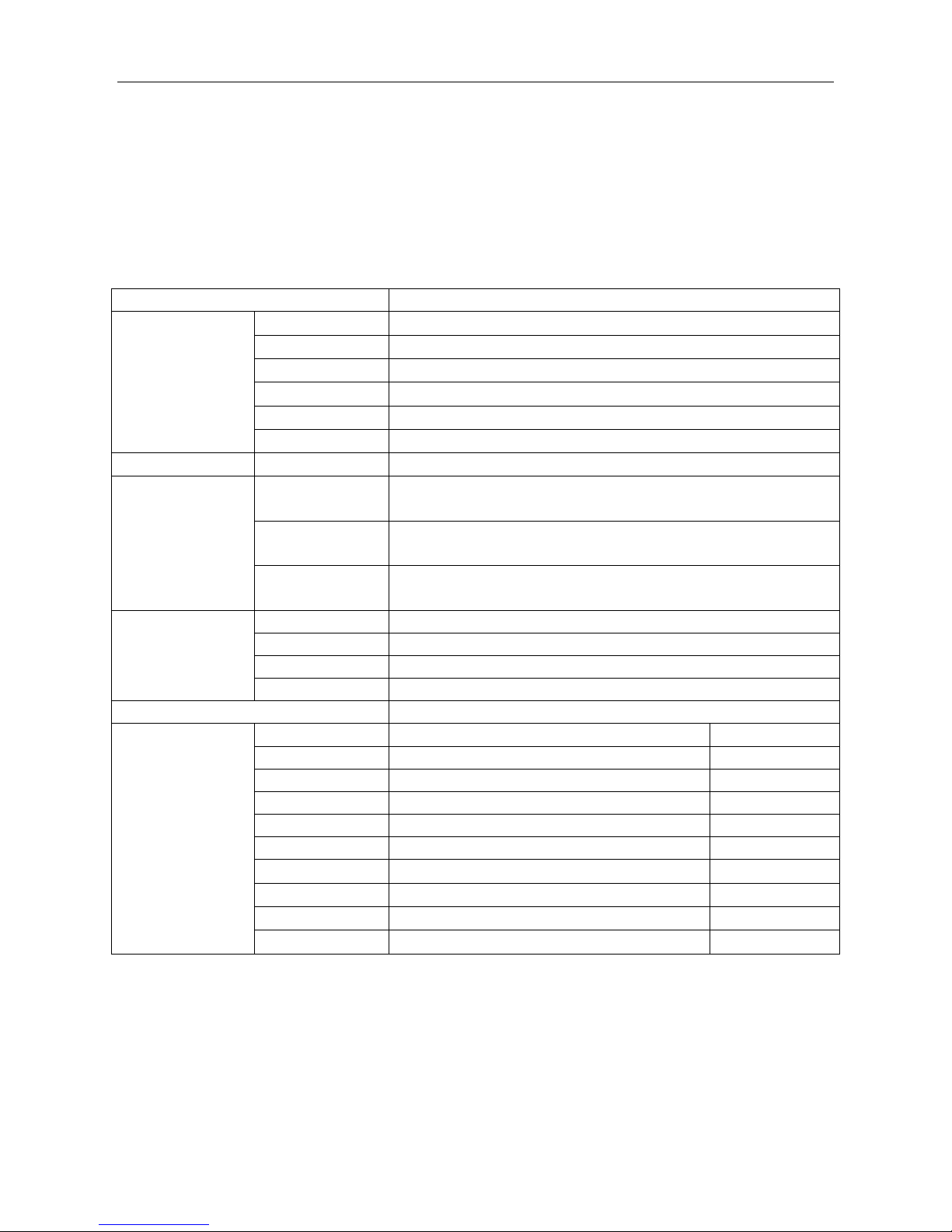
2. Specification
Remarks :
Inlet water:TDS<200ppm, 25℃, 50psi and 15% recovery rate.
GPD=gallon per day.1gallon=3.78liters.
The quality of inlet water will effect pure water’s quality of outlet and cartridge’s life.
Output of 100 gallons per day is measured under the temperature of 25℃. When the temperature is lower
than 25℃,the water output will be less than100 gallons per day.
Model
Master-S UVF
Quality of Ultrapure
water
Resistivity
18.2 MΩ.cm
TOC
<3ppb
Endotoxin
<0.001EU/ml
Bacteria
<1 CFU/ml
Particle (>0.1μm)
<1/ml
Heavy metal ion
<0.1ppb
Quality of RO water
TDS(ppm,mg/l)
< TDS of tap water×5%
Control
system
Mode display
Power on, program, inlet rinse, producing, full, circle, regular outlet,
disinfection, consumables replacing remind
Safety
Low pressure and full water alarm, password , auto-reset, outlet forbidden
when alarm or disinfection
System monitor
Monitoring quality of inlet water, RO water and ultrapure water,
temperature , used and left time of consumables
Technical
specification
Output
30 liters/hour*
Power
220V/50Hz, 120W
Dimension
W×D×H:50cm×36cm×54cm
Weight
About 20KG
Inlet water requirement
Tap water:TDS<200ppm,5-45℃,1.0-4.0Kgf/cm2
Purification
system
Sequence number
Specifitation
Quantity/set
LV.1
5µm spun pp filter
1
LV.2
Kinetic degradation fluxion filter
1
LV.3
Granular active carbon filter
1
LV.4
100gpd ro membrane
1
LV.5
Double wavelength(185&254)nm uv cartridge
1
LV.6
Post active carbon filter
1
LV.7
Ultrapure polishing resin cartridge
4
LV.8
5000 doulton uf cartridge
1
LV.9
(0.45+0.1)μm terminal filter
1
Page 3

Water Purification System Instruction Manual
2 / 11
3. Master-S UVF Water Flow Chart
4. Working Environments
Inlet water: Tap water (TDS<200ppm will be suggested).
If inlet water TDS>200ppm, pretreatment is recommended. Water with higher TDS will affect
the quality of outlet water and life of purification cartridge.
Work temperature: 5-45℃
Pressure: 1.0-4.0Kgf/cm2
Power: 220V/50Hz,120W
【Clean, dry working environments would be suggested!】
5. Installation Step
The purification system should be installed horizontally and near to tap water.
Tube installation and drag
The adapter of the machine is high quality easy-put adapter.
Proper usage is as follows:
Connect the tube: press the oval cap of the interface strongly, then insert the tube to the bottom of
adapter.
Take off the tube: press the oval cap of the interface strongly, then drag out the tube. Do not drag when
the tube can not be dragged out any more.
Tube installation and drag
All cartridges have been installed in the factory. Additional cartridges installation is unnecessary.
Check the accessory box. According to the “instaIlation guide chart” in the instruction manual, install the
machine with the adapters, tube and pretreatment filters(optional) in the accessory box. Connect with
the water tank, electrical source and tap water. At the end, turn on the power switch and the tap water
source valve, then the machine will produce pure water.
Page 4

Water Purification System Instruction Manual
3 / 11
Specific installation steps are as follows:
(1). Connect to tap water-1st step:
Shut off the chief switch of tap water, dismantle the tap, connect the water source with
3-direction-links in the accessories, and then connect the tap with 3-direction-links, connect
another direction of 3-direction-links with plastic ball valve. At last, open the chief switch of tap
water.
(2). Connect to tap water-2nd step:
Use 1/4” PE tube with a suitable length. One side connects with the plastic ball valve, and the other
connects with the interface with blue label marked “To inlet water” at the back of machine.
(3). Connect to RO drain:
Use 1/4” PE tube with a suitable length. One side connects with the interface with black label
marked “To drain” at the back of machine, and the other side is directed to gutter.(Do not jam)
(4). Connect to UF drain:
Use 1/4” PE tube with a suitable length. One side connects with the interface with green label
marked “To UF drain” at the back of machine, and the other side, through “UF drain valve”, is
directed to gutter.
Attention:
The “UF drain valve” is shut on normal condition, except for flushing UF membrane.
(5). Connect to water tank:
Install the plastic ball valve on the pressure tank. Use 1/4” PE tube with a suitable length. One
side connects with the interface with yellow label marked “To water tank” at the back of machine,
and the other connects with the plastic ball valve.
Thus the installation is OK.
Page 5

Water Purification System Instruction Manual
4 / 11
Installation Guide Chart
RO membrane drain
(Do not jam)
RO water outlet:
Application:
ware washing,agricultural
expe,general biological expe,aquatic
products feeding,inlet water for ultra
pure water machine,inlet water for
sterilizer/ t&h chamber
Terminal filter
Tap water
Tap water adapter 2
Tap water adapter 13-direction-links
Plastic ball valve
OR
Ultrapure water outlet:
Application:
GC,HPLC,IC,ICP
PCR,weather analyse
Amino acid analyse
Reagent preparation
UF drain valve
UF membrane drain
Plastic ball valve
4 gallon water tank
Page 6

Water Purification System Instruction Manual
5 / 11
6. Usage Guide
All data have been set in the factory. The machine will operate smoothly without any data-setting. All work state
will display in the LCD. If there is abnormal state, the system will alarm automatically. If data modification is
necessary, specific step is in “Microcomputer Controller”.
The power switch and “on-off duty” work model switch are at the back of the shell.
Specific picture is as follows:
“on-off duty” work model switch is as follows. (Remarks:”On duty” work mode is recommended)
Starting up:
Turn on the tap water valve, insert the power line into the power source and turn on the power switch, then
the system begins to produce pure water.
Getting corresponding pure water:
Press “RO” or ”UP” key-press, which are on the panel, to get corresponding RO water or Ultrapure
water(higher quality water than RO water).
Standby:
When RO water and Ultrapure water is not for use, the system will be in standby state. The system still
produce RO water to store in the water tank(optional). Until tank is full, the system will automatically stop.
The system will begin to produce pure water again when any pure water is used.
Shutdown:
Turn off the tap water valve and turn off the power switch. Then it is ok.
Flushing UF membrane
Method of flushing UF membrane:
Turn on the UF drain valve, and press ”UP” key-press, which are on the panel, to turn on Ultrapure water’s
valve
Attention: The “UF drain valve” is shut on normal condition, except for flushing UF membrane.
Frequency of flushing UF membrane:
At least one times every week, and at least listing 30 seconds every times.
Attention: Make sure that the water source and power source is not connected when the system is
not in the use state for long time(for example, off duty).
On duty model
Stand by
Off duty model
Turn on the power
Turn off the power
Page 7

Water Purification System Instruction Manual
6 / 11
The usage to keep high quality pure water:
(1). The Ultrapure water is easily polluted by surrounding environment. So getting fresh pure water is
suggested.
(2). Keep source water tank from sunlight for microbe’s reproducing.
(3). When get high pure water, initial high pure water is suggested to drain to get steady pure water.
(4). Avoid air bubble when get pure water to reduce air pollution.
Attention: The microbe’s reproducing will reduce the life of filter cartridge when the machine does not
work for long time. So the machine’s work every 7-10days is necessary.
7. Microcomputer Controller
Panel
There are 6 key-press on the panel. As follows:
6 key-press from left to right:
“RO” key-press: open or close RO water valve.
“MENU” key-press: main menu, all the data of the system will be set in the menu.
“ ” key-press: choose the 1000,100,or 10-bit of set data. chosen position will show anti-color status.
“ ” key-press: adjust the data of chosen position(0-9circle)
“OK” key-press: confirm the adjusted data and execute corresponding function.
“UP” key-press: open or close Ultrapure water valve.
Remarks:
The initial code is “1000”. After pressing “MENU” key-press, “please in code” will appear. Inputting the
code “1000” through shiftin “ ” and “ ”, then entering the main menu.
Control system brief introduction
(1). When power is switched on, the LCD will displays“”(picture 1)for 5 seconds.
picture 1 picture 2
(2). After 5 seconds, the system will check the state of inlet water source. No inlet water or low pressure of inlet
water, the system will warn (picture 2).If the state of inlet water source is ok, system will implement the
following program.
(3). Check the conductivity of inlet water. Compare with previously set down conductivity of alarm. Check
whether the current conductivity of inlet water exceeds the previously set down conductivity of alarm. If so,
display the current exceeded conductivity and warn (picture 3).(for the following “flush” program (picture 4),
press “OK” key-press is needful)If not, system will switch to “flush” program (picture 4).
picture 3 picture 4
(4). Under “flush” state (picture 4), RO membrane will be flushed for 25 seconds. Meanwhile system checks
the state of inlet water. No inlet water or low pressure of inlet water, the system will warn (picture 2). When
Page 8

Water Purification System Instruction Manual
7 / 11
inlet water is ok, system goes on flushing RO membrane.
(5). After “flush” state, system switches to “pure water produce” state (picture 5) to produce pure water.
Meanwhile check the state of inlet water and water tank. When tank is full with RO water (picture 6),
system will warn. After a few seconds, system will switch to main interface (picture 7).
picture 5 picture 6 picture 7
If the water tank is not full with RO water, also press “OK” key-press to switch to main interface
(picture 7). At this time, the system continues producing pure water. Under the main interface, all the
function operation can be carried out.
System alarm
(1). · No water alarm: System will check the state of inlet water source in real time.
A. When power is on and the system is flushing RO membrane, the system will warn for no inlet water or
low pressure of inlet water. The sound and picture (picture 2) of alarm will not stop until the state of
inlet water is ok. And system will implement flush program again.
B. When system is producing pure water, it will warn for no inlet water or low pressure of inlet water. The
sound and picture (picture 2) of alarm will not stop until the state of inlet water is ok. And system will
produce pure water again.
C. When system is under working conditions, it will warn for no inlet water or low pressure of inlet water.
The sound and picture (picture 2) of alarm will continue for 3 seconds. Then system goes on working
after 3 seconds. The system will check state of the inlet water after 1 min.
(2). · Parts life alarm: pre-treat part(picture 10)and UV lamp (picture 11).
When work time of parts surpasses previously set down part life, the system will continue to warn for
3 seconds. And system will check the parts life again 1 hour later. In the following time, system will
warn 1 times every 1 hour till previously set down part life is extended or cleared.
picture 10 picture 11
(3). · Ultrapure polishing resin cartridge alarm:
When resistivity of Ultrapure water is lower than previous set down resistivity, system will warn for UP
cartridge’s replacing (picture 12). (At this time, Ultrapure water valve is shut down. And if the
Ultrapure water valve is being opened, then it will be shut down immediately and switched to
recirculation state). After 10 seconds, system will check the resistivity again.
picture 12
Menu code setting method.
Under the main interface (picture 7), press “MENU” key-pres and “OK” key-press in turn to switch to code
confirmation state (picture 14). Then through pressing “ ” key-press and “ ” key-press to enter
Page 9

Water Purification System Instruction Manual
8 / 11
password(In this process, if password is not right, system will warn.) At last press “OK” key-press to switch
to menu interface(picture 15), After switching to menu interface, through pressing “MENU” key-press, shift
cursor to corresponding item menu, then press “OK” key-press to enter corresponding item.
picture 14 picture 15
(1). Conductivity(TDS) parameter setting(picture 16):
Under the menu interface(picture 15), press “MENU” key-press to shift the cursor to choose “TDS”
item, then press “OK” key-press to enter ”TDS” parameter setting(picture 16).
Press “MENU” key-press to choose modified item, and press “ ” key-press to choose modified
place, and press “ ” key-press to amend the parameter. When amending is ok, press “OK”
key-press for system’s confirmation. If back to main interface is necessary, press ”MENU” key-press
to shift cursor to icon at the right bottom of the LCD and press “OK” key-press to return to main
interface.
(In the following item parameter setting process, the method is equivalent to the
conductivity(TDS) parameter setting’s.)
TDS1: inlet water conductivity test.
Max: inlet water conductivity’s upper limit alarm parameter of TDS1.
Min: inlet water conductivity’s lower limit alarm parameter of TDS1.
Remark:
TDS1(hysteresis of inlet water conductivity =Max-Min) upper and lower alarm test only work when
power is on. When current test parameter > TDS1’s Max, the current test parameter will display and
system will warn. System will stop warning when current test parameter <TDS1’s Max.
TDS2: RO water conductivity test.
Max: RO water conductivity’s upper limit alarm parameter of TDS2.
Min: RO water conductivity’s lower limit alarm parameter of TDS2.
Remark: When current test parameter of RO water > TDS2’s Max, the current test parameter will
display and system will warn. System will stop warning when current test parameter <TDS2’s Max.
EC: electrode parameter setting (Parameter setting is OK in factory. Additional parameter setting is
unnecessary.)
TCQ: temperature compensation parameter setting(Parameter setting is OK in factory. Additional
parameter setting is unnecessary.)
picture 16 picture 17
(2). Resistivity parameter setting
Under the menu interface(picture 15), press “MENU” key-press to shift the cursor to choose “Resist”
item, then press “OK” key-press to enter ” Resist”” parameter setting(picture 11).
Max: resistivity’s(Ultrapure polishing resin cartridge’ life)upper limit alarm parameter.
Min: resistivity’s(Ultrapure polishing resin cartridge’ life)lower limit alarm parameter
Remark:
The “Min” determines alarm of Ultrapure polishing resin cartridge’ life. When current test parameter of
Page 10

Water Purification System Instruction Manual
9 / 11
resistivity < The “Min”, system will warn to replace the Ultrapure polishing resin cartridge. When
current test parameter of resistivity < The “Min”, system will stop warning.
EC: electrode parameter setting (Parameter setting is OK in factory. Additional parameter setting is
unnecessary.)
(3). Parts’ life setting / parts’ runtime clear
Under the menu interface(picture 15), press “MENU” key-press to shift the cursor to choose “Parts”
item, then press “OK” key-press to enter ”Parts” setting(picture 18).
Pre-treat: pre-treat’s lift setting. (range: 0-9999 hours)
UV lamp: UV lamp’s life setting. (range: 0-9999 hours
picture 18
Pre-treat runtime: clr - Pre-treat runtime clear.
UV lamp runtime: clr - UV lamp runtime clear.
(press “MENU” key-press to shift the cursor to choose corresponding “clr” icon, then press “OK”
key-press to clear runtime. And system will restart timing)
(4). Code setting
All system’s initial code is “1000”
Under the menu interface(picture 15), press “MENU” key-press to shift the cursor to choose “Code”
item, then press “OK” key-press to enter ”Code” setting(picture 19). Press “ ” key-press to choose
modified place, and press “ ” key-press to amend the parameter. After amending code, system will
use new code for entering menu interface.
picture 19
(5). RO water, Ultrapure water timing dispense setting
Under the menu interface(picture 15), press “MENU” key-press to shift the cursor to choose
“dispense” item, then press “OK” key-press to enter ”dispense” setting(picture 20). 2 kind dispense
mode is optional-“Manual” and “Auto”. When system enters “Auto” dispense mode, timing setting is
viable.
UP out: Ultrapure water timing dispense setting (only for “Auto” dispense mode)
RO out: RO water timing dispense setting (only for “Auto” dispense mode)
picture 20
8. Water Quality Test
The system has 3 monitor sensors of water quality measuring.
The first, TDS1, monitors feed water’s quality (tap water, inlet water).
Measure unit: TDS(total dissolved solid, ppm)
The second, TDS2, monitors reverse osmosis water’s quality(RO water).
Page 11

Water Purification System Instruction Manual
10 / 11
Measure unit: TDS(total dissolved solid, ppm)
The third, Resist, monitors Ultrapure water’s quality (Ultrapure water).
Measure unit: Resistivity (MΩ.cm)
Remarks:
Conversion relations between TDS and conductivity rate(µs/cm):
If TDS<50ppm. conductivity rate(µs/cm) ≈TDS×2
If TDS>200ppm. conductivity rate(µs/cm) ≈TDS×(1.5~1.7)
If TDS2 of RO water < TDS1 of inlet tap water×10%(under normal conditions, TDS2 of RO water is around
TDS1 of inlet tap water×5%), RO membrane is ok. If TDS2 of RO water > TDS1 of inlet tap water×10%,
Replacing RO membrane is essential for proper pure water.
9. Consumables
Item No.
Commodity
Quantity/set
Suggested replacement term
PC-M-PP
5μm spun fiber filter
1
About 2-6 months
PC-M-KDF
Kinetic degradation fluxion filter
1
About 4-6 months
PC-M-AC-G
Granular active carbon filter
1
About 4-6 months
RO-100GPD
100 gpd ro membrane
1
About 12-24months
LAMP-(185nm&254nm)-10W-M
Double wavelength(185&254)nm uv
lamp
1
About 9000 hours
PTC-AC-HZB
Post active carbon filter
1
About 9000 liter pure water
PTC-UPPR-M
Ultrapure polishing resin cartridge
4
About 4000 liter pure water
UF-5000D
5000 doulton uf cartridge
1
-
TF-(0.45+0.1)μm-S
(0.45+0.1)μm terminal filter
1
-
Remarks:
Worse inlet source water quality or big dosage will reduce the life of cartridge above.
10. Trouble Diagnosis
Ⅰ. Motor failure
A. Check whether the pressure of the tap water is high enough. When pressure is low, low pressure switch
will cut off power.
B. Check whether the high pressure switch or water level controllor is normal.
C. Check whether special PP filter or Active carbon is blocked which cause the overload of the motor.
D. Check whether control panel is OK (for full automatic model)
Ⅱ. Pump Leaking
A. Check whether special PP filter or Active carbon is blocked which cause the overload of the motor.
Then high pressure lead to leaking. Resolution: change special PP filter or Active carbon and repair the
pump.
B. The expiring of the pump rubber membrane or the dirt will cause leaking too. Please repair the pump
and pay attention to checking the LV. 1-special PP cotton.
C. The block of the waste water proportion vessel will cause the block of the reverse membrane. Then
pressure increase. Water with high pressure will break the pump rubber membrane, then causes
leaking. Change relative components will be ok.
Page 12

Water Purification System Instruction Manual
11 / 11
Ⅲ. Motor working but no water
RO membrane is blocked or pump’s pressure lost. For the former, change the RO membrane; For the later,
check whether expiring of pump is caused by long time overload or blocking of the cartridge. Repair motor.
Ⅳ.Motor works ever and again
The motor works ever and again. It is the reason that low pressure or blocking of LV.1cartridge. Please
install a booster pump or replace LV.1cartridge.
Ⅴ.The pressure tank is full of water, but pure water can not flow out
A. Air in the pressure tank leaks. Please fill it with 7psi air and check whether air leaks. If air can not be
put into tank, change the pressure tank..
B. Backset active carbon is blocked. Please replace it with a new one.
Ⅵ. Power is off, but RO water does not stop flowing.
A. Check the four-side water circuit breaker, and replace it if it goes wrong.
B. Pressure of inlet water is higher then the set pressure of high pressure switch. Please regulate the
pressure of inlet water no more then 2kg/cm2.
Ⅶ. The machine can not stop running when pressure tank is full of water or it runs at once after one stop.
A. High pressure switch or liquid level controller goes wrong. Repair it if it works after repairing, otherwise,
replace it with a new one.
B. Non-return valve leaks pressure so that it can not close. Replace it please.
11. Warranty & Repair Regulation
The products customers buy form our company enjoy repair service since the day of purchase. In on year
form the purchasing day, our company is obliged to replace components free of charge due to
non-human-behavior factors except:
(1). Damage caused by maloperation or use in abnormal situations.
(2). Disassembly any part of the machine or human-behavior damage.
(3). Not repaired by our serviceman.
Specification can be changed without any prior notice for development
 Loading...