

Page 1
11
1) While the push rod to transmitted or reflected is to the working
position “R”, fluorescent microscopy can be used.
2) Reduce the field diaphragm, If it is not centered, move it to the
center using the special tool. Adjustment can be done by opening the
field diaphragm.
3) The push rod to direct image to binocular eyepieces or camera port
to the upper left of the trinocular head will send 100% of light to the
binocular eyepieces or to the top port. It satisfies high-grape
photography, see figure 7.
Preventative Maintenance
1. Cleaning frame and stage
Disconnect the plug from mains socket before cleaning. Clean the frame
and stage with a soft cloth moistened with a mild detergent solution. Be
sure the instrument is dry before using.
2. Cleaning optical parts
Microscope eyepieces and objectives are coated. They should not be
wiped while dry as dirt or dust may scratch the coating. It is best to
remove parts from the frame prior to cleaning. Always blow loose dust
away first. Use cotton swabs or lens tissue moistened with a lens cleaner
or a small amount of alcohol, then wipe the surface clean with a good
quality lens tissue. Solvents such as Xylene should NOT be used as
cleaner.
3. Cleaning 100X oil immersion lens
The immersion oil should be removed from the lens at the end of each
workday using cotton swabs or lens tissue moistened with a lens cleaner
or a small amount of alcohol.
LED Epifluorescence Microscope
L3201LED
User Guide
HAGAVISH 3,HOLON, ISRAEL
TEL: 972-3-5595252, FAX. 972-3-5594529
mrc@mrclab.com
Page 2
1
Congratulations and Thank You for your purchase of
The Microscope
This precision instrument has been designed to require a minimum of optical
and mechanical maintenance. Its excellent design assures years of high quality,
reliable service. We recommend you read this entire manual carefully before
beginning to use the instrument.
WARNING
PLEASE DISCONNECT PLUG FROM MAINS SOCKET BEFORE
REMOVING THE BOTTOM PLATE, OPENING THE LAMP
REPLACEMENT DOOR, OR REMOVING THE LAMP HOUSE
WARNING
THE POWER CORD PROVIDED WITH THE EQUIPMENT HAS A
GROUNDED PLUG. ALWAYS USE THE POWER CORD WITH A
PROPERLY GROUNDED WALL OUTLET.
DO NOT EXPOSE THE INSTRUMENT TO HIGH TEMPERATURES OR
HUMIDITY. AVOID USING THE INSTRUMENT IN EXTREMELY DUSTY
LOCATIONS
OPERATING TEMPERATURE 5 DEGREE C. TO 35 DEGREE C.
OPERATING HUMIDITY: 20% TO 80% @ 25 DEGREE C.
CAUTION: NEVER IMMERSE THE INSTRUMENT IN WATER OR
SOLVENT
CAUTION: DO NOT PUT ANY FOREIGN OBJECTS IN THE FRAME OR
INTO ANY MOVING MECHANICAL PARTS
10
swing the attachment lens to optical center.
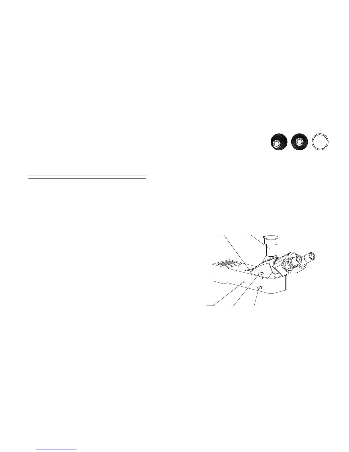
6. Condenser Alignment – to center the Abbe condenser into the optical
light path, see figure 6:
1) Close the field iris diaphragm.
2) Observe the image using the 5X
objective and you will see an
image similar to figure 6 A. The
image may be out of focus and out
of center.
3) To center the field iris diaphragm in the field of view, use the two
centering screws at each side of the Abbe condenser mounting ring, see
figure 6 B.
4) Once the image is in focus and centered in the field of view, open the
field iris diaphragm until the image is almost as large as the field of
view, see figure 6 C.
7. Fluorescent Illumination Alignment, see figure 7.
A B C
Figure 6
4
1 2
3
1. Field Diaphragm Adjustment Knob 2. Camera Port 3. Push Rod
To Transmitted or Reflected 4. Push Rod To Direct Image to
Binocular Eyepieces or Camera Port Compensator 5. Field
Dia
p
hragm Centering Screw
5
Page 3

9
1) Diopter Adjustment Proper correction for individual vision is
accomplished via the diopter adjustment located at the left eyepiece.
Using the 10X objective, bring an
image into focus with your right eye
only. Once the image is well focused,
observe with left eye, make fine
adjustments with the diopter
adjustment ring to correct for your
vision.
2) Proper interpupillary distance, or
the distance between eyepieces, is
crucial to the comfort of the user.
Adjusting the interpupillary distance
is accomplished through a “folding”
action of the optical head, at Figure 4,
allowing for quick and easy
adjustment.
4. Mechanical Stage Control, see figure 5.
The coaxial transverse / longitudinal
knob allow for easy adjustment.
5. Condenser Components – are located
below the stage as follows, see figure 5.
Abbe condenser; its mounting ring with
set screw and two large centering
screws at either side for adjusting
condenser/iris assembly in the optical
center of the light path; the substage
adjustment knob for raising and
lowering the condenser. Upon the
collector is field diaphragm to hold the
filters.
Note: Using the 5X objective can be
Figure 4
Diopter Adjustment Ring
1.Substage Adjustment Knob
2.Slide Holder 3. Condenser Set
Screw 4. Condenser Centering
Screw 5.Iris Diaphragm Control
Lever 6.Longitudinal Adjustment
Knob 7.Transverse Adjustment
Knob
Figure 5
1
2
3 4
6
7
5
2
Table of Contents
Getting Started ...................................................................................................3
Components .......................................................................................................4
Technical Specifications.....................................................................................6
Setup Instructions............................................................................................... 7
Basic Operation.................................................................................................. 7
Preventative Maintenance................................................................................ 11
Page 4

3
Getting Started
This reference guide is written base on whole series, it covers some capable
optional attachments and functions, you may read the similar operation what
you need.
8
3) Reflection Illumination Press the transmitted / reflection illumination
toggle switch on the side of “Ⅱ”, which means the reflection
illumination is used.
2. Focusing Controls, see figure 3
1) Focusing adjustment is accomplished by using the large coarse
adjustment knobs located comfortably on each side of the frame. Fine
adjustment is accomplished using the smaller knobs located on the
same focus shaft. This coaxial arrangement allows for easy, precise
adjustment without drift or discomfort.
2) Focus Control Turning either of the coarse focus control knobs will
raise or lower the stage. The smallest graduation on the fine adjust
knob index scale is 2μm of vertical.
3) Focus Tension Adjustment The tension of the coarse focus is
adjustable and preset at the factory for ease of use. If you wish to adjust
the coarse focus tension, first locate the tension adjustment ring.
Turning the ring toward the front of the microscope increases the
tension, and toward the rear of the microscope loosens it. Tension is too
high if you experience physical discomfort.
4) Pre-focusing or Focus Stop Control. Use of this feature will insure
that the short working distance objectives don’t contact the stage or
slide glass when using the microscope. Its use also simplifies focusing.
After focusing on the slide glass with the coarse adjustment, rotation of
the lever toward the rear of the microscope will set an upper limit on
the coarse adjustment movement. After changing slide glass or
objectives, focusing is easily accomplished by rotating the coarse
adjustment knob to reach the pre-focused position, then making fine
adjustments with the fine adjustment knob. Focusing movement with
the fine adjustment isn’t affected by using the pre-focusing lever.
3. Diopter and Interpupillary Adjustments
Page 5

7
Adapter: Input: 110V~240V 50/60Hz
Output: 12V
Setup Instructions
1. Remove all parts from their packing materials and retain the packaging in
the event you need to transport the product.
2. Connect the power cord to power outlet.
Basic Operation
1. Illumination controls, see figure 3
1) The external power switch and
transmitted / reflection
illumination toggle switch are
located on the base. The
brightness control is located on
the chassis. The electrical system
is fuse protected and the fuse
holder located on the power Inlet.
2) Transmitted Illumination Press
the transmitted / reflection
illumination toggle switch on the
side of “Ⅰ” , which means the
circuits is got through. If the light
does not appear to be ON, check
the brightness control to see if it’s
on a sufficiently low setting. Then
adjust the brightness control until
image can be observed comfortably.
Note: Using the light at brightest setting reduces life span of bulb.
Figure. 3
1. Transmitted / Reflection
Illumination Toggle Switch 2.
Power Switch 3. Brightness
Control 4. Up Stop Knob 5. Focus
Tensional Adjustment 6. Coarse
Focus Control Knob 7. Fine Focus
Control Knob
1 3
4
5 6 7
2
4
Components
1. Field Diaphragm
Adjustment Knob 2. Push Rod To Direct Image to
Eyepieces or Camera Port 3. Baffle 4. Condenser Centering Screw 5.
Longitudinal Adjustment Knob 6. Transverse Adjustment Knob 7. Field Iris
Diaphragm 8. External Power Switch 9. Transmitted / Reflection Illumination
Toggle Switch 10. Fine Focus Control Knob 11.Coarse Focus Control Knob
12. Focus Tensional Adjustment Knob 13. Substage Adjustment Knob 16 .
Push Rod To Transmitted or Reflected
Figure. 1
4
1
5
6
7
10
11
12
13
2
3
14
8
9
Page 6

5
1. Eyepiece 2. Trinocular 3. LED lamp box 4. Stage 5. Filter Seat 6. Up
Stop 7. Brightness Control Knob(Transmitted Illumination) 8. Attachment
Lens 9. Condenser Iris Diaphragm 10. Condenser Set Screw 11. Light guard 12.
Objective 13. Nosepiece
2 1
13
12
10
6
5
Figure. 2
9
8
4
7
3
6
Technical Specifications
Trinocular: Inclined 30°.
Objectives: Plan achromatic objectives
Nosepiece: Quadruple/Quintuple nosepiece ball-
b
earing reversed nosepiece with positi
v
Eyepieces: 10X Plan wide field, focal length 25mm, Field Φ20mm.
Stage: 210mm X 140mm, range of motion 75mm X 50mm. Integrated
mechanical stage with vernier, low-position coaxial control
knobs.
Focus Mechanism: Adjustable tension control to prohibit drift and adjustable
up-stop to protect slides, slide glass and objective lenses;
Coaxial coarse and fine adjustments with dial markings at 2μm
increments.
Condenser: N.A. 1.25 Abbe condenser with iris diaphragm, rack and pinion
focusing.
Transmitted Illumination: 3W High brightness white LED, brightness
adjustable.
Reflected fluorescence system: 3W blue LED (460~470nm), with blue
fluorescent filter system. Brightness cannot adjustable.
Magnification
N.A. W.D. (mm)
4X 0.10 19.75
10X 0.25 5.0
40X 0.65(Spring) 0.66
100X 1.25(Spring, Oil) 0.36
 Loading...