

Page 1
Operation Manual for
Infrared Cameras
IR-CAM-B-70/I-75/B-90/I-95
PLEASE READ THIS MANUAL CAREFULLY
BEFORE OPERATION
3, Hagavish st. Israel 58817 Tel: 972 3 5595252, Fax: 972 3 5594529
mrc@mrclab.com
MRC.VER.01-3.12
Page 2

To Our Customer
Dear Customer:
Thank you for choosing this Infrared Camera!
Please read this user manual carefully before first use.
Also please keep in a safe place for reference in the
future.
Please operate with the recommended instructions in
user manual.
We reserve the right to change this user manual without
further notice.
Page 3

N O T I C E
In order not to cause malfunction or even damage the device please
do not direct the lens towards strong high-temperature radiation
source (such as the sun) whether the power is on or off!
Avoid violent shock and impact during operation or transport.
Storage temperature is between -40OC and 60OC. The device must
be kept in original packing case during transport.
Typical storage place is cool, dry, ventilated, and without strong
electromagnetic field.
Keep the lens surface off grease or any chemical substance which
would damage the lens. Close the lid after operation.
Please regularly backup data on PC to prevent potential data loss and
format the internal FLASH memory duly to make it operate properly.
WARNING
DO NOT OPEN OR EXCHANGE PARTS!
REPAIR ONLY CAN BE CONDUCTED BY STUFF!
Page 4

i
Table of Contents
1. Product Summary.......................................................... 1
1.1 Standard Item List...................................................... 1
1.2 Optional Item List....................................................... 2
2. Battery and Charger...................................................... 2
2.1 Charging Battery........................................................ 3
2.2 Direct Charging.......................................................... 3
2.3 Attention for Using Battery Charger........................ 3
3. Panel Function Summary............................................ 3
3.1 Main Control Panel.................................................... 4
3.2 Side View.................................................................... 7
3.3 Bottom View................................................................ 8
3.4 Left Side View............................................................. 8
4. Quick Start Reference .................................................. 9
4.1 Battery Setting............................................................. 9
4.2 Quick Operations....................................................... 9
4.3 Measure Target Temperature................................. 10
4.4 Infrared Image and Voice Annotation................... 10
4.5 Infrared Image Playback......................................... 10
4.6 Telephoto and Wide-angle lens............................. 11
4.7 Connect to PC.......................................................... 12
4.8 Video and Audio output........................................... 12
5. Operation Menu............................................................ 12
5.1 Display Summary..................................................... 12
5.2 Main Menu................................................................ 14
5.2.1 File..................................................................... 16
Manage........................................................... 16
Save................................................................ 17
Record & Play................................................ 17
Delete.............................................................. 18
Format............................................................. 18
5.2.2 Measure............................................................ 19
Spot Measure................................................. 19
Line Measure................................................. 21
Horizontal Line Measure.......................... 21
Vertical Line Measure............................... 22
Page 5

ii
Area (Rect) Measure.................................23
Parameters................................................... 24
Emissivity....................................................25
Distance...................................................... 25
Adjust Ratio................................................ 25
Adjust Temp............................................... 25
Save Setting................................................... 26
5.2.3 Image................................................................ 26
Image Setup................................................... 26
Alarm Switch.............................................. 27
Alarm Temp................................................27
Alarm Color................................................ 27
Isotherm Color........................................... 27
Isotherm Temp.......................................... 27
Hot Superposition......................................28
Thermal Superposition Attribute..............29
Fusion......................................................... 30
Alarm Color................................................ 33
Analysis Setup............................................... 33
Temp Range.............................................. 34
IR Lens ....................................................... 34
Ambient Temp........................................... 34
Reference................................................... 35
Ref Temp.................................................... 35
Image Reverse.............................................. 35
Clear Screen.................................................. 35
L&S (Auto/Manual Mode)............................. 35
5.2.4 Setup................................................................. 35
System Setup................................................. 36
Language....................................................36
Auto Rectify................................................ 36
Auto Save................................................... 36
Video........................................................... 36
Transparence............................................. 37
Display Device........................................... 37
Screen Save.............................................. 37
Page 6

iii
Power Save................................................ 37
Storage Medium........................................................ 37
Time & Date................................................... 38
Factory Default.............................................. 38
System Information....................................... 40
Disc Information............................................. 40
6. Building Thermal Imaging Summary...................... 41
7. Technical Specifications............................................43
8. Technical Support........................................................45
Page 7

iv
Page 8

1
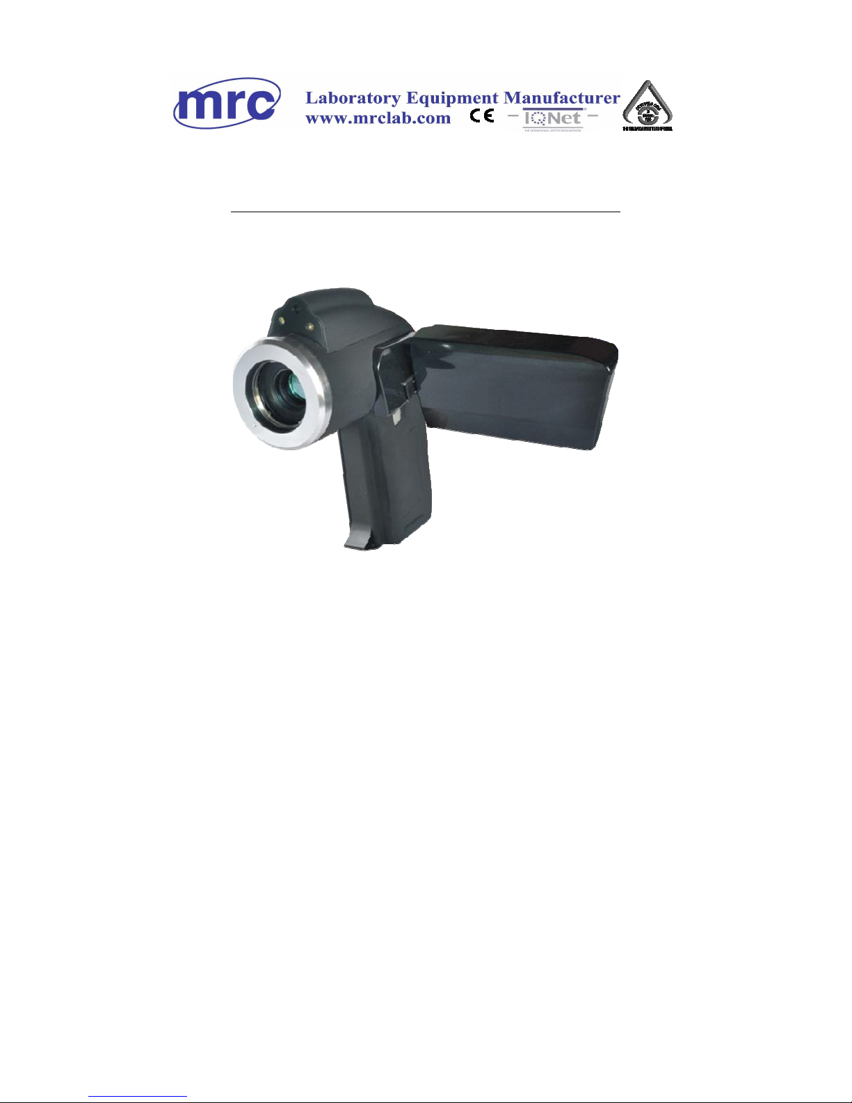
1. Product Summary
The Infrared Camera (equipped with Uncooled Focal Plane Array
Micro-bolometer) produces crisp thermal image and accurate temperature
reading to help increase system maintenance quality and efficiency in
many industries. The Infrared Camera is packed with advance features,
such as colored thermal images, multi-measurement methods, real-time
video, voice annotation, sound and color alarm, IR fusion, Built-in flash
and SD card storages.
Typical Application:
Power Industry: Monitor and diagnose the condition of electrical
wire and equipment, detect power leak, and prevent system
malfunction.
Petrochemical Industry: oil pipeline check, material interface detect,
heat leakage, insulation structure and power equipment detect.
Fire Protection: forest fire protection and latent fire source search,
self-ignition prevention and detection of special material, electric fire
precaution detect.
Medical Application: Accurately measure human body temperature
and analyze temperature field distribution.
Building Industry: humidity, air leakage and insulation defects
detect.
Other Applications: Civil engineering, scientific research, and
railway etc
1.1 Standard Item List
The infrared camera comes with the following standard items and
accessories:
Page 9

2
Name Quantity
Infrared Camera
1 SET
Li-Ion Battery
2 PCS
Charger
1 PC
SD Card
1 PC
SD Card Reader
1 PC
USB Cable
1 PC
Video Cable
1 PC
Converter cable
1 pc
User Manual
1 PC
IRSee Software CD
1 PC
Adapter
1 PC
Transport Case
1 PC
1.2 Optional Item List
Wide-angle lens
Telephoto lens
2. Battery and Charger
It is recommended to charge battery immediately when device indicates
low power, please read more about battery installation and removal
methods on Page 8.
Device comes with two sets of Li-Ion battery and one battery charger. It is
strongly recommended to operate only with the included battery and
charger. Use any other brand charger or Li-Ion battery may cause fire or
critical damage.
Page 10

3
2.1 Charging Battery
Align the notch of the battery at the charger’s mount, press the
battery downward gently along the triangular arrow, and fit it to the
end.
Connect the charger to an AC outlet, during charging, the red LED
will be on, and when charging is completed, the green LED will be on
instead.
: It is about 4 hour s to completely charge one battery.
2.2 Direct Charging
It is available to charge the built-in battery with the adapter; it is about 5
hours to fully charge a run-out battery. The indicator indicates orange in
charging and remains green when fully charged.
2.3 Attention for Using Battery Charger
Battery Charging can only be conducted inside of a house.
Do not short-circuit the battery.
Do not put the battery in high temperature environment (≥60OC).
Never disassemble the battery or put it into fire, which may cause
explosion.
Do not try to modify the battery or the charger.
Li-Ion battery has no memory effect, charging can be conducted at
any time.
Please remove the charger from AD socket as soon as charging is
completed.
3. Panel Function Summary
In this manual, “long press” means Long press button down for about 2
seconds, and “press” or “short press” means press and release.
Page 11
4
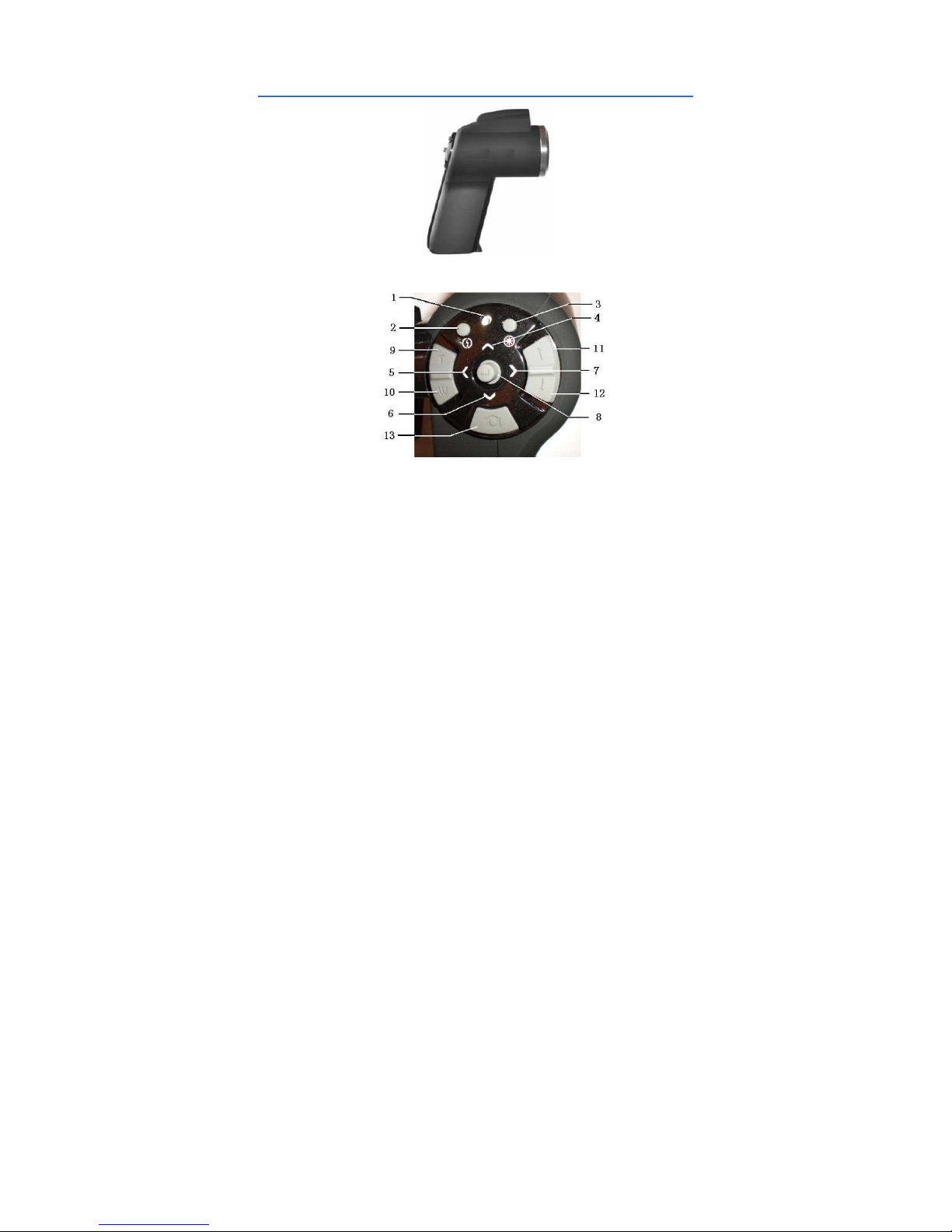
3.1 Main Control Panel
1. Power LED Light
After infrared camera is turned on, the indicator functions as a power
indicator in green; functions as a charging indicator in orange, indicating
the battery is being charged now.
2. HotKey button 1
Press to automatically focus, and Long press to turn on / off LED light.
3. HotKey button 2
Press to switch between measured objects (point, line and area), and
fusion zone, setting range of thermal superposing temperature, color
code, temperature upper and lower limits; and Long press to turn on / off
the laser.
Page 12

5
4, 5, 6,7 Direction buttons
Up ( ), Down ( ), Left ( ), and Right ( ) keys have different usages
in different modes.
In main menu, direction buttons are used for moving selected items or
changing slide-bar value. In real time Infrared view mode, directions
buttons provide one-click access.
In Fusion or Superpose imaging mode, press Right ( ) to make better
overlaying between visual and infrared images.
Press Left ( ) and Right ( ) to select preview images.
Press Left ( ) to freeze Infrared image and press again to unfreeze.
Press Up ( ), or Down ( ) to switch between normal view and 1-8x
zoom continuous
After press Hotkey button 2 in area measure(in yellow flashing) :
Select measured spots: press Up ( ), Down ( ), Left ( ), and
Right ( ) button to move the spot in the same direction.
Select the measure line and sampling line; press Up ( ), Down
( ), Left ( ), and Right ( ) button to move the line in the same
direction.
Select area box: in move menu, press Up ( ), Down ( ), Left ( ),
and Right ( ) buttons to move area box, and in size menu, press Up
( ) and Down ( ) to resize the vertical direction area box, press
Left ( ) and Right ( ) buttons to resize horizontal area box.
Select Fusion area: in fusion imaging mode, press Up ( ), Down
( ), Left ( ), and Right ( ) buttons to move infrared image area at
same direction; press Up ( ), Down ( ) buttons to resize vertical
fusion area; and press Left ( ) and Right ( ) buttons to resize
horizontal fusion area.
Select and set thermal superposing temperature range: in thermal
superposing imaging mode, press Up ( ) and Down ( ) buttons
to select slide-bar, and press the Left ( ) and Right ( ) keys to set
the superposing temperature upper or lower limit, as well as the
temperature values above or below the superposing temperature.
Page 13

6
Select Color Palette or temperature measurement limit: Press Left
( ) and Right ( ) to change Color Palette; and Press Up ( ) and
Down ( ) buttons to change temperature limit.
8. (Menu / Enter) button
This button has different functions under different conditions:
1).In real time Infrared view mode, press this button to open the main
menu.
2).In the menu mode, press the key to confirm operation.
3).In real time Infrared view mode, long press this button to manually
rectify measurement result, LCD screen will display the word “rectifying.”
4).In image viewing mode, long press this button to exit.
:
After auto rectifying, if device has abnormal noise, long press
button to perform manual rectifying usually solves such issues.
9, 10, Manual Focus (T / W) button
Press T/W button to manually focus to get better thermal image when
auto-focus thermal image is not good enough.
11, 12, CW / CCW imaging mode switch
Press the button to switch image models among infrared, visible, fusion,
superpose, and picture in picture (P-I-P).
13. Shutter key
Press the button to save the current image.
Page 14
7
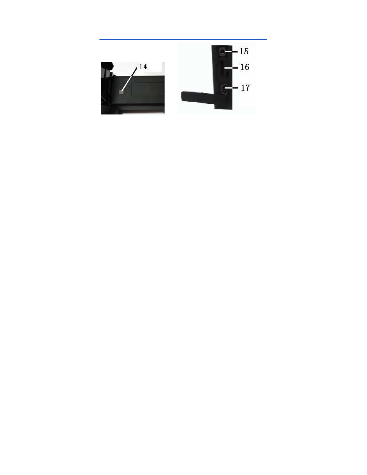
3.2 Side View
14. Power ON/OFF button
Long press this button to power on/ off the device.
15. Multifunctional interface for audio output or video output
Please insert converter cable. It can be connected to headphones to listen
the playback audio notes as analog audio output interface; It can be
connected to the monitor to play videos as a video output interface.
16. SD card interface
MICRO 2G SD card can be inserted into the interface to expand storage
volume.
17. USB Interface
Standard USB interface can be connected to the computer for data
transmission.
Page 15

8
3.3 Bottom View
18. External DC In
External DC requirement is DC 5V.
19. Screw nut on tripod
Size of screw nut on tripod 1/4” _20.
3.4 Left Side View
20. 3.2" Color 270° tiltable LCD
Page 16
9
4. Quick Start Reference
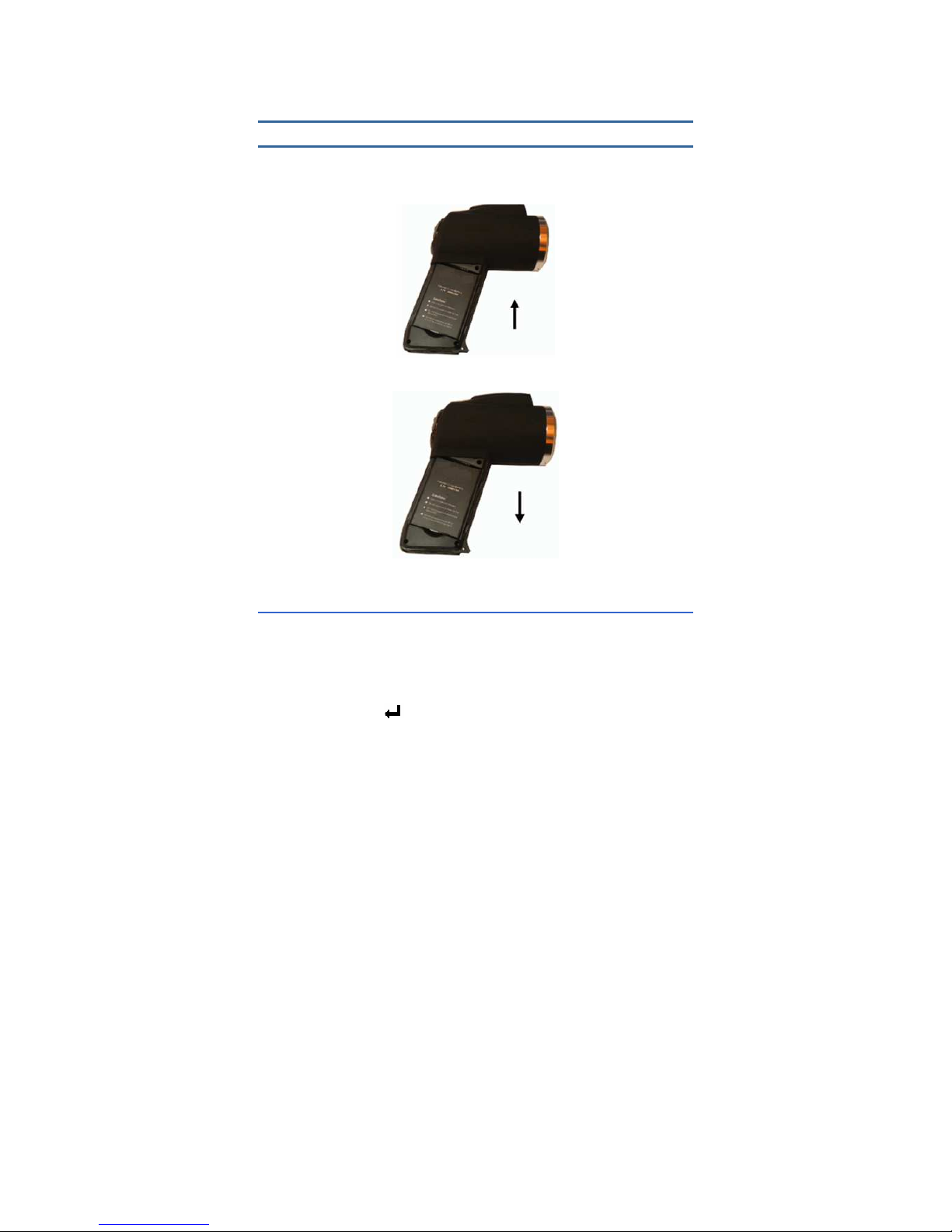
4.1 Battery Setting
Insert and move in the lithium battery as indicated direction, user can
easily insert and move the battery.
Battery Installation
Battery Removal
4.2 Quick Operations
Insert the battery correctly.
Long press Power button until the LED light is on, and wait until
system finishes initialization.
Slide IR Lens lid down, point to target, and adjust focus to get crisp
thermal image.
Long press the button to rectify thermal image.
Page 17

10
4.3 Measure Target Temperature
Point device to measurement target, and press HotKey button 1 to
auto-focus. On the upper-right LCD corner, *=×× displays the spot
measurement result. For better accuracy, long press button to
perform manual rectify.
Select Area (Rect) Measurement to measure max, min, and average
temperature within a rectangle box.
It is recommended to press button to freeze thermal image first,
and then apply different and detailed analysis. Press button one
more time to unfreeze.
When measure result is outside standard temperature range, screen
display changes to indicate either below or above temperature range.
E.g.: 175/395 is with -20 ~ 250
℃℃℃℃
, then the Camera Will Display>
250.0
℃℃℃℃
or <-20.0
℃℃℃℃
to Prompt Users.
4.4 Infrared Image and Voice Annotation
Each thermal image can save up to 40 seconds voice annotation
data. Image and voice annotation can later be reviewed on PC by
bundled IRSee software. To save infrared image, press the Shutter
button while accessing the target image, then a “Voice” dialog box
appears, select “Cancel”, then press the Enter key, the image file
has been saved; select the “Record”, then press the Enter key, both
image and voice files have been saved.
In main menu, press the Enter key to File Save provides the same
function.
: Select Cancel during voice recording to exit.
4.5 Infrared Image Playback
Press the Enter button to enter the main menu.
Select the Main Menu → File → Manage, and then select the file
directory and file name, the thumbnail image of the stored image is
displayed, then press the Enter button to enter the viewing state.
When viewing thermal image, press the Left ( ) or Right ( ) button
to switch thermal image in the same folder.
Page 18
11
The icon indicates voice annotation attached to current thermal
image. Press Enter button to enter File → Voice, then select “Play”
to play back.
Long press the Enter button to return the real-time imaging mode.
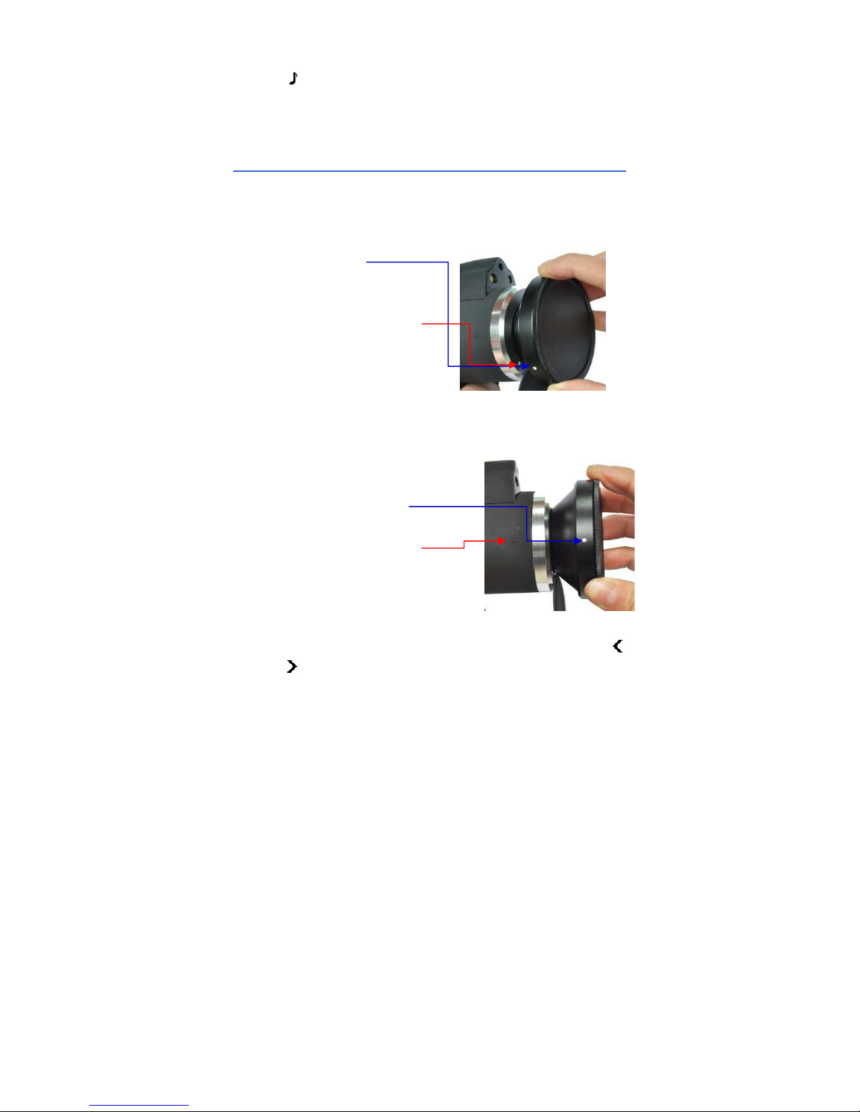
4.6 Telephoto and Wide-angle lens
The device can be equipped with telephoto lens or wide-angle
lens. Put lens in accord with the dots (Figure 1) in line, then turn lens
in clockwise direction till to the two dots in line (Figure 2).
Figure 1
Figure 2
Enter →Image→ Analysis Setting →IR Lens menu, press the
or button to adjust the corresponding lens.
The dot on the lens
The dot on the device front
part
The dot on the lens
The dot on the device
body
Page 19
12
Operate Image Save and Image Playback according to the steps
mentioned in 4.4 and 4.5 here in above.
4.7 Connect to PC
Connect device to PC using included USB cable. it’s available to to export,
delete, and format the data saved in the built-in FLASH memory or on the
SD card.
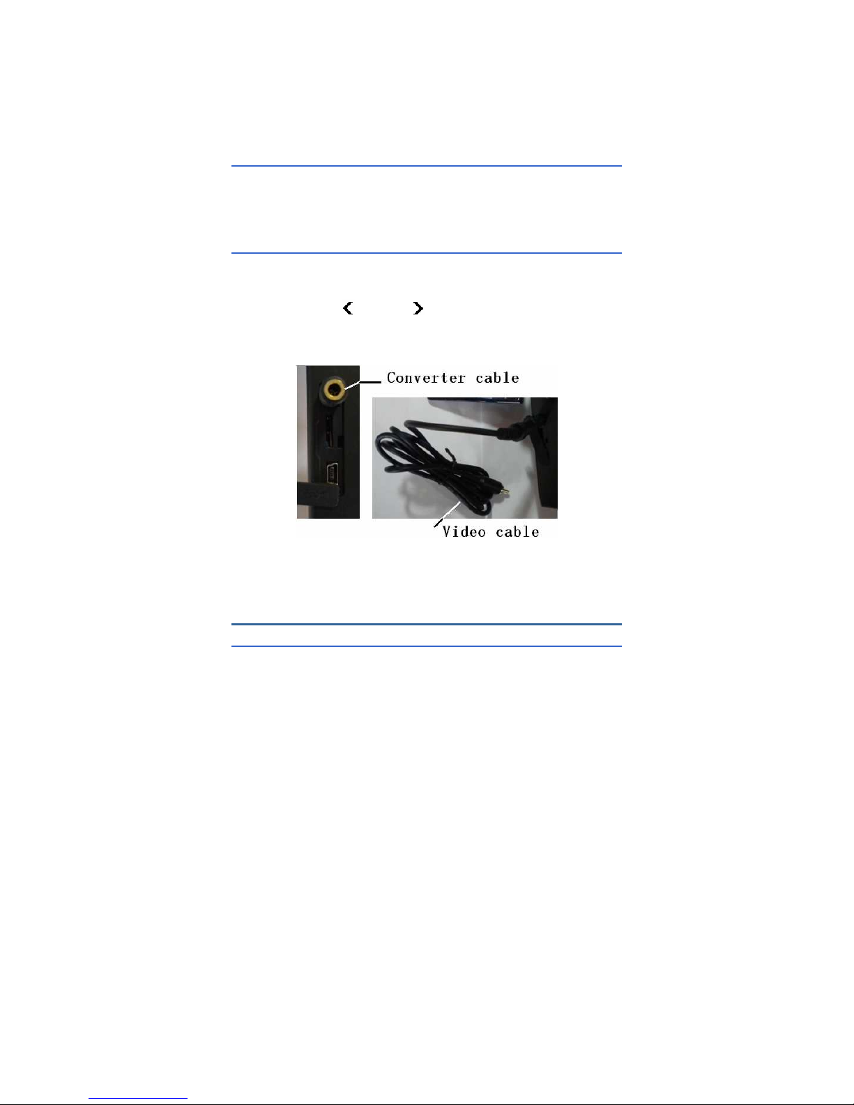
4.8 Video and Audio output
Insert Converter cable to Multifunctional interface for audio output or
video output, connect Monitor to Converter cable using Video cable,
Enter → Setup → System Setup → Display Device,
Press the Left ( ) or Right ( ) to switch to Monitor in the Display
Device, then get thermal image in the Monitor.
Insert Converter cable to Multifunctional interface for audio output or
video output, then insert Common earphone to Converter cable,
finally tune voice annotation according to 4.5.
5. Operation Menu
5.1 Display Summary
All items can be selected by short pressing HotKey 2 button
Page 20
13
(Note: Long press Hotkey 2 button will turn on/off laser sight). The
selected item is flashing in yellow color. If no operation in 2 seconds after
selection, Hotkey mode will exit automatically.
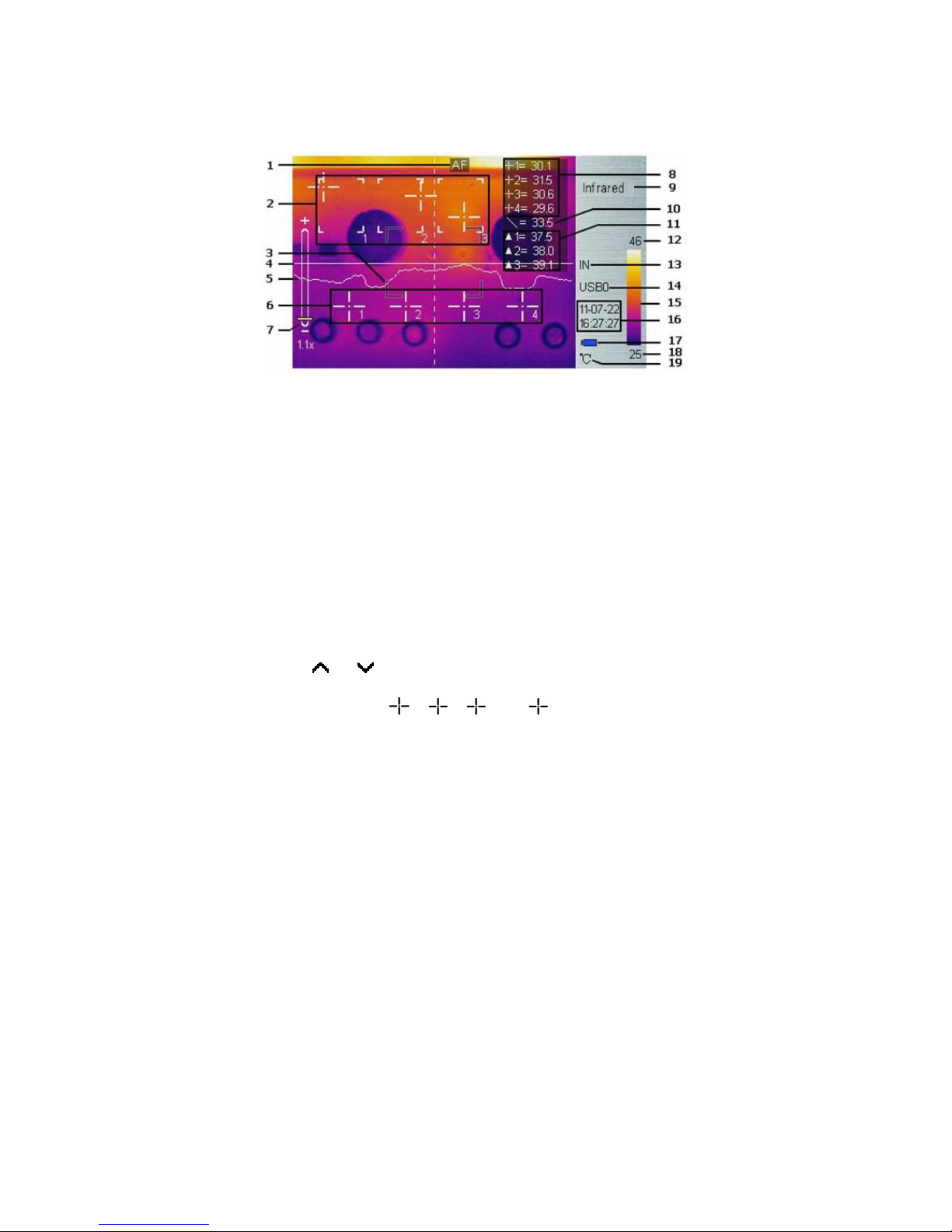
Real-time Thermal Image Interface
1. Auto-focus: Press Hotkey 1 button for auto focus.
2. Area Measure Box: 3 areas can be selected in area measure box;
enter the Main Menu → Measure → Rect to operate.
3. AF Area: objects need focused can be displayed in the area to
achieve Auto focusing effect.
4. Horizontal measuring line: Horizontal sampling line, Enter the Main
Menu → Measure → Line to select the function.
5. Temperature distribution curve: sample temperature distribution
curve of the measure line.
6. Point measure cursor: 4 measure points can be selected. Enable
the Main Menu → Measure → Spot to operate.
7. Symbol for 1-8X digital zoom: display the multiple of digital zoom,
under the real-time measurement mode or the preview mode, click
the or key to change infrared images step-by-step in the
multiple of 0.1.
8. Point measure:
1, 2
,
3
and 4 indicates temperature
value of point 1, 2, 3 and 4 respectively.
Page 21

14
9. Imaging mode: Infrared, visual, fusion, PIP, and Superpose can be
switched by pressing the or button.
10. Line measure: the temperature value in the crossing of measure line
and cursor line.
11. Area measure: measure points within the area (maximum, minimum
or average temperature is optional)
12,18. Lower or upper limit temperature: the lower and upper limit
temperature of the color code at the same time.
13. Storage medium: IN indicates built-in FLASH, SD means SD card;
enter the Main menu → Setup → System Setup → Storage
Medium to adjust the storage medium.
14. USB symbol: USB0 means file transmission, USB1 means video
transmission; enter the Main menu → Setup → System Setup →
USB to switch.
15. Color Code: color palette. Any kind of color code is available in
the palette.
16. Time Display: it displays the default date and time.
17. Battery condition: indicates current battery power condition.
19. Temperature unit: there are three options: 、、K. enter the Main
Menu → Image → Analysis Setup →Temp unit to switch.
5.2 Main Menu
Menu and sub-menu items:
Page 22
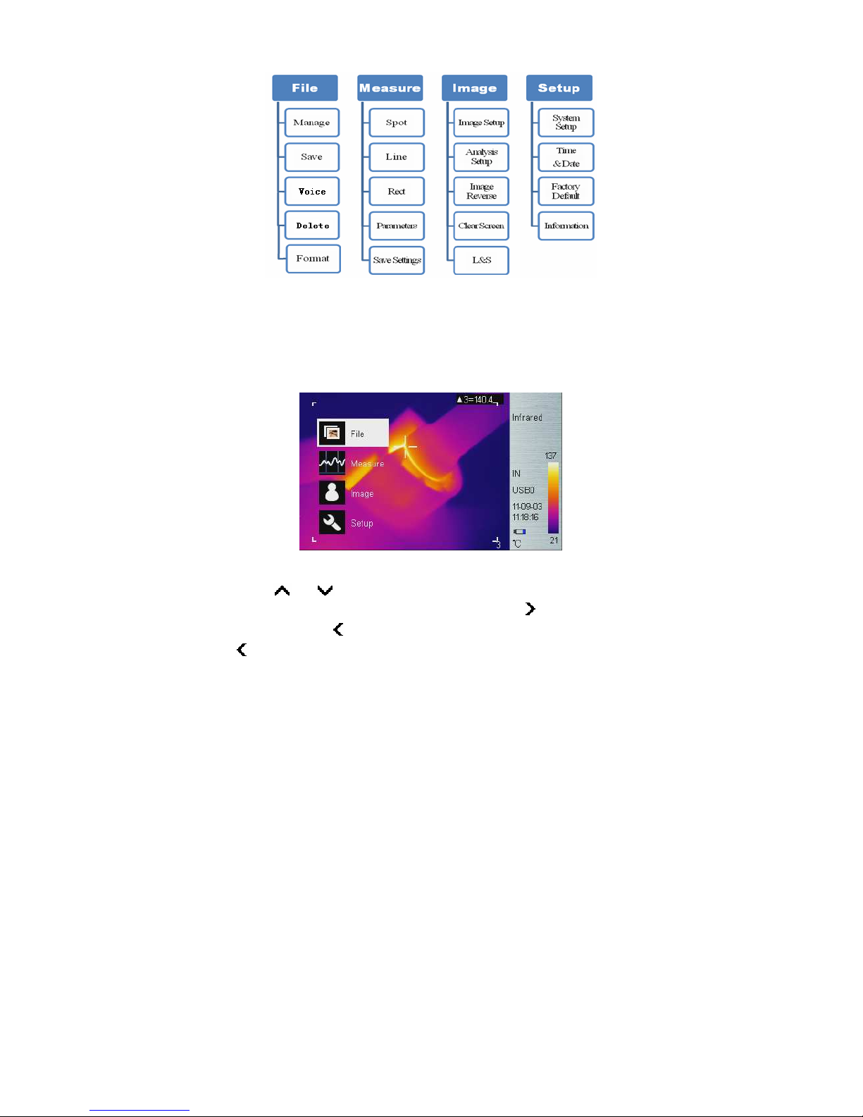
15
Enter the Main Menu:
Long press Enter button (when not in Hotkey mode) to enter main menu
as shown below, not if press Enter button too long, instead of enter main
menu, triggers manual rectify.
Main Menu
Using or button to select menu item, and selected item is
highlighted with white background. Press Enter or button to enter
sub-menu, press button to return to the previous menu or exit. (The
key is unavailable to switch under a sub-menu consisting of left or right
switchable options).
Page 23
16
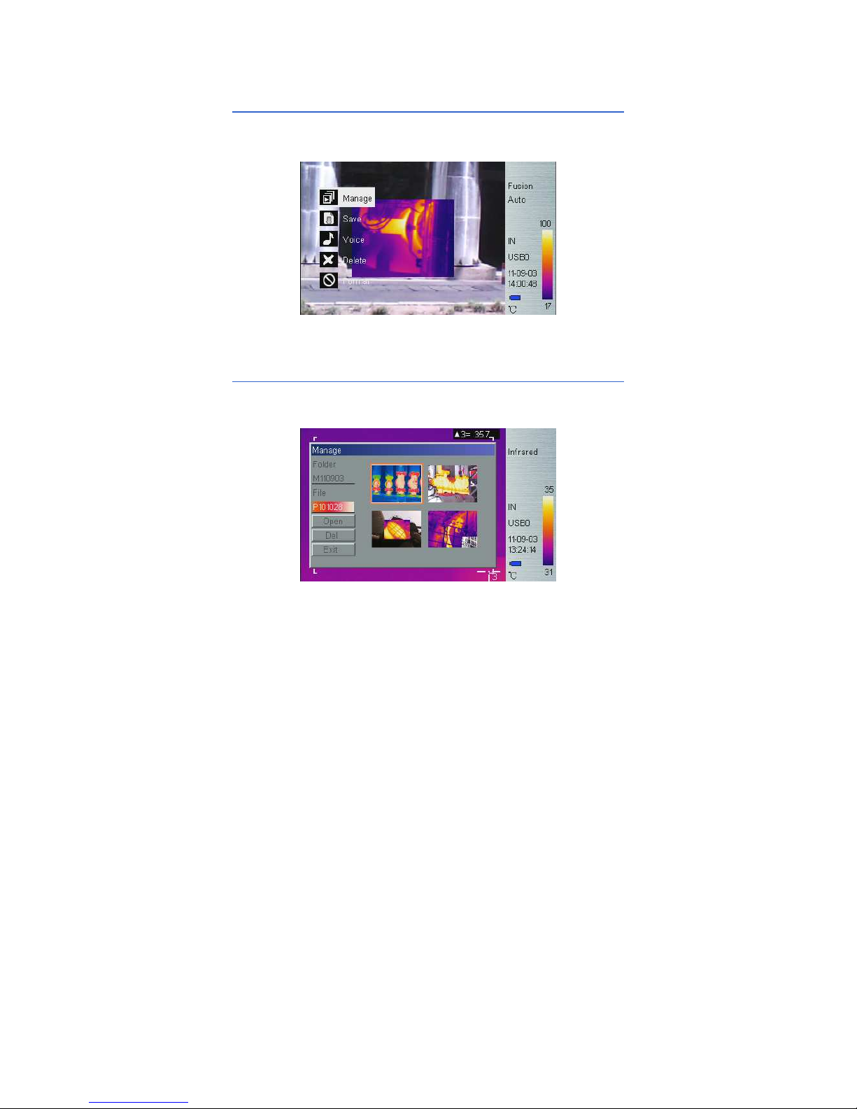
5.2.1 File
Using File menu to save, playback, and delete thermal image, or add voice
annotation or format disk.
File Sub-menu
Manage
Select Manage to preview thermal image, add or edit voice annotation, or
delete thermal image.
File Manage
Folder is automatically created if not exist when saving thermal image.
Folder name is MYYMMDD, and YYMMDD is year, month, and date. For
example, Jan 2nd, 2009 folder is M090102. All thermal images taken in this
day is saved in this folder. Thermal image file name is Phhmmss, and
Page 24
17
hhmmss is hour, minute, second (according to system time). For example,
P080502 in folder M090102 means the thermal image taken at 8:05:02
time in Jan 2nd, 2009.
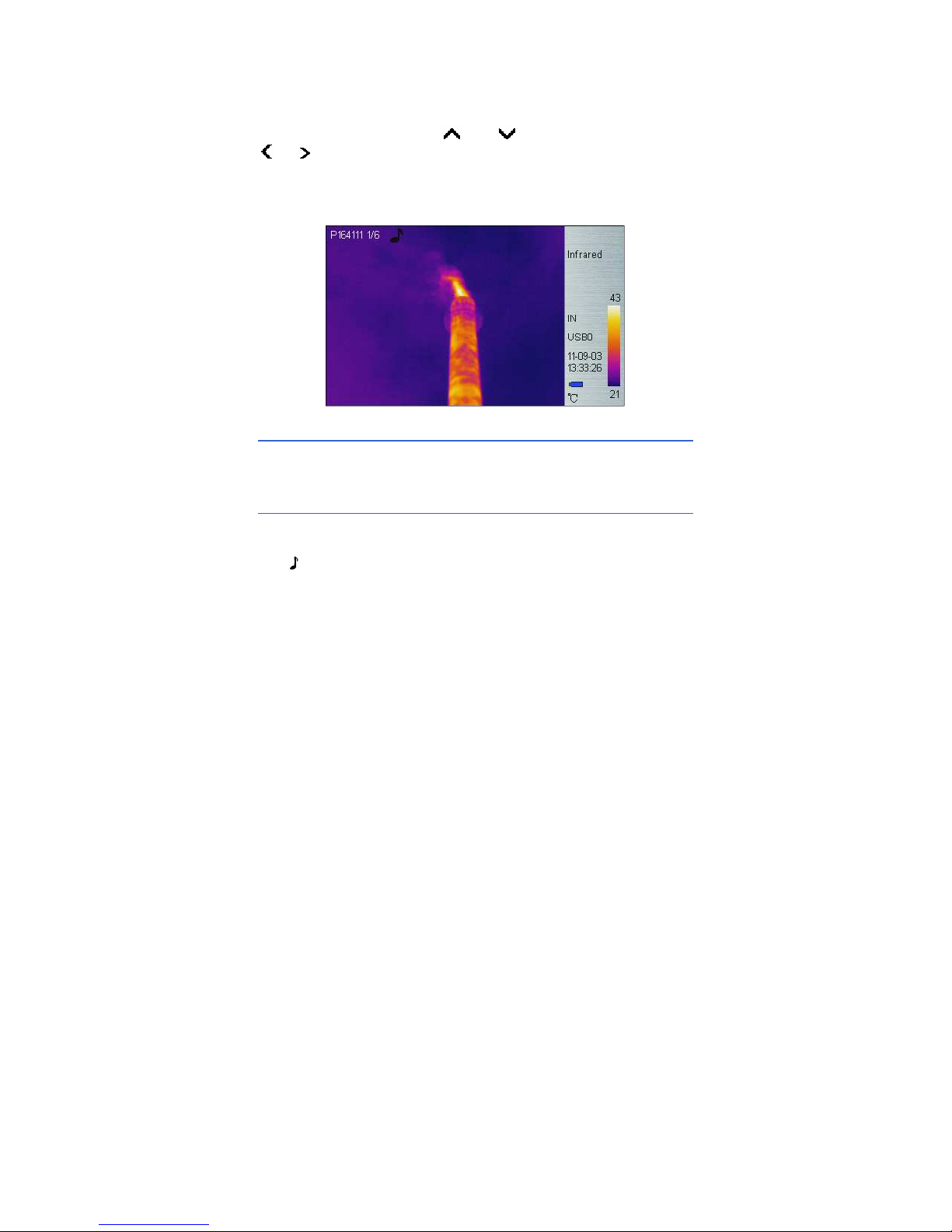
In File Manage window, press and button to select items. Press
or button to switch folder or file when highlighted. After selecting
thermal image, press Enter key to Open to view thermal image or press
Enter key to delete it, and press Exit to exit File Manage window.
Thermal Image preview
Save
Save real-time thermal image. The operation method is the same as
Shutter button.
Record & Play
The Voice menu is used for recording, playing back, save and cancel
operations.
The icon indicates voice annotation data with current thermal image. If
voice annotation already exists, press Record will record new voice
annotation and erase previously saved one. Press Cancel first to stop
recording then press Save to save.
Page 25
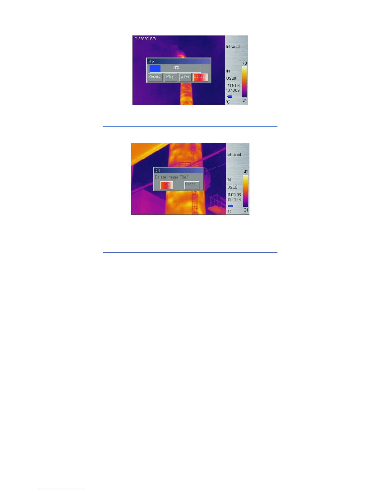
18
Voice Annotation
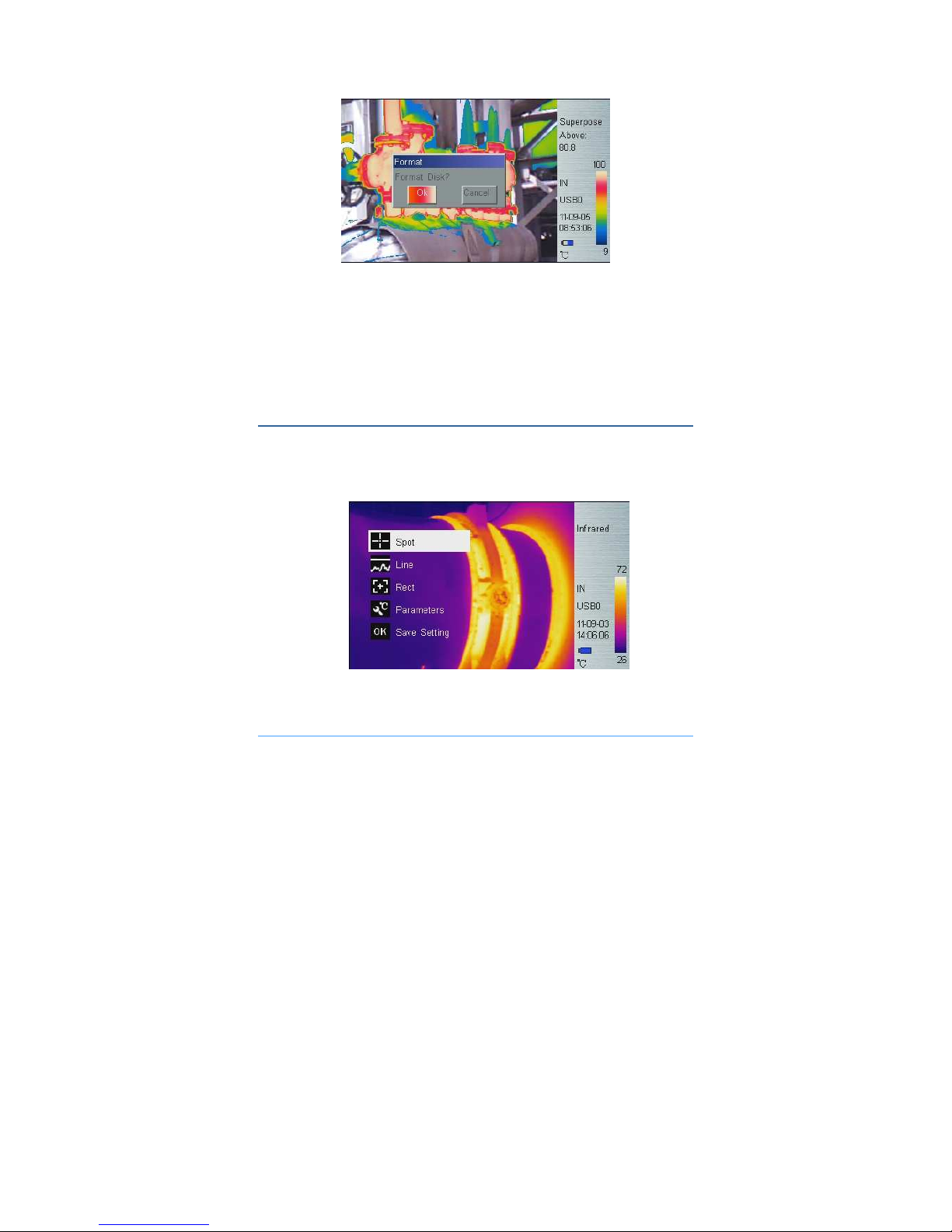
Delete
Enter the delete menu, a dialog box pops up prompt, select the “Ok”
option and press the Enter key to delete the thermal image.
Delete saved thermal image
Long press the Enter key to exit the preview mode.
Format
Format the built-in FLASH or SD card. When Press Enter button to Main
Menu → Setup → System Setup → Storage Medium to select the
“Internal”, then format the built-in FLASH; to select the “SD” to format the
SD card. After the option is selected, a dialog box pops up prompt
“whether to format the disk?” press the “Ok” option to immediately format
saved data, press “Cancel” option to exit.
Page 26
19
Format saved thermal image
: Once FLASH or SD card is formatted, all saved data will be
permanently deleted, please ensure that the data has been transferred to
PC before format.
: If the system fails to save images, please search and kill viruses, and
if no virus is found, please backup data before formatting.
5.2.2 Measure
There are 5 items: Spot, Line, Area (Rect), Parameters, and Save Setting
in Measure menu.
Measure Sub-menu
Spot Measure
Page 27
20
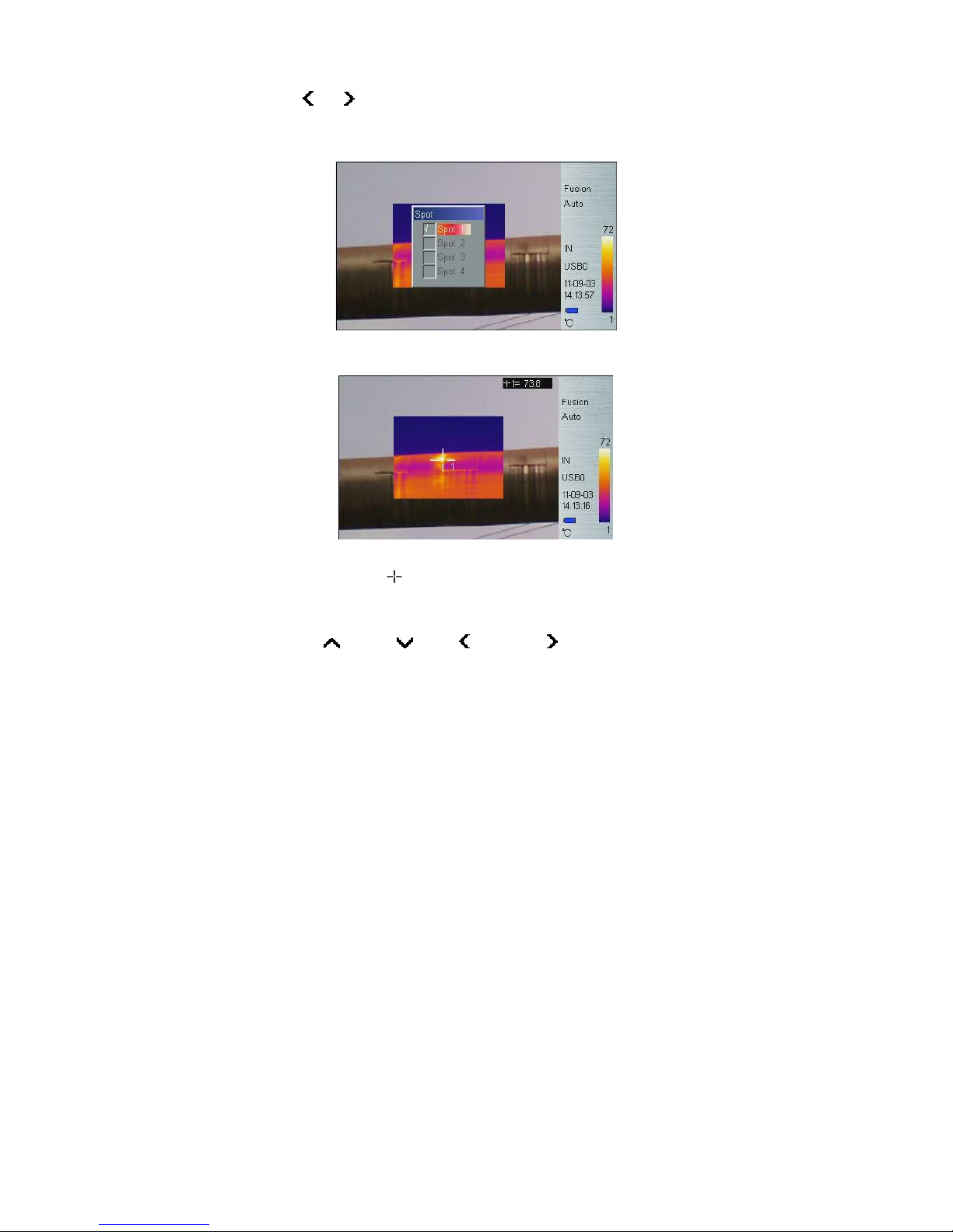
Press or button to select or deselect. Selected spot is check
marked. Up to 4 spots can be selected at the same time.
Spot Target Selection
Spot Measure
Measure result on upper-right LCD corner is temperature reading at
location marked with . Up to 4 spots can be selected.
Spot Measure Attribute
Press Hotkey button 2 until spot marker is flashing in yellow, and then
press Up ( ), Down ( ), Left ( ) and Right ( ) buttons to move spot
location to different directions, press Enter button to enter Attribute Menu
to set the emissivity and reference point. After 2 seconds with no operation,
system will exit to real time Infrared view screen.
Page 28
21
Spot Measure Attribute
Emissivity: Refer to Appendix Emissivity of raw materials.
Set Reference: Set current spot as reference point. If selected, all
measure result will be relative value to this spot temperature.
Line Measure
There are 2 line measure options: vertical and horizontal.
Horizontal Line Measure
Horizontal Line Measure
Horizontal line is temperature sampling line, and upper-right LCD corner
displays temperature measurement reading on vertical cursor line
intersection. After using HotKey button 2 select line measure, press
and button to adjust sampling line position, and press and
button to adjust cursor line position. Press Enter button to enter Attribute
Menu. After 2 seconds with no operation, system will exit to real time
Infrared view screen.
Page 29

22
Horizontal Line Measure Attribute
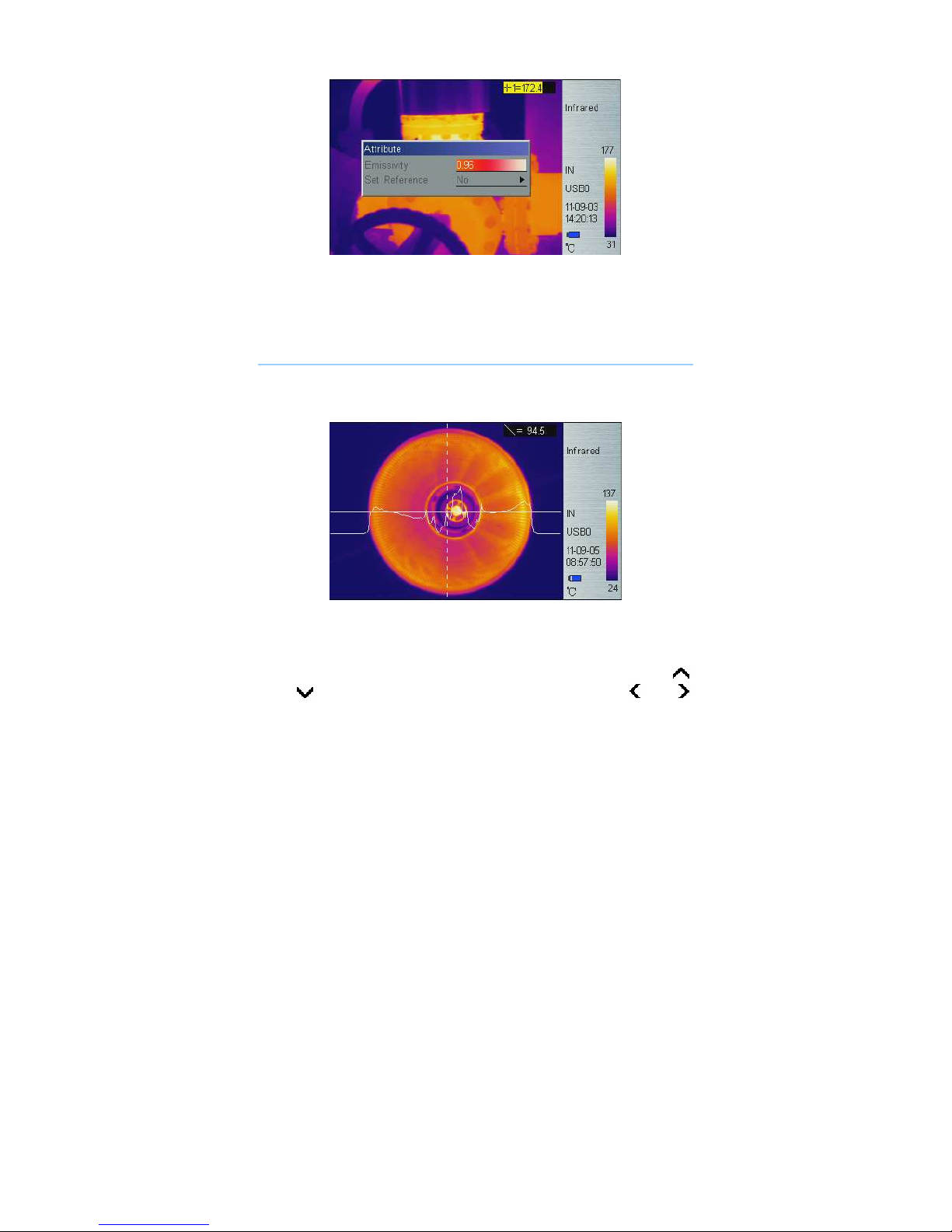
Vertical Line Measure
Vertical Line Measure
Vertical line is temperature sampling line, and upper-right LCD corner
displays temperature measurement reading on horizontal cursor line
intersection. After using HotKey button 2 select line measure, press
and button to adjust sampling line position, and press and
button to adjust cursor line position. Press Enter button to enter Attribute
Menu. After 2 seconds with no operation, system will exit to real time
Infrared view screen.
Page 30

23
Vertical Line Measure Attribute
Area (Rect) Measure
Press and button to select or deselect. Selected Area is check
marked. Up to 3 areas can be selected.
Area (Rect) Target Selection
Area (Rect) Measure
Measure result on upper-right LCD corner is the temperature
Page 31

24
measurement result within the corresponding rectangle. There are 3
measure types: max, min, and average temperature.
Area (Rect) Measure Attribute
Press the HotKey button 2 until area rectangle is flashing in yellow. Press
Enter button to enter Attribute Menu in which four parameters can be
adjusted namely: emissivity, set reference, measure type, move /size.
Area (Rect) Measure Attribute
Emissivity: Refer to Appendix: Emissivity of raw materials.
Set Reference: Set current area as reference. If selected, all measure
result will be relative value to this temperature.
Measure Type: Select from max, min, and average.
Adjust: Adjust rectangle position and size.
Parameters
Change different settings to adjust temperature measurement accuracy.
Press and button to select different parameters, and press
and button to change value.
Page 32

25
Parameter Sub-menu
Emissivity
Emissivity varies based on target subject material, surface temperature,
surface roughness, measurement angle, and etc. Press or once to
change Emissivity by 0.01. Long press or will change Emissivity in
0.1 intervals.
Distance
This value can be omitted if target subject is close to device (less than
10m). Otherwise, set Distance value accordingly to get more accurate
temperature reading. Press or once to change Distance 0.1m.
Long press or will change Distance in 1m interval.
Humidity
This value can be omitted if target is close to device (less than 10m).
Otherwise, set Humidity value according to environmental condition. Press
or once to change Humidity 1%. Long press or will change
Humidity in 10% interval.
Adjust Ratio
Due to long time usage of device, the sensitivity of IR detector may
decrease. In such case, it is necessary to adjust ratio value to get more
accurate temperature reading. During calibration, if temperature reading is
higher than actual target temperature, change ratio value lower, and vise
versa. Press or once to change ratio value 0.01. Long press or
will change ratio value in 0.1 intervals.
Adjust Temp
Under certain condition, it is necessary to adjust temperature reading by a
Page 33

26
pre-define value. Normally this option should be left unchanged. Press
or once to change 0.1. Long press or will change this value
in 1 interval.
Save Setting
All parameter changes must be saved before power off device. Otherwise,
changes will not be saved for next power on.
5.2.3 Image
There are 5 items: Image Setup, Analysis Setup, Image Reverse, Clear
Screen, and L&S (Auto/Manual) in Image Menu.
Image sub-menu
Image Setup
Page 34

27
Image Setup Sub-menu
Alarm Switch
Press or turns on or off the alarm function. If the Alarm Switch is
on, when target subject within area box has surface temperature over
Alarm Temp, device will alarm with buzzer sound and mark the high
temperature location as Alarm Color if Alarm Color is set.
Alarm Temp
When Alarm Switch is off, this option is disabled. When Alarm Switch is on,
Alarm Temp is the desired alarm temperature. Press or once to
change Alarm Temp 0.1. Long press or will change Alarm
Temp in 1 interval. Default setting is 37.0.
Alarm Color
Alarm Color can select as: Auto, Black, White, Red, Orange, Yellow,
Green, Blue, Gray, and Purple. Default setting is Auto, which is no color
alarm.
Isotherm Color
When this option is Auto, there is no Isothermal display. Otherwise, target
subject Infrared image will change to selected color when temperature is
within the range of (Isothermal Temp ± Isothermal Width/2). Default setting
is Auto.
Isotherm Temp
Page 35

28
Press or once to change Isothermal Temp 0.1. Long press or
will change Isothermal Temp in 1 interval.
Isotherm Width
Adjust Isothermal Width to change the range of Isothermal Color display.
Press or once to change Isothermal Width 0.1. Long press or
will change Isothermal Width in 1 interval. Default setting is 1.0.
Hot Superposition
Overlay infrared image partly on visual image, which is convenient to
identify and analyze infrared image.
There are 3 modes to setup target area to infrared image, the other area to
visual image.
Press or button to select Above, Below, Interval of thermal
superposition.
Interval: If select Interval type, it is necessary to set the upper limit
of interval and lower limit of interval; Press or to change 0.1,
Long press or to change in 1 interval.
Infrared image overlays visual image between two specified
temperature.
Above: if select Above type, it shall adjust above temperature level;
Press or to change 0.1, Long press or to change
in 1 interval.
Infrared image overlays visual image above specified temperature.
Page 36
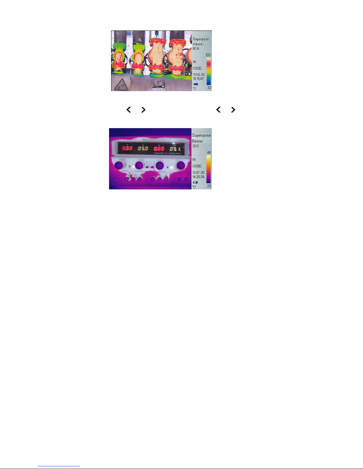
29
Below: If select Below type; it shall adjust below temperature level;
Press or to change 0.1, Long press or to change
in 1 interval.
Infrared image overlays visual image below specified temperature.
Thermal Superposition Attribute
In Superpose mode, Press Hotkey button 2, the interval area is flashing in
yellow, then press Enter button to pop up dialog box, it is available to
adjust Superposition Type, Upper limit of interval, Lower limit of
interval, Above temperature, Below temperature.
Page 37

30
Thermal Superposition Attribute
Fusion
Scaling infrared image overlaying visual image, the fusion has 4 types:
automatic, 1 / 2 Fusion, 1 / 4 Fusion, and 3 / 4 Fusion.
automatic
Page 38

31
1 / 2 fusion
1 / 4 fusion
3 / 4 fusion.
Page 39
32
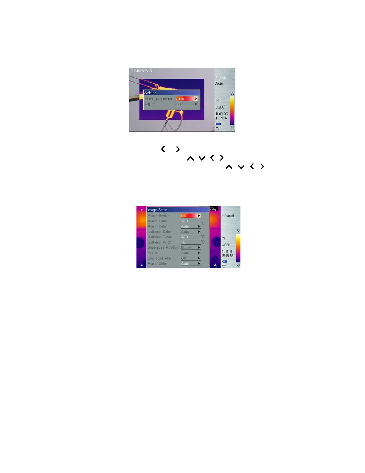
Fusion Attribute
Under thermal fusion mode, press Hotkey button 2 to switch until the word
“Fusion” is flashing in yellow, then Press Enter button to pop up dialog
box,to set Fusion Mixing Ratio, Position / Size. After 2 seconds with no
operation, system will exit to real time Infrared view screen.
Fusion Attribute
Mixing proportion: press or to set Auto, 1/2, 1/4, 3/4 mode.
Adjust: select Size to confirm, press , , , buttons to adjust
fusion box’s size; select Position to confirm, press , , ,
buttons to adjust fusion box’s position. After 2 seconds with no operation,
system will exit to real time Infrared view screen.
Dew point alarm (available only for 170/390)
Page 40

33
Dew point alarm: press or button to turn on/off dew point alarm
function. If the Alarm Switch is on, manually adjust the current ambient
temperature and humidity, the corresponding dew point temperature can
be indicated on the lower left corner of screen; if the dew point
temperature value exceeds the preset temperature, device will alarm with
setting alarm color.
Alarm Color
Alarm Color can select as: Auto, Black, White, Red, Orange, Yellow,
Green, Blue, Gray, and Purple. Default setting is Auto, which is no color
alarm.
Dew point temperature shown on lower left corner
:dew point temperature can be defined as a temperature of air cooled
to saturation in the case that both the water vapor content and pressure
in air are consistent, which is related to ambient temperature and
humidity.
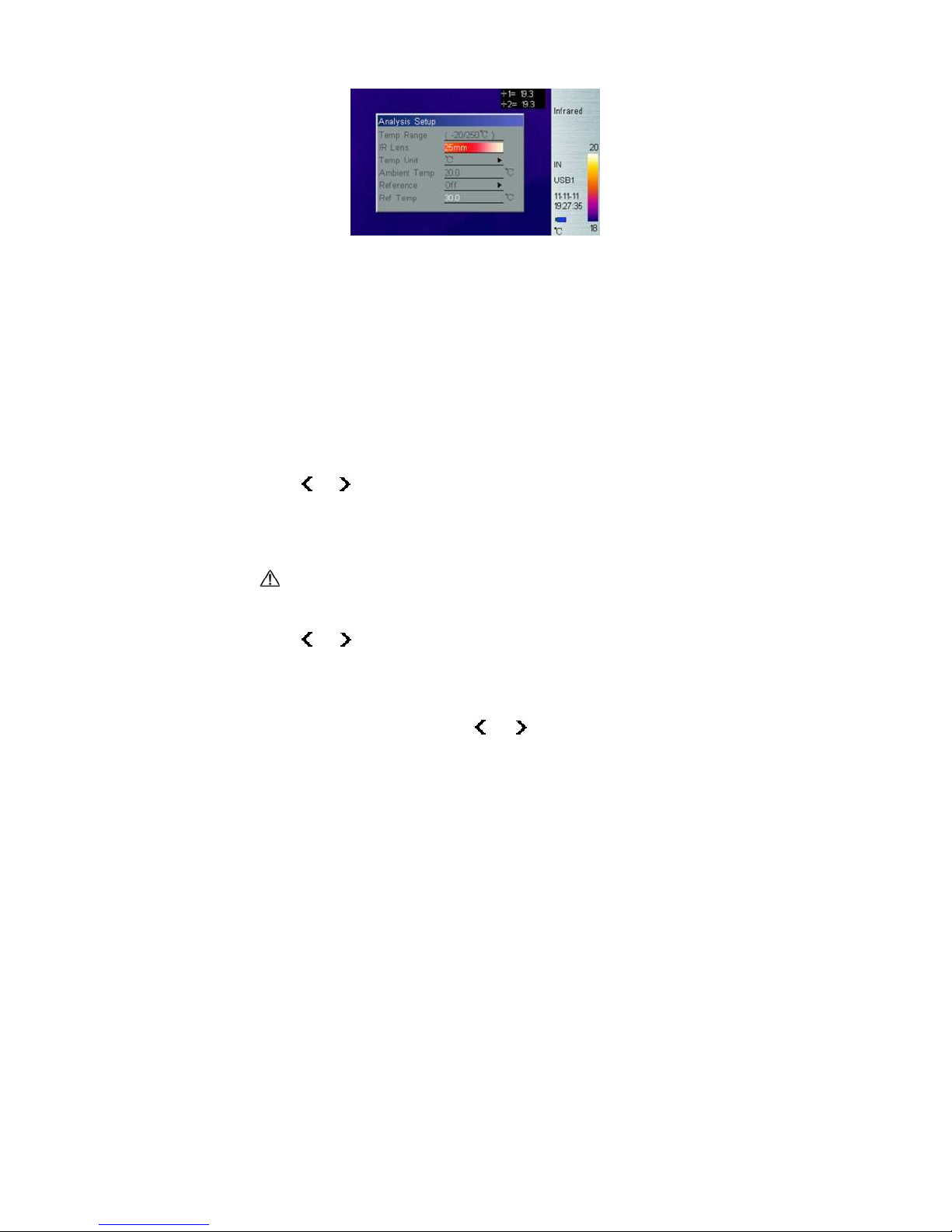
Analysis Setup
Page 41
34
Analysis Setup Sub-menu
Temp Range
Select Temp range base on measure target temperature.
175/395 standard Temp range is -20℃ to 250℃, extra temp range
(200℃/600 ℃) or temp range (200℃/1200℃) is customized service.
170/390 temp range is only from -20℃ to 100℃.
IR Lens
For 170/175 infrared camera, there are 3 options: 11mm (standard lens),
5.5mm (wide-angle lens), and 22mm (telephoto lens);
For 390/395 infrared camera, there are 3 options: 21.5mm (standard lens),
11mm (wide-angle lens), and 40mm (telephoto lens).
Press or button to select correct IR lens for best measurement
result after installing optional IR lens, for example, if remove wide-angle
lens / telephoto lens from device, the device is with standard lens, please
set “11mm” or “21.5mm”.
The camera may need 20 seconds to readjust a new lens before it
can work properly.
Temp Unit
Press or to select Temperature Unit from , , and K.
=9/5*+32,K=273.15+
Ambient Temp
For more accurate measure result, set Ambient Temp to correct
environmental temperature. Press or once to change Ambient
Page 42
35
Temp 0.1. Long press or will change Ambient Temp in 1
interval.
Reference
Set reference spot or area to display measure results as relative value.
Ref Temp
Press or once to change Ref Temp 0.1. Long press or
will change Ref Temp in 1 interval. This option is only active when set
Ref Temp as reference.
Image Reverse
Press Enter button to reverse palette for thermal image display. Press
Enter again to switch back.
Clear Screen
Press Enter button to clear all items at thermal image area.
L&S (Auto/Manual Mode)
Press Enter button to switch between auto and manual rectifying. In
manual rectifying mode, upper-left corner of LCD display shows L&S, and
press or to adjust upper temp limit and lower temp limit.
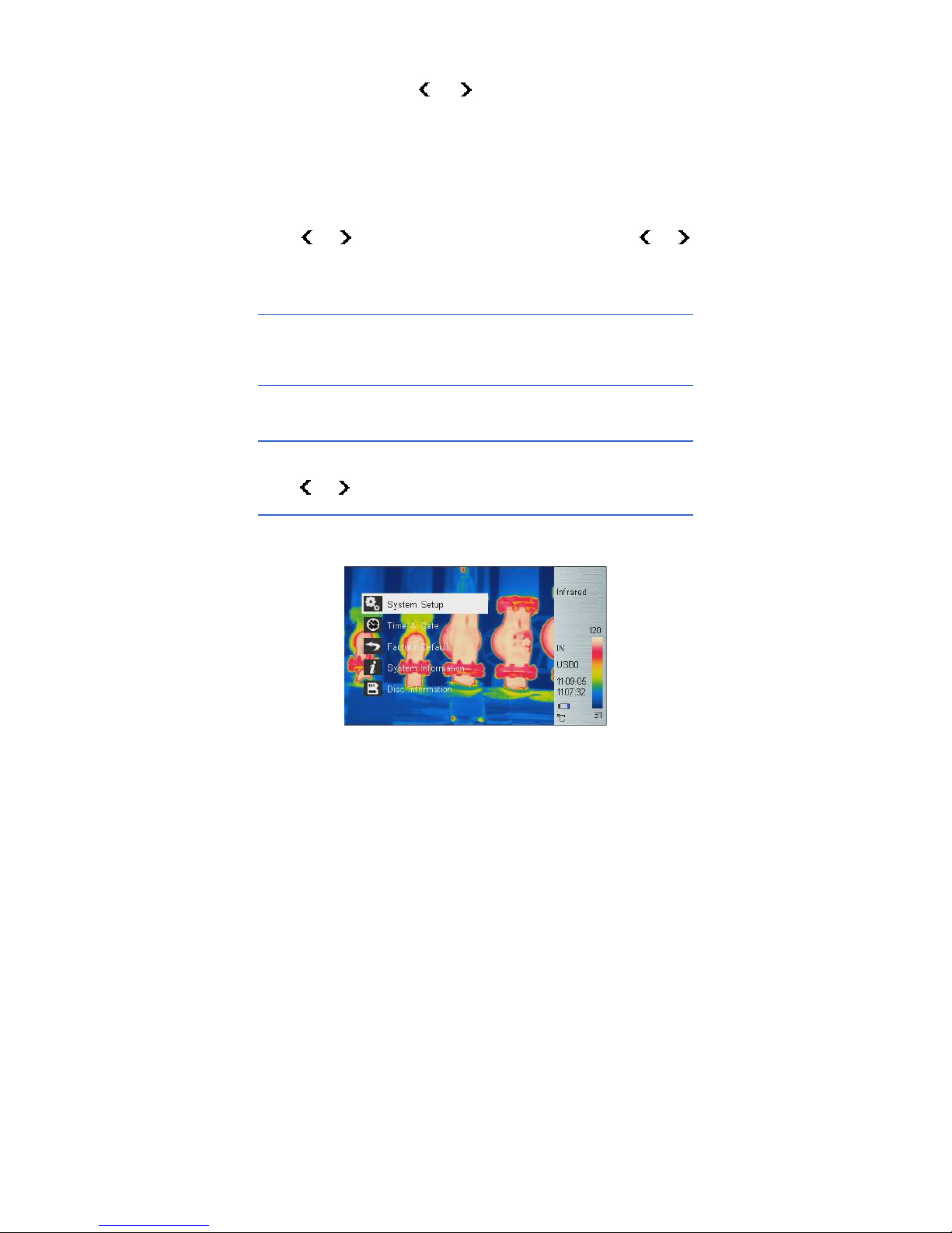
5.2.4 Setup
There are 5 items in Setup menu: System Setup, Time & Date, Factory
Default, System Information and Disc Information.
Setup Sub-menu
Page 43

36
System Setup
There are 10 options in System Setup menu: Language, Auto Rectify,
Auto Save, Video, Transparence, Display Device, Screen Save, Power
Save, USB, and Storage Medium. Press and button to switch
selection, press and button to adjust value, active item is
highlighted with red background.
System Setup Sub-menu
Language
There are 11 different language options: Simplified Chinese, Traditional
Chinese, English, Korean, Japanese, German, French, Russian, Italian,
Portuguese and Spanish.
Auto Rectify
Set the number of seconds to perform next auto-rectify. Set value between
1 and 3000 seconds. Value 0 means disabling auto-rectify feature.
Auto Save
Set the number of seconds to perform next auto-save. Set value between
7 to 3600 seconds. Value 0 means disabling auto-save feature. Press
or once to change the value by 1 second. Long press or will
change the value in 10 intervals.
Video
Select between PAL and NTSC.
Page 44

37
Transparence
Set to enable or disable menu transparence feature.
Display Device
Select between LCD display and external monitor device. Only one video
output device can be selected at one time, the other one will be disabled.
: If accidentally selected external monitor device and LCD display is
disabled, power off and power on device to get LCD display back.
Screen Save
Set the number of minutes without operation to trigger disabling LCD
display to save power. Select between 5min, 10min, 30min, and None.
Power Save
Set the number of minutes without operation to trigger power off
completely. Select between 10min, 20min, 30min, and None.
USB
File Transmission and Video Transmission, press or button to
switch options. If select File transmission, device is used as a U disk to
export, delete, or format the data saved on the built-in FLASH or SD card
to PC; If select Video, device is used to transmit the real-time video
images to PC via IRSee software.
After set up ‘ IRSee Report ’ Suite and USB device condition to video
mode, the USB device can be used as a camera for infrared and visible
light. For example, click the video connection key and after a while, the
video conversation will be achieved via MSN, Skype, QQ etc. when the
video source is only from Thermal Imaging Camera. If the sources are two
or more, please choose ‘TIUSB’ among device names and the device
names can pop up after pressed video connection key.
Storage Medium
Storage Medium includes Internal and SD card, press or button to
switch options. The capacity of Built-in FLASH is 256M, the capacity of
Page 45
38
standard SD card is 2G, and the disk format is FAT.
:
Device only identify FAT format SD card, not any other format .
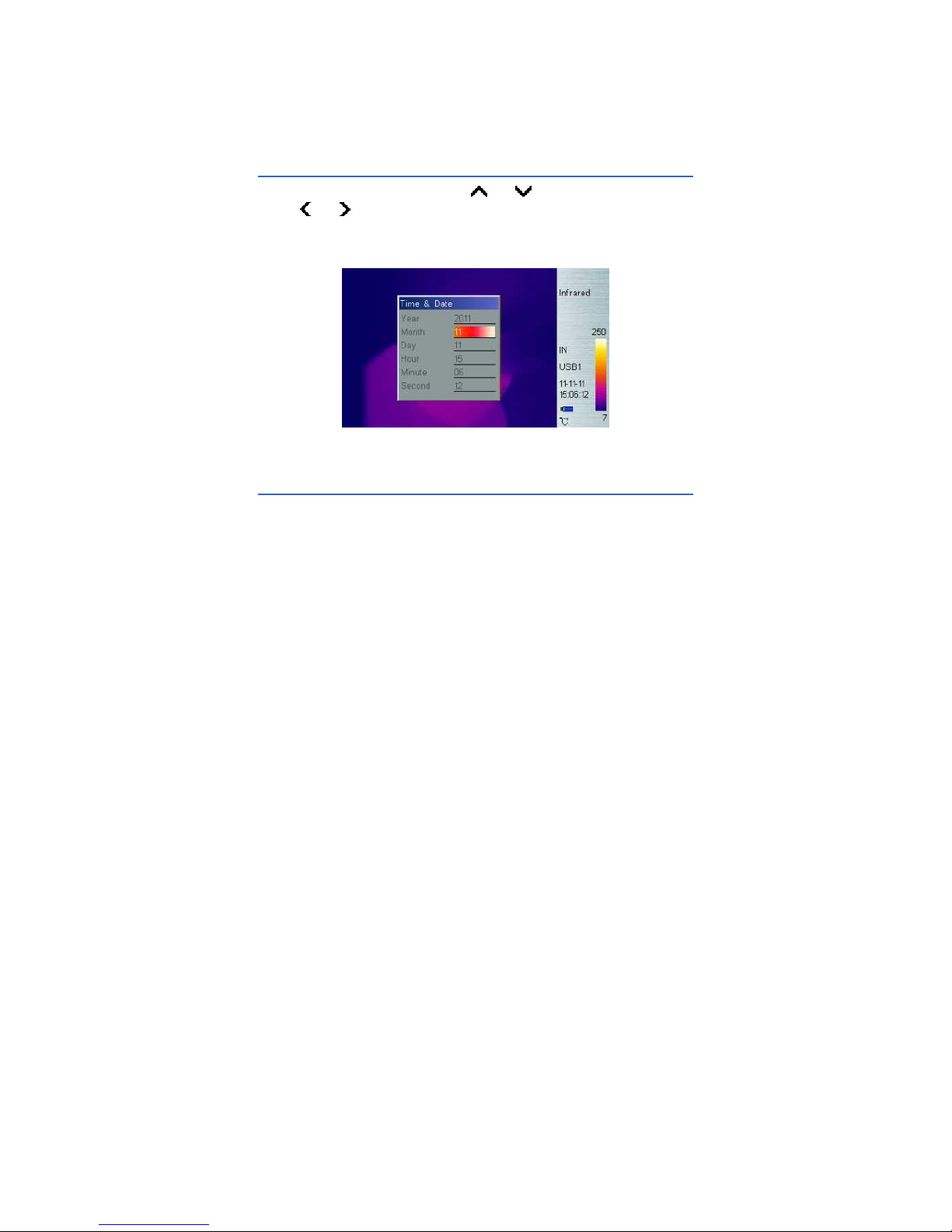
Time & Date
Set system date and time. Press or button to select an item,
press or button to change its value and press Enter button to
confirm. If Li-Ion battery is removed for a long time, it is necessary to reset
system time and date.
Time Setting
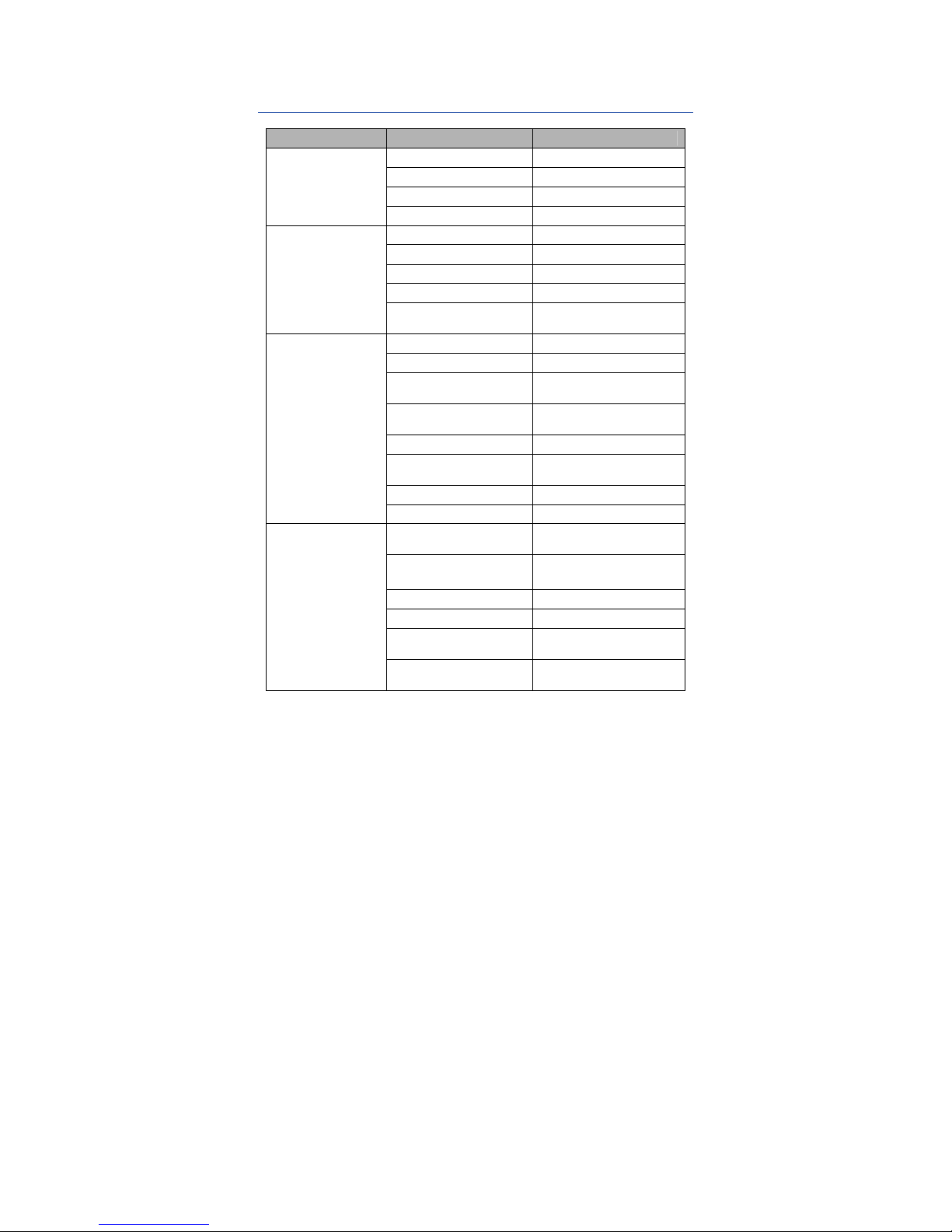
Factory Default
Restore factory default and rectify some improper settings.
Page 46
39
Parameters List of Default settings
Items
Parameters
Value/function
Spot 1、2、3、4
Disenabled
area 1、2
Disenabled
area 3 enabled
Measured Target
Measuring line None
Emissivity 0.96
Distance 1.5
Humidity 60
Correction factor 1.00
Measurement
Parameters
Correction
temperature
0.0OC
Alarm Disenabled
Alarm temperature 37.0 OC
Alarm color,
isothermal color, etc.
Auto
Isothermal
temperature
37.0 OC
Isothermal height 1.0 OC
Thermal
superposition type
Interval
Fusion Auto
Image Settings
Dew point alarm Disenabled
Temperature range
170/390:-20/100 OC
175/395:-20/250 OC
Lens
11mm(170/175)
21.5mm(390/395)
Temperature unit
O
C
Ambient temperature Manual
Reference
measurement
Disenabled
Analysis Settings
Reference
temperature
30.0 OC
Page 47
40
Continued: Parameters List of Default settings
Items Parameters Value/function
Languages English
Automatic correction 150S
Automatic storage 0S
Video format PAL
Menu Transparency Enabled
Display Mode Screen
Screen Auto-close
None
USB File transmission mode
System Settings
storage media Flash
Time Settings Time No change
System Information
Select to display system information, such as: serial number, software
version, and production date etc.
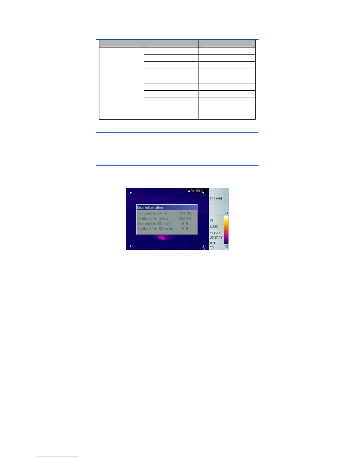
Disc Information
Select to display Disc Information as follows: the dialog box can indicate
the FLASH’s used disc space and free space, as well as used space, free
space of SD card.
Disc Information
Page 48

41
6. Building Thermal Imaging Summary
As the quality of life improves and the low-carbon life style becomes
known, higher demands are being set on buildings. The features of our TI
series IR camera make it possible to detect slight temperature difference
and to analyze indoor humidity and leakage. Hereinafter are images in
some cases.
The effect drawing of building detection
The effect drawing of indoor humidity
Page 49

42
The effect drawing of indoor pipe heat leakage
The effect drawing of indoor corner air leakage
Page 50

43
7. Technical Specifications
Continued::::Technical specifications
Type New UFPA micro-bolometer
170/175 160×120
Resolution
390/395 384×288
IR
Detector
Pixel Spacing
25µm
170/175
21°×16°/0.1 m
Standard Lens
390/395
21°×16°/0.4 m
170/175
Wide-angle :42°×32°/0.1 m
Telelens :10°×8°/1 m
Optional Lens
390/395
Wide-angle :38°×28°/ 0.3 m
Telelens :11°×8.5°/1.2 m
170/175
2.3mrad
Spatial
Resolution
390/395
1.2mrad
170/175 0.05, 30
Thermal
Sensitivity
390/395 0.065, 30
Frame-frequenc
y
50/60Hz
Focusing Auto/Motor
170/175
0.1 continuous stepping zoom
within 1-4 multiples
Digital Zoom
390/395
0.1 continuous stepping zoom
within 1-8 multiples
Spectral Range
8~14µm
visible camera
2Mpixel
Image
Quality
spotlight YES
display 3.5" Color 270° tiltable LCD
Display
Image modes
Thermal、visual、thermal fusion、
picture-in-picture、thumbnail gallery
170/390
-20 OC~+100 OC
Temperature
Range
175/395
-20
O
C~+250
O
C (Standard)
+200 OC~+600 OC(Optional A)
+200 OC~+1200 OC(Optional B)
Accuracy
±2 OC or ±2%(reading range), select the
bigger value
Measure
rectification
Auto/Manual
Measure
Measure Mode
4 spots, 3 areas available under real time
mode(max, min and average temp) line
measure, isothermal display, temp difference
measure and temp alarm (sound/color)
Page 51

44
Color Palette
12 Colors selectable (including iron red,
rainbow, black-white, and white-black
etc.)
Image Setup Auto/Manual adjust contrast, brightness
System Setup
Date, Time, Temperature Unit ℃/℉/K
10 Languages available, namely:
Chinese (simplified & traditional),
English, Italian, Japanese, Russian,
French, German, Korean, Spanish and
Portuguese.
Emissivity
Rectification
Adjustable from 0.01 to 1.0
Ambient Temp
Rectification
Auto, according to background
temperature input
Atmospheric
Trans
Correction
Auto, according to distance, relative
humidity, ambient temperature input
Measure
Dew point
alarm
Available only for 170 and 390
175 Up to over 700 images
Storage Media
(Built-in
Memory)
395 Up to over 500 images
175 Up to over 5600 images
2G Micro SD
395 Up to over 4000 images
Storage Mode Auto/Manual single frame image storage
File Type JPEG, with 14 bits measure data
Storage
Voice Annotation
40 Seconds voice recording
per image (built-in microphone)
USB
USB File download, video transmission
Laser
Director
Class 2, 1mW/635nm Red
Battery Type Rechargeable Li-Ion Battery
Battery Operating
Time
3 Hours (Under normal temperature)
Charging type Intelligent charger
Power Save Included
Power
Supply
External Power 5V±5% DC
Operation
Temperature
-20℃~ +50℃
Operating
Condition
Storage
Temperature
-40℃~ +60℃
Page 52

45
Humidity
≤90% (non condensing)
Protection Grade
IP50
Weight 480g
Physical
Size (L×W×H) 128×62×154mm
8. Technical Support
For common mistakes and issues during operation, please refer the
following form. If issue cannot be resolved, please contact our technical
support department.
For simple problems arising during operation, please refer to the following
table. If the problem cannot be settled, please cut off the power and
contact our technical department.
Problem Cause and Solution
Camera cannot be
powered on
No battery or batteries are not installed
correctly → Install battery correctly.
Battery power is used up.
→ Change battery or recharge.
Save power mode
→power on after 5 seconds.
Device power off
automatically
Battery power is used up.
→ Change battery.
Battery power is soon
used up
Ambient temperature is too high or low.
Battery is not fully charged.
→ recharge battery fully.
Battery may already reach end of life.
(300 usage cycles)
→ use new battery to charge.
No thermal image
Lens lid is closed.
→ Remove lens lid.
Thermal image is black
and white
Black & white palette may be selected.
→restore factory default.
Page 53

46
Failures Causes and Solutions
The infrared camera can
not start
The battery is uninstalled or improperly
installed
Insert the battery; or re-install the battery.
The battery runs out
Replace or charge the battery.
infrared camera auto- shutdown
Wait 5 seconds and then restart.
The infrared camera shuts
down automatically
The battery runs out
Replace the battery.
Battery power runs out
fast
Ambient temperature is too low or too
high.
The rechargeable battery is not fully
charged
Recharge the rechargeable battery.
The life of battery is almost over, about
300 cycles of charge and discharge for
the type of battery
Replace rechargeable battery
no thermal image
displayed
Lens cap is not open → open the lens
cap.
thermal image turns black
& white
Check if black and white color code is
selected → reload default settings.
Page 54

47
9. Appendix: Emissivity of Raw Material
(For reference purpose only)
Material Surface Temp (
O
C
)
Emissivity (ε)
inoxidized 100 0.20
Aluminum
Oxidized 100 0.55
Brown polished 20 0.40
Unpolished 38 0.22
Brass
Oxidized 100 0.61
Copper Oxidized badly 20 0.78
Oxidized 100 0.74
Iron
Rusted 25 0.65
Oxidized 200 0.64
Cast Iron
inoxidized 100 0.21
Rough 25 0.94
Wrought
Iron
Polished 38 0.28
Nickel Oxidized 200 0.37
Stainless
Steel
Oxidized 60 0.85
Steel
800℃ Oxidized
200 0.79
Brick -- 20 0.93
Concrete -- 20 0.92
Glass Smooth flat 20 0.94
White 100 0.92
Lacquer
Natural Black 100 0.97
Smoky black 25 0.95
Candle smoke 20 0.95
Carbon
Black-lead rough 20 0.98
Paint 16 Color average 100 0.94
Paper White 20 0.93
Soil -- 20 0.90
Wood Polished 30 0.90
Water -- 30 0.96
Skin Human 32 0.98
Fine 21 0.90
China
Rough 21 0.93
Page 55

1
Uncooled Focal Plane Infrared
Cameras
IRSee Report Software
User Manual
Page 56

i
Table of Content
Ⅰ. Software Installation....................................................................1
1. Introduction ...........................................................................1
2. System Requirements...........................................................1
2.1 Hardware Configuration................................................1
2.2 Operating System.........................................................1
3. Software Installation..............................................................1
4. Uninstall Software.................................................................3
5. Start Software .......................................................................3
Ⅱ. Function Description ...................................................................5
1. Image Import and Export ...................................................5
1.1 Image Import.................................................................5
1.2 Image Export.................................................................5
2. Modules................................................................................6
2.1 Quick Access Toolbar...................................................6
2.2 Ribbon...........................................................................7
2.3 Measuring Temperature Zone.....................................17
2.4 Histogram Area...........................................................24
2.5 Line Profile Measurement Area...................................26
2.6 Color Code Area ......................................................... 27
2.7 Label Area...................................................................28
2.8 Visible Light.................................................................30
Page 57

ii
Disclaimer
1. Limited Liability
Software does not guarantee the quality, performance or
applicability of any hidden special purpose.
The contents of this manual will be updated because of device
upgrade or other various reasons. Our company reserves the right
to edit this manual without further notice.
2. Quality Assurance
The quality administration system of this product during the
process of R&D and production has been approved in accordance
with ISO9001 standard.
3. Compatibility with Previous Versions
This IRSee Software version supports all file and data created by any
IRSee Software version.
4. Compatibility with Infrared Camera
This Software supports all JPEG format image recorded by
Infrared Camera.
Page 58

1
Ⅰ
ⅠⅠ
Ⅰ. Software Installation
Welcome to Use IRSee software.
1. Introduction
The IRSee Report version has a friendly user interface, 4 methods for
measure analysis, and the function to save analysis report in Word, PDF,
Excel and other formats.
2. System Requirements
The files of the IRSee software consist of IR image, visual image and
graphic file, all of which are far bigger than normal text files, thus the
following standards of the computer hardware configuration should be
met:
2.1 Hardware Requirements
CPU PENTIUM ® Dual-Core 2.0GHz processor or faster.
1Gbytes or more system memory.
20G or bigger hard disk.
1440×900 or higher resolution screen.
2.2 Operating System
IRSee Software is compatible with Microsoft Windows 2000, XP, Vista,
Windows 7. It provides a multi-language version for users.
3. Software Installation
The instructions of IRSee software installation and necessary precautions
before using this software will be given in detail hereinafter:
Please follow the instructions when installing IRSee software application.
Place software CD-ROM into CD drive, and run setup.exe in the CD root
directory.
The default route is C:\Program Files\IRSee Report. You can change
directory when installing.
Note: users who are operating Vista please close user account control to
prevent warning
Step A: Running the Setup.exe, access the software installation.
Page 59
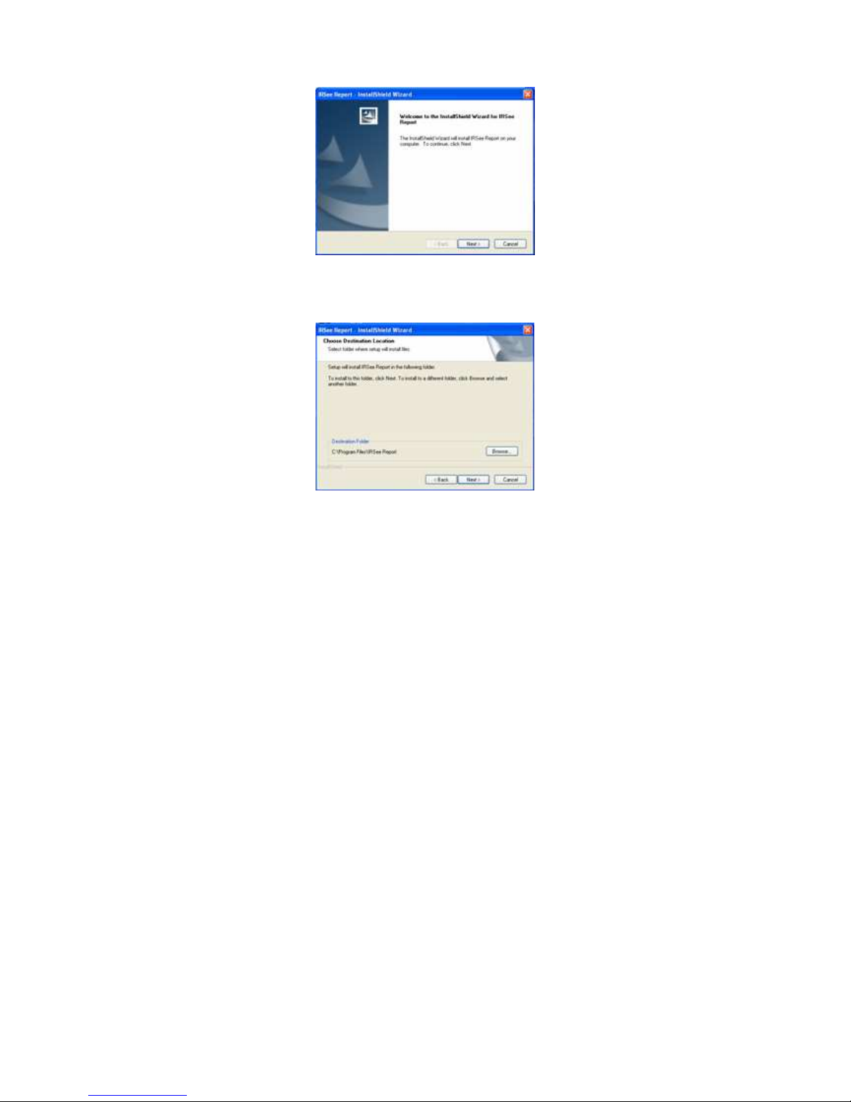
2
Step B:Click the Next button, the system indicates the installation path,
please adjust or change as needed.
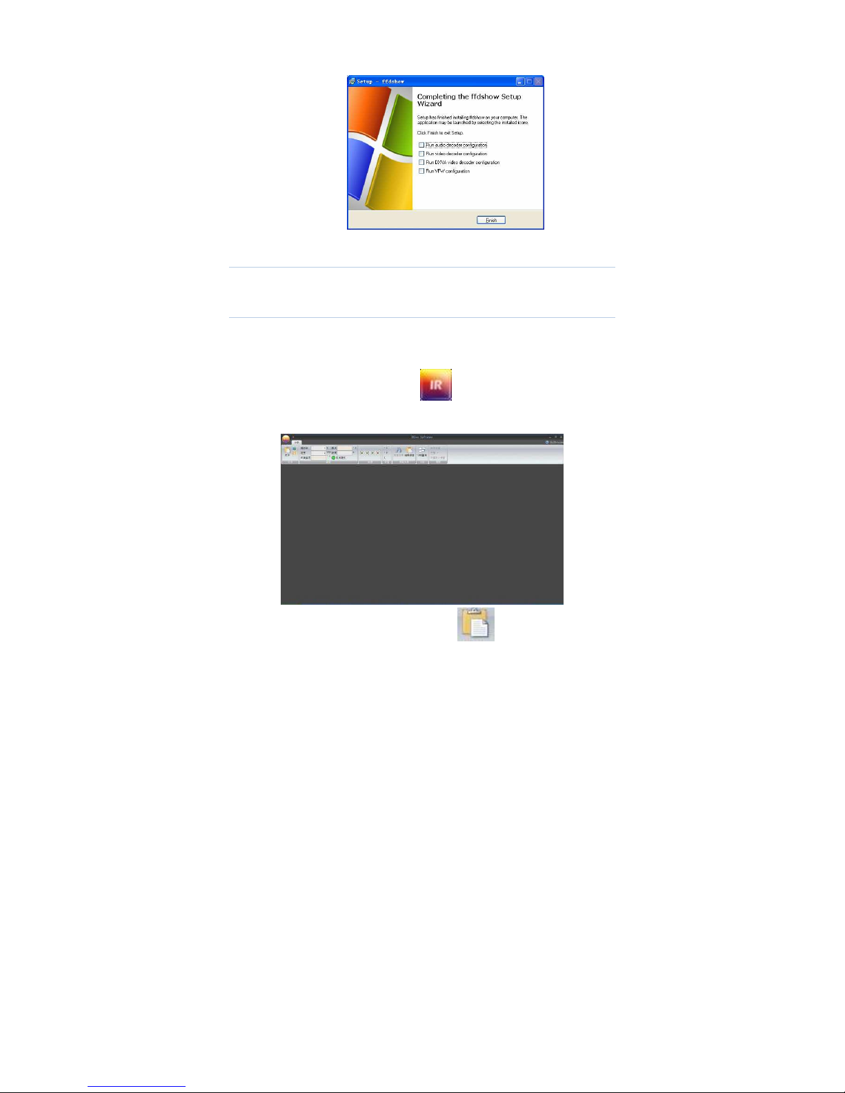
Step C: Click the Next button continuously until the software installation is
completed. The system will enter the encoder installation automatically.
Step D: Click and follow the default installation settings until the installation
is completed.
Page 60
3
4. Uninstall Software
Please select the “Delete” button if want to reinstall the software.
5. Starting-up Software
The following icon appears on Windows desktop after installing
IRSee software.
Double-click the icon and startup IRSee interface.
Open an image by menu: open or icon in the ribbon.
Page 61
4
Note:
IRSee software has 10 different working languages, namely:
Chinese (simplified & traditional), English, Italian, Japanese,
Russian, French, German, Korean, Spanish and Portuguese.
IRSee software has auto-recognition language function with the
operating system in PC, the IRSee will be in English version the
operating system is beyond mentioned languages in PC.
Page 62

5
Ⅱ
. Function Description
Image Import and Export
1.1 Image Import
◆Method 1:
Click the software icon on upper left corner to pop up the menu.
Click the Open button (also available to select a recently opened
image path in the image bar) to pop up the file selection dialog
box.
Select a file in the file selection dialog box (single or multiple
selections available).
◆Method 2:
Click the “Open” button in the ribbon.
1.2 Image Export
It is available to export in accordance with the following methods after
importing images:
◆ Method 1:
Click the “Save As” button on the software icon on the upper left
corner to pop up a file selection dialog box.
Select / a file path and save the image in the current active
window.
◆Method 2:
Click the property analysis in toolbar.
Click the Save As button to pop up a file selection dialog box.
Select / a file path and save the image in the current active
window.
◆Method 3:
Click the software icon on the top left corner.
Click the Save button to save the modified image on the current
active window.
◆Method 4:
Page 63

6
Click the property analysis in Ribbon.
Click the Save button to save the modified image on the current
active window.
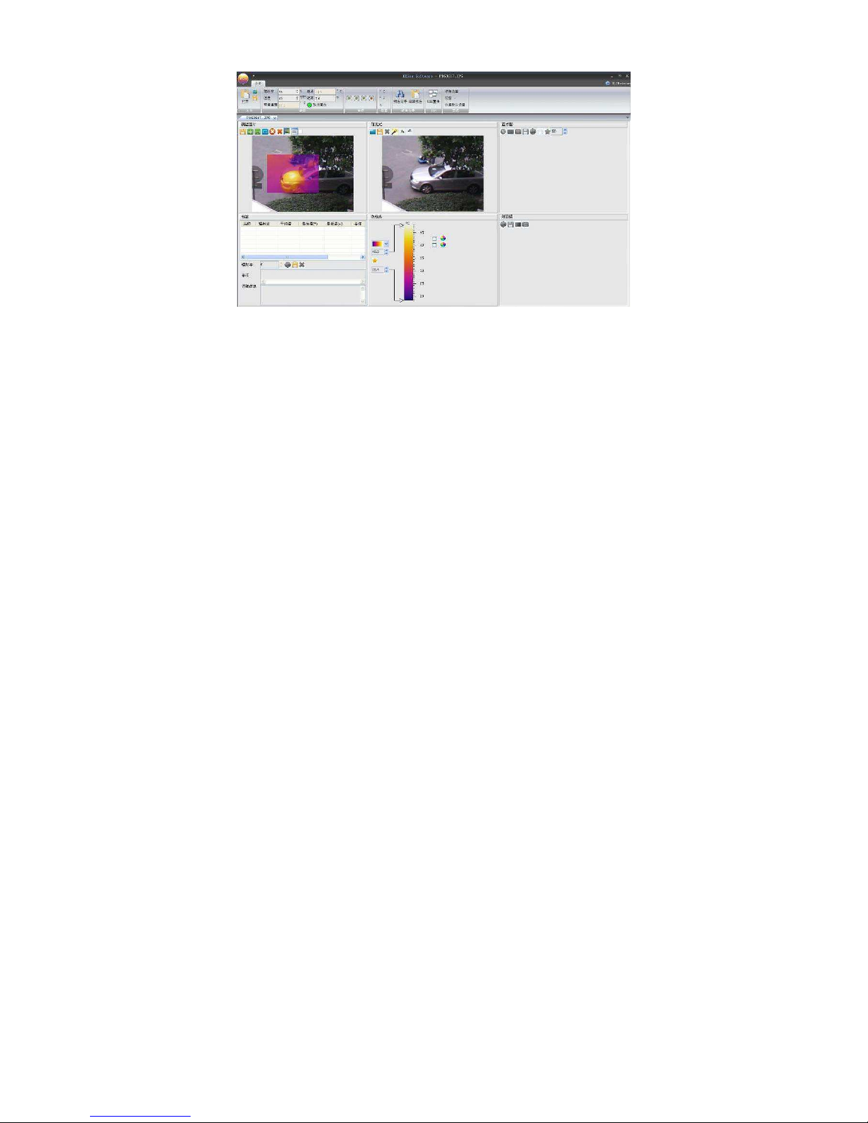
2. Modules
As displayed on the software interface, the software has the follows: the
Quick Access Toolbar, Ribbon, Measuring Temperature Zone, Histogram
Area, Line Profile Measurement Area, Color Code Area, Label Area, and
Visible Area.
2.1 Quick Access Toolbar
Operate the Quick Access Toolbar to customize the buttons in the Ribbon
and the file system, the buttons’ function is consistent with the buttons
shown in corresponding areas.
2.1.1 Customizing the Quick Access Toolbar
Right-click the Ribbon to pop up a menu.
Click the Customize Quick Access Toolbar to pop up customizing
dialog box.
Select the area name in the command drop-down box.
Select your required buttons from the left box and create to the right
box.
It is also available to remove buttons on the right editing box.
2.1.2 Customizing Buttons
Right-click the Ribbon to pop up a menu.
Page 64
7
Left-click Click the Customize Quick Access Toolbar to pop up the
customizing dialog box.
Left-click the Customize button to pop up the Customize Keyboard
dialog box.
Select a type on the upper left type edit box.
Select a button on the upper right command edit box.
Set the button shortcuts in the following two Edit Boxes and
drop-down menu.
Press the Assign button to save the settings.
2.1.3 Position Adjustment of Quick Access Toolbar
Right-click the Ribbon to pop up a menu.
Left-click the Ribbon / Quick Access Toolbar Below, and adjust its
position.
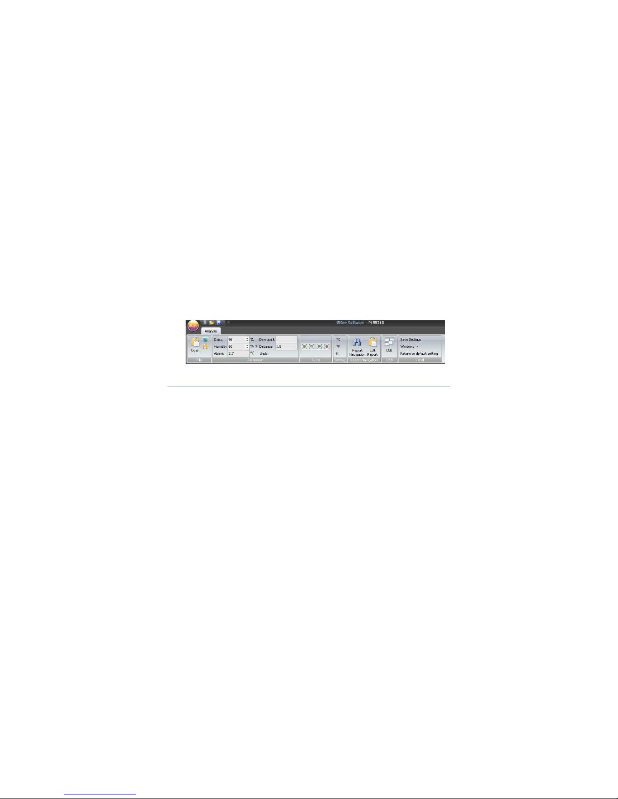
2.2 Ribbon
The Ribbon is composed of File, Parameters, Audio, Temperature Type
Settings, Report Wizard, USB and Panel.
The property analysis interface consists of File, Color, Parameter, Audio,
and Settings, as shown below:
2.2.1 File
2.2.1.1 Open
Click the File button to pop up a file selection dialog box.
Select and open a file to be analyzed in the dialog box.
2.2.1.2 Save
Method 1:
Page 65

8
Click the Save As button to pop up a file selection dialog
box.
Set / select the file path name where the file is saved.
Save the image in the current active window.
Method 2:
Click the File and select the “Save All” button to save all the
modified images.
2.2.2 Set
2.2.2.1 Emissivity adjustment
Method 1:
Please input a required emissivity value (1-100) in the
Emissivity edit box.
Press the Enter key to confirm it.
Method 2:
Click the Up and Down keys in the edit box to adjust and set an
emissivity value.
2.2.2.2 Humidity Adjustment
●Please input a required humidity value (1-100) in the humidity edit box.
●Press the Enter key to confirm.
2.2.2.3 Distance Adjustment
●Please input a required distance value (1-100, unit: meter) in the
distance edit box.
●Press the Enter key to confirm.
2.2.2.4 Ambient Temperature
Select the option to show the actual ambient temperature while the
thermal image is being shot.
2.2.2.5 Dew Point Temperature
Select the option to show the dew point temperature.
Page 66

9
2.2.2.6 Cancel Changes
Click the “Cancel Changes” button to recover the emissivity, humidity,
ambient temperature, or distance to its original state.
2.2.3 Audio
The buttons in audio area are available for the measured image consisting
of audio information only.
Operate the option to play back the audio saved in images.
2.2.4 Set Temperature Type
This option is used to set the temperature display unit, click ℃, ℉ or K to
set the temperature unit to Celsius, Fahrenheit or Kelvin respectively.
2.2.5 Report Wizard
2.2.5.1 Report Wizard
Report Wizard is used for creating a report, the Report Edit is mainly used
for editing a report for further analyze.
Click the Report Wizard to select the type of exported report as needed.
Page 67

10
Click Next to select an image or multiple images.
Fill in related information in accordance with different types of report
templates ->> Preview
Page 68

11
Page 69

12
Page 70

13
Page 71

14
Page 72
15
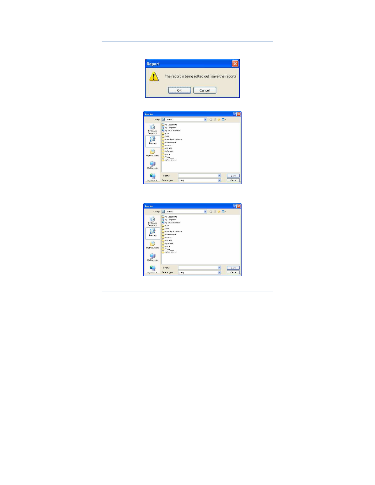
2.2.5.2 Edit Report
If a report is to be closed, the system will prompt whether to save the
report or not.
Click the OK button.
Input and select the saving path and file name, and then click the Save
button.
Click the report in Ribbon ->> Edit Report
Select a saved report to reopen and edit it.
2.2.6 USB Direct-Transmission
Page 73

16
2.2.6.1 Connection
Click the Ribbon Settings ->> USB Direct-Trans
Connect a device, set to USB Direct-Trans mode for the device.
Click the device iron on PC software interface ->> Open the device ->>
Play
2.2.6.2 Video
Click the device ->> Record
Select a video path ->> Input the name of the video file.
2.2.6.3 Stop the video
Click File ->> Stop Recording
Page 74

17
2.2.6.4 Pause, Stop and Close Direct-trans
Click the Pause, Stop and Close buttons under the File menu respectively
to stop the current operation.
2.2.6.5 Print Screen
Click the Print Screen button and save the printed image into the Picture
folder under the installation directory, and name it by a time format.
2.2.7 Panel
It is mainly used for showing/ hiding each area, a user can adjust the size
and position of each display area as needed, and then click the “Save
Settings” to save the current settings, and click the “Reload Default
Settings” to recover.
2.3 Measuring Temperature Zone
The functional options in measuring area are shown below:
The measurement objects can analyze the thermal images by the
following three kinds of analysis methods: point, line, and area.
Page 75

18
Line measurement analysis has three: arbitrary line, horizontal line,
vertical line, and multiple-line analysis is also available.
Area measurement analysis has below: rectangular, elliptical and
polygonal analysis.
The system can analyze up to 20 spots objects, a line analysis object,
20 area analysis objects, 10 polygonal objects and 10 elliptical
objects simultaneously.
2.3.1 Select Measured Objects
The prior sequence of object selection is point, line, and area.
● When two or more objects are simultaneously selected, the system
can operate in accordance with the above prioritization.
e.g.: if both a point object and a line object are simultaneously
selected, the point is more prior than line, the point object will be prior
selected;
If both an area object and a line object are simultaneously selected,
the line is more prior than the area; the line object will be prior
selected.
● If two or more areas are simultaneously selected, the smaller area will
prevail.
e.g.: If Rectangle 1 and Rectangle 2 are simultaneously selected,
Rectangle 1 is smaller than Rectangle 2, Rectangle 1 will prevail.
2.3.2 Point Analysis
Create a point
Click the Create button
Move the mouse to a point to be analyzed, and click it.
Move a point
Move the mouse to a point to be moved.
Page 76

19
When the mouse status changes to , left-click to select the
point.
Move the mouse.
Delete a point
Select a measurement point to be deleted.
Click the button to delete the current measured object.
2.3.3 Line Analysis
Create a line
Arbitrary line
Click the Create button to pop-up a menu.
Click the Arbitrary Line button.
Set a starting point of the line in the thermal image to be
analyzed.
Left-hold and drag the mouse to the terminal point of the line.
Vertical Line
Click the Create button to pop-up a menu.
Click the Vertical Line button.
Set the vertical coordinates of starting point of the line in
the thermal image to be analyzed.
Left-hold and drag the mouse to the vertical coordinates
of terminal point of the line.
Horizontal Line
Click the Create button to pop-up a menu.
Click the Horizontal Line button.
Set the horizontal coordinates of starting point of the line in the
thermal image to be analyzed.
Page 77

20
Left-hold and drag the mouse to the horizontal coordinates of
terminal point of the line.
Move and change a line
Move
Move the mouse to the position of a line to be moved.
When the state of mouse becomes , left-click to select it.
And then move it.
Change the positions of starting point / terminal point
Move the mouse to the position of the line to be moved.
When the state of mouse becomes , left-click to select the
line.
Move the mouse to the position of starting point / terminal point
to be moved.
When the state of mouse becomes , left-click to select
starting point / terminal point.
Drag the mouse to the required position of starting point /
terminal point.
Delete a line
Select the line measurement object to be deleted.
Click the button to delete the current temperature measurement
object.
2.3.4 Area Analysis
It has three areas: rectangle, polygon, and ellipse.
Create a rectangle
●Click the Create Area button to pop up a menu.
Page 78

21
●Click the Rectangle .
●Select the starting point of the rectangle in the thermal image to be
analyzed.
●Drag the mouse to create a rectangular analysis area.
Move and Drag a Rectangle
Move
Move the mouse into the rectangle target area.
When the state of mouse becomes , click to select it.
Move the mouse.
Zoom in / out
Move the mouse into the rectangle to be modified.
When the state of mouse becomes , click to select it.
Move the mouse to the eight vertexes of the rectangle.
When the state of mouse becomes , click to select it.
Move the mouse to change the size of the rectangle.
Delete a rectangle
●Select the rectangle object to be deleted.
●Click the button to delete the current temperature measurement
object.
Create a polygon
Click the Create Polygon to pop-up a menu.
Click the Polygon .
Select the starting point of the polygon in the thermal image to be
analyzed.
Move the mouse and left-click to add other vertices of polygon.
Page 79

22
Right-click to stop adding the vertexes to create a polygon.
If the number of vertexes is equal to or more than 50, the system can
stop adding automatically.
Move and Drag a Polygon
Move
Move the mouse into the polygon to be analyzed.
When the state of mouse becomes , click to select it.
Move the mouse.
Zoom in / out
Move the mouse into the polygon to be modified.
When the state of mouse becomes , click to select it.
Move the mouse to a vertex to be modified.
When the state of mouse becomes , click to select it.
Move the mouse to change the position of the vertex, thus to
modify the polygon.
Delete a Polygon
Select the polygon to be deleted.
Click the button to delete the current temperature measurement
object.
Add an ellipse
Click the Add Area button to pop-up a menu.
Click the Ellipse .
Select the starting point of the ellipse in the thermal image to be
analyzed.
Drag the mouse to create an elliptical analysis area.
Page 80

23
Move and Drag an Ellipse
Move
Move the mouse into the ellipse to be moved.
When the state of mouse becomes , click to select it.
Move the mouse.
Zoom in / out
Move the mouse into the ellipse to be modified.
When the state of mouse becomes , click to select it.
Move the mouse to the eight vertexes.
When the state of mouse becomes , click to select it.
Move the mouse to change the size of the ellipse.
Delete an ellipse
Select the ellipse to be deleted.
Click the button to delete the current temperature measurement
object.
2.3.5 Save Images
Click the Save Images button to pop up the file selection dialog box.
Select image formats
Select / set the file path.
Click the Save button to save the image (the image does not contain
any measured temperature data, and is unavailable to be
analyzed by software).
2.3.6 Clear measured objects
Page 81

24
Click the Clear Measured Objects button to clear all point, line, area
analysis of measured targets.
2.3.7 Fusion / Infrared
Click the button to switch between the fusion and infrared modes.
2.3.8 Export Temperature Data
Click the button to export all the points’ temperature in the whole
thermal image to TXT file, the temperature unit is Celsius.
2.3.9 Audio
The option is an audio option under Temperature image module, the
selected iron indicates the image consists of playable audio, the
unselected iron indicates the image doesn’t consist of any playable audio.
2.4 Histogram Area
2.4.1 Relative / absolute Scale
If the relative scale is selected, the vertical axis represents the percentage
of the number of measured points; if the absolute scale is selected, the
Page 82

25
vertical axis represents the actual number of corresponding measured
points. It is available to click the button to switch.
2.4.2 Gradient / Solid Color Display
If the gradient histogram display mode is enabled, the system can
automatically select corresponding color to fill the histogram in accordance
with the temperature; If the solid color display mode is enabled, the system
will fill histogram with red. it is available to click the button to switch.
2.4.3 Enable /Disenable Grid
If the grid is enabled, it is available to draw grid dashed lines on the
histogram background; if disenabled, it’s unavailable to draw. it is available
to click the button to switch.
2.4.4 Save a Histogram
Click the Save Images button to pop up the file selection dialog
box.
Select the image format.
Check / set the path to save the image.
Click the Save button to save the current histogram.
2.4.5 Set the Background Color
Click the Background Color button to pop-up color selection
dialog box.
Select a background color.
Click the OK button to confirm the background color.
2.4.6 Show / Hide the Out-of-Range Column
Click the button to show or hide any column out of temperature range
of color code bar, composed of points.
Page 83

26
2.4.7 Reset
Click the Reset button to reload the default state to the histogram.
2.5 Line Profile Measurement Area
2.5.1 Show /hide grid lines
Click the Grid button to switch the grid display and hide mode.
2.5.2 Set the background color
Click the background color button to pop-up color selection
dialog box.
Select a background color.
Click the OK button to confirm the background color.
2.5.3 Save the line profile measurement image
Click the button to pop up the file selection dialog box.
Select an image format.
Check / set the path to save the image.
Click the Save button to save the line profile measurement image.
2.5.4 Settings
Click the button to select the line profile as customized.
Page 84

27
2.6 Color Code Area
It is available to adjust the type of color code, 12 kinds of color bars are
available. A User can also adjust the maximum or minimum temperature,
and isothermal upper and lower limits, any out-of-range temperature can
not be supported. If the dew point is selected, the corresponding color
code of below the dew point temperature will be unified.
2.6.1 Default maximum or minimum temperature and upper
and lower limits of isothermal color
Click the button to reload default settings.
2.6.2 Adjust upper and lower temperature
Method 1:
Move the mouse to the upper and lower temperature on
left side of the color bar ;
When the mouse’s status turns , please left-click to select;
Drag the mouse to the required temperature value position.
Method 2:
Click the scroll bar on the arrow button to adjust upper and
lower temperature (each step is 0.1)
Page 85

28
2.6.3 Adjust upper and lower limits of isothermal color,
If the isothermal color is enabled, a user can adjust the isothermal scope
Method 1:
Move the mouse to the upper and lower temperature on
right side of the color bar.
When the mouse’s status turns , please left-click to select.
Drag the mouse to the required temperature value position.
Method 2:
Click the scroll bar on the arrow button to adjust upper and
lower limits (each step is 0.1).
2.6.4 Select a dew point
When a dew point is selected, all points which temperature is below the
dew point will be colored in uniform.
2.6.5 Set isothermal color and dew point color
The default isothermal color is fluorescent green, the default dew point
color is blue, and the dew point is prior selected.
● Click the Set Color button, to pop up the color selection dialog
box.
●Select / customize the background color.
●Click the OK button to confirm the selected color.
2.7 Label Area
The Label Area indicates detailed information of measured objects, when
the measured object changes, the object's label will change accordingly,
the structure of label area is as below:
Page 86

29
2.7.1 Set the color of measured object
●
Select a measured object in the label list.
●
Click the button to set a color for currently selected object.
●
Select / customize a color.
●
Click the OK button to conform the color of measured object.
2.7.2 Add remarks for measured object
●
Select a measured object in the label list.
●
Add Remarks in the Remarks edit box (0-512 characters available).
●
Click the Upload Current Settings button to add remarks.
2.7.3 Change emissivity of measured object
●
Select a measured object in the label list.
●
Adjust the scroll bar of emissivity.
2.7.4 Remove a measured object
●
Select a measured object in the label list.
●
Click the button to delete the currently selected object.
2.7.5 Add detailed Information in Image remarks
Page 87

30
If any object in the label is not selected, it is available to input information.
2.8 Visible Light
2.8.1 Open an Image
This feature is available for any image that without visible light.
●
Click the Open button to pop up the file selection dialog box.
●
Select a file to be added from the dialog box.
2.8.2 Save an image
●
Click the Save button to pop up the file selection dialog box.
●
Select an image format.
●
Check / set the path where the image is saved.
●
Save the visible light image.
2.8.3 Delete an image
Page 88

31
This feature is available for any image that without visible light.
Click the Delete button to delete the currently added visible image.
2.8.4 Flip an image
This feature is available for any image that without visible light.
Click the or button to flip an image clockwise or counterclockwise.
2.8.5 Fusion
This feature is available for any image that with visible light.
Click the button to set an image.
●
Set the transparency
Page 89

32
Drag the lower left progress bar to adjust the fusion values between
infrared image and visible image.
●
Set infrared display range
Drag the right two progress bars to adjust the infrared display range of
interval or above upper or below lower limit.
Click the “OK” button to save the file, the updated image is displayed on
the measurement area.
 Loading...