

Page 1

I/O CONTROLLER to Ethernet
Model : IOW-924
Your purchase of this
I/O & MRC meter RS232 interface
to Ethernet CONVERTER marks a
step forward for you
into the field of
precision measurement.
Although this Meter is a
complex and delicate
instrument, its durable
structure will allow
many years of use if
proper operating
techniques are
developed. Please read
the following
instructions carefully
and always keep this
manual within easy
reach.
OPERATION MANUAL
PLEASE READ THIS MANUAL CAREFULLY BEFORE OPERATION
3, Hagavish st. Israel 58817 Tel: 972 3 5595252, Fax: 972 3 5594529 mrc@mrclab.com
MRC.11.17
Page 2

TABLE OF CONTENTS
1. FEATURES................................................................................................................................................................
1
2. SPECIFICATIONS..........................................................................................................................................................
2
3. FRONT PANEL DESCRIPTION......................
...........................................................
3
4. MEASURING PROCEDURE................................................................................
4
4-1.The initial startup screen ..........................................................................................................
4
4-2.Measuring and setting screens ..........................................................................................................
4
4-3.The summary description of keyboard ..........................................................................................................
5
4-4.Setting Description ..........................................................................................................
5
4-5.Set value storage ..........................................................................................................
6
4-6.Ethernet connection ..........................................................................................................
6
4-7.Reply factory setting..........................................................................................................
6
4-8.IO Control Function ..........................................................................................................
6
4-9.RS232 transmission function ..........................................................................................................
10
4-10.Direct connection network mode (internal network) ........................
13
4-11.Direct connection network mode (external network) .......................
13
4-12.The unit via a wireless bridge network connection
(external network fixed IP)..........................................................................................................
13
4-13.The unit via a wireless bridge network connection
(external network floating IP)..........................................................................................................
14
Page 3

1. FEATURES
1
.Features:
* Automatically switch I / O control functions or MRC meter RS232 transmission
function.
* I/O terminal:
1.DC 9V power input.
2.DC 9V power output(power supply for the connecting RS232 meter).
3.2 switch inputs.
4.2 relay outputs.
5.RS232 input(photo isolate RS232 type).
* Basic setting:
1.IP address, 2.Port, 3.Gateway address, 4.APP Password.
* Without going through the computer settings, can be used directly after the machine
settings.
* APP(Android) and APP(iOS) are available.
1
Page 4
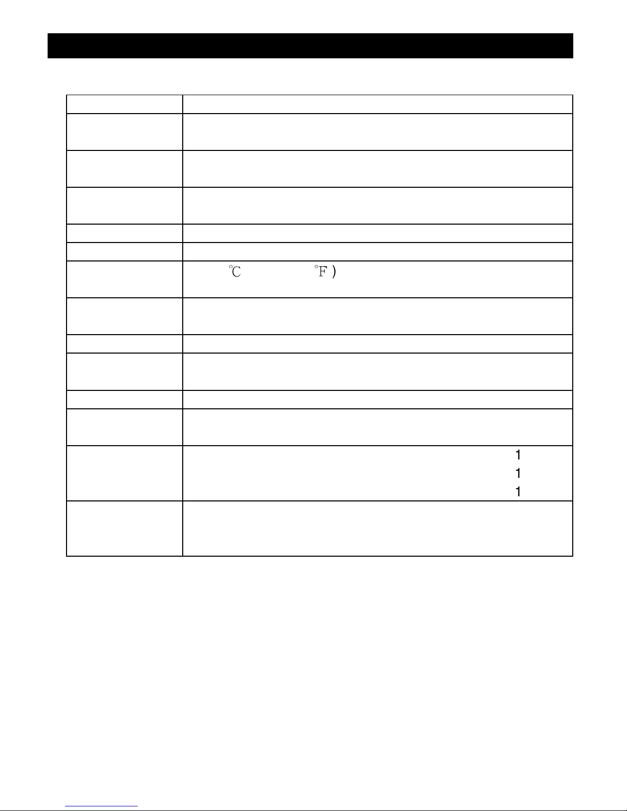
2. SPECIFICATIONS
Circuit Custom single-chip microprocessor LSI circuit
Display LCD Size: 2.36 X 1.75” (60 X 44.4 mm)
Dot Matrix backlit LCD (128 X 64 pixels)
Switch inputs 2 inputs,
Default open
Relay outputs 2 relays
Max. load( 1 ACA/250 ACV , 1 DCA/24 DCV )
Input signal Isolated RS232 signal input
Net mode * Ethernet Mode ( RJ45 )
Operating
0 to 50℃ ( 32 to 122℉ ).
temperature
Operating Less than 80% R.H..
humidity
Power supply AC to DC adapter 9V.
Power DC 120 mA approximately.
consumption Two relays ON approximately DC 200 mA.
Weight 215 g/0.47 LB.
Dimension 134 X 80 X 32 (5.3 X 3.1 X 1.3 inch).
* Dimension is for the meter without terminals only.
Accessories * Instruction manual...........................
...........................................
1PC
included * Hanging unit ( with sticker )......................
..........................
1PC
* AC to DC 9V power adapter.......................
..............................
1PC
Optional * Full line MRC RS232 meters.
Accessories * Data interface cable, UPCB-03.
* Power interface cable, PWCB-06.
2
Page 5
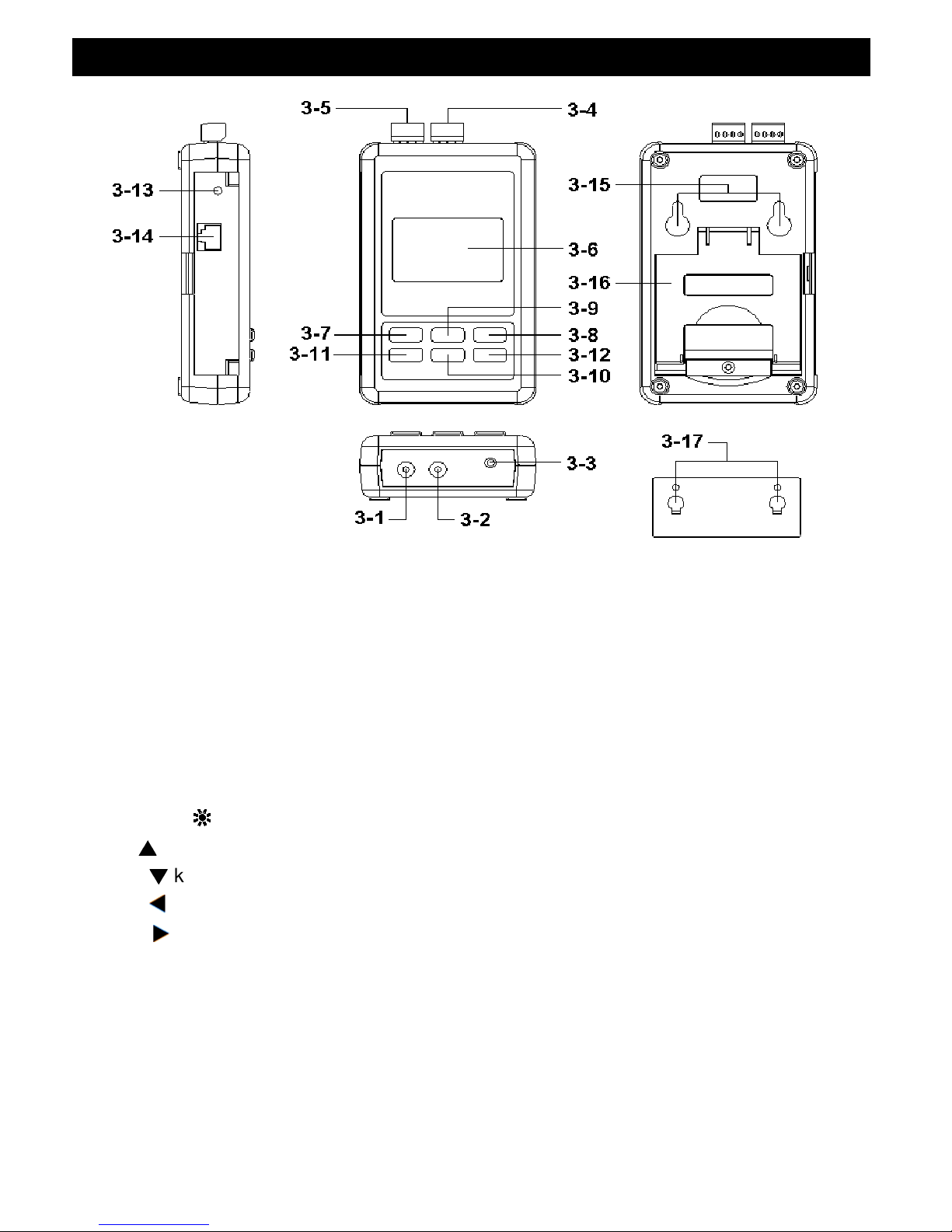
3. FRONT PANEL DESCRIPTION
Fig. 1
3-1 DC 9V Power adapter input socket
3-2 DC 9V output socket
3-3 Isolate input socket
3-4 Input Terminals
3-5 Output Terminals
3-6 Display
3-7 SETUP/ENTER KEY 3-13 System reset button
3-8 EXIT( ) key button 3-14 Network socket (RJ45)
3-9 ▲ key button
3-15 Hanging holes
3-10 ▼ key button
3-16 Hanging unit ( with sticker )
3-11 key button 3-17 Power interface cable/plugs
3-12 key button
3
Page 6
4. MEASURING PROCEDURE
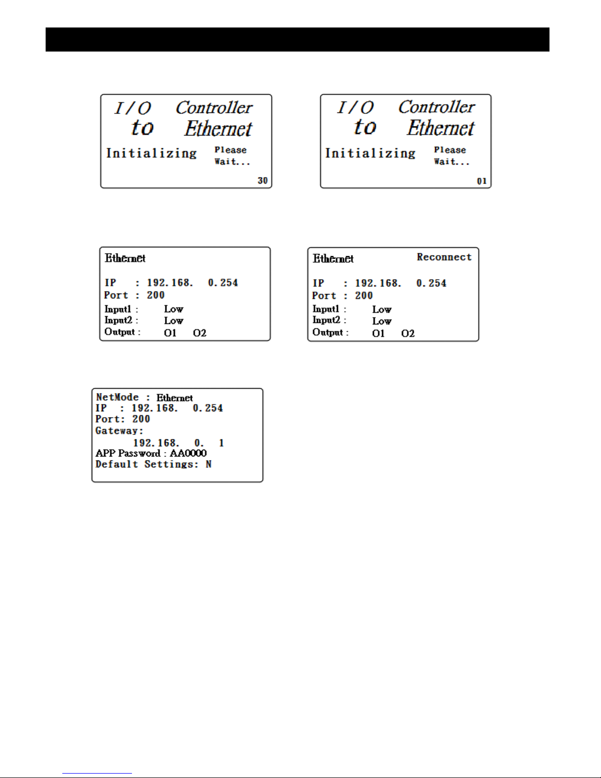
4-1.The initial startup screen
SCREEN4-1-1 SCREEN4-1-2
4-2.
Measuring and setting screens:
1.Measurement screen:
SCREEN4-2-1 SCREEN4-2-2
2.Setting screen:
SCREEN4-2-3
4
Page 7

4-3.
The summary description of keyboard:
1.SETUP(Enter) KEY: Setting screen into the select key.
2.In the setting mode:
2-1.Press
▲
or ▼ to select the field in the upper and lower beating.
2-2.
▲
or ▼ > 2 SEC.: The selected field will rapidly beating.
2-3.
▲
+ ▼ > 2 SEC.: Then the entire column cleanup.
2-4.Press ▲ KEY hold short press ▼ KEY and the right of the text will
be cleared.
2-5. 、 KEY: Left and right keys.
2-6.EXIT/SHIFT( ) KEY: Press key text input type selection or setting
screen left.
3.In the measurement mode:
3-1.In Easy mode, press ▲ + ▼ > 2 SEC. Then turned into full mode.
3-2.In full mode, press ▲ + ▼ > 2 SEC. Then becomes easy mode.
3-3.EXIT/SHIFT( ) KEY: Backlight control key.
4
-4.Setting Description:
1.When the POWER ON, then enter the startup screen countdown 30 SEC.
(SCREEN4-1-1 & SCREEN4-1-2) to 0 SEC. Then enter the
measurement screen (SCREEN4-2-1).
2.Press SETUP KEY once you enter the setup screen as SCREEN4-2-3.
3.In the function directory option Press▲ or ▼ KEY, functional directory
option will flash.
4.Press or KEY into the content selection function directory option
(in this case will flash), After selecting the complete press SETUP KEY
Then back to the function directory option to determine the setting options.
5.Function directory:
5-1.NetMode: Ethernet.
5-1-1. This option is a single option, press ▼ KEY into the IP options
by NetMode.
5-2.IP: The default setting is 192.168.0.254
5-2-1.Press or KEY then enter the option contents, then press ▲ or
▼
KEY to select the number, press the SETUP KEY The contents
do confirm, then will return to the IP directory.
5-2-2.Press
▼
KEY into the Port option from IP.
5-3.Port: The default setting is 200.
5-3-1.Input Range:1-65535.
5
Page 8

5-3-2.Press or KEY then enter the option contents, then press
▲
or ▼ KEY to select the number, press the SETUP KEY The
contents do confirm, then will return to the Port directory.
5-3-3.Press ▼ KEY into the Gateway option from Port.
5-4.Gateway: The default setting is 192.168.0.1
5-4-1.Press or KEY then enter the option contents, then press
▲
or ▼ KEY to select the number, press the SETUP KEY The
contents do confirm, then will return to the Gateway directory.
5-4-2.Press ▼ KEY into the APP Password option from Gateway.
5-5.APP Password: The default setting is AA0000.
4-5.Set value storage:
Press EXIT / SHIFT KEY will set the value of the store, while the return to the
measurement screen, as SCREEN4-2-2. The rewiring after about 25 SEC,
then return to SCREEN4-2-1 screen.
4-6.Ethernet connection:
In SCREEN4.2-1 screen indicates normal Ethernet connection.
4-7.Reply factory setting:
1.Press SETUP KEY once you enter the setup screen as SCREEN4-2-3.
2.Press
▲、▼
KEY select the option to Default Settings item, press
KEY once you enter N option, press ▲ or ▼ KEY select Y press Enter
KEY, will return to directory option then press EXIT / SHIFT KEY will return
to factory default action to do its screen will SCREEN4-2-2, after about
25 SEC later. would return SCREEN4-2-1.
4-8.IO Control Function:
1.First, install MRC dedicated IO APP software:
1-1.The use of smart phones Android or iOS system software download
MRC IO App (SCREEN4-8-1).
1-2.After the download is complete, then install it.
SCREEN4-8-1 SCREEN4-8-2
6
Page 9

2.The machine will boot into the measuring screen (SCREEN4-2-1):
2-1.Set parameters determine the following (SCREEN4-2-3):
2-1-1.IP: 192.168.0.254
2-1-2.Port: 200
2-1-3.Gateway: 192.168.0.1
2-1-2.APP Password: AA0000
2-2.Start smart phone, open the IO App software, for native control.
2-3.IO App software-related settings section:
2-3-1.At this show SCREEN 4-8-3, select Step2 tool button then
into the SCREEN4-8-4.
2-3-3.Enter the relevant information in SCREEN4-8-4:
1) IO name: The user can change the name of the desired.
2) IP:
A. Internal network: IP of the machine to do based on inputs (can
also be entered into SCREEN4-8-6 way) and shall check.
B. External network: IP based network used by the user to make
an input (can enter into SCREEN4-8-4 or SCREEN4-8-5
By the way) and shall check.
3) Port: This machine is made in accordance with port input.
4) Password: According to the machine APP Password as input to
control after a successful check.
5) Relay1 Time: Enter the control time Relay1 ON, the choice in
seconds or minutes.
6) Relay2 Time: Enter the control time Relay2 ON, the choice in
seconds or minutes.
2-3-4. In SCREEN4-8-4 Screen Save tool button, then press Save the set
value is stored,and it will return to SCREEN4-8-3 screen when
Step2 wired green and flashing it means that this machine is wired.
2-3-5. Reconnect (SCREEN4-8-3 of STEP3): When they find breaking
news is not connected to WiFi, you can press this do to reconnect
action.
2-4.IOApp Software Operating Instructions:
2-4-1.IO1~IO4 selection: SCREEN4-8-3 as the STEP4.
2-4-2.RELAY CONTROL:
1) MANUAL RELAY1 OR RELAY2 ON/OFF CONTROL:
When RELAY1 or RELAY2 OFF (SCREEN4-8-3 of STEP 6),
press the ON / OFF BUTTON (SCREEN4-8-3 the STEP5).
7
Page 10

long press> 2 SEC. By OFF to ON (eg SCREEN4-8-6 ), while the
unit's OUTPUT DISPLAY Its O1 or O2 will be blinking
(eg SCREEN4-8-10).
2) TIME RELAY1 OR RELAY2 ON/OFF CONTROL:
When RELAY 1 or RELAY 2 is OFF (SCREEN4-8-3 of
STEP6), CONTROL MODE to MANUAL state (SCREEN4-8-3 of
STEP7). In this case, press CONTROL MODE BUTTON Long press
> 3 SEC. Then becomes tIME state and RELAY1 or RELAY2 ON
time, will be based on RELAY1 or RELAY2 TIME set time to control.
* EXT:
A.The RELAY1 or RELAY2 Time Set 5 SEC. (SCREEN4-8-4).
B. Press RELAY 1 or RELAY CONTROL MODE BUTTON>
3 SEC.(SCREEN 4-8-3 of STEP7).
C. Press RELAY1 or RELAY2 ON / OFF BUTTON> 2 SEC.
(SCREEN4-8-3 of STEP5) is RELAY1 or RELAY2 becomes
ON, and the machine of its OUTPUT O1 or O2 will be blinking
(eg SCREEN4-8-10), 5 SEC. after RELAY1 or RELAY2
automatically turns OFF, and OUTPUT of this unit bec
omes
their O1 orO2 stationary state.
2-4-3.INPUT STATUS:
1) INPUT1 OR INPUT2 DETECT ON(SCREEN4-8-3 of STEP8):
When the unit of INPUT1 or INPUT 2 terminal first short circuit,
the machine will be made of INPUT1 or INPUT2 LOW becomes
HIGH (eg SCREEN4-8-11 and SCREEN4-8-12),while IO APP
INPUT1 or INPUT2 symbol lights up (such as SCREEN4-8-7).
2) INPUT1 OR INPUT2 PULSE LOW:
According to the NO.1, when INPUT1 or INPUT2 Terminal of
this machine becomes open again by a short circuit, the machine
will display the INPUT1 or INPUT2 LOW PULSE (eg SCREEN
4-8-13), and IO APP INPUT1 or INPUT2 symbol darken
And PULSE symbol lights up (such as SCREEN4-8-8).
3) INPUT1 OR INPUT2 PULSE HIGH:
According to the NO.2, when the native of INPUT1 or INPUT2
terminal becomes open again by the short circuit, the machine will
display the INPUT1 or INPUT2 HIGH PULSE
(eg SCREEN4-8-14), and IO APP INPUT1 or INPUT2 and
PULSE symbol lights up(such as SCREEN4-8-9).
8
Page 11

4) INPUT1 OR INPUT2 PULSE CLEAR:
According SCREEN 4-8-8, press PULSE CLEAR BUTTON
(eg SCREEN4-8-3 the STEP10), The screen becomes
SCREEN4-8-10 state, and this machine screen INPUT1 or
INPUT2 becomes SCREEN4-8-11.
SCREEN4-8-3 SCREEN4-8-4 SCREEN4-8-5
SCREEN4-8-6 SCREEN4-8-7 SCREEN4-8-8
9
Page 12

SCREEN4-8-9 SCREEN4-8-10 SCREEN4-8-11
SCREEN4-8-12 SCREEN4-8-13 SCREEN4-8-13
4-9.RS232 transmission function:
1.First, install MRC dedicated APP software:
1-1.The use of smart phone Andriod or iOS system software download MRC
MeterApp (SCREEN4-8-1), Andriod Password: Az6210 ,iOS Password:
aZ6210.
1-2.After the download is complete, then install it.
SCREEN4-9-1
10
Page 13

2.When using MRC meter can be RS232 output, insert IOW-924E RS232 INPUT
(Fig.3-3), this time the machine will automatically become RS232 transmission
function by the IO control function.
3.Open Meter App software (such as SCREEN4-9-22):
3-3-1. In SCREEN 4-9-2 select Step 1 (Meter 1).
3-3-2.At this show SCREEN4-9-3, select Step2 tool button then into the
SCREEN4-9-4.
3-3-3.Enter the relevant information in SCREEN4-9-4:
1) Meter name: Meter name can be changed to a desired user name
2) CH NO.:In accordance Meter CH NO. Input
3) Sampling time: In minutes, checking after do Logger function (must be set)
4) IP:
A. According to the local IP as input (such as SCREEN4-9-4) and shall
be checked.
B. IP based network used by the user to make an input
(such as SCREEN4-9-5) and must check.
5) Port: According to the machine port as input and must check (must be set).
6) Save file: Logger select the path you want to store (must be set)
7) Alarm Beeper: After checking SCREEN4-9-7 must comply with the set,
when they meet the conditions have an effect.
8) Alarm SMS: Check this option must be compatible with
SCREEN4-9-7 set,when qualified will send newsletters.
3-3-4.In SCREEN4-9-5 Save tool button, then press Save the set value is
stored, and it will return to SCREEN4-9-3 screen, when Step3 green
and flashes when it means that the connection with the machine.
3-3-5.In SCREEN4-9-3 Step 4 (CH1) Click proceeds SCREEN4-9-6
screen, then do High and Low set and checked, when you press the
Return of smart phones will be returned to SCREEN4-9-3 screen
equivalent measured value has reached the condition CH1-CH3 will
show red numbers and have Beeper and send newsletters.
3-3-6.In SCREEN4-9-3 Step5 tool button, you can switch directly displays
the value of Meter1-Meter4.
3-3-7.Re-connect: When they find breaking news is not connected to WiFi,
you can press this do to reconnect action.
3-3-8.Auto Log: Sampling time basis function set the ti
me and check,
do the automatic recording function (such as SCREEN4-9-4).
11
Page 14

3-3-9.Manaul Log: Each time you press the tool button, then record sum.
* Record file format is xml.
3-3-10.View Log: The recorded data can be seen directly in the smart phone
(eg SCREEN4-9-7).
4.When IOW-924E RS232 INPUT No signal detected, approximately 20 seconds
will automatically cut the IO control functions.
SCREEN4-9-3 SCREEN4-9-4
SCREEN4-9-5
SCREEN4-9-6 SCREEN4-9-7 SCREEN4-9-8
12
Page 15

4-10.Direct connection network mode (internal network):
1.Network schematic diagram:
2.Related parameters:
2-1.IP: 192.168.0.254
2-2.Port: 200
2-3.Gateway: 192.168.0.1
2-4.APP Password: AA0000
3.IO APP setting mode: As shown SCREEN4-8-6.
4-11.Direct connection network mode (external network):
1.Network schematic diagram:
2.Related parameters:
2-1.IP: 192.168.0.254
2-2.Port: 200
2-3.Gateway: 192.168.0.1
2-4.APP Password: AA0000
3.IO APP setting mode: As shown SCREEN4-8-4 or SCREEN4-8-5.
4-12. the unit via a wireless bridge network connection
(external network fixed IP):
1.Network schematic diagram:
2.Related parameters:
2-1.IP: 192.168.0.254
2-2.Port: 200
2-3.Gateway: 192.168.0.1
2-4.APP Password: AA0000
13
ModemInternet IP Router LAN PORT IOW-924E
ModemInternet IP Router LAN PORT IOW-924E
Internet Modem IP Router Wireless(AP) Wireless(Bridge) IOW-924E
Page 16

3.into the IP Router do parameter setting, set the contents of the red box.
4-13.the unit via a wireless bridge network connection
(external network floating IP):
1.Network schematic diagram:
2.Related parameters:
2-1.IP: 192.168.0.254
2-2.Port: 200
2-3.Gateway: 192.168.0.1
2-4.APP Password: AA0000
14
Internet
URL forwarding
server
Modem IP Router Wireless(AP)
Wireless(Bridge) IOW-924E
Page 17

3.into the IP Router do parameter setting, set the contents of the red box .
4.Go www.dlinkddns.com site for a free transfer, will be transferred to the name
of the applied input address to the IP Router.
15
Page 18

5.When performing IO APP or Meter App,Enter the desired parameters shall
utilize IP Tools software to enter after that.As SCREEN4-8-4,
SCREEN4-8-5 or SCREEN4-9-4.
16
 Loading...