

Page 1
1
Mobile-type PTC Steam Humidifier for office or commercial space
HU-24
INSTALLATION AND OPERATION MANUAL
PLEASE READ THIS MANUAL CAREFULLY BEFORE OPERATION
3, Hagavish st. Israel 58817 Tel: 972 3 5595252, Fax: 972 3 5594529 mrc@mrclab.com
MRC.12.16
Page 2
2
Safety Caution
Be sure to read before use. Keep this manual handy for the users to consult at
any time necessary.
The cautions shown here are to ensure the safety in use of the humidifier and to
preclude any danger and damage to the users and others. What could
conceivably result from wrong handling is identified in the form of either
“Warning" or “Caution". They should both be observed strictly as important
points that pertain to safety.
WARNING
CAUTION
Matter that could cause death or
serious injury to human
Matter that could cause injury to
human or damage to property
WARNING
●Do not insert and remove AC plug with wet hands, it may cause electrical shock.
● The nominal current of AC plug having more than 5A must be used singly, not
combination use.
● Do not touch any electric circuit during power on especially by wet hands. It will get electric
shock.
● All of electric cable/wire should not be damaged, processed, pulled or forcibly bended. It will
cause electric leakage and make fire or electric shock.
● All of electric cables/wires should not bind or tie not to cause electric leakage or firing.
● When you have noted smoking or abnormal smell, shut off electric power source
immediately and also off the power switch of the unit. If you keep running the unit it may
cause fire or electric shock. Then please report it to the supplier immediately.
● Do not disassemble the unit except cleaning purpose and also do not modify the unit. It
may cause fire or electric shock.
●Do not splash any water on the unit. It may cause short circuit or electric shock.
Page 3

3
CAUTION
●Be sure not put hands, face close to the steam outlet port, it may cause getting burned.
●Do not move or shake the unit during the operation. It may cause electric shock or
leakage.
●Do not install or locate the unit where such as unstable or vibrating places. The units
may fall down and hurt the people around there.
●Do not install or locate the unit where dusty place , sun shine light exposing directly,
high temperature, close to fire. All are very risky for the fire of the unit.
●Keep open through around the electric plug to shut down the power easily at any
emergency cases.
●Use only specified electric power source and no other voltage required.
●Connect Ground without fail otherwise earth leakage breaker will not work.
●Before carrying out the cleaning works, cut off the power source, otherwise it may cause
electric shock.
●Before carrying out the cleaning works, cut off the power source, and wait till the
temperature get down in the water reservoir, otherwise, it may cause getting burned.
●Do not use extension cables, it may cause electric shock or fire.
●Drain off all water from the water tank and water reservoir if you stop the running for a
while. Otherwise, it cause the offensive odor created by some bacteria and it may affect
health.
●Use only clean water (R.O or Pure water) for the unit. Other liquid may cause trouble of
the unit and make fire or electric shock.
Page 4
4
2
0
0
0
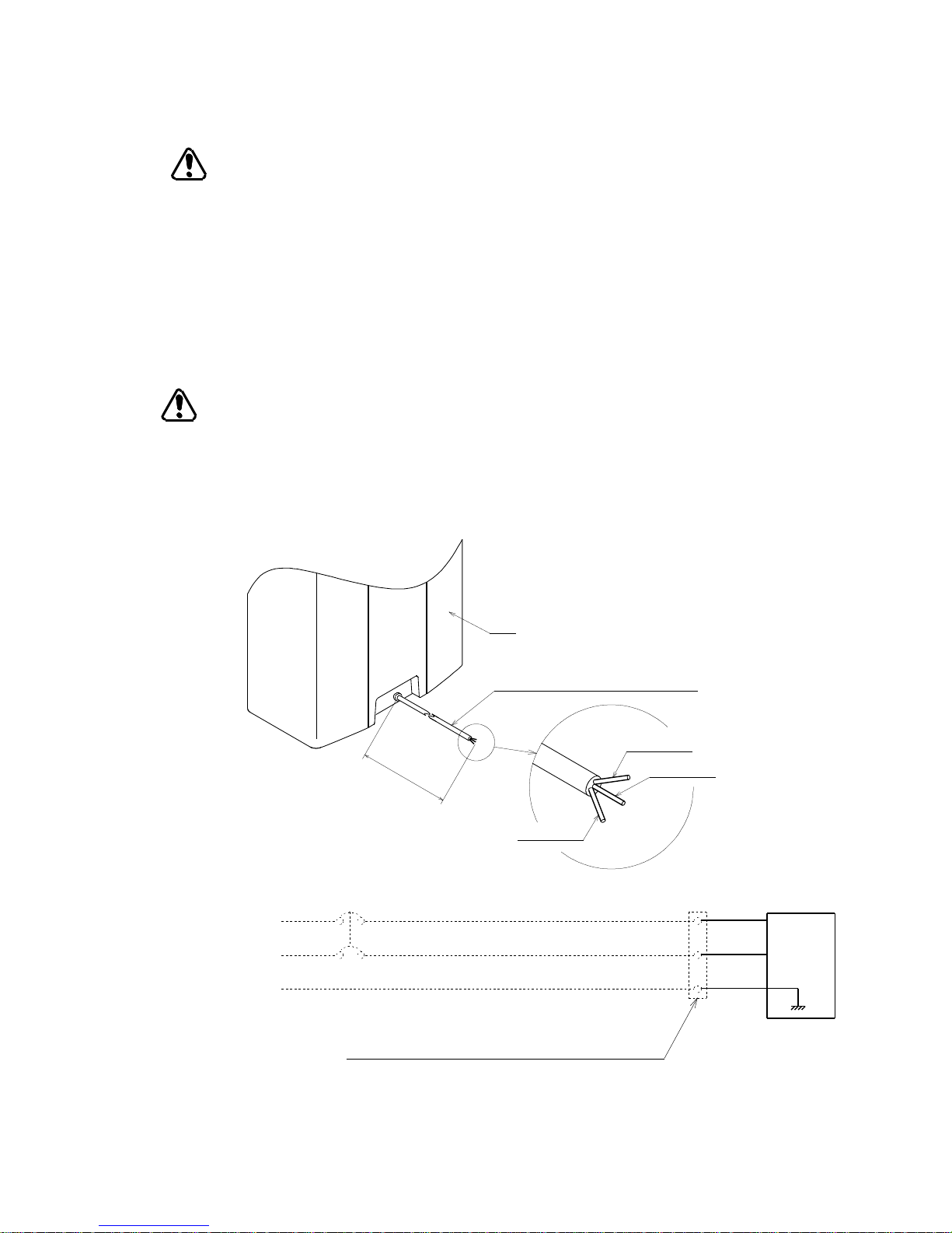
White line
Black line
Green line
Back
Power cable(VCTF-22 3core×2SQ)
CAUTION for Installation Location
1. Do not install or locate the unit where such as unstable or vibrating places and the unit
should be horizontally-supported.
2. Put the unit away to keep certain distance from surrounding area.
3.Steam comes out from the steam outlet port, it may invite errors in control mechanisms
installed near by the unit, and also may change the color of the furniture or wall.
4. Do not install or locate the unit where dusty place, sun shine light exposing directly,
high temperature, close to fire. All are very risky for the fire of the unit.
CAUTION for Electrical Work
1. Use only dedicated line for the humidifier to supply power and install ground fault
interrupter. (switch panel )
Power supply : AC230V, Rated power : 2.1kW.
2. Power source should be connected to white and black line of power cable and green line
should be connected to earth.
Electrical working drawing
Dotted line parts should be arranged by customer.
Electrical leakage breaker(AC230V-20A induced current 30mA)
AC230V 50/60Hz
Earth
White
Black
Green
unit
Humidifier
Earth
Intermediary terminal or high capacity socket
Page 5
5
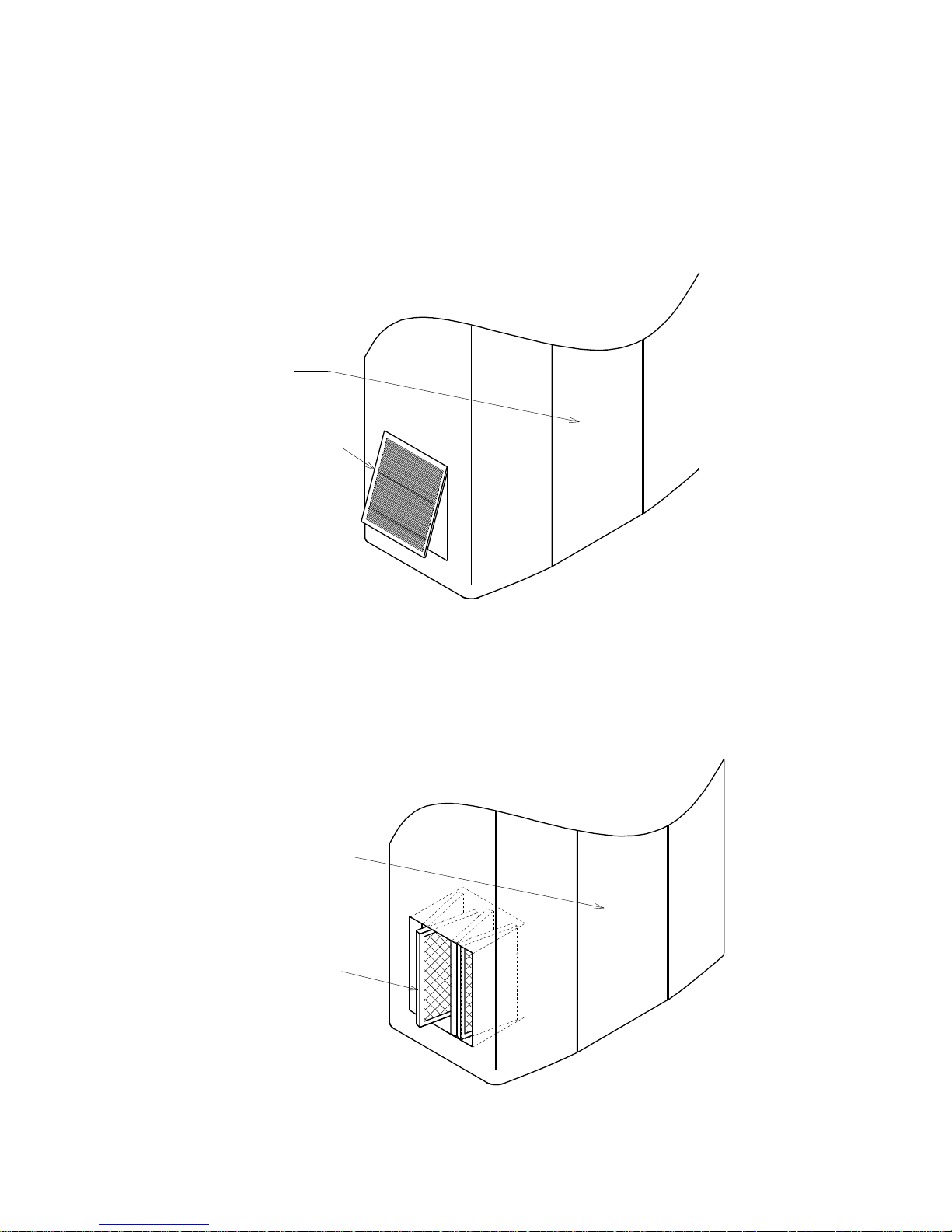
Front
Air inlet port
Front
Titanium dioxide filter
Note on operation
Various kinds of the filters
1. Pre-Filter
The filters are installed at the back side of each air inlet ports on both sides of the unit to
protect the suction of dust. (Please refer to P14 for cleaning.)
2. Titanium dioxide filter
3 sheets of the titanium dioxide filter are installed inside the air inlet port on the left side
of the unit to give hygienical, odorless air and sterilize the bacteria and the virus. (Please
refer to P15 for cleaning.)
Page 6
6
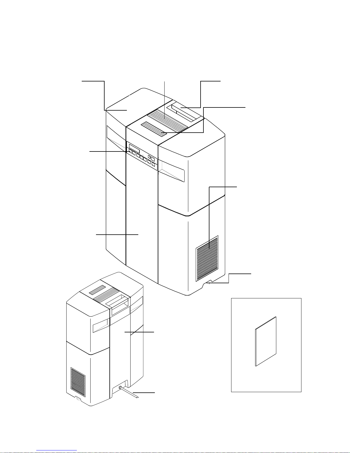
1. Product overview
Front view
Water tank cover (on either side) Steam outlet port Handle
Clean air outlet port
Operation
buttons
Air inlet port
(on either side)
Front panel
Back view Adjuster
Accessory
Back side panel
Installation and
operation manual
Power cable
On the right side: built in humidity sensor
On the left side: built in air cleaning unit
Page 7
7
8
6
4
2
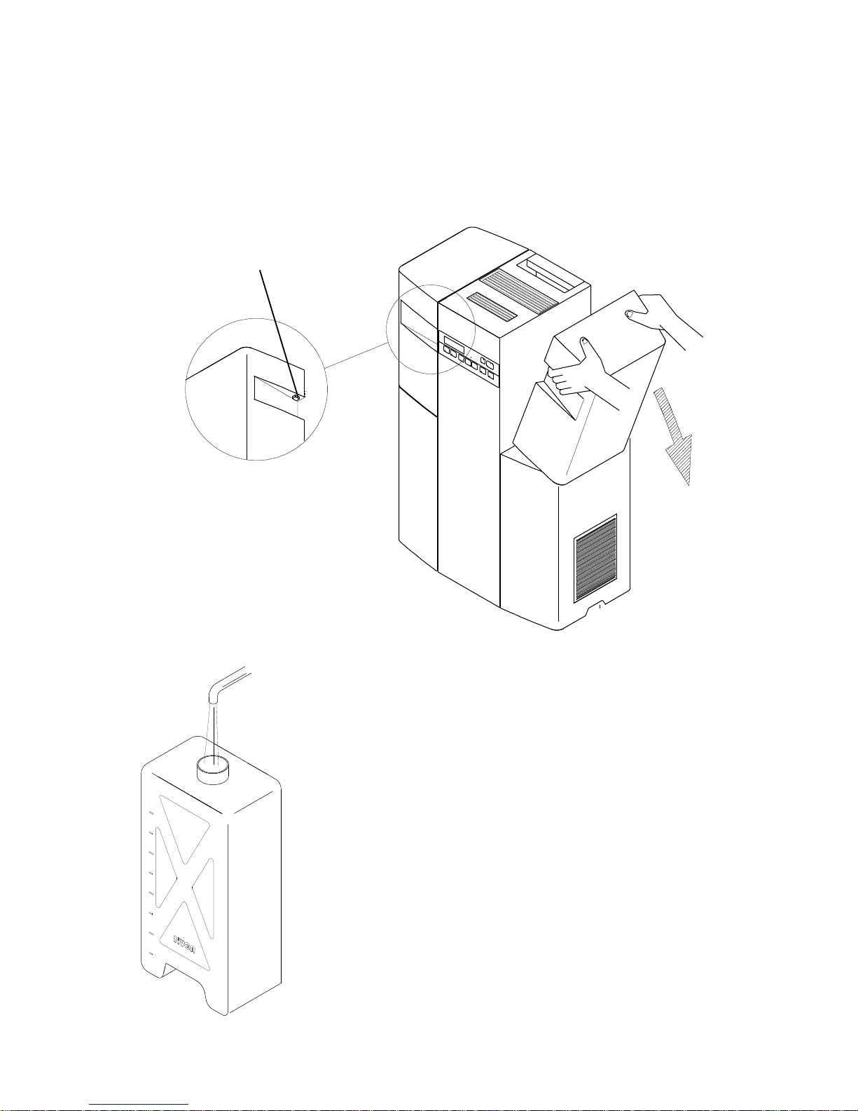
2. How to remove the water tank cover
Push the unlock button situated on upper parts of both front and rear sides at the
hollow parts of the cover and remove it to the arrowed line showing in the below.
Unlock button
3. Supplying water
Pure or R.O water should be used.
1. Open the water tank cover, and pull out the water tank.
2. Remove the cap for the water tank, and fill up the pure or
R.O water in the tank.
3. Fasten the cap tightly and set back the water tank to the unit
and close the tank cover.
Page 8
8
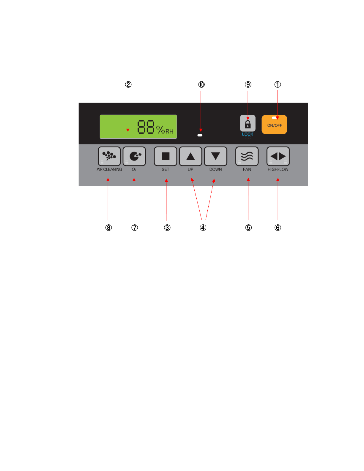
4. Function of the display and operating elements
①. ON/OFF key (Power Switch) : Switch the unit On or Off.
②. Operating display : Shows current humidity and functions.
③. Set switch for setting humidity level : Set humidity level with switch ④
④. Setting humidity level : Set the humidity level up and down with pushing SET
switch ③ at same time.
⑤. Ventilation switch : Switch the ventilation On and Off .
⑥. Heater output : Change for high power (2kW) or low power (1kW) with pushing
SET switch ③.
⑦. Sterilization switch : Switch the sterilization function On or Off .
⑧. Air cleaning switch : Switch the air cleaning function On or Off.
⑨. Lock switch : Child lock for all function by pressing the button for 3 seconds.
⑩. LED for water supply : When the water tank gets empty, LED lights with alarm.
Page 9
9
5. Operation
Notes on operation :
1. Fill the pure or R.O water in the water tank.
Open the tank cover and remove the water tank then fill the pure or R.O water into
tank, and set back it to the unit to according to P.6.
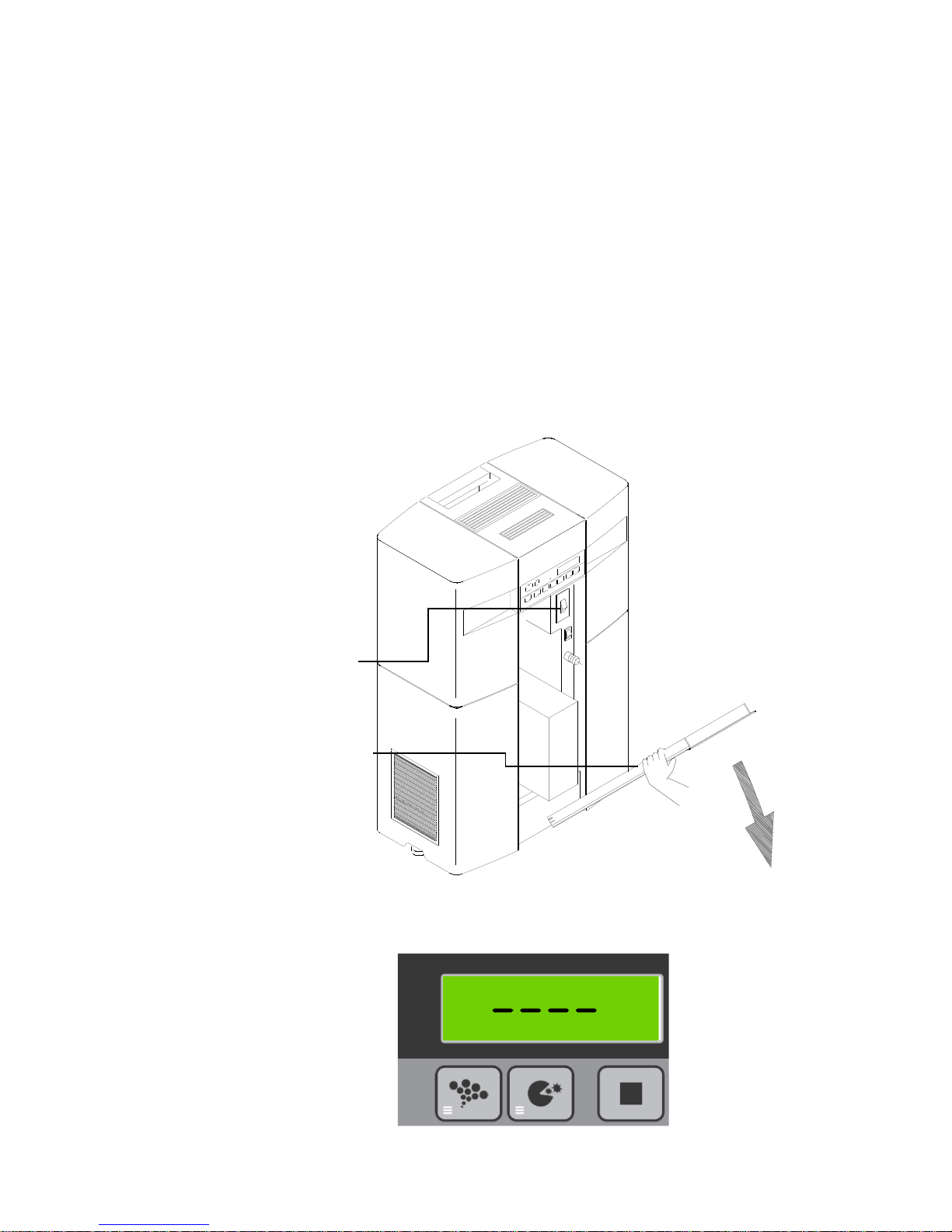
2. Power Supply
2-1 After finishing electric work according to P.3, open the tank cover and pull the back
side panel to the direction of arrow as shown below.
2-2 Push the electrical leakage breaker ‘’On’’.
Close the back side panel.
2-3 Switch on the power switch on the display panel.
Electrical
leakage
breaker
Back side panel
2-4. An alarm will sound when the power is supplied, then the display shows the
standby operation status as shown below.
Page 10
10
Operating the control unit.
1. Press the On/Off key.
An alarm will sound and show the current humidity on the display panel.
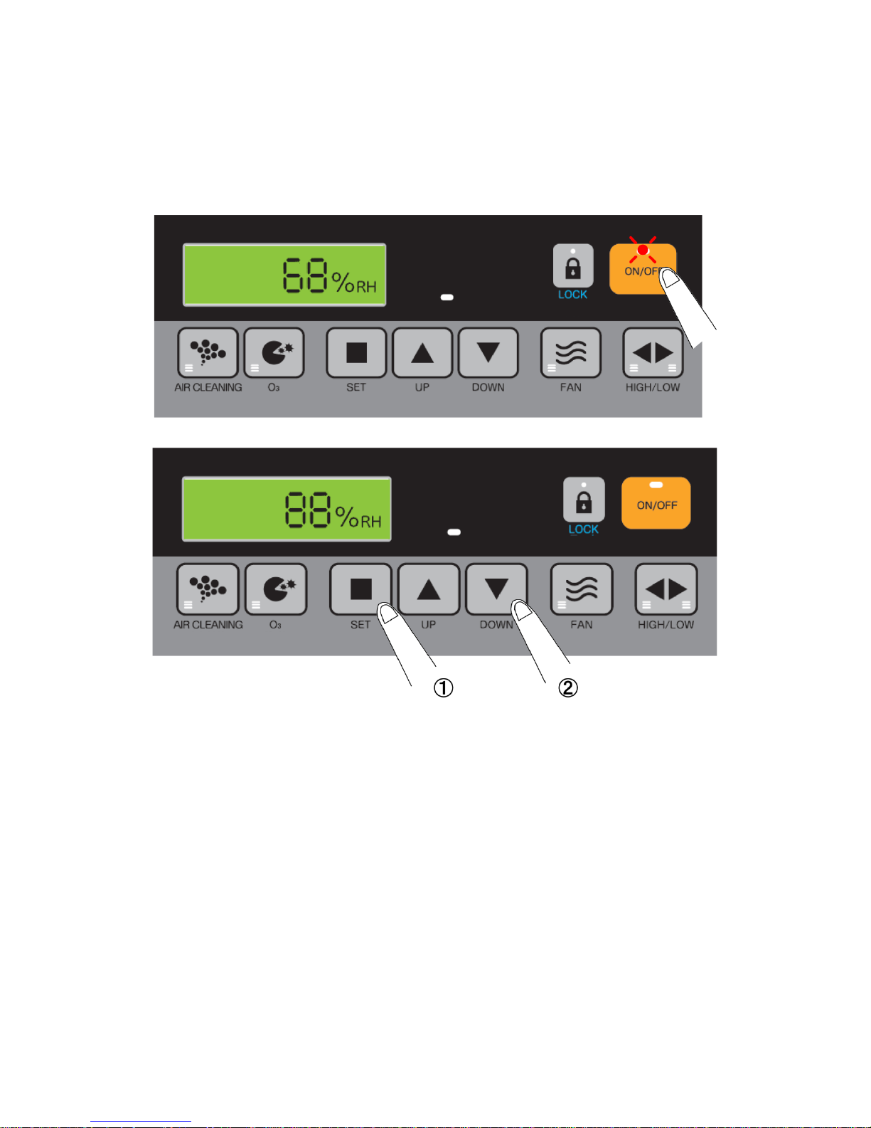
2. Set the required humidity level in %.
- Push the SET switch on the panel, it shows the humidity level setting by last time.
- If you require other humidity level, push UP or DOWN switch with pushing SET
switch.
Factory setting: 50%
Setting range : 0-99%
- If you disengage a finger from SET switch, then the display shows current humidity.
3. Start of steam generation
When the current humidity is lower than the setting humidity, the unit is activated and
starts generating the steam after about 10 minutes.
4. Shutdown the unit
By pushing the’’ On/Off ‘’switch, an alarm will sound and indicate ‘’-----‘’ in the display
then the unit will shutdown in about 10 minutes after run of the ventilation.
Page 11

11
Other functions
1. Ventilation switch
By the ventilation switch, it can spread the steam from the outlet port.
Please set the switch ‘’On’’ under the normal operation.
Note : Be sure not to put hands, face close to the steam outlet port, it may cause
getting burned. If you operate the unit with ventilation switch ‘’OFF’’ the hot
steam comes out from steam outlet.
2. HIGH / LOW switch for heating power.
Switch to change the humidifying heater to high or low.
Can change the humidifying heater high or low by pushing this switch with pushing
SET switch at the same time. LED display shows high in the left and low in the right
sides.
High setting Low setting
Page 12

12
3. Air Cleaning switch
To clean air.
Clean air will be supplied in the room from air sanitization outlet port.
4. Switch for sterilization
To sterilize air.
Sterilized ozone is emitted inside the room from the air sanitization outlet port.
5. Switch for Rock
Child lock for all function by pressing the button for 3 seconds.
The lock is released by pressing another 3 seconds.
Page 13

13
Fault indication
1. Warning for water supply.
1-1 When the water tank gets empty, ‘’FEED WATER’’ is shown in the display with
alarm and stop the unit automatically.
1-2 Fill water in the tank, and set back to the unit, then Error LED in the display and
alarm are disappeared then the unit restarts.
Note : Warning alarm can be switched off by pushing lock switch.
2. Exchange the UV lamp for air cleaning.
2-1 When UV lamps built in the air cleaning unit has exceeded the life time and no
lighting up the UV lamp, LED lights and showing the error message in the
display with alarm.
2-2 Replace the UV lamps, error message is disappeared after replace the UV
lamps, and restart the air cleaning operation. ( please refer P16 for
replacement of UV lamp )
* Warning alarm can be switch off by pushing the lock switch.
Page 14

14
6. Cleaning the unit
CAUTION
Drain off all water from the water tank and water
reservoir if you stop the running for a while.
It cause the offensive odor created by some bacteria and it may affect
health.
Before carrying out the cleaning works, cut off
the power source.
It may cause electric shock.
Before carrying out the cleaning works, cut off
the power source, and wait till the temperature
get down in the water reservoir.
It may cause burn injury.
WARNING
Do not splash any water on the unit.
It may cause short circuit or electric shock.
Do not maintain the unit while in use or shortly
after operating.
It may cause burn injury.
Page 15

15
2
4
6
8
1 Cleaning the water tank.
When the inside of the tank gets dirty, put some water in the tank and close the cap
firmly, and wash by shaking.
2 Cleaning the pre-filter
2-1 Pull out the handle under the air inlet ports as shown below sketch and take out air
inlet ports.
Air inlet port
2-2 The pre-filter is inserted at the back side of the air inlet port.
Pull out the pre-heater, and take up dust by vacuum.
Page 16

16
Air inlet port
Pre-filter
Page 17

17
Front
Titanium dioxide filter
3 Cleaning the Oxidized Titanium Filter
3-1 3 sheets of oxidized titanium filters are installed inside the air inlet port at the left
side of the unit. Take out the air inlet port and pull out the filters.
3-2 Wash oxidized titanium filters lightly in water and dry in the sun, then back them to
the unit.
Note: There is no opposite sides to the same oxidized titanium filter.
①Wash in the water.
②Dry in the sun.
Page 18

18
Front
Titanium dioxide filter
4 Replace UV lamp
4-1 3 sheets of oxidized titanium filters are installed inside the air inlet port at the left
side of the unit. Take out the air inlet port and pull out the filters.
4-2 UV lamps are plugged in the sockets, so pull out the lamps as shown the below, and
replace them with new lamps.
Note : There is no polarization setting for the UV lamps.
Be sure to plug the lamps firmly into the sockets.
4-3 After replace the UV lamps, set the oxidized titanium filters on the position and fix
the air inlet port.
Note : There is no opposite sides to the same oxidized titanium filter.
UV lamp
Socket
Page 19

19
5 Replacing the lamp for sterilization
5-1 Open the water tank cover on the left side of the unit, and pull out the tank as
shown the below.
5-2 Loosen 2 screws on the side cover, and remove the side cover as shown the below
sketch.
Side cover
Page 20

20
5-3 Pull out lamp unit for sterilization from ventilation duct inside the unit, and
disconnect the lead from connector.
Connector
Ventilation duct
Lamp unit
5-4 Replace the lamp unit for sterilization with new one as set.
5-5 Installation of the unit follows the reverse sequence.
Page 21

21
6 Drainage water from the unit
CAUTION
Drain off all water from the water tank and water reservoir if
you stop the running for a while.
It cause the offensive odor created by some bacteria and it may affect health.
Before carrying out the cleaning works, cut off the power
source.
It may cause electric shock.
Before carrying out the cleaning works, cut off the power
source, and wait till the temperature get down in the water
reservoir.
It may cause burn injury.
6-1 Open the tank cover, then open the front panel to the direction A as showing the
below sketch. .
Remove the panel by pulling out to the direction B as showing below sketch.
A
B
Page 22

22
6-2 Remove 2 water tanks.
6-3 Supply the main power to the unit, and setting Stand-by operation.
Display showing when stand-by operation.
Part Names
Drainage switch
Drain port
Drain hose
Bucket (arranged by customer)
Page 23

23
6-4 The drain hose plugged into the drain port is jointed with bucket.
Drain hose
Bucket
(arranged by customer)
6-5 Drain starts when setting ‘’On’’ the drainage switch.
When the water is completely drained, setting‘’ Off’’ the drainage switch.
ELB
Drainage switch
6-6 Setting ‘’Off’’ the power supply switch after drainage.
6-7 Put back the front panel to the original position.
Page 24

24
7 Cleaning the water reservoir
Water reservoir must be maintained on a periodic basis and in the off-season by
following procedure.
7-1 Finishing drainage of the water in the unit. Clean the water reservoir.
7-2 Remove the back panel of the unit
Water reservoir
7-3 After confirming switching off the switch panel and earth leakage breaker on the unit,
remove the heating cables from terminal block.
Heating cable
黒
赤
白
Page 25

25
7-4 Unfasten the hose band and pull out the steam hose from the top cover of the water
reservoir.
Steam hose
Hose band
7-5 Unfasten 2 screws fixing the water reservoir.
Fixed bracket
Fixing screw
Top cover of the
water reservoir
Page 26

26
Plastic brush
7-6 Push up on the water reservoir as shown the below and remove water reservoir from
the unit.
Water reservoir
Water supply tube
Note: There is some water left in the water reservoir, so tilt the reservoir direction to the water
supply hose when detaching the reservoir from the unit.
7-7 Remove the top cover of the reservoir, and remove any limescale by a brush ( do not use
a wire brush ) inside the water reservoir and top cover, then wash them up with clean
water.
Page 27

27
7-8 After cleaning the water reservoir, water supply tube fixed in the bottom of the water
reservoir must be screwed firmly with water supply port of the unit.
Water supply tube
Water supply port
Note: O- ring is installed in the water supply tube.
Degradation and deformation of O-ring cause the leakage of the water, so
need to check O-ring when mounting the water reservoir, and replace with
new O-ring if needed.
O-ring
7-9 Installation of the water reservoir follows the reverse sequence.
Note: In order to avoid mishandling the unit, please set ‘’Off’’ for both switch panel
and earth leakage breaker.
Page 28

28
s
o
u
n
d
B
o
i
l
i
n
g
B
u
b
b
l
i
n
g
B
u
b
b
l
i
n
g
7. Daily Maintenance
1 Cleaning each filter
- When the filters get dirty at air inlet port.
- Periodic basis.
Pre- filter at air inlet port : every 3~4 months
Oxidized Titanium Filters (3 sheets) : every 3~4 months
2 Drainage the water reservoir
Produce the sounds of water boiling coming from the unit during on operation is the
sign that the water in the reservoir get dirty.
Please drain water from reservoir or cleaning the reservoir.
3 Wiping the body of the unit.
The places like steam output port and air inlet ports get dirty easily, so wiping by wet
clothes when they get dirty.
To use HU-24 long term.
We recommend the customer to drain the
water from the reserv oir regularly.
In case of ON-SE ASON, it is desirable to
drain the water once per week.
Page 29

29
8. Trouble Shooting
Trouble function
Possible reason
countermeasure
No operation
No electric power switch on
Supply the power
Switch off earth leakage
breaker
Switch on earth leakage
breaker
Not setting humidity level
Setting humidity level
LED lights for water supply
Supply water
LED lights for water supply
Empty in the water tank
Supply water
Censor for supply water getting
dirty *
Cleaning the censor
No steam output
Soon after the switch on the
unit
Need about 10 minutes to
get steam
Wrong setting of humidity level
or lower setting humidity than
current humidity
To check the setting humidity
level
LED lights for water supply
Supply water
Less output the steam
Mossy surface in the water
reservoir ?
Clean the water reservoir
Empty in the water tank
Supply water in the tank
Dirty at the steam outlet port
Clean the steam outlet port
Have an abnormal noise
Mossy surface in the water
reservoir ?
Clean the water reservoir
Have an unusual odor
Not carried out the drainage in
the water reservoir
Drain the water in the water
reservoir
Triggered by short circuit or
electric leakage
Do service call
Not control the switch
Rocked the rock switch
Release the rock switch
Plastic brush
Water supply sensor
*Position of the water supply censor
The water supply sensor is installed in the water
tank receiver at right side of the unit.
Clean the sensor that looks dirty using nylon brush.
Page 30

30
9. Maintenance list
To maintain operational safety, MRC must be maintained at regular
intervals.
Below you will find a summary of the work to be carried out for each of
maintenance stages take into consideration of annual number of operating hour
as 1,000 hours.
Components
Work to be done
( 1time / year )
Approx. time for
replacement (years)
Pre-filter
Cleaning of dirt
3
Oxidized titanium filter
Wash lightly in water
5
UV lamp for air cleaning
Wipe the lamp with a dry
cloth
10
Lamp set for sterilization
Wipe the lamp set with a
dry cloth
10
Drain pump
----
3
PTC immersion heater
Cleaning of dirt
3
Each hose/pipe
Cleaning of the dirt inside
the hose/pipe
3
Steam hose
-----
5
10. Warranty
Please see P.33 of this manual for the detail.
Page 31

31
11Specification
Power supply
AC230 V 50/60Hz
Rated power
(L)1100w / (H) 2100w
Steam output
(L)1.2kg/h / (H)2.4kg/h
Air volume at steam outlet port(Max)
30 m3/h
Air volume for air cleaning, and
sterilization (Max)
30m3/h
Water tank capacity
10 L x 2
Humidity display range
10_ _ _99%RH
Water quality
Pure or R.O water
Auxiliary function
Output switch ( L ) & (H )
Display for current relative humidity
( %RH)
Function for air cleaning
Function for air sterilization
Fault indications on display
Ambient condition
0…40˚C(No freezing), Max.70%RH
Weight
Dry: 24.5kg Full: 44.5kg
External dimensions(mm)
Page 32

32
Wiring diagram
Page 33

33
WARRANTY
MRC warrants to the original first customer that the products will be free from defects
in material and workmanship for only the period of 12 months from the date of
delivery from the MRC factory.
If any MRC product is proven to be defective in the material or workmanship by MRC
during above applicable warranty period, MRC only will repair or supply replacement
for the defective product at free of charge. And only after having informed by MRC, the
customer can return the defective parts to MRC without any charge, the costs for
transport of the parts to be repaired shall be borne by MRC.
In case of replaced or repaired the goods, the original warranty period shall be
kept. MRC shall not be liable for under any circumstance:
1. If all actions described in MRC’s installation and operation manuals do not carry
out even by well trained and sufficiently qualified personnel authorized by the owner.
2. If the customer do not follow MRC’s installation and operation manuals.
3. If the products have been modified, or altered without written agreement with
MRC.
4. Under circumstances of any direct, indirect, incidental, consequential damages, or
damages for injury occurrence to person or property, loss of business or information,
loss of profit or production interruption in relation to the manufacture or use of the
products.
5. Any damage or malfunction due to act of providence such as earthquakes or fires.
6. Any damage or malfunction during transportation or transfer such as dropping the
product after the purchase.
7. Any damage or malfunction caused by other source not directly caused by MRC
products.
8. Any damages or malfunctions caused by mishandling or unauthorized repairing jobs.
9. The oscillators for the Ultrasonic Humidifiers.
The sheathed heater for Resistive Steam Humidifiers.
PTC (Positive Temperature Coefficient) heater for Steam Humidifiers.
MRC shall not be liable for any cost or expense whatever either direct or indirect costs
for removal, re-installation for any defective product and installation for the
replacement.
By purchasing MRC products, the purchaser understands and agrees the terms and
conditions of this warranty.
 Loading...